1. Introduction
Compared with optical imaging, radar imaging has the ability of all-weather detection, and can effectively detect the morphological characteristics of targets. It has a wide range of application needs in the military and civil fields. Multiple-input multiple-output (MIMO) radar imaging is a new radar imaging technology. By transmitting mutually orthogonal signals and sorting the signals in the receivers, observation channels and degrees of freedom far greater than the actual number of receiving and transmitting array elements can be obtained. Compared with traditional synthetic aperture radar (SAR) imaging and inverse synthetic aperture radar (ISAR) imaging, MIMO radar imaging has significant advantages, such as a high data sampling rate, no complex motion compensation, and easy-to-realize three-dimensional imaging. In recent years, it has attracted extensive attention. Many studies have been performed on imaging models, imaging methods, error correction, and other aspects [
1,
2,
3].
Transmitting orthogonal waveforms are the basis for giving full play to the advantages of MIMO radar imaging technology. Through time diversity or frequency diversity, it is easy to achieve the ideal orthogonality between different transmission waveforms, but it will reduce the data rate and spectral efficiency of MIMO radar imaging. At present, transmitting orthogonal waveforms simultaneously with the same frequency can give full play to the advantages of MIMO radar system, which is a research hotspot in the MIMO radar field. However, studies have shown that the ideal orthogonal waveform requires that the spectra of different transmitted signals do not overlap [
4], and the commonly used waveforms with the same time and frequency do not meet the above requirements. This will lead to mutual coupling noise among different waveform components and high integral sidelobe in the result after the matched filter, which will seriously affect the imaging quality of MIMO radar.
In order to solve this problem, researchers have successively designed multiple MIMO waveforms from the perspective of waveform design, such as the multi-phase coded signal [
5], discrete frequency coded signal [
6], zero-correlation area phase coded signal [
7], positive and negative linear frequency modulation signal [
8], OFDM chirp signal [
9], and space-time coded waveform [
10]. Although the influence of non-orthogonal waveform coupling can be suppressed to a certain extent through waveform optimization, a completely orthogonal waveform with the same frequency does not exist. Thus, the waveform design cannot completely solve this problem. In addition, from the perspective of signal processing, some scholars have designed receiving filters [
11], introduced waveform polarization information [
12], and adopted clean technology [
13] to improve the image forming effect of non-orthogonal waves, but the actual effect is limited. Sparse recovery or compressed sensing imaging is a new imaging method proposed in recent years, which is different from the matching filter imaging theory. By constructing the linear mapping relationship between the MIMO radar echo signal and the target’s one-dimensional range profile [
14], two-dimensional profile [
15], and three-dimensional profile [
16,
17], based on the sparsity of the target image, the sparse optimization algorithm is used to directly reconstruct the high-resolution, low-sidelobe target image, which can avoid the mutual coupling noise generated by the non-orthogonal waveform through matching filtering. However, this type of non-orthogonal waveform MIMO radar imaging, based on sparse recovery, faces problems such as sensitivity to model errors, difficulty in selecting the super-parameters of the optimization algorithm, sparse basis mismatch, and so on, resulting in a poor sparse imaging effect in practice. In addition, in the case of high-resolution and high-dimensional imaging, the sparse optimization solution process has high computational complexity and a large demand for data sampling and storage, which is difficult to meet the needs of real-time and low-cost imaging.
In recent years, deep learning technology based on big data has attracted extensive attention. It can automatically mine hidden structural information and internal laws from data, and has strong nonlinear mapping ability. In practical applications, only one forward propagation of the network is needed, and the processing efficiency is very high. The network parameters are automatically learned through training without manual intervention. In view of the above advantages, in recent years, deep learning technology has also been introduced into the field of radar imaging and has been developed rapidly [
18,
19]. A complex valued convolutional neural network (CNN) for sparse ISAR image enhancement is constructed in [
20]. In [
21], the authors further construct a full convolution neural network to improve the imaging quality of sparse ISAR. In [
22], the complex CNN is applied to radar image enhancement, and the ideal point scattering center model is used to build data sets to train the complex CNN, which improves the resolution of ISAR images. For the same purpose, a deep residual network for ISAR low-resolution image enhancement is further constructed in [
23]. The authors in [
24] introduce the generation model into ISAR imaging, and enhance the recovery effect of weak scattering points with the help of the generation of a countermeasure network. In addition to the above image enhancement methods, some researchers use the traditional sparse reconstruction algorithm for deep expansion for radar imaging. In [
25], an iterative soft threshold algorithm is used to expand the network for ISAR imaging. The network combines CNN with the sparse reconstruction process to improve the effect of ISAR imaging. In [
26], the authors propose a general method for constructing a layered sparse ISAR imaging network, which uses mixed channels to process real and imaginary data, respectively, which is more suitable for complex echo processing. In [
27,
28], ISAR self-focusing imaging is realized by adding initial phase compensation operation in the sub-network. In [
29], the 2D-ADMM is used to expand the network to realize ISAR self-focusing imaging under two-dimensional sparse conditions. In addition to the research on ISAR imaging, the authors in [
30,
31] have studied deep expansion networks suitable for 2D SAR sparse imaging and 3D SAR sparse imaging, respectively. In [
32], the authors attempt to combine the learning imaging method based on deep expansion with the image domain enhancement method to improve the adaptability of the imaging network to model errors.
We can see that, in recent years, deep learning technology has made great research progress in the field of ISAR and SAR imaging, which can improve the imaging effect of ISAR and SAR to a certain extent. However, there is no public report on non-orthogonal waveform MIMO radar imaging. In this paper, a non-ideal orthogonal waveform MIMO radar imaging method based on deep learning is proposed. With the help of the powerful nonlinear fitting ability of deep learning, the mapping relationship between the non-orthogonal waveform MIMO radar echo and the ideal target image is automatically learned by constructing the MIMO radar deep imaging network and training on a large amount of simulation training data. The learned imaging network can effectively suppress the coupling interference between non-ideal orthogonal transmission waveforms and improve the imaging quality of MIMO radar. The differences between the proposed method and the existing methods of suppressing the mutual coupling among different waveforms are summarized in
Table 1. The effectiveness and timeliness of the proposed method are verified by experiments on point scattering model data and electromagnetic scattering calculation data.
3. Imaging Method of Non-Orthogonal Waveform MIMO Radar Based on Deep Learning
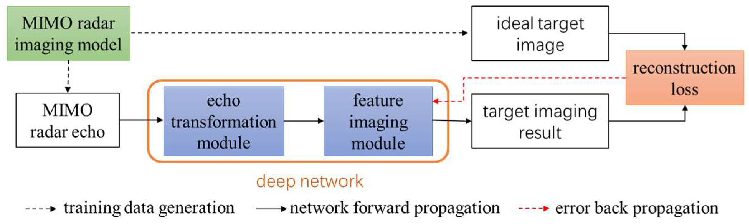
In this paper, the deep learning technology is introduced to solve the problem of non-orthogonal waveform coupling suppression, and a new non-orthogonal waveform MIMO radar imaging framework based on a deep network is proposed. The main idea is to realize the mapping from the complex echo of non-orthogonal waveform MIMO radar to the target high-resolution image through the deep network, and the key is to design a network structure suitable for non-orthogonal waveform MIMO radar imaging. The network structure based on deep expansion of the sparse reconstruction algorithm can effectively deal with complex echoes, but for non-orthogonal MIMO radar imaging, the dimension of the sparse reconstruction model is too high, and the network is difficult to realize. Convolutional neural networks and recurrent neural networks, which are widely used in the field of general deep learning, are not suitable for the data characteristics of non-orthogonal waveform MIMO radar echo, and it is difficult to learn the complex mapping from complex echo to target image. The proposed framework organically combines the MIMO radar imaging theory with the advanced deep network, provides the basis for network construction and parameter initialization through the imaging theory, and uses the advanced deep network module to improve the nonlinear fitting ability of the imaging network. The overall network structure is divided into two parts, which are called the ‘echo transformation module’ and ‘feature imaging module’. The ‘echo transformation module’ serves to extract artificial features, transform the complex echo using the traditional MIMO radar imaging theories such as matched filtering, sparse recovery, time-frequency analysis, etc., and realize the transformation from the complex echo domain of ‘implicit expression’ of information to the feature domain of ‘explicit expression’ of information. The function of the ‘feature imaging module’ is to carry out automatic feature extraction, use advanced achievements in the field of deep learning to build a network structure, and complete the nonlinear mapping from echo features to target images. The overall structure of the framework is shown in
Figure 1, which mainly includes three parts: training data generation based on the MIMO radar imaging model, deep network forward propagation, and error back-propagation based on reconstruction loss. Based on the above framework, a non-orthogonal waveform MIMO radar imaging method based on deep learning is designed in this paper. The proposed imaging method is introduced from three aspects: deep network structure, training data generation, and network training strategy.
3.1. Deep Network Structure
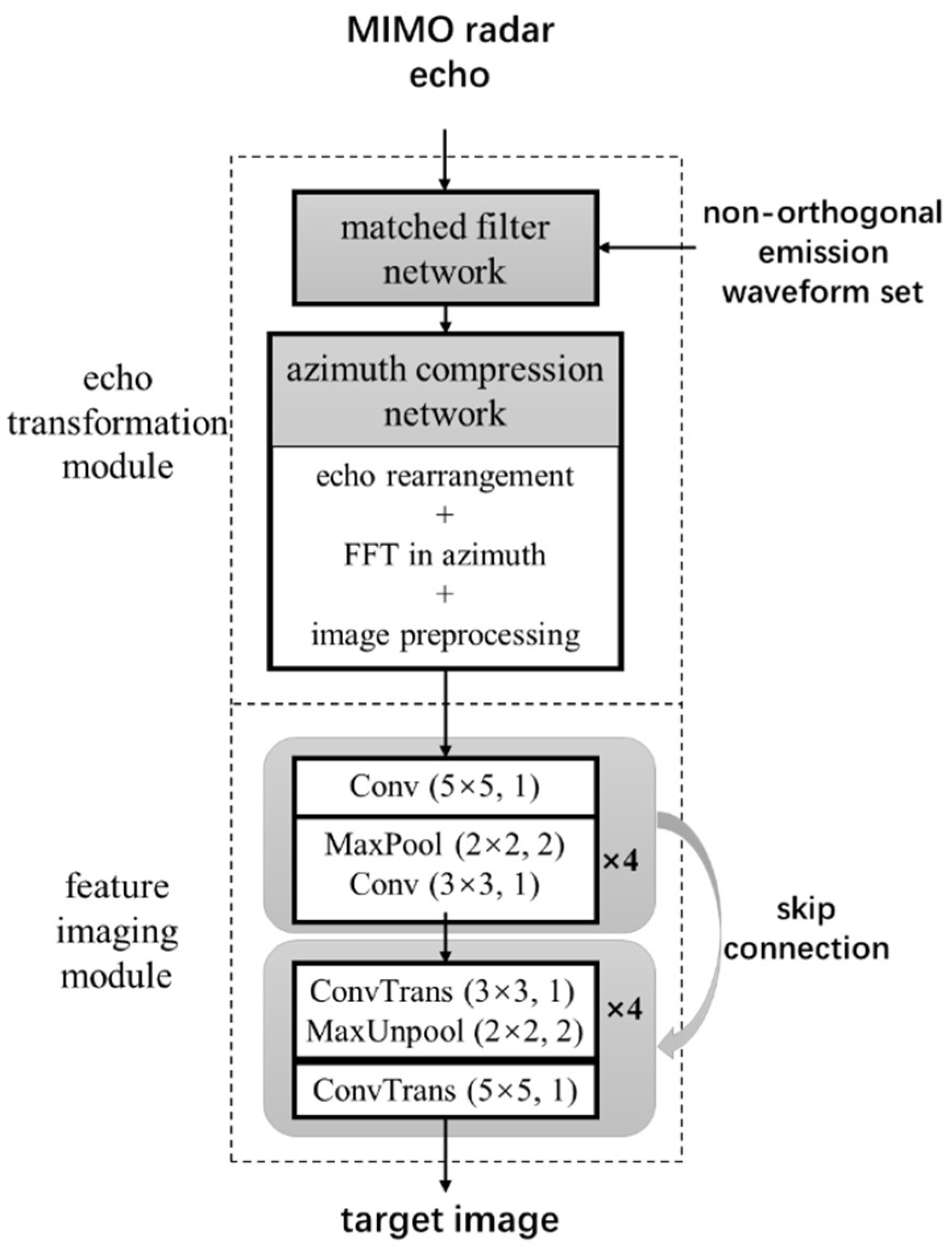
According to the specific characteristics of non-orthogonal waveform MIMO radar imaging, this paper constructs a MIMO radar learning imaging network (MIMO-LI-Net), and the network structure is shown in
Figure 2. The echo transformation module is constructed according to the range Doppler imaging algorithm, including the matched filter network and the azimuth compression network: the matched filter network completes the range dimension compression of the target echo by inputting the non-orthogonal emission waveform set. According to the configuration of the MIMO array structure, the azimuth compression network completes the two-dimensional compression of the target echo through echo rearrangement, azimuth compression, and other processes. In the specific implementation, this paper designs a uniform equivalent transceiver array and frequency domain matched filter, which can improve the efficiency of echo transformation with the help of fast Fourier transform (FFT). It should be noted that, due to the coupling interference between non-orthogonal waveforms and the possible migration though resolution cells, the above two-dimensional compression results cannot achieve the ideal imaging effect. Nevertheless, the echo transformation process still extracts effective target features from the complex echo of MIMO radar, which can provide a good initial input for the subsequent feature imaging process. The feature imaging module is constructed by a convolutional neural network, which can be divided into two parts, encoding and decoding, as shown in
Figure 2. In the figure, Conv and ConvTrans represent the convolution layer and deconvolution layer, respectively. Moreover, (3 × 3, 1) indicates that the size of the convolution kernel or deconvolution kernel is 3 × 3 and the step length is 1. After each convolution operation or deconvolution operation, a batch normalization (BN) process and a relu activation function are connected. The network consists of five convolution layers, and the number of input/output channels of each layer is 2/32, 32/64, 64/64, 64/64, and 64/128, respectively. It includes five deconvolution layers, and the number of input/output channels of each layer is 128/64, 64/64, 64/64, 64/32, and 32/1, respectively. MaxPool and MaxUnpool represent the maximum pooling layer and the maximum unpooling layer, respectively, and (2 × 2, 2) indicates that the size of the pooled or unpooled window is 2 × 2 and the window step is 2. The same location index is used for the maximum pooling layer and the maximum unpooling layer. The network includes 4 pooling layers and 4 unpooling layers, respectively. Different from general natural image processing, we send the real part and imaginary part of the echo transformation result to the CNN network as two separate channels. Compared with the input single-channel modulus data, the inputted dual-channel data contain the complete information of the transformed echo, which is conducive to image feature extraction. In addition, the feature imaging module establishes a skip connection between the coding and decoding parts of the network, which helps to retain the details of the image in the process of image reconstruction.
3.2. Training Data Generation
In order to train the above MIMO-LI-Net, sufficient training samples need to be generated. Considering that it is difficult to obtain a large number of MIMO radar measured data in practice, this paper constructs a training data set from simulation data. It can be seen from
Figure 2 that the training data include the MIMO radar target echo and the ideal target image. For the MIMO radar target echo, this paper generates the simulated MIMO radar target echo based on the parameterized attribute scattering center model and MIMO radar echo signal model in
Section 2.1. For a multi-scattering center target, its frequency domain echo at the
nth receiver of the MIMO radar can be generated by the following formula
where
is the vector composed of echoes in different frequencies,
is the vector form of the transmission waveform
in the frequency domain,
is the frequency-related vector composed of the scattering field generated by the
qth scattering center in the
mth transmitting and
nth receiving channel, and
denotes the point-to-point multiplication between two vectors. Considering the centralized MIMO imaging scene, the scattering center has stable scattering characteristics within the observation angle range of the MIMO array, and according to the attribute scattering center model [
33],
can be generated by the following formula
where
is a vector that contains all the frequency points of echoes,
is the center frequency, and
is the azimuth angle between the
qth scattering center and the equivalent transceiver of the
mth transmitter and
nth receiver.
is the sum of the wave path from the
qth scattering center to the
mth transmitter and
nth receiver.
is the parameter related to the
qth scattering center:
is the scattering coefficient;
is a parameter describing the frequency and geometric relationship of the scatterer;
represent the length and direction angle of the distributed scattering center;
describes the relationship between the local scattering center and the direction. Through the above methods, MIMO radar echoes containing both local and distributed scattering mechanism targets can be simulated.
In addition to the MIMO radar target echo, network training also requires the corresponding output target image. In this paper, the target imaging result under the condition of an ideal orthogonal waveform is used as the target image. The specific method is as follows: using the equivalent transceiver array echo to replace the MIMO array echo shown in Formula (9), at this time, the echoes of different transmitted waveforms are not aliased and there is no coupling interference; the back-projection algorithm is used to image the echo of the equivalent transceiver array. Even if there is migration though resolution cells, the algorithm can still obtain the focused image; the sidelobe is suppressed by two-dimensional windowing, and the image resolution is improved by doubling the array length and doubling the signal bandwidth.
3.3. Network Training Strategy
Through effective network learning, the imaging network can be driven to automatically learn the mapping from the non-orthogonal waveform echo to the ideal target image from a large number of training samples. In MIMO-LI-Net, the echo transformation module does not contain learnable parameters, so the network only needs to learn the CNN parameters in the feature imaging module. In this paper, the mean square error between the reconstructed target image and the ideal target image is used as the loss function, and the back-propagation algorithm is used to train the network.
4. Experimental Results
This part first trains the proposed imaging network by generating simulation data, and then verifies the effect of the proposed imaging method by using two sets of test data. The simulation experiment adopts a MIMO linear array with 4 transmitters and 20 receivers. The interval between transmitting and receiving array elements is 3 m and 60 m, respectively, the radar center frequency is 10 GHz, and the transmitting waveform is 4 polyphase coded signals with 450 symbols. The signal bandwidth is 300 MHz. The time duration is 1.5 μs. The range scope is set as 50 m, which corresponds to the time duration 0.333 μs. The sampling interval in frequency is 0.545 MHz and the frequency scope is set as 768 MHz, which corresponds to a time sampling interval of 1.3 ns. Therefore, the number of frequencies is 768 ÷ 0.545 ≈ 1410. The autocorrelation sidelobe of the four signals is low, but the cross-correlation sidelobe is high. This means that the waveform does not meet the ideal orthogonality. We set the target 5 km away from the center of the array, and the corresponding range and azimuth theoretical imaging resolutions are 0.5 m and 0.625 m, respectively. The training samples are generated by the method in
Section 3.2. The number of scatterers of each target is uniformly and randomly generated in the range of 0~500, and all of them are in the range of 50 m × 50 m. The scattering coefficient of the scatterer is generated by the standard complex Gaussian distribution. Each scatterer is set as the distributed scattering center or local scattering center with equal probability, and the length of the distributed scattering center is a uniform random number in the range of 0~2 m. We set the size of the ideal target image to 256 × 256. A total of 40,000 training sample pairs of MIMO radar echo and target image are generated to form a training data set for training the MIMO-LI-Net shown in
Figure 2. The training platform is an Intel Core i9-9900 CPU and NVIDIA geforce RTX 2080 Ti GPU, which has the memory size of 11 GHz. Under the Pytorch framework, the Adam optimizer is used for training, and the learning rate is set to 0.0001. There are 40,000 training samples. The batch size is set as 32, which occupies 4.8 GHz GPU memory. One training epoch takes around 13 min. In the training, we set the number of training epochs as 100. Thus, the total training time is around 21.67 h. For the imaging network after training, in the following, we will verify the trained imaging network by building test data.
4.1. Experiment of Point Target Simulation Data
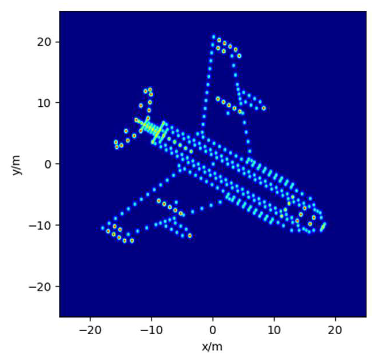
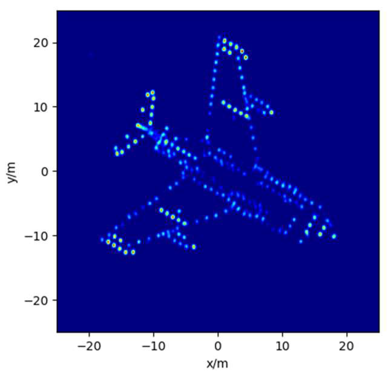
Firstly, an aircraft target model composed of ideal scattering points is considered. The imaging parameters are consistent with the training data. We use the method in
Section 3.2 to generate the MIMO radar echo and the ideal target image, which is shown in
Figure 3. Four existing MIMO radar imaging methods are selected for comparison. (1) The matched filtering method—range compression is carried out based on Equation (4), and FFT is carried out to realize azimuth compression. (2) The 1D-SR method—a one-dimensional sparse recovery (1D-SR) model is constructed by using the method proposed in [
16] to directly solve the two-dimensional image of the target. It should be noted that, due to the high dimension of the one-dimensional vector model (in this experiment, the dimension of the perception matrix is up to 11,000 × 8000), the efficiency of the sparse solving algorithm in [
16], which involves matrix inversion, is too low. Therefore, this paper uses the more efficient orthogonal matching pursuit (OMP) algorithm to solve the sparse model, and the sparsity for OMP is set to 400. (3) The MB-SL0 method—the MB-SL0 algorithm proposed in [
14] is used for the range compression, and then the azimuth compression is realized through FFT. (4) The CNN method—we train a CNN network for MIMO radar imaging. The network input is the imaging result of the matched filtering method. The network structure is similar to MIMO-LI-Net, but does not include skip connections between network layers. The network training method is consistent with the training method of the proposed imaging network.
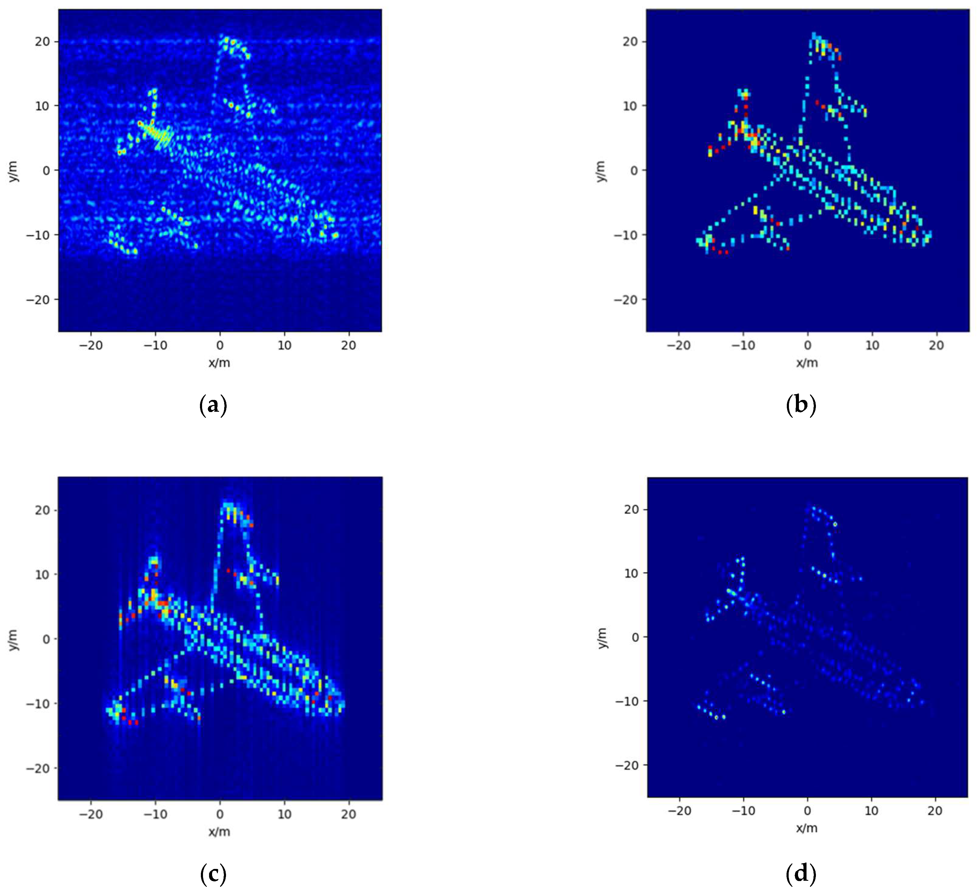
The imaging results of the four comparison methods are shown in
Figure 4. As can be seen from
Figure 4a, due to the non-ideal orthogonality of the transmitted waveform, there is serious mutual coupling noise in the imaging result of the matched filtering method.
Figure 4b shows the imaging results of the 1D-SR method. It can be seen that the 1D-SR method can well suppress the mutual coupling noise, but, due to the basis mismatch of the sparse reconstruction model, there is a certain position shift in the scattering points in the sparse reconstructed image compared with the ideal image. Moreover, the sparsity parameter of the OMP algorithm needs to be set manually. When the sparsity is small, the scattering points will be lost, and when the sparsity is large, the computational complexity will increase sharply. As can be seen from
Figure 4c, the MB-SL0 method can effectively suppress the range coupling interference caused by the non-orthogonality of the waveform, but the sidelobe is high in the azimuth direction. Moreover, due to the decoupling processing of distance and azimuth, when the scattering points far away in the azimuth undergo migration over distance units, the imaging results will be defocused.
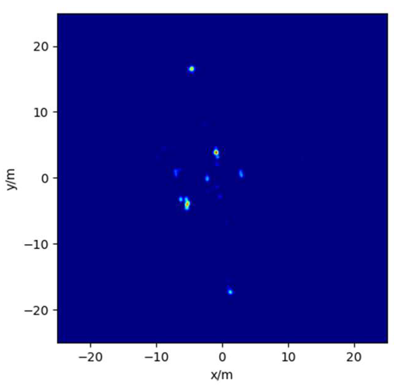
Figure 4d shows the imaging results of the CNN method. It can be seen that the CNN method can better suppress the image coupling interference caused by non-orthogonal waveforms. However, due to the lack of targeted design of the network structure, the network has a poor effect on the recovery of weak scattering points in the image. The imaging results of MIMO-LI-Net, trained in this paper, are shown in
Figure 5. From the figure, we can see that most scattering points on the target have been well recovered, and the coupling interference between non-orthogonal waveforms has been effectively suppressed.
In order to quantitatively analyze the above imaging results, normalized mean square error (NMSE) and target background ratio (TBR) [
32] are used as evaluation indicators. In TBR, the threshold is set to 0.0001. The index calculation results of each method are shown in
Table 2. It can be seen that the imaging index of the matched filtering method is the worst, and the method in this paper has achieved the best results in NMSE and TBR. At the same time, in order to compare the calculation efficiency of various methods,
Table 2 also shows the running time of different methods under CPU. It can be seen that the operation efficiency of the matched filtering method is the highest. The running time of the 1D-SR method is the longest, reaching nearly 100 s. With the increase in the dimension of the imaging model and the sparsity of the OMP algorithm, the demand for storage space and computing resources of the algorithm will increase sharply. The running times of the MB-SL0 method, CNN method, and the proposed method are lower, all of which are in the order of 0.1 s. Compared with the MB-SL0 method, the running efficiency of the CNN method and the proposed method is less affected by the increase in imaging model dimension.
4.2. Experiment on Electromagnetic Calculation Data
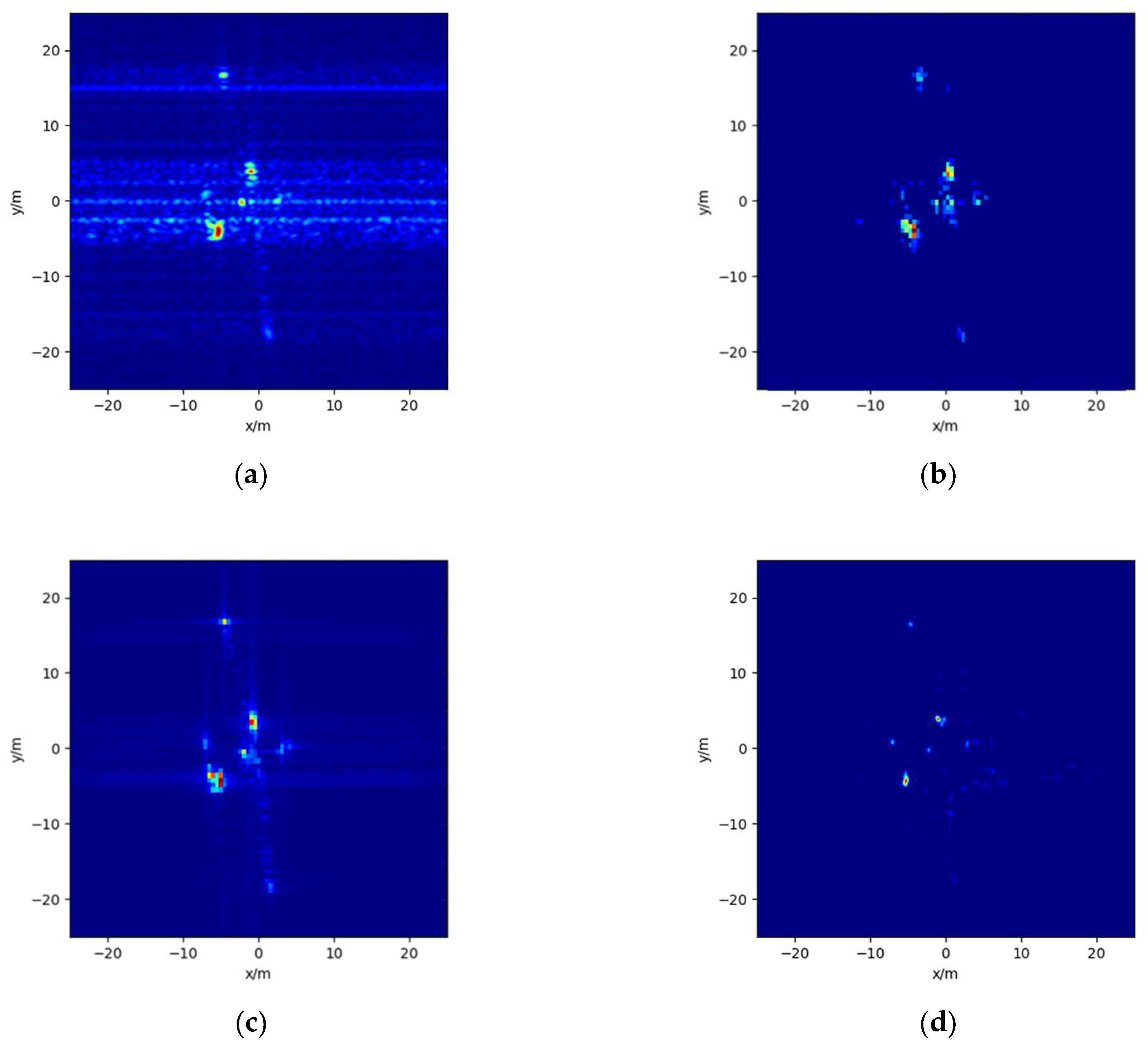
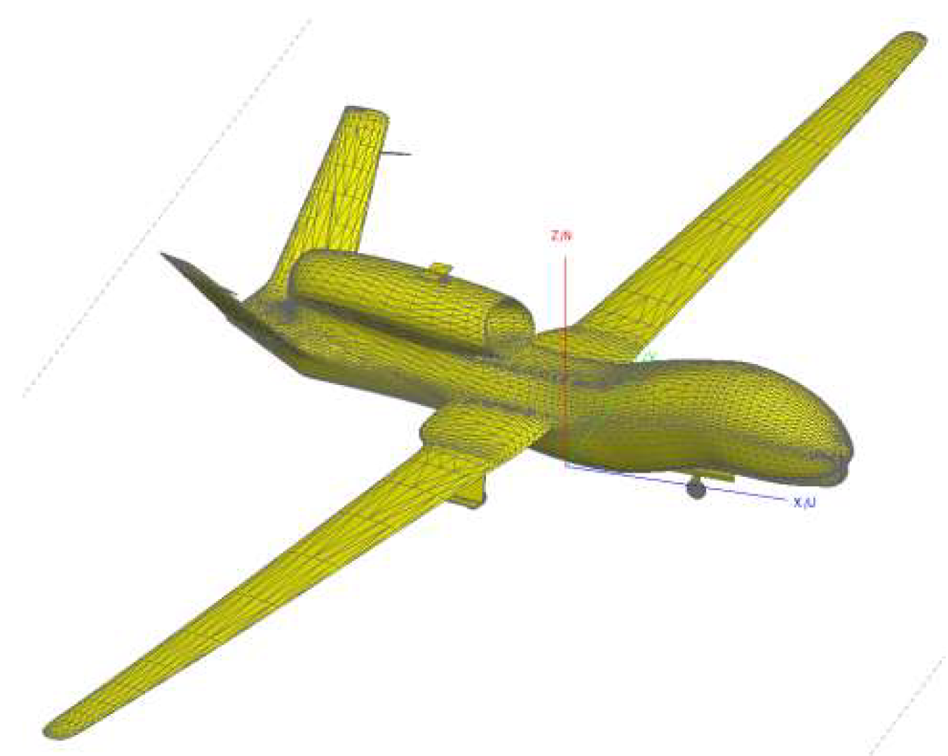
In this part, the performance of the proposed imaging method is further tested by using the electromagnetic calculation data. The CAD model of the target is shown in
Figure 6. Physical optics and the method of moments are used as electromagnetic scattering calculation methods to generate the target scattering field, and the MIMO radar echo of the target can be generated by using Equation (9). The imaging results of the target for each comparison method and the proposed imaging method are shown in
Figure 7 and
Figure 8, respectively. It can be seen that for non-ideal point scattering model targets, the proposed method can also effectively suppress the mutual coupling noise of non-orthogonal waveforms, while retaining the main scattering center of the target. Compared with the results of other comparison methods, the results of the proposed method have lower sidelobes and fewer false points.
5. Discussions
In this manuscript, we mainly focus on the specific error in MIMO array radar, i.e., the waveform coupling. Besides the specific error, there are some general errors that are common to all the array radars, including the channel gain and phase error, array element position error, carrier error, imaging model error, noise, etc. Since both array element position error and carrier error will eventually lead to channel phase error, they can be dealt with as the channel phase error. For MIMO array imaging, the channel phase errors usually have a great impact. A large phase error may lead to imaging failure. The noise usually has a slight influence, and will reduce the signal-to-noise ratio of the image to some extent. The mutual coupling among waveforms will enhance the range sidelobes and degrade the image quality eventually. The imaging model error may result in a deformed image, reduce the signal-to-noise ratio, and so on. In this work, we propose a new method to deal with the error of waveform coupling. For the random general errors, some error correction methods will be necessary. There have been many studies focused on correcting the various errors, such as the method in [
2]. One possible approach to combine the existing error correction methods with the proposed imaging network is embedding the correction methods into the ‘echo transformation module’ in
Figure 2. In this way, the correction methods can be directly applied with little change. Moreover, another potential approach is described in [
27,
28,
29], by combining the step of error correction with the network in the ‘feature imaging module’, in which the network structure needs to be changed significantly.
In this work, we train the proposed network via simulated data. There may be some degradations for various real scenarios in practice. In order to improve its performance on real scenarios, one strategy is to build a more accurate simulated system model and produce more accurate simulated training data. In addition, it is also important, for the deep-learning based method, to collect measured data as much as possible. However, often, it is very difficult to obtain enough measured data in practice. Transfer learning, as one of the most important techniques in deep learning, can transfer knowledge from the simulated data to the real data, and then good performance on the real test data can be obtained by fine-tuning the pre-trained network (which is trained via a large number of simulated data) via only a small number of real training data. Therefore, it is possible to expand the proposed network trained via simulated data to different scenarios in real microwave imaging.
6. Conclusions
In this paper, deep learning technology is introduced into the field of MIMO radar imaging, and a new MIMO radar imaging method suitable for non-orthogonal waveforms is proposed. This method only needs to transmit the common non-orthogonal signal waveforms, and the echo is post-processed through the training deep network. It can effectively suppress the coupling interference of different waveforms and efficiently obtain a high-resolution image of the target. The experimental results verify that, by training the proposed imaging network on the simulation data set, a good imaging effect can be obtained on the point scattering target data and electromagnetic calculation data. In the follow-up, we will continue to study the organic combination method of existing imaging theory and deep networks, build a more advanced echo transformation module, improve the quality of target echo feature extraction, and further improve the recovery effect of the imaging network on weak scattering points. Moreover, near-field microwave-based tomography, which is closely related to radar imaging, has wide application prospects, such as medical diagnosis or industrial testing. Thus, it would also be valuable to expand our proposal to the field of near-field microwave-based tomography.


