
Optimal Design Parameters for Hybrid DC Circuit Breakers Using a Multi-Objective Genetic Algorithm


Abstract
:1. Introduction
- A MOGA-based optimization model that can optimally design the parameters of HCB topologies, which aims to achieve a trade-off between reducing the peak fault current, interruption time, and recovery time.
- A MOGA that allows the proposed model to handle both discrete and continuous variables, and therefore solve complex optimal design problems.
- An in-depth comparison study between the initial and optimal parameters of HCB topologies, the results of which showed that the proposed method provided the optimal parameters for the HCB topologies, and therefore significantly reduced the peak value of the fault current, the interruption time, and the recovery time.
2. HCB Topology and Problem Statement
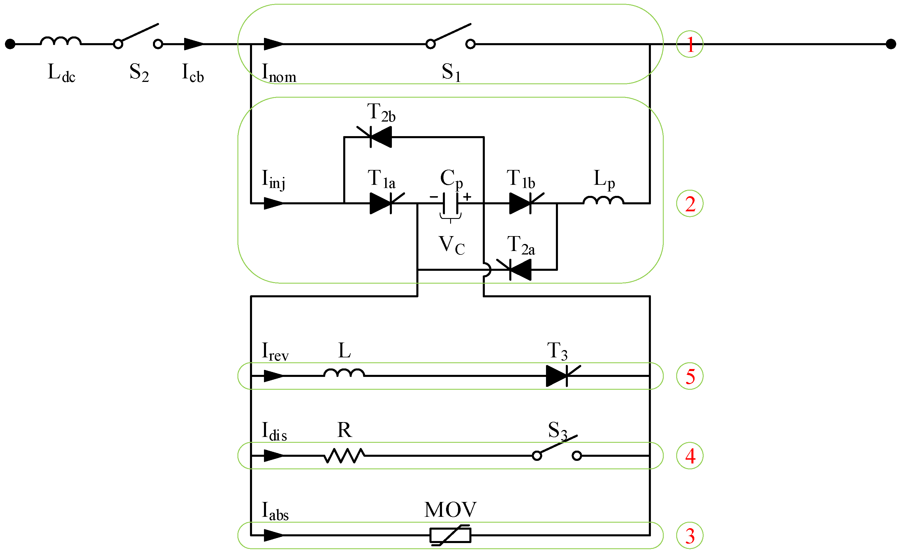
2.1. HCB Topology
2.1.1. Configuration of the HCB
2.1.2. Working Principle of the HCB
2.2. Problem Statement
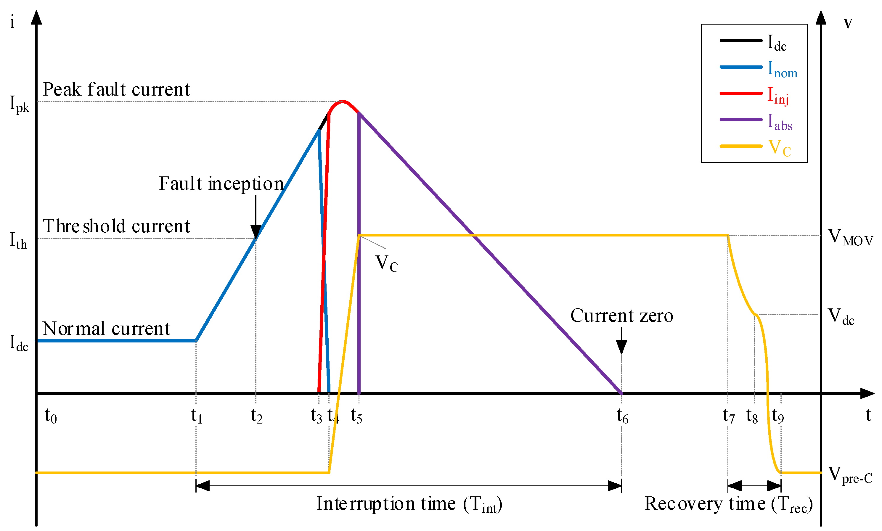
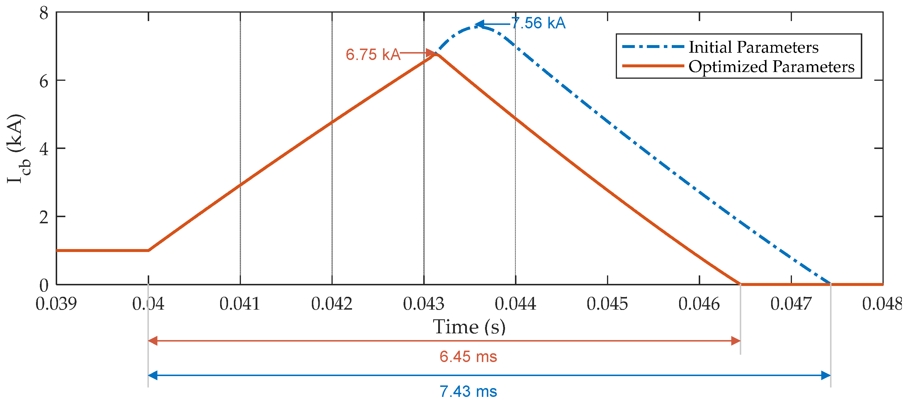
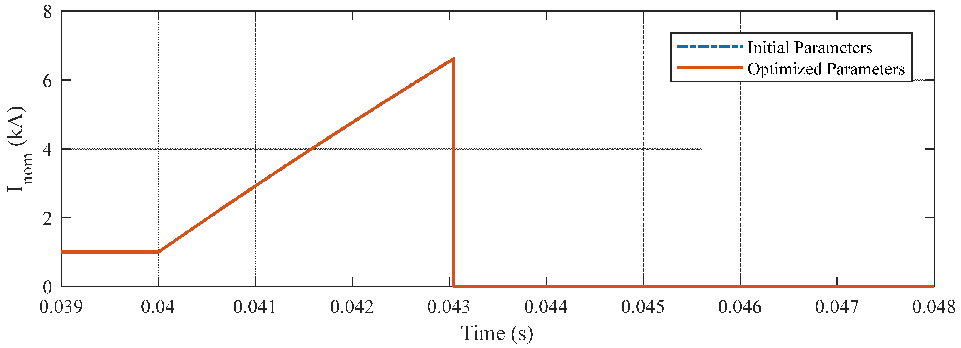
- Peak fault current () is the maximum value of the fault current flowing through the HCB during fault current interruption. The fault current is computed by tracking the fault current, as given in (1).
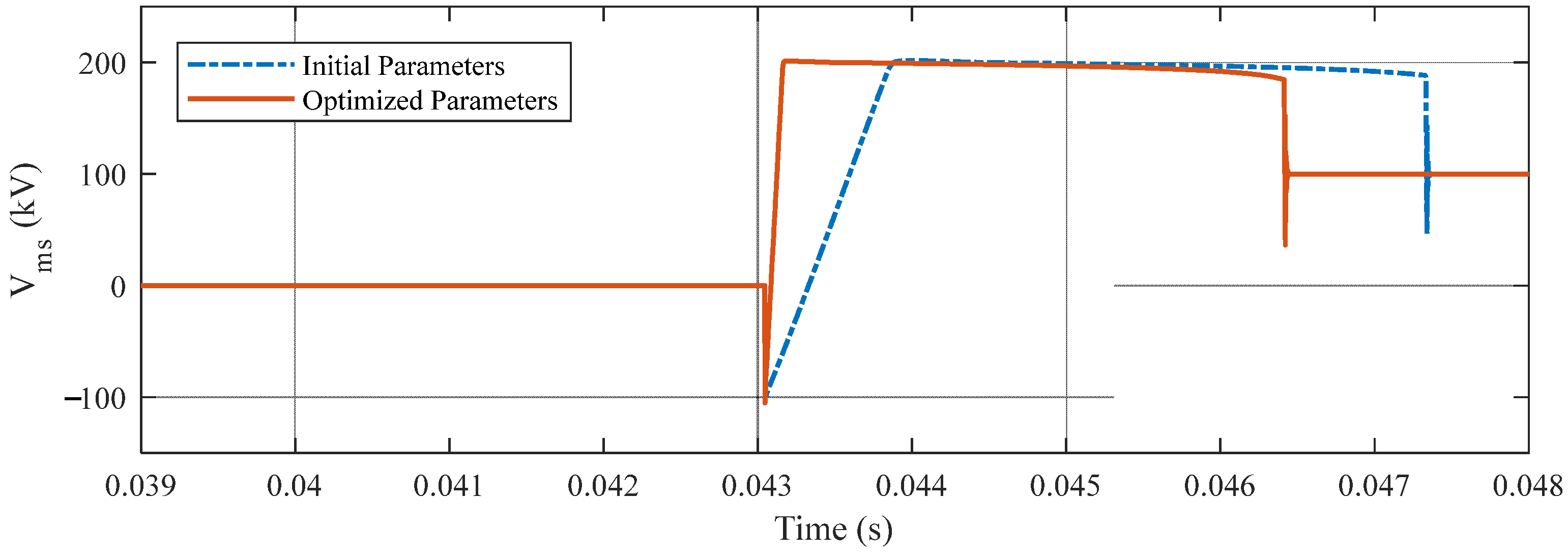
- Interruption time () is the total time to clear the short-circuit fault from the grid. This time period is determined from fault inception () until fault clearing () and can be given as (2).
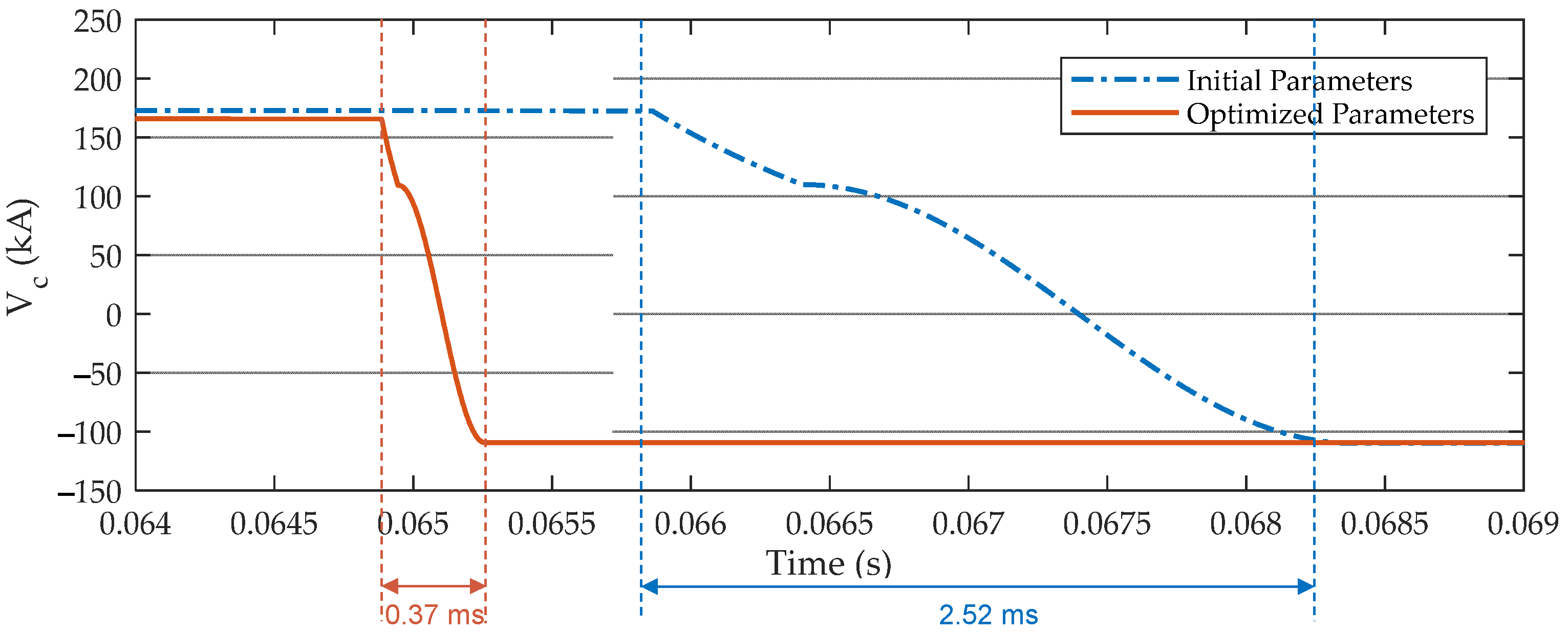
- Recovery time () is the total time to recover the capacitor voltage to normal condition. This period starts from the discharge mode () until the reverse mode ends () and can be computed by (3).
3. Parameters Optimization Using Multi-Objective Genetic Algorithm
3.1. Multi-Objective Formulation
3.2. Operation Constraints
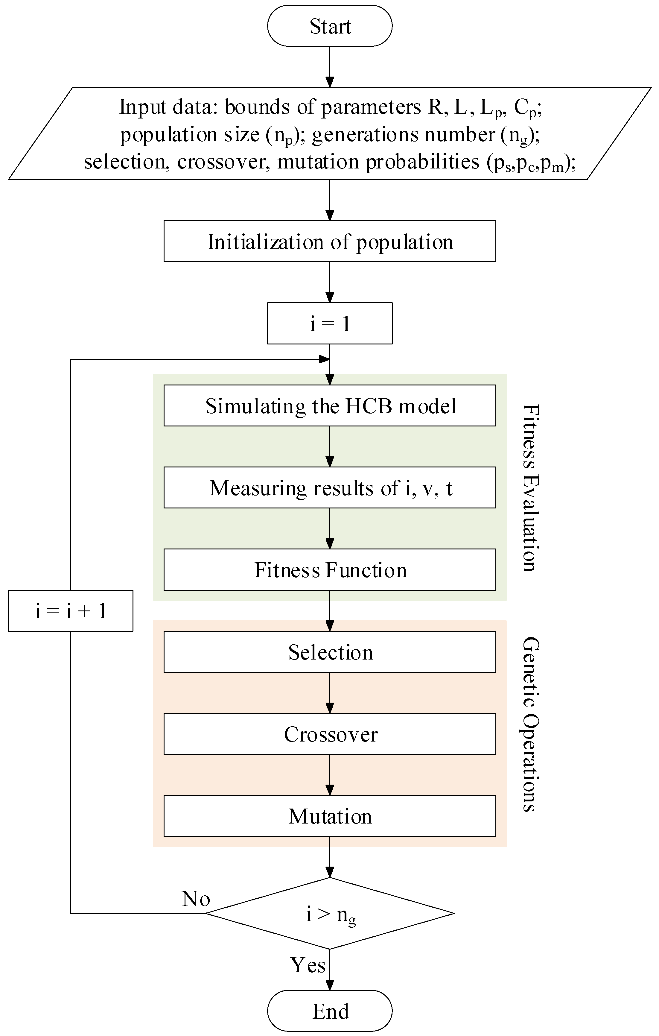
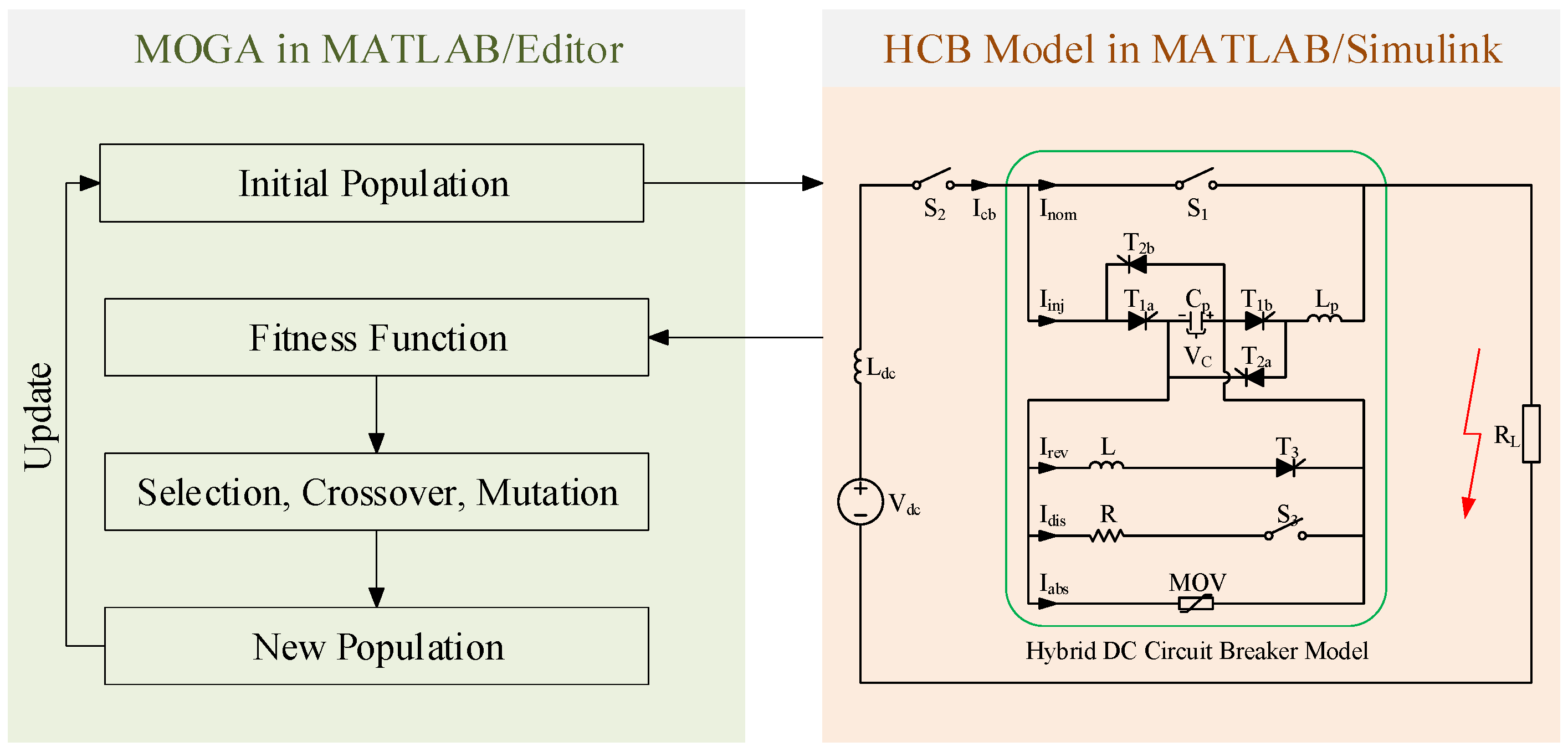
3.3. Process of the Proposed MOGA
4. Simulation Results
4.1. Test System
4.2. Results and Analysis
4.2.1. Results of Optimizing Parameters for the HCB by Using the MOGA
4.2.2. Comparison of Using the Initial and Optimized Parameters of the HCB
5. Conclusions
Author Contributions
Funding
Institutional Review Board Statement
Informed Consent Statement
Data Availability Statement
Conflicts of Interest
References
- Flourentzou, N.; Agelidis, V.G.; Demetriades, G.D. VSC-based HVDC power transmission grids: An overview. IEEE Trans. Power Electron. 2009, 24, 592–602. [Google Scholar] [CrossRef]
- Deng, F.; Chen, Z. Operation and control of a dc-grid offshore wind farm under dc transmission grid faults. IEEE Trans. Power Del. 2013, 28, 1356–1363. [Google Scholar] [CrossRef]
- Akhmatov, V.; Callavik, M.; Franck, C.M.; Rye, S.E.; Ahndorf, T.; Bucher, M.K.; Muller, H.; Schettler, F.; Wiget, R. Technical guidelines and prestandardization work for first HVDC grids. IEEE Trans. Power Del. 2014, 29, 327–335. [Google Scholar] [CrossRef]
- Bucher, M.K.; Franck, C.M. Contribution of fault current sources in multiterminal HVDC cable networks. IEEE Trans. Power Del. 2013, 28, 1796–1803. [Google Scholar] [CrossRef]
- Franck, C.M. HVDC circuit breakers: A review identifying future research needs. IEEE Trans. Power Del. 2011, 26, 998–1007. [Google Scholar] [CrossRef]
- Chen, Z. Analysis and experiments for IGBT, IEGT, and IGCT in hybrid DC circuit breaker. IEEE Trans. Ind. Electron. 2018, 65, 2883–2892. [Google Scholar] [CrossRef]
- Benfatto, I.; Maschio, A.; Manganaro, S. DC breaking tests up to 55 kA in a single vacuum interrupter. IEEE Trans. Power Del. 1988, 3, 1732–1738. [Google Scholar] [CrossRef]
- Eriksson, T.; Backman, M.; Halen, S. A low loss mechanical HVDC breaker for HVDC grid applications. In Proceedings of the CIGRE Session, Paris, France, 24 August 2014. Paper B4-303. [Google Scholar]
- Shi, Z.Q.; Zhang, Y.K.; Jia, S.L.; Song, X.C.; Wang, L.J.; Chen, M. Design and numerical investigation of a HVDC vacuum switch based on artificial current zero. IEEE Trans. Dielectr. Elect. Insul. 2015, 22, 135–141. [Google Scholar] [CrossRef]
- Kempkes, M.; Roth, I.; Gaudreau, M. Solid-state circuit breakers for medium voltage dc power. In Proceedings of the 2011 IEEE Electric Ship Technologies Symposium, Alexandria, VA, USA, 10–13 April 2011; pp. 254–257. [Google Scholar]
- Jang, H.-J.; Lee, W.-Y.; Park, S.; Chong, J.-K. A configuration concept of solid-state switch for 2kV class DC circuit breaker. In Proceedings of the 2015 3rd International Conference on Electric Power Equipment—Switching Technology (ICEPE-ST), Busan, Korea, 25–28 October 2015; pp. 435–437. [Google Scholar]
- Meyer, C.; Kowal, M.; De Doncker, R.W. Circuit breaker concepts for future high-power dc-applications. In Proceedings of the Fourtieth IAS Annual Meeting. Conference Record of the 2005 Industry Applications Conference, Hong Kong, China, 2–6 October 2005; Volume 2, pp. 860–866. [Google Scholar]
- Sano, K.; Takasaki, M. A surgeless solid-state DC circuit breaker for voltage-source-converter-based HVDC systems. IEEE Trans. Ind. Appl. 2014, 50, 2690–2699. [Google Scholar] [CrossRef]
- Van Gelder, P.; Ferreira, J.A. Zero volt switching hybrid DC circuit breakers. In Proceedings of the Conference Record of the 2000 IEEE Industry Applications Conference. Thirty-Fifth IAS Annual Meeting and World Conference on Industrial Applications of Electrical Energy (Cat. No.00CH37129), Rome, Italy, 8–12 October 2000; Volume 5, pp. 2923–2927. [Google Scholar]
- Bösche, D.; Wilkening, E.-D.; Köpf, H.; Kurrat, M. Breaking performance investigation of hybrid DC circuit breakers: An Experimental Approach. In Proceedings of the 2015 IEEE 61st Holm Conference on Electrical Contacts (Holm), San Diego, CA, USA, 11–14 October 2015; pp. 117–123. [Google Scholar]
- Bösche, D.; Wilkening, E.-D.; Köpf, H.; Kurrat, M. Hybrid DC circuit breaker feasibility study. IEEE Trans. Compon. Packag. Manuf. Technol. 2017, 7, 354–362. [Google Scholar] [CrossRef]
- Häfner, J.; Jacobson, B. Proactive Hybrid HVDC Breakers—A key innovation for reliable HVDC grids. In Proceedings of the CIGRE Bologna Symposium—The Electric Power System of the Future: Integrating Supergrids and Microgrids, Bologna, Italy, 13–15 September 2011; pp. 1–9. [Google Scholar]
- Davidson, C.C.; Whitehouse, R.S.; Barker, C.D.; Dupraz, J.-P.; Grieshaber, W. A new ultra-fast HVDC circuit breaker for meshed dc networks. In Proceedings of the 11th IET International Conference on AC and DC Power Transmission, Birmingham, UK, 10–12 February 2015; pp. 1–7. [Google Scholar]
- Wu, Y.; Hu, Y.; Wu, Y.; Rong, M.; Yi, Q. Investigation of an active current injection DC circuit breaker based on a magnetic induction current commutation module. IEEE Trans. Power Deliv. 2018, 33, 1809–1817. [Google Scholar] [CrossRef]
- Sander, R.; Suriyah, M.; Leibfried, T. Characterization of a countercurrent injection-based HVDC circuit breaker. IEEE Trans. Power Electron. 2018, 33, 2948–2956. [Google Scholar] [CrossRef]
- Nguyen, V.-V.; Son, H.-I.; Nguyen, T.-T.; Kim, H.-M.; Kim, C.-K. A novel topology of hybrid HVDC circuit breaker for VSC-HVDC application. Energies 2017, 10, 1675. [Google Scholar] [CrossRef]
- Liu, L.; Liu, S.; Popov, M. Optimized algorithm of active injection circuit to calibrate DC circuit breaker. Int. J. Electr. Power Energy Grid 2018, 103, 369–376. [Google Scholar] [CrossRef]
- Liu, Y.; Zhan, X.; Li, R. Optimization design and application of converter parameters of DC vacuum circuit breaker. In Proceedings of the 2017 20th International Conference on Electrical Machines and Grids (ICEMS), Sydney, Australia, 11–14 August 2017; IEEE: Piscataway, NJ, USA. [Google Scholar]
- Liu, X.; Yu, D.; Zou, J.; Liao, M. The Multi-objective optimization design of commutation circuit in DC vacuum circuit breaker. In Proceedings of the 2014 International Symposium on Discharges and Electrical Insulation in Vacuum (ISDEIV), Mumbai, India, 28 September–3 October 2014; IEEE: Piscataway, NJ, USA. [Google Scholar]
- Wen, W. Research on a current commutation drive circuit for hybrid DC circuit breaker and its optimisation design. IET Gener. Transmiss. Distrib. 2016, 10, 3119–3126. [Google Scholar] [CrossRef]
- Shabir, S.; Singla, R. A comparative study of genetic algorithm and the particle swarm optimization. Int. J. Electr. Eng. 2016, 9, 215–223. [Google Scholar]
- Lin, C.D.; Anderson-Cook, C.M.; Hamada, M.S.; Moore, L.M.; Sitter, R.R. Using Genetic Algorithms to Design Experiments: A Review. Qual. Reliab. Engng. Int. 2014, 31, 155–167. [Google Scholar] [CrossRef]
- Conseil International des Grands Réseaux Électriques (Ed.) Technical Requirements and Specifications of State-of-the-Art HVDC Switching Equipment; CIGRÉ: Paris, France, 2017; ISBN 978-2-85873-386-6. [Google Scholar]
- Murata, T.; Ishibuchi, H. MOGA: Multi-objective genetic algorithms. In Proceedings of the 1995 IEEE International Conference on Evolutionary Computation, Perth, WA, Australia, 29 November–1 December 1995; pp. 289–294. [Google Scholar]
- Liu, S.; Popov, M. Development of HVDC System-Level Mechanical Circuit Breaker Model. Int. J. Electr. Power Energy Syst. 2018, 103, 159–167. [Google Scholar] [CrossRef]
- Greenwood, A.; Lee, T. Theory and Application of the Commutation Principle for HVDC Circuit Breakers. IEEE Trans. Power Appar. Syst. 1972, PAS-91, 1570–1574. [Google Scholar] [CrossRef]
- Kontos, E.; Pinto, R.T.; Rodrigues, S.; Bauer, P. Impact of HVDC transmission system topology on multiterminal DC network faults. IEEE Trans. Power Deliv. 2015, 30, 844–852. [Google Scholar] [CrossRef]
- Liu, G.; Xu, F.; Xu, Z.; Zhang, Z.; Tang, G. Assembly HVDC breaker for HVDC grids with modular multilevel converters. IEEE Trans. Power Electron. 2017, 32, 931–941. [Google Scholar] [CrossRef]


| States | Definition and Operation | Time |
|---|---|---|
| Normal operation | Breaker operates in normal conduction condition:
| |
| Fault inception | Fault current arrives at the circuit breaker location:
| |
| Relay time | Time for fault detection:
| |
| Fault interruption | After a delay time of switch :
| |
| Residual switch open | Residual current circuit breaker () opens:
| |
| Discharging operation | Capacitor is discharged to the system voltage. | |
| Reversing operation | Polarity of the capacitor is changed and opposite to the system voltage. |
| Parameter (Unit) | Range of Values |
|---|---|
| 40–80 | |
| 2–40 | |
| 0.3–6.67 | |
| 1.8–24 |
| Component | Symbol | Value |
|---|---|---|
| Rated DC voltage | 100 kV | |
| Rated DC current | 1 kA | |
| System inductance | 50 mH | |
| Capacitor precharge voltage | −100 kV | |
| Load resistance | 100 Ω | |
| Threshold current | 3 kA | |
| Protection voltage level | 200 kV |
| Parameters | Type | Value |
|---|---|---|
| Population size () | Randomly normalized | 30 |
| Selection probability () | Roulette wheel | 2/30 |
| Crossover probability () | Single point | 0.8 |
| Mutation probability () | Uniform random | 0.2 |
| Stopping criteria () | Number of generations | 500 |
| Component (Unit) | Initial Parameters | Optimized Parameters | Reducing (%) |
|---|---|---|---|
| (kA) | 7.56 | 6.75 | 5.66 |
| (ms) | 7.43 | 6.45 | 7.06 |
| (ms) | 2.52 | 0.37 | 74.39 |
Publisher’s Note: MDPI stays neutral with regard to jurisdictional claims in published maps and institutional affiliations. |
© 2022 by the authors. Licensee MDPI, Basel, Switzerland. This article is an open access article distributed under the terms and conditions of the Creative Commons Attribution (CC BY) license (https://creativecommons.org/licenses/by/4.0/).
Share and Cite
Nguyen, V.-V.; Nguyen, N.-T.; Nguyen, Q.-T.; Bui, V.-H.; Su, W. Optimal Design Parameters for Hybrid DC Circuit Breakers Using a Multi-Objective Genetic Algorithm. Algorithms 2022, 15, 298. https://doi.org/10.3390/a15090298
Nguyen V-V, Nguyen N-T, Nguyen Q-T, Bui V-H, Su W. Optimal Design Parameters for Hybrid DC Circuit Breakers Using a Multi-Objective Genetic Algorithm. Algorithms. 2022; 15(9):298. https://doi.org/10.3390/a15090298
Chicago/Turabian StyleNguyen, Van-Vinh, Nhat-Tung Nguyen, Quang-Thuan Nguyen, Van-Hai Bui, and Wencong Su. 2022. "Optimal Design Parameters for Hybrid DC Circuit Breakers Using a Multi-Objective Genetic Algorithm" Algorithms 15, no. 9: 298. https://doi.org/10.3390/a15090298
APA StyleNguyen, V.-V., Nguyen, N.-T., Nguyen, Q.-T., Bui, V.-H., & Su, W. (2022). Optimal Design Parameters for Hybrid DC Circuit Breakers Using a Multi-Objective Genetic Algorithm. Algorithms, 15(9), 298. https://doi.org/10.3390/a15090298