1. Introduction
The generation of electric power on board a spacecraft is fundamental to guarantee the survival of the space system. Whenever a satellite is powered by exploiting the electricity generated from the solar arrays, the capability to orient them to the Sun is a vital requirement for the system design. Solar array orientation can be achieved with a solar array drive assembly (SADA), with a proper rotation of the spacecraft, or with a combination of these two. However, the SADA cannot fully orient the solar panel in three-dimensional space, and many spacecraft are even not equipped with these orientation devices. Thus, the solar arrays pointing to the Sun are commonly demanded to the attitude determination and control subsystem (ADCS) of the spacecraft, which rotates the satellite body in a way to generate the proper electric power with the available solar cells. Given the relevance of this ability for the maintenance of the spacecraft health status, the ADCS should be capable to orient the solar panels to the Sun even after multiple failures have occurred on-board. Hence, the most dramatic safe mode-or survival mode-should guarantee a minimum power generation to support the basic functions of the space system. For these reasons, the availability of a robust and fault-tolerant ADCS, with an emergency Sun pointing mode, is crucial for the resilience of the entire system with respect to unexpected circumstances.
The paper presents an attitude determination and control subsystem design for solar arrays pointing to the Sun, with a minimal set of sensors and actuators. The sensors are limited to the solar arrays and to the angular rates sensing devices, and the actuators are required to provide a torque only along two orthogonal axes. The proposed ADCS exploits the current/voltage sensing capacity of the electrical power subsystem to measure the Sun angle with respect to the arrays normal. In fact, this research work considers a spacecraft with the solar arrays orthogonal to one direction in a body reference frame. As a consequence, the complete Sun direction unit vector cannot be estimated from the electric measurements. This assumption is motivated by the fact that common spacecraft have the Solar arrays deployed along a single axis of the spacecraft, with all the solar cells lying in a single plane. Even if this is not always the case, and additional secondary solar cells may be pointed in other directions, the larger primary solar panels area commonly has a unique normal direction. The determination and control algorithms compute the angle of the Sun with respect to the solar arrays normal and command the actuators to rotate the spacecraft in a way that this angle is minimized, having the Sun perpendicular to the solar arrays. The rotation of the spacecraft around the direction orthogonal to the solar panels is not controlled, being not relevant for electric power generation. The control algorithm is based on sequenced pulsed rotation commands modulating a proportional-derivative (PD) control scheme. The angular rate measurements are needed to have a proper derivative control implementation. The proportional control direction is unknown from the solar arrays data, and the algorithm is capable to find the necessary rotation until the correct Sun pointing is achieved. If the Sun is behind the solar arrays, a constant rotation is commanded until the Sun is in the visibility of the solar cells, producing the electric power that is needed to drive the proposed ADCS. The constant rotation is not commanded if the spacecraft is in eclipse, when the spacecraft is controlled to maintain null angular velocity. The methods to detect the eclipse condition are briefly described in the paper as well. The outcome of the research work is the sequenced and pulsed modulation algorithm, superimposed to a classic PD control, to implement an ADCS capable to orient the spacecraft solar arrays to the Sun by exploiting an incomplete Sun direction estimation. The only data available from the determination section is the angle of the Sun with respect to the solar arrays normal, and the control direction is guessed by a properly sequenced and pulsed control modulation algorithm. The purpose of the research is to have a very basic ADCS, capable to work with a minimal hardware set, in a way to sustain the spacecraft power generation even in the worst-case survival mode scenario. This is motivated by the need to increase the spacecraft reliability, especially when many redundant components cannot be installed on-board, such as in small satellite platforms [
1,
2].
The problem of spacecraft ADCS is technologically mature, and existing literature contains many references and dedicated handbooks [
3,
4]. Classical attitude determination methods are based on vector measurements of known physical quantities and celestial objects locations [
5]. At least two vector measurements are needed to determine the complete three-dimensional attitude state [
6,
7], with different estimation methods [
8]. This is well established in-flight applications [
9,
10], even with very basic sensor components [
11]. Analogously, attitude control has an endorsed heritage since the 70’s of the last century [
12]. Various control methods have been proposed [
13,
14,
15], and applications to small spacecraft have become very common [
16]. Moreover, diverse actuation methods have been deeply investigated [
17,
18,
19,
20]. However, according to previous literature, a spacecraft with only Sun angle and angular rates measurements would be not capable to align its solar arrays to the Sun. Existing works already exploited solar cells as sources of Sun direction information [
21,
22], and even common industrial applications retrieve the Sun angles in body reference frame from the electric power data to have a coarse Sun direction estimation. This is commonly accomplished by exploiting solar cells oriented towards all the six reference frame directions (i.e., positive, and negative axes directions). In this way, by combining all the independent power measurements, the complete three-dimensional Sun direction unit vector is easily available, and a standard attitude determination and control subsystem can be implemented. Indeed, solar cells data have been exploited to implement a complete attitude determination subsystem [
23], but incomplete Sun direction information always introduced complexity in the mathematical formulation of the attitude determination problem [
24]. The application of the proposed algorithm to a non-nominal operative scenario, or to extremely simple small satellites, cannot rely on computationally expensive estimation techniques. Furthermore, the attitude determination problem could not be completely solved with respect to the full attitude state, if only mono-directional solar array data are available, as assumed in this research work. Namely, the incomplete Sun direction estimation is the single output of the proposed determination algorithm, to be used by the control section. The solar arrays and angular rates only ADCS algorithm presented in this work has been also included in a complete multi-mode ADCS for small satellite platforms developed by the authors [
25,
26], which underwent a complete validation, verification, and testing campaign to assess the performance of the proposed methods.
The paper briefly introduces the mathematical formulation behind attitude dynamics, determination, and control for spacecraft orbiting around planetary bodies in
Section 2. This is done to support the discussion of the proposed algorithms with a larger audience of readers, who can refer to classic spacecraft attitude books for further references [
3,
4]. The proposed attitude determination and control architecture is then described in
Section 2.1, with a specific focus on the developed solar arrays pointing attitude determination and control algorithms, which are detailed in
Section 3. The Sun pointing performance is first outlined in
Section 3.3 for the ideal case, without measurement noise and actuation errors. Finally,
Section 4 discusses model-in-the-loop (MIL) verification results to demonstrate the applicability of the proposed methods to realistic cases, which are affected by sensors and actuators limitations. The actuation by means of momentum exchange devices or magnetic torquers is discussed, highlighting the limits of the latter in producing the desired torques in sequential alternative directions.
2. Spacecraft Attitude Dynamics, Determination and Control
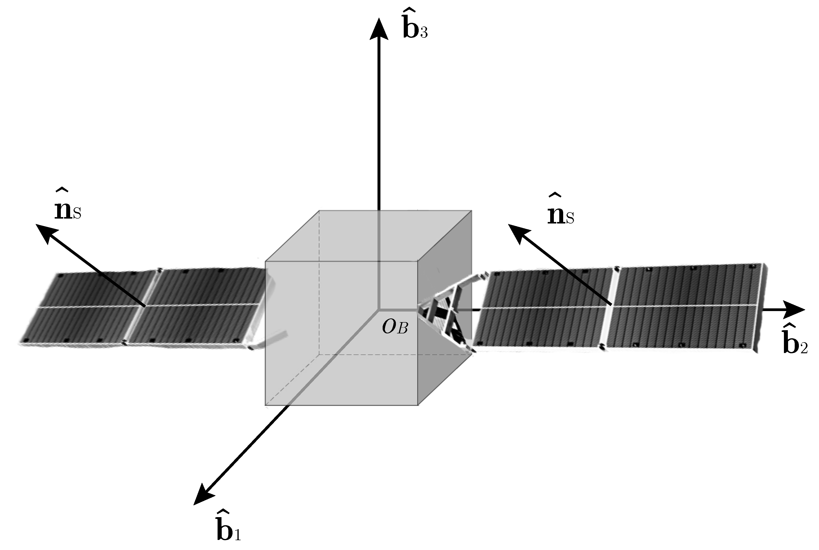
The research work considers a spacecraft orbiting around a planetary body, namely the Earth, whose generic configuration is shown in
Figure 1. The spacecraft attitude motion is described as the rotation of the rigid body frame,
B, with respect to an inertial reference frame,
I. Without loss of general applicability, the inertial reference frame can be selected to be an Earth-centered inertial (ECI) coordinate frame. In this paper, the
I frame coincides with the J2000 ECI reference frame, which is defined with the Earth’s mean equator and equinox at 12:00 terrestrial time on 1 January 2000 [
27]. The rigid body frame
B is centered in the spacecraft’s center of mass,
, and it is aligned with the spacecraft’s body axes,
,
and
. Without loss of generality, the solar arrays are aligned with
, and their normal direction,
, has components in
and
. Note that
is fixed in
B, since the research assumes no SADA to rotate the plane of the solar arrays.
The spacecraft attitude dynamics is described according to the Euler equation of rigid body motion as:
where
is the vector of spacecraft angular velocities, expressed in body frame and representing the rotation of
B with respect to
I.
is the inertia tensor of the spacecraft body, which is, in general, a full
matrix, because the axes of
B are not always coincident with the principal axes of inertia. Note that the inertia tensor is assumed to be constant in time (e.g.,
), since mass variations, flexibility effects, or component movements are not considered. Finally,
is the vector of disturbance torques, and
is the vector of control torques. The disturbance torques considered in this research work are due to both external and internal effects. They are modeled according to the international standards for system simulation and algorithms verification [
28,
29]. In particular, gravity, magnetic, atmospheric drag, radiation pressure torques are considered, as well as internal micro-vibrations induced torques and electro-magnetic interaction disturbances. The control torque is expressed in Equation (
1) according to the actuation device that is applying the control action to the system. The paper considers both momentum exchange devices and magnetic torquers as possible alternative actuators.
The momentum exchange devices are assumed to be reaction wheels, whose control action is executed by varying the spin rate of a rotating mass contained inside the spacecraft body. This assumption is motivated by analyzing existing space systems, being the reaction wheels the most common typology of momentum exchange actuators for spacecraft, either small or large classes. An
i-th reaction wheel applies a relative torque to a spacecraft thanks to the exchange of its angular momentum,
, with the main body. The angular momentum of the reaction wheel is expressed as:
where
is the moment of inertia of the
i-th reaction wheel around its spin axis, and
is the relative angular velocity of the
i-th wheel with respect to
B. With this formulation, the inertia of the non-spinning wheel is already included in the inertia tensor of the spacecraft,
, and Equation (
2) represents the additional angular momentum of the wheel due to its spinning state. To fully control the three-dimensional state of a spacecraft, at least three reaction wheels are needed, with the components of the spinning axes along any orthogonal body frame direction. Then, the overall angular momentum of
n identical reaction wheels becomes:
where
is a
matrix representing the
n spin axes in
B, and
is a column vector containing the spin rates of the
n wheels around their spin axes. Including the angular momentum exchange of the reaction wheels in Equation (
1) it can be seen that the control torque is applied to the system as:
where the actuation is executed by commanding a proper variation of the reaction wheel spin,
, which can be computed inverting the previous equation, knowing the desired control torque
.
The actuation by means of magnetic torquers, the control torque is generated by the interaction between a desired magnetic dipole moment,
, and an external magnetic field. In fact, magnetic torquers create a dipole moment by letting an electric current flow in electromagnetic coils, according to Ampère’s circuital law. Then, the control torque results in Equation (
1) as:
where
is the external magnetic field vector interfaced with the magnetic torquers. As evident from the previous equation, the magnetic torque is always perpendicular to both dipole moment and magnetic field vector. If the dipole moment can be in any desired direction, with at least three orthogonal magnetic torquers, the external magnetic field typically limits the feasible control torque directions. Namely, a magnetic control torque must lie in the plane orthogonal to
, and the system is under-actuated unless full actuation is achieved in an integral sense along an entire orbit [
30].
The control torque
is the final output of the proposed ADCS, which is applied to the system according to Equation (
4) or to Equation (
5), depending on the used actuation method. The torque
is computed with a pulse modulated PD control on the angle the Sun has with respect to the solar arrays. In fact, the solar arrays generate an electrical current almost proportional to the cosine of the Sun angle with respect to the sensor normal,
, as:
where
is the maximum current produced when the Sun is perfectly perpendicular above the solar arrays, being
expressed as:
where
is the Sun direction unit vector, as seen in body frame
B. Thus, the solar arrays are correctly oriented to the Sun, producing the maximum electric power, when:
Note that
since the angle direction is unknown, and the domain of the angle is
. The PD control is designed to have a null
angle, being:
where
is a function of the Sun angle that is equal to zero whenever
, or
;
is the control modulation term, which defines the control axis according to a pulsed modulation sequence;
and
are positive scalar gains. The proportional action drives the solar arrays to be aligned with the Sun, with a derivative term directly dependent from the angular velocity of the spacecraft. Inserting Equation (
9) in Equation (
1), and neglecting the disturbance torques, the dynamics can be expressed as:
which has an equilibrium point only for
and
. Note that this control formulation assumes the Sun as fixed in the inertial reference frame. This assumption is motivated by the slow rotation of the Sun, as seen from the ECI, when compared with the characteristic time of the rotational dynamics of the spacecraft. The PD control structure is motivated since the proposed algorithms are inherently proportional to the Sun angle, with derivative terms given by the angular rates. Being the proportional term direction not completely known in three-dimensional space, the steady-state error cannot be asymptotically eliminated. Thus, the integrator term cannot be directly included in the present control structure. Moreover, the presence of the integrator term would reduce the stability of the closed-loop system.
2.1. Attitude Determination and Control Architecture
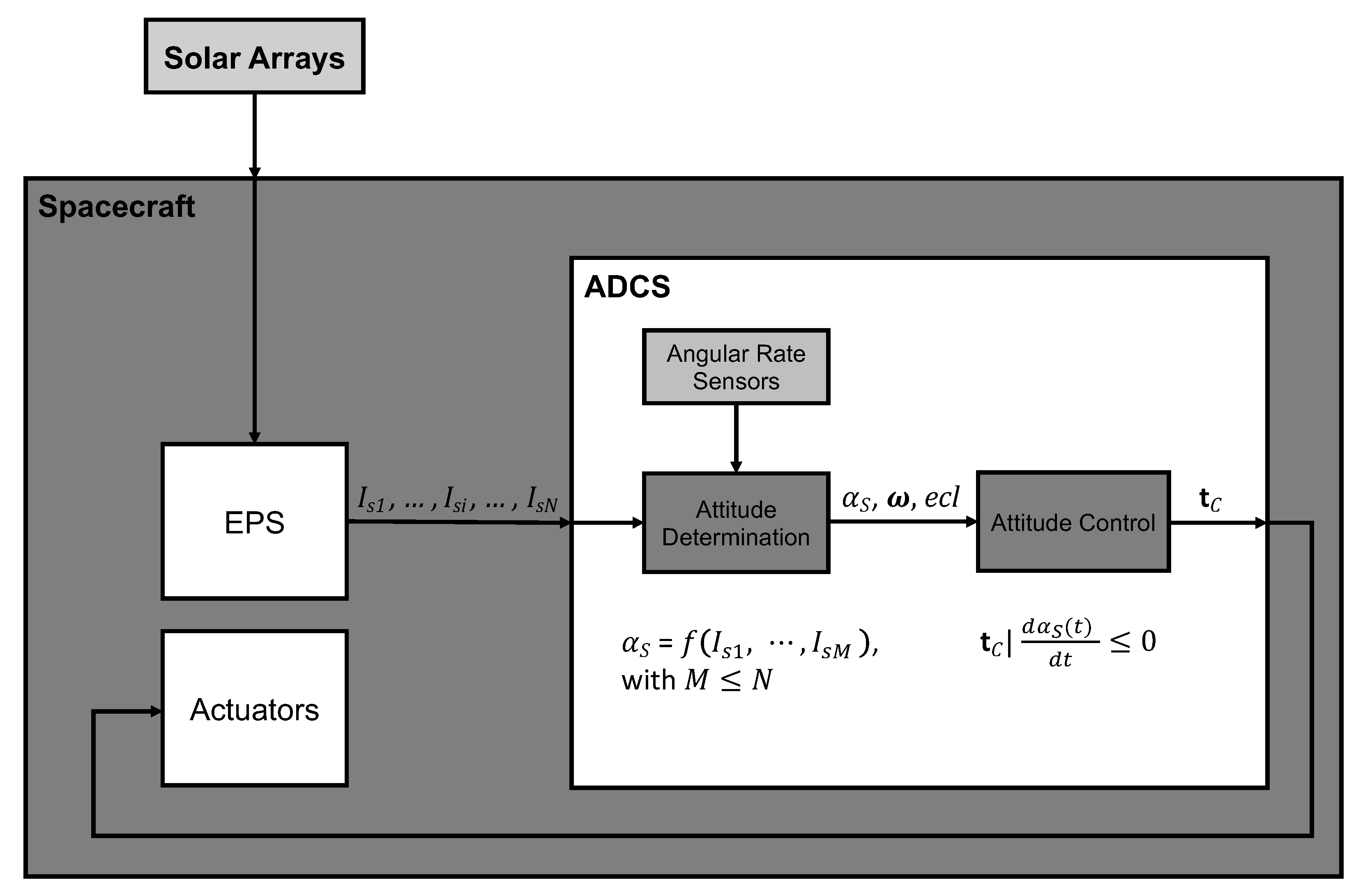
The attitude determination and control architecture is implemented to guarantee the correct execution of the proposed attitude determination and control subsystem. The proposed ADCS architecture scheme is reported in
Figure 2 highlighting the main data interfaces at the element level, and the algorithm process. The ADCS algorithm is sequential and continuously running whenever the system is active. The subsystem architecture foresees a close integration of the ADCS with the electrical power subsystem (EPS) of the spacecraft, which is responsible for the management of the solar arrays and the generation of the associated telemetry data. In fact, the power generation of the solar arrays is subjected to a closed-loop control action from the EPS to have proper regulation and conditioning of the incoming electrical current. Moreover, the solar arrays may be subdivided into different sections or strings, and multiple current readings may be available. Anyhow,
N current measurements from independent groups of solar cells,
, shall be available for the ADCS processing. Each current value must be associated with a group of primary solar cells with a unique
.
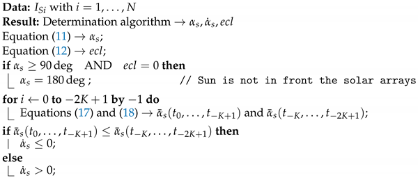
The ADCS processes these data to obtain the Sun angle with respect to the primary solar arrays:
This is done by knowing the way in which the solar cells are grouped and oriented. The maximum current values for each group of solar cells,
, shall be known by ground characterization and testing. Moreover, these parameters could be also updated along the mission lifetime in a way to re-calibrate the algorithms and account for solar arrays degradation and aging. Although, it shall be noted that the proposed algorithm is not very sensitive to a calibration error in these values, being the control logic designed to minimize the Sun angle. In fact, a wrong value for
would result in the algorithm not reaching
, but a different minimum numerical value, always associated with the maximum power generation. The sole negative effect is associated with slightly larger oscillations around the correct pointing state. This is due to a non-exact scaling term
. Furthermore, relative errors between different groups of solar cells are not relevant since they are averaged along the process in Equation (
11), and they are associated with a single normal direction.
The electric measurements of secondary solar panels,
with
(i.e., solar cells aligned in other directions), are not directly used from the ADCS and Equation (
11), but they can be exploited together with the primary measurements to detect if the spacecraft is currently shadowed by the Earth and no Sun pointing shall be commanded. In fact, the ADCS shall be capable to detect the eclipse condition and issuing an eclipse flag,
. The proposed algorithms achieve this by comparing the overall power generation of all the available solar cells with respect to a minimum threshold:
where
is a calibration parameter very close to zero to reduce the number of false eclipse events. Moreover, the presence of solar cells shall not leave uncovered directions. If this is not the case, or if no secondary solar cell is available, the eclipse condition shall be detected on-board with a proper orbital model or GNSS sensor, or by exploiting Sun presence sensors placed on the external surfaces of the spacecraft. When the eclipse flag is active, the proportional term of the control in Equation (
9) is set equal to zero, and the control is only proportional to the angular velocity to maintain the inertial position of the spacecraft until the Sun is back in view. A wrong eclipse condition would not set the spacecraft in danger since, after a predefined eclipse windows time, the system would receive a warning and a complete Sun searching rotation would be performed. The ADCS shall be also equipped with angular rate sensors, such as gyroscopes, or magnetometers with angular rate estimation methods [
31]. This is necessary to have an estimation of the angular velocity of the spacecraft,
, which is needed to compute the derivative action of the control in Equation (
9).
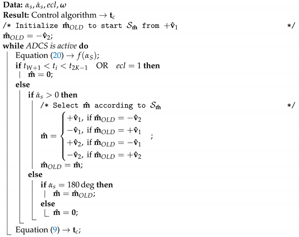
The control section processes the Sun angle, the angular rates, and the eclipse flag to obtain the control torque capable to minimize
. The control algorithm assesses the variation of
and modulates the proportional term of the control with the modulation vector,
. The modulation vector selects the body axis around which the rotation shall be performed to minimize
as:
where
and
are two orthogonal direction unit vectors in body frame. In order to align the solar arrays to the Sun, both
and
shall be orthogonal to
. For instance, with reference to
Figure 1,
and
may be selected as:
Note how the rotation around is not controlled since it is not relevant to achieve the pointing of the solar arrays. The control algorithm modulates the proportional control action by searching for the right according to the time variation of (i.e., ). This is done with a pulsed sequence spanning the possible values of until the Sun angle is increasing. When the time derivative of is non-positive, the proportional term is zeroed, being , and the system evolves under the derivative action control until the Sun angle decreases. Between two control pulses, the proportional control is zeroed to have some time to detect the effect of the last control action. Moreover, when the Sun is not in front of the primary Solar arrays, the pulsed modulation is maintained with the last commanded direction to perform even a full rotation until the Sun is in view of the Solar panels. In this case, to account for possible eclipses not detected, the Sun searching rotation would be performed up to two times around two different axes. If the Sun is not yet in view, the system is posed in eclipse mode with a warning, until the Sun is visible again or the maximum eclipse time has passed.
The specific algorithms implementation shall consider the noise in the measurements and the disturbances affecting the dynamics. Hence, the Sun angle variation is detected over a finite interval of time, to be synchronized with the pulse frequency, to have an integral overview of the dynamics.
4. MIL Verification
The proposed solar arrays and angular rates only ADCS has been developed for practical applications in real space software and hardware. Then, the verification of the control performance has been carried out with model-in-the-loop testing campaigns, exploiting a functional engineering simulator (FES) developed for small satellite applications in Earth orbits. In particular, the spacecraft considered in the verification campaign has moments of inertia in the order of , dimensions of a CubeSat and solar arrays producing a maximum power of W. The MIL results are analyzed and discussed in terms of generated power from the solar arrays, being the primary objective of the proposed ADCS. Moreover, a direct relationship between the power generation and the Sun angle is available. The actuators considered in the simulations are reaction wheels with a maximum torque of , or magnetic torquers with a maximum dipole moment of . The MIL verification exploited Monte Carlo analyses with dispersion on the simulation parameters. The verification has been conducted on more than 500 runs, but a reduced subset of the worst-performing 10 samples is reported in the figures of this paper. The simulation parameters affected by dispersion are all the initial conditions for the dynamics, the inertia, the position of the center of mass, the ballistic and the reflectivity coefficients, the measurement noise, the actuators errors. The dispersion is random at 50% of the nominal value at for normal distributions, and at 25%
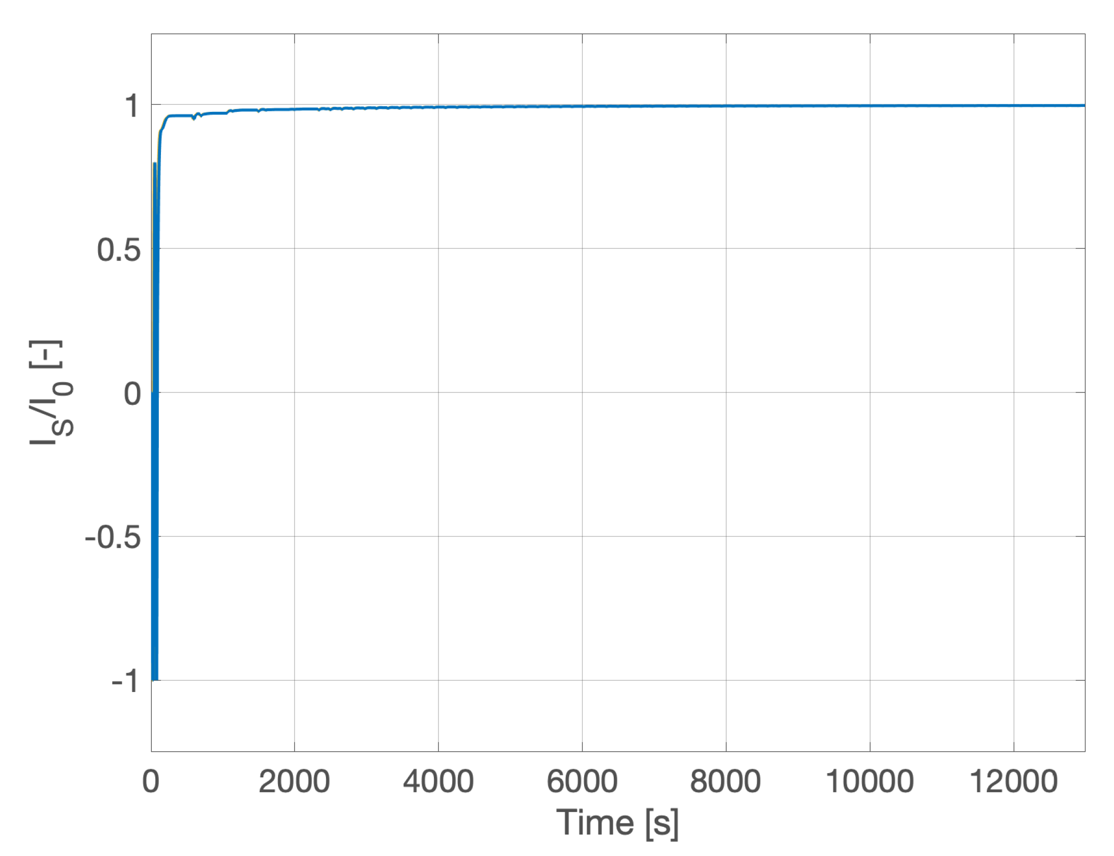
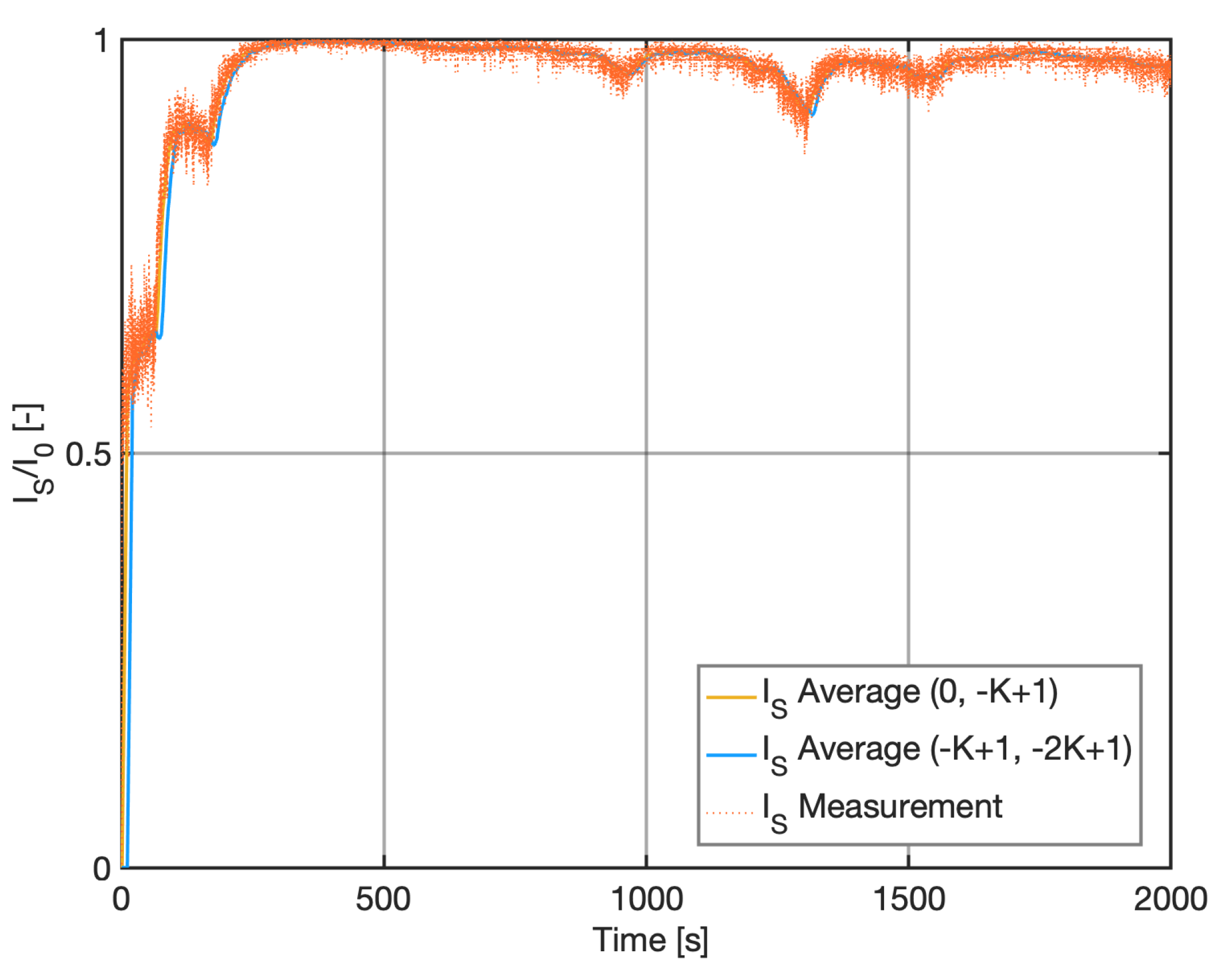
The effect of measurement noise is shown in
Figure 7, where the input and the output of the attitude determination algorithms are reported. For coherence with all the results shown in this paper, the specific current is shown in the figure. Reminding Equation (
8), a specific current equal to 1 corresponds to aligned solar arrays, with Sun angle equal to 0. The noisy current measurements are averaged over the last two batches of
K samples to detect a rising or decreasing trend in the Sun angle. The output of the attitude determination is the two smoothed lines, whose direct numerical comparison allows the estimation of the derivative of the Sun angle, as discussed in the determination algorithm section.
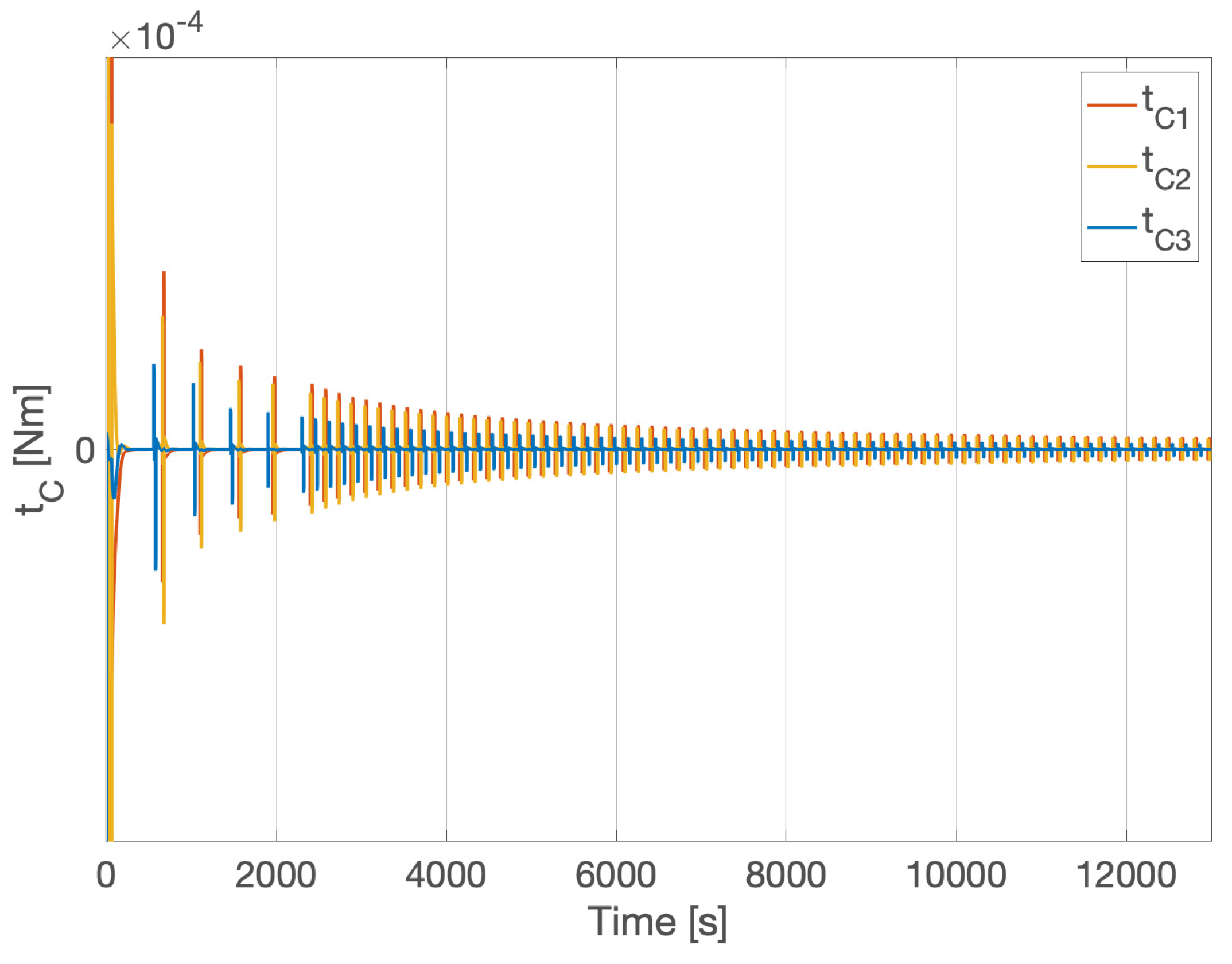
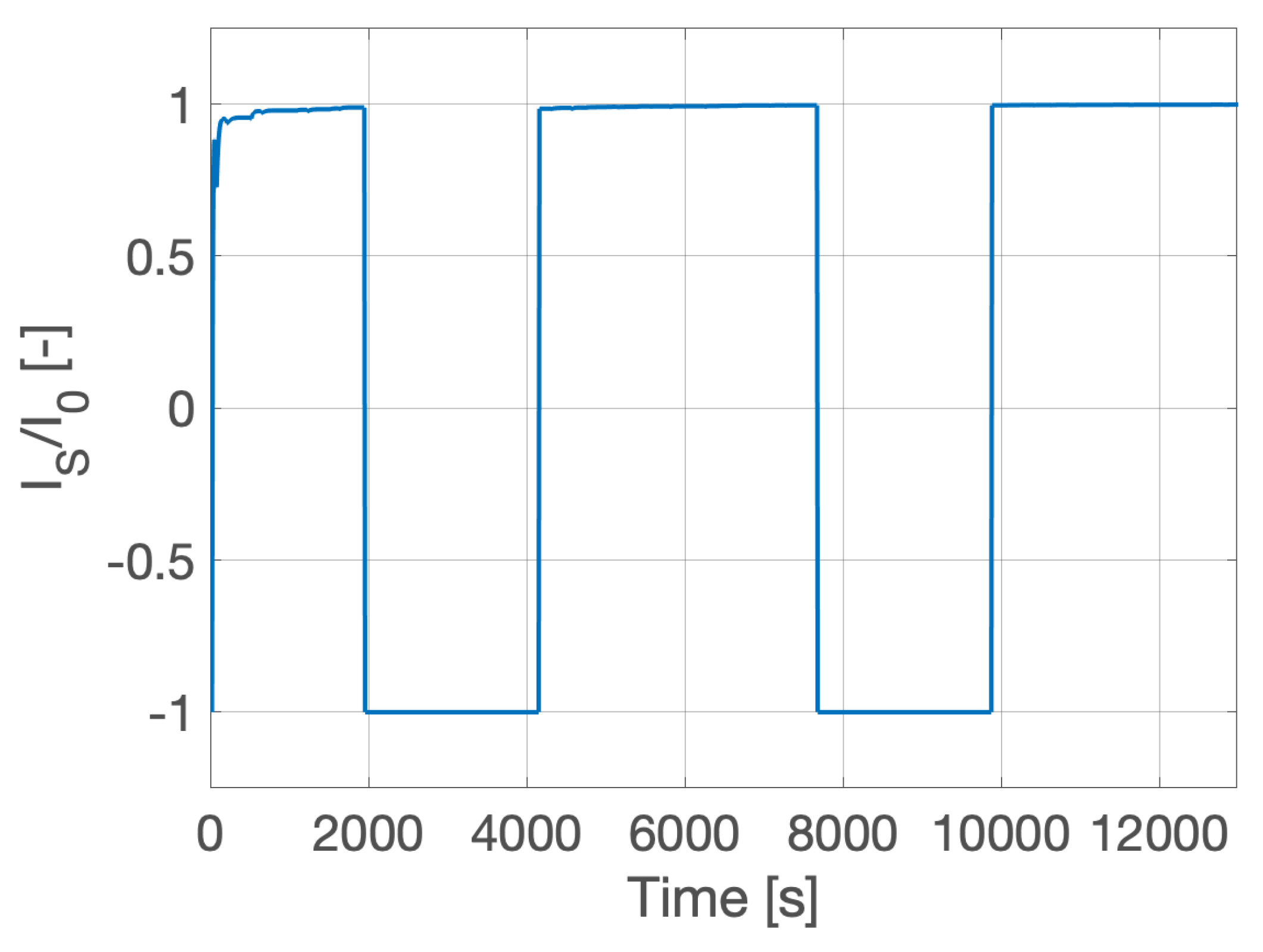
4.1. Momentum Exchange Actuation
The verification of the solar arrays pointing ADCS exploiting momentum exchange actuation with reaction wheels is reported in
Figure 8 and
Figure 9. The simulations are on the two orbital typologies introduced above: an equatorial orbit with eclipses, and a Sun-synchronous orbit with LTAN at 06:00. The simulation time in the plots corresponds to 2 orbital periods. In both cases, the Sun pointing is always achieved in less than
min, and few brief deviations with respect to the nominal optimal pointing are only present in the very worst scenarios. In all the cases the Sun is never lost from the front of the Solar arrays. The average produced power is ∼30 W, which corresponds to ∼93% of the maximum power. Note that the computation of the average produced power does not account for the eclipse periods.
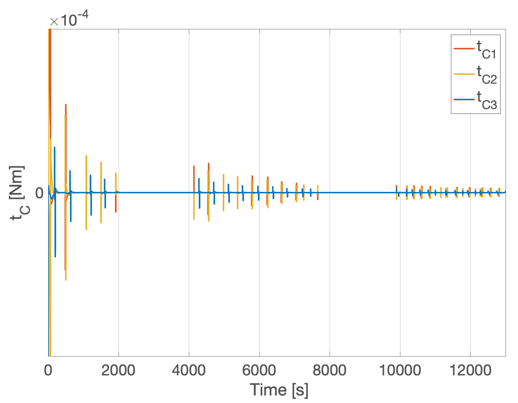
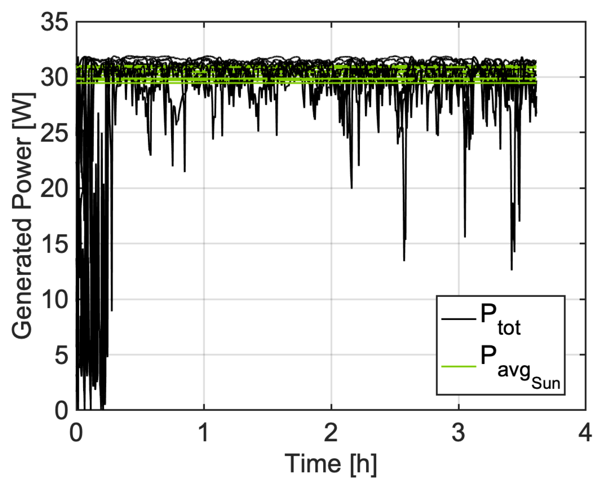
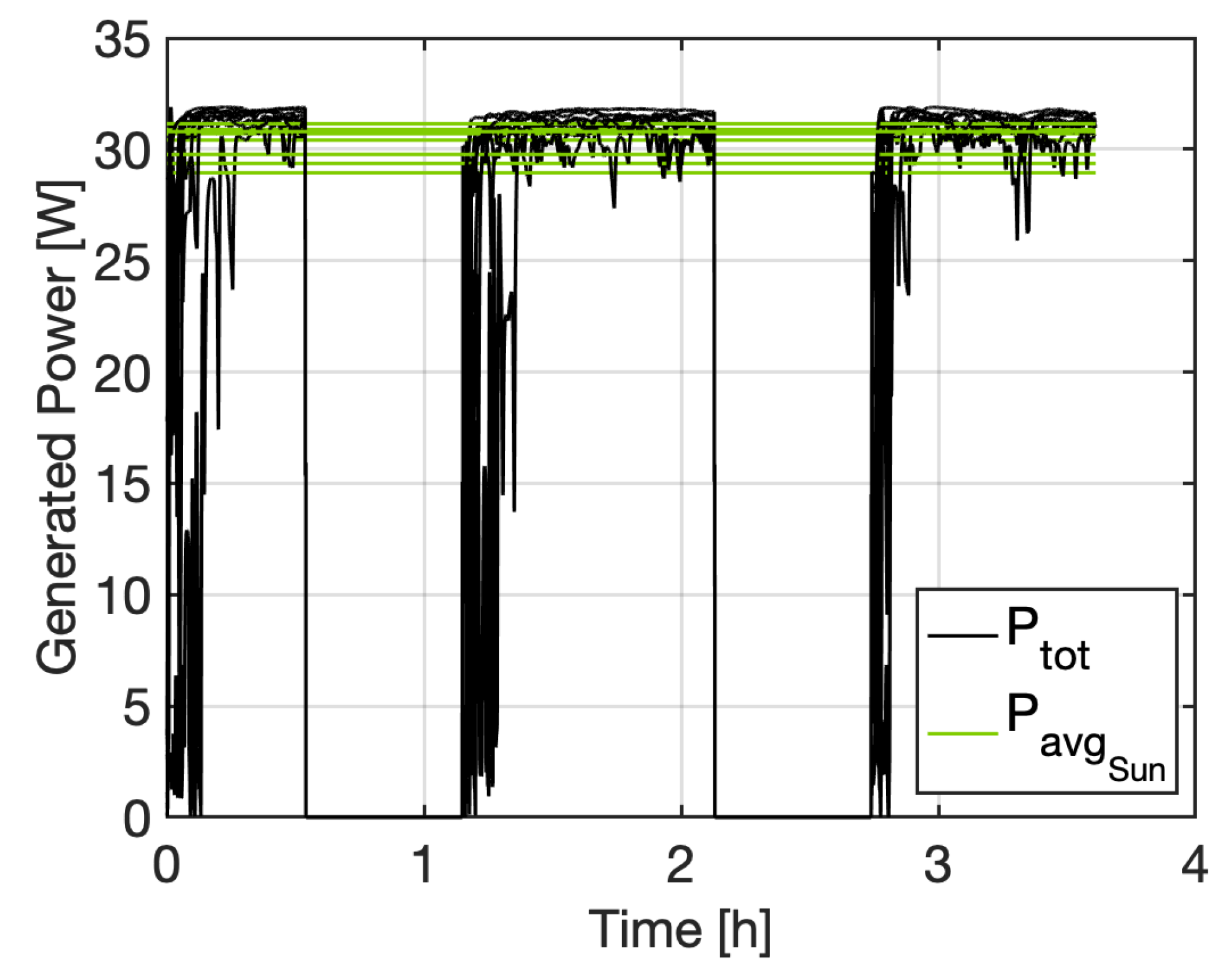
4.2. Magnetic Actuation
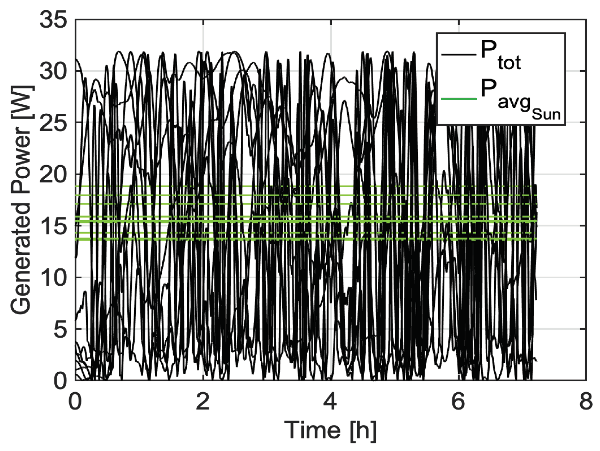
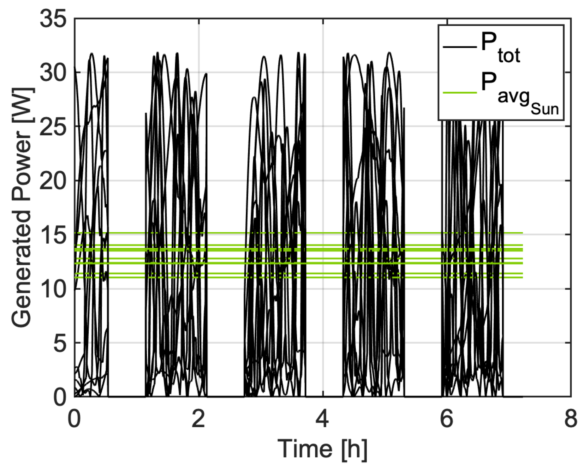
The verification of the solar arrays pointing ADCS exploiting magnetic actuation with magnetic torquers is reported in
Figure 10 and
Figure 11. In these cases, the ADCS seems to be completely ineffective, and not capable to reach a stable Sun pointing. This is partially true, and it can be explained by reminding that the magnetic actuation is constrained to lie in the plane orthogonal to the external magnetic field vector. Hence, the control direction commanded by the pulsed modulation vector
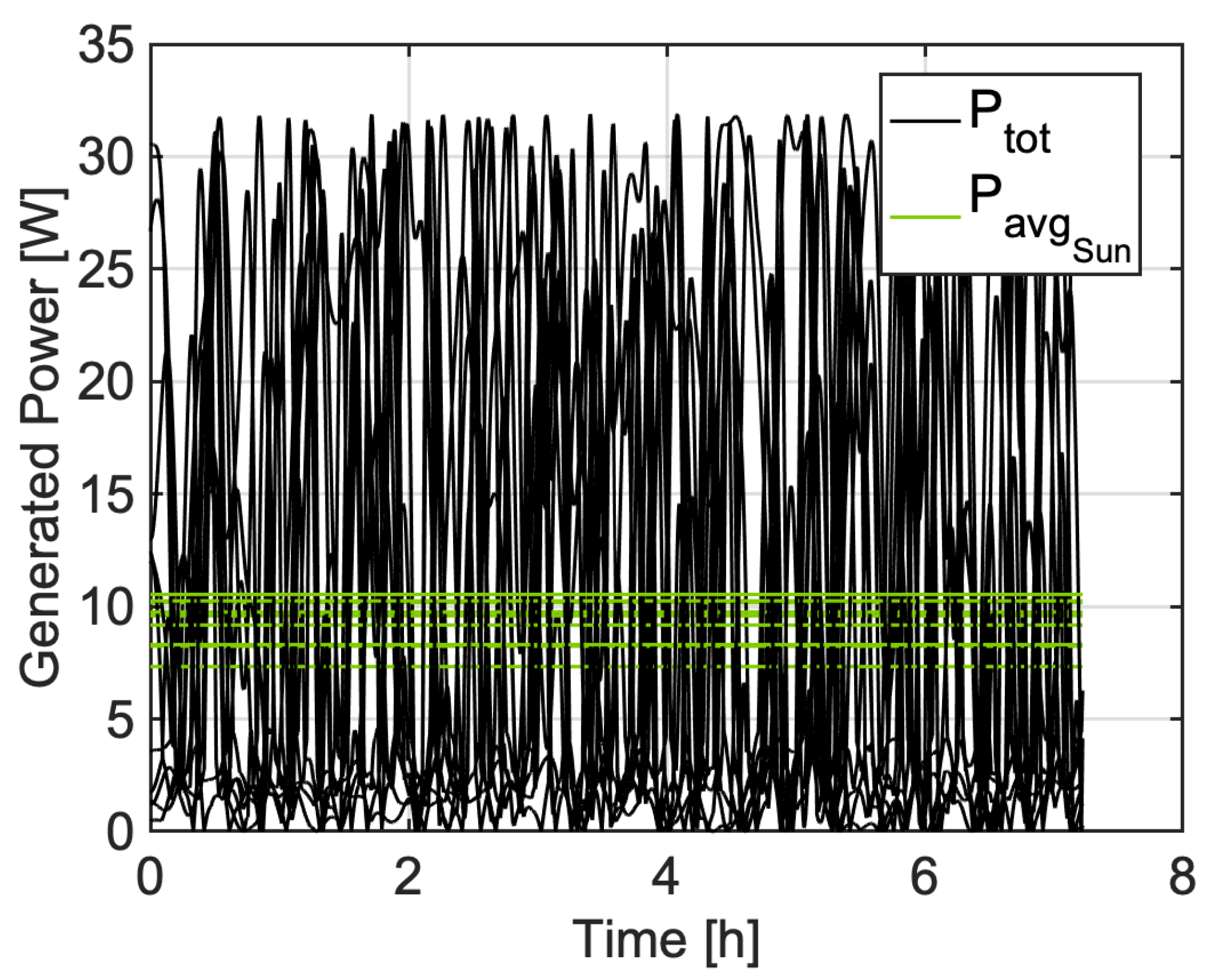
is in general not feasible. As a consequence, the under-actuation of magnetic torquers is an issue for the proposed ADCS, and this typology of actuators is not suitable for this pulsed modulation scheme. However, comparing the non-controlled case in
Figure 12, the average produced power increases when the magnetic control is active. In fact, when the system is not controlled, the average produced power is
W, while it gets to 15–
W in
Figure 10 and 10–
W in
Figure 11. This corresponds to an improvement of 100% in Sun-synchronous orbits, and 50% in equatorial orbits. This difference between the two typologies of orbits is expected since the magnetic actuation is particularly low performing in an equatorial orbit. In fact, being the equatorial plane almost parallel to the magnetic equator, the control torque is constrained to lie on this plane. Therefore, the rotation around the body axis aligned with the north pole direction of the ECI is almost never possible. This has a dramatic influence on the available control performance with magnetic actuation in Earth equatorial orbits. In general, the solar arrays and angular rates only ADCS is not capable to achieve a stable Sun pointing with magnetic actuation methods. Although, the proposed control method is slightly effective in improving the electric power generation with respect to a non-controlled case. This result may be mitigated by integrating both magnetic torquers and other actuation methods, even if partially failed or not complete. For instance, the presence of a single reaction wheel with components in all the three body axes of the spacecraft might help to solve the controllability problem with magnetic actuation methods.


