Article

A Computational Approach to Overtaking Station Track Layout Design Using Graphs: An Extension That Supports Special Turnouts—An Improved Alternative Track Layout Proposal

by
Eugenio Roanes-Lozano
Instituto de Matemática Interdisciplinar (IMI) & Depto. de Didáctica de Ciencias Experimentales, Sociales y Matemáticas, Facultad de Educación-Centro de Formación del Profesorado, Universidad Complutense de Madrid, c/ Rector Royo Villanova, 1, 28040 Madrid, Spain
Algorithms 2022, 15(10), 368; https://doi.org/10.3390/a15100368
Submission received: 12 August 2022 / Revised: 28 September 2022 / Accepted: 29 September 2022 / Published: 3 October 2022

Abstract

:
The author recently designed, developed and implemented in Maple a package based on the use of digraphs that analyses the connectivity of an overtaking station on a double-track line. It was used to propose an alternative track layout for this kind of station, with advantages over the track layouts usually adopted. However, that package could only deal with “standard” turnouts (but neither with crossings nor with “special” turnouts, such as “single slip turnouts” or “scissors crossings”). This new article presents an improved version of the package. It uses a trick consisting in including virtual vertices in the associated digraph that are dead ends. This way it is possible to include the “special” turnouts in the track layout. It makes it possible to evaluate different alternative track layouts, including “special” turnouts; and to finally find one track layout that has advantages over the standard one and over the one proposed in the previous article. Let us observe that the design of the track layout is key for the exploitation of the infrastructure. In fact, the Spanish infrastructure administrator is nowadays remodelling the track layout of some of its main railway stations, as well as other smaller facilities.

1. Introduction

1.1. Preliminary Railway Concepts

Railways are guided transportation systems. Trains run on tracks; they can move from one track to another only at some specific places where a device called “turnout”, with a mobile part denoted “switch”, is installed (note that in American English they are named “railroad switch” and “point”, respectively). The switch of a turnout can be in two positions: “direct track” and “diverted track” [1] (see Figure 1).
Railway traffic is controlled by light signals (see Figure 2), although old mechanical signals can still be found in many lines around the world. They are remotely controlled from rooms or buildings called “signal boxes” (“interlocking towers” in American English). All the train engineer has to do is read the signals and obey them.
Traffic lights in roads change colour after fixed periods. Stopping a train takes a long distance; thus, safety is not based on time, but on booking space for the trains (sections of the track layout of the station or sections of the railway line) [1,2].
Moreover, human errors must be avoided; therefore, the logical compatibility of the position of the switches of the turnouts and the colour of the light signals (stop/proceed) is supervised by a device called “railway interlocking systems” that does not allow conflictive configurations to be set. They were initially mechanic, later based on the use of relays, and now computer-based.

1.2. Related Previous Works

“Overtaking stations” are stations on double-track lines with sidings on each of the two sides of the main line; and one or two, or more crossovers at the two throats of the overtaking station [3] (Figure 3 and Figure 4). Almost all the small overtaking stations on double-track lines have the same track layouts everywhere (sometimes with fewer crossovers); they can be found on high-speed lines of countries such as Japan, France, Spain, etc. [4], as well as on classic lines (in fact, the track layouts of Figure 3 and Figure 4 are considered standards in [4] (p. 155)). Observe that we are not considering in the track layout diagrams the frequently used dead-end sidings included for safety reasons; this is because they do not add anything to the connectivity of the station, which is the goal of this article.
The author is a mathematician and computer scientist with a long experience in the design, development, and implementation of software for railways. Some of these works [5] have been developed in cooperation with or commissioned by the “Fundación de los Ferrocarriles Españoles” (Spanish Railway Foundation) [6].
Regarding track layout design [7], he implemented in the computer algebra system (CAS) [8,9] Maple (Maple is a trademark of Waterloo Maple Inc.) [10,11,12,13] a small topology-independent package [14] based on the use of cycles in an undirected graph [15]; which could find compatible routes in overtaking stations on double-track lines (of any topology). Let us observe that the compatibility of routes has to be very carefully checked during the design of a railway interlocking system.
A collateral result found was the existence of an alternative track layout for small overtaking stations on double-track lines (Figure 5), with advantages and disadvantages over the standard track layout. The disadvantage is that only half of the tracks are reachable from each throat of the station. The advantage is that section 0 allows to maintain a bidirectional use of the station on a degraded scenario where the tracks on one side of the main line are unavailable.
The next goal was to design, develop, and implement an ad hoc package focused on comparing different track layouts of overtaking stations on a double-track line (of any topology) [16]. The software chosen was also Maple. The key idea was to compare alternative track layouts and to calculate the number of pairs of non-conflicting routes (one in each direction) in each case; simulating the ones that could be simultaneously authorized by a railway interlocking system.
The approach in [16] was not based upon looking for cycles (that was the strategy in [14]) and directed graphs were used instead of graphs (in order to avoid considering trains going forward and backward). Note that using digraphs did not condition the movements of the trains: the routes were always considered from the same throat of the station to the other throat (despite the trains traversed the routes in one direction or the other; as the key fact is that the routes, considered as sets of sections, are disjoint).
The package developed, denoted Estaciones, was based on Maple’s GraphTheory package [17,18]; it made extensive use of its commands IsReachable and ShortestPath. The main procedures of the package Estaciones are: IsReachableThrough, NumberTrailsExceptThrough, ShortestPathThrough and TotalNumberTrailsExceptThrough, the names of which clearly reveal their purpose.
In [16], it was shown that the traditional railway station track layout of a small overtaking station on a double-track line (Figure 4) is not optimal. In fact, the alternative layout of Figure 6 has clear advantages over the traditional one (Figure 4) in degraded scenarios.
A restriction of the approach proposed in [16] was that that Estaciones package could only deal with “standard” turnouts; and neither with crossings nor with “special” turnouts, such as “single slip turnouts” and “scissors crossings” (see Section 2).

2. Materials and Methods

Railway station track layout is an important issue. For instance, the Spanish infrastructure administrator (Adif) [19] is modifying the track layouts of the two main stations of Madrid (Madrid Chamartín [20,21] and Madrid Atocha [22]), Barcelona Sants [23,24], and Sevilla Santa Justa [25]; as well as several other minor facilities [26,27]. Most of the latter ones are overtaking stations that are similar to those in Figure 3 and Figure 4; or passing loops or small stations with sidings on single-track lines. In fact, some Spanish railway authorities are interested in our works.

2.1. The “Special” Turnouts

The track apparatuses are not restricted to turnouts, although they are the most frequently used by far. We could underline:
  • crossings, the simplest, that allow two tracks to cross; without allowing to switch tracks (there are no mobile parts);
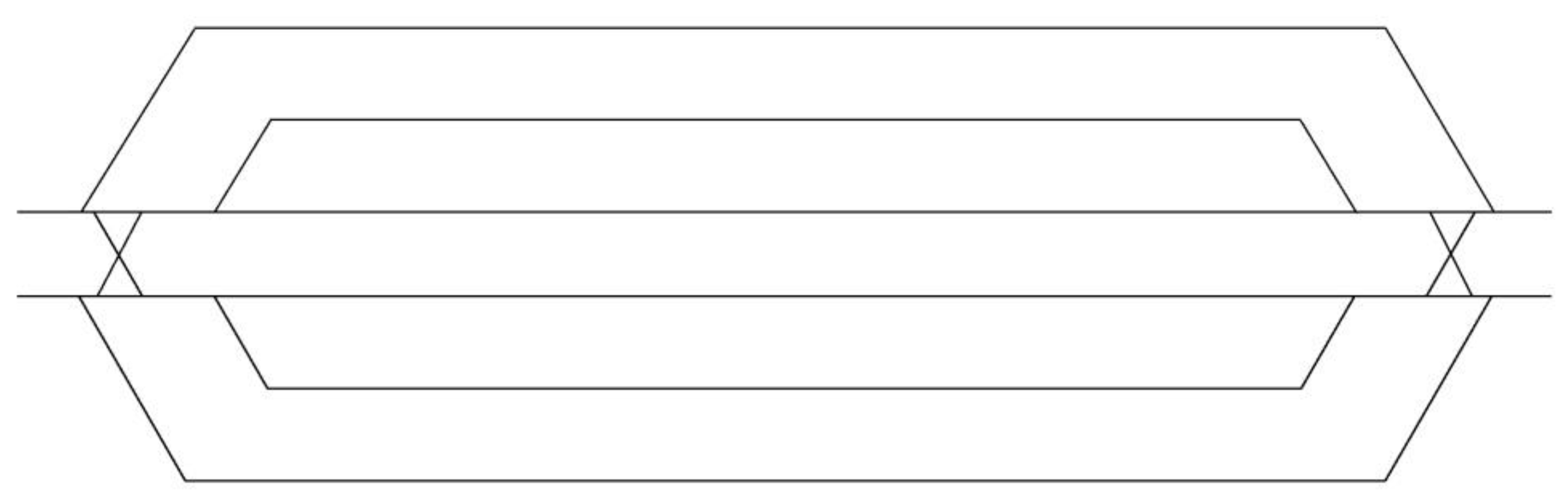
  • double-slip turnouts, that allow two tracks to cross; also allowing to switch tracks from each end of the two tracks, something such as two overlapping opposite turnouts (Figure 7);
  • single-slip turnouts, that allow two tracks to cross; also allowing to switch tracks, but just from one of the two ends at each side of the apparatus; something such as half a crossing and an overlapping turnout;
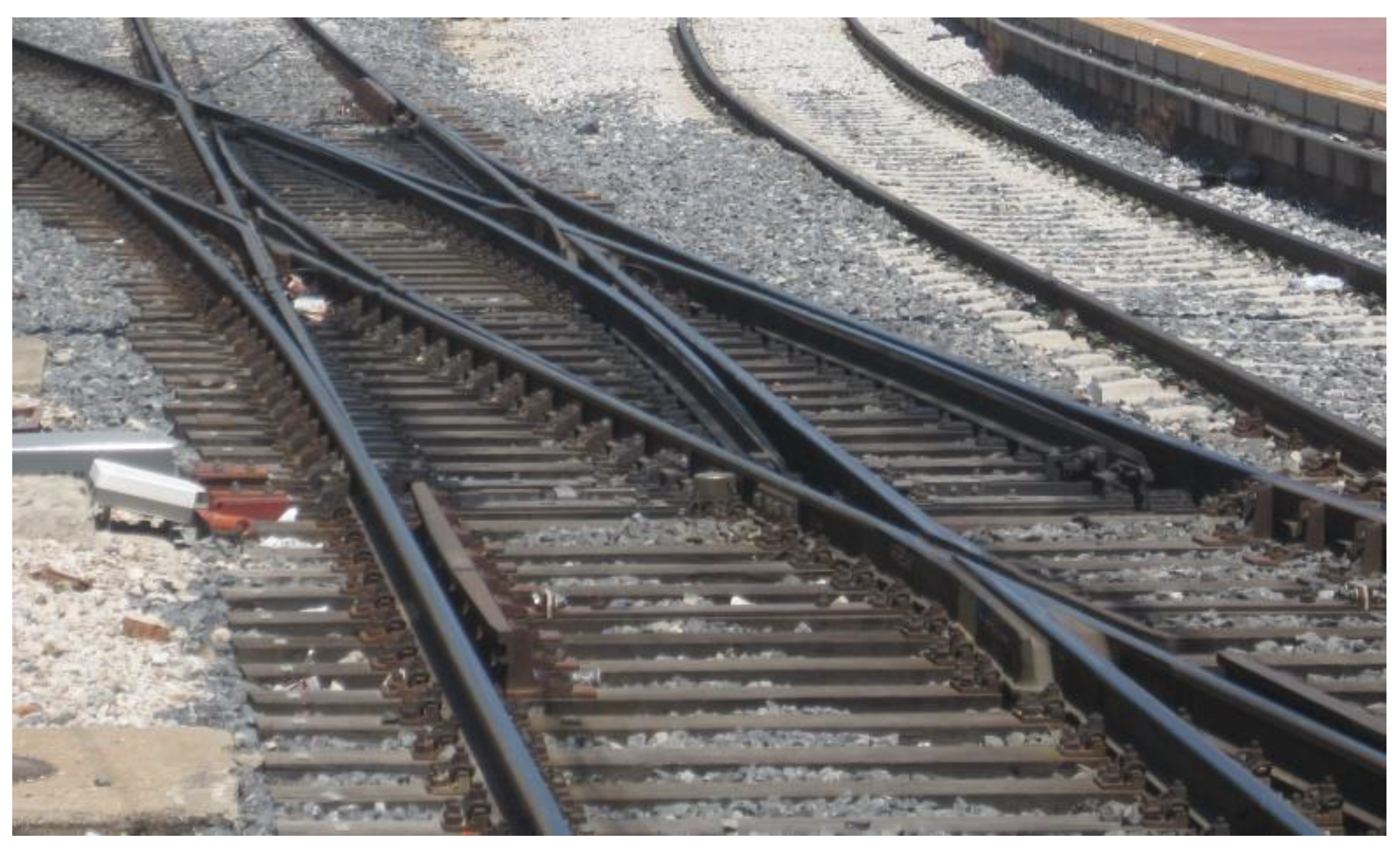
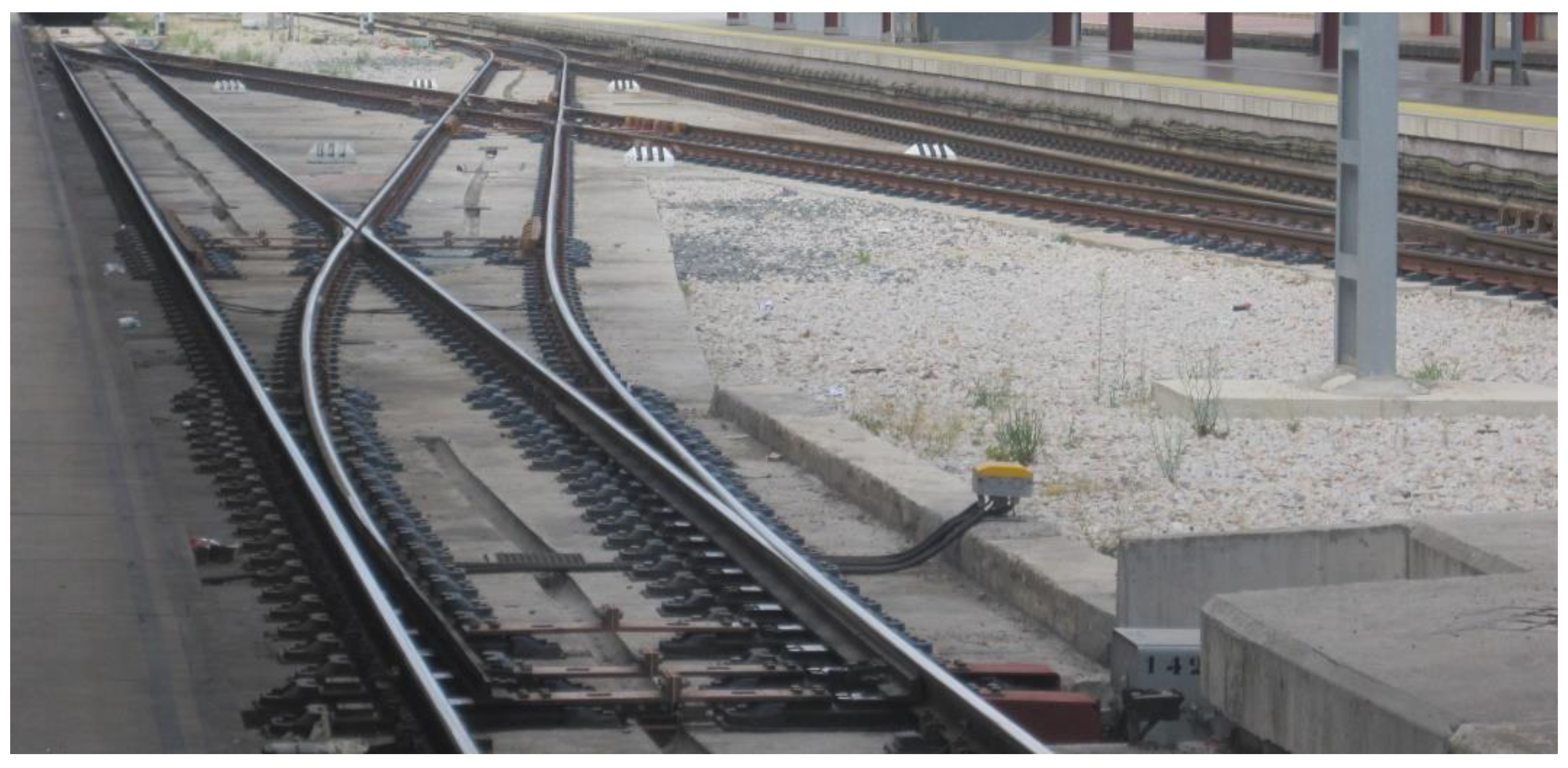
  • scissors crossings, a set consisting of four turnouts and a crossing (Figure 8).

2.2. The Approach of Estaciones Package

Let us apply the approach of Estaciones package [16] to the track layout diagram of Figure 4. The track is firstly divided into sections and names are assigned to them (Figure 9). Then, a digraph reflecting the connectivity of the station (from one throat to the other) is constructed (Figure 10).
Unfortunately, the Estaciones package cannot handle all the “special” turnouts (only the double-slip turnout). Let us consider afterwards, for instance, a scissors crossover.

2.3. Unsuccessful Attempts to Handle a Scissors Crossover

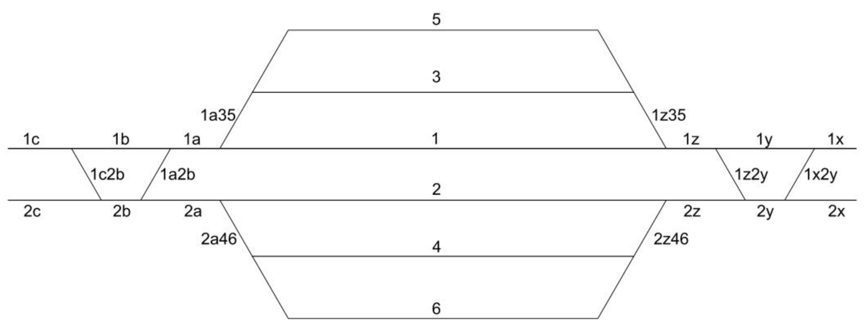
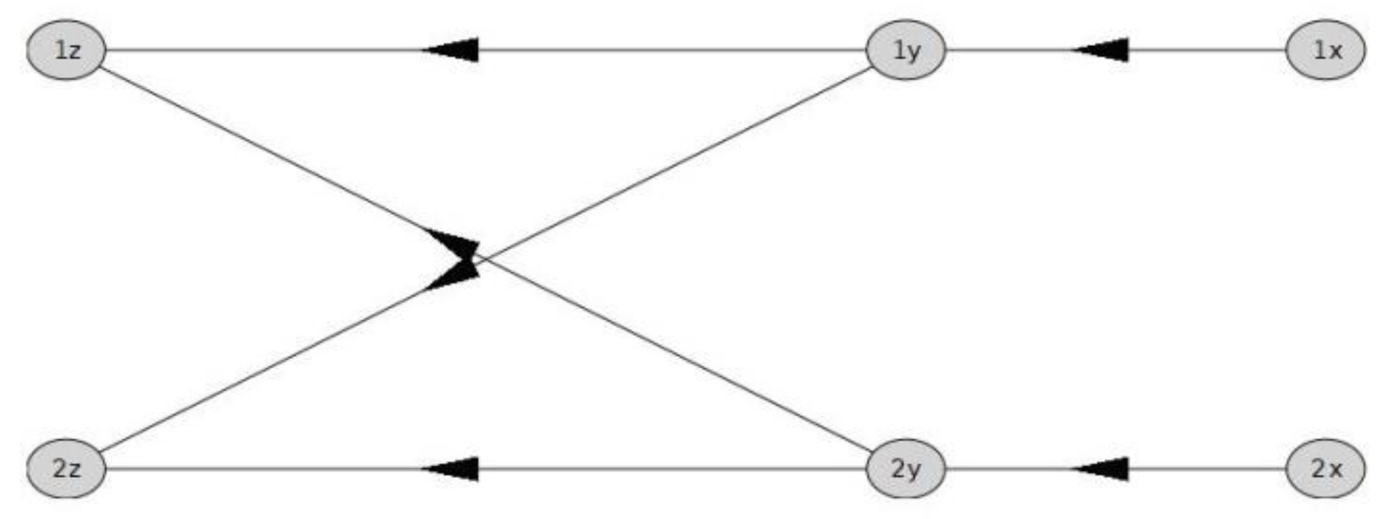
  • First attempt: the crossing in the scissors crossing is represented by two directed arcs: (1y,2z) and (2y,1z) (Figure 11).
  • The connectivity of the scissors crossing is correctly represented in the digraph; however, there is no way to detect whether the two routes intersect or not at the crossing.
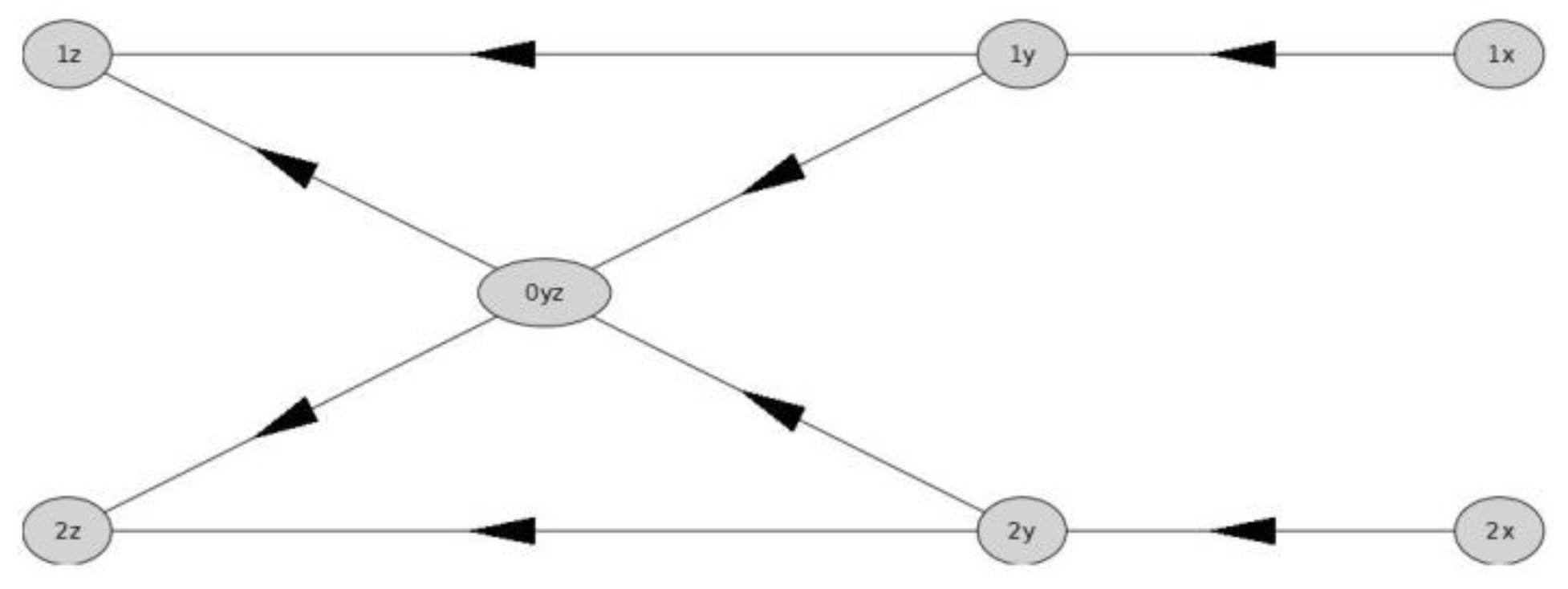
  • Second attempt: a new vertex, denoted, for instance, 0yz, is included at the center of the scissors crossing (Figure 12); and the directed arcs (1y,2z) and (2y,1z) are substituted by (1y,0yz), (0yz,2z), (2y,0yz), and (0yz,1z). This way, it is straightforward to detect whether the two routes intersect or not at the crossing (just checking whether vertex 0yz belongs to both routes or not). Unfortunately, the connectivity of the digraph would not be correct, allowing, for instance, the route 1y→0yz→1z if there was a problem in the directed arc (1y,1z); as if the crossing was a double-slip turnout (which, by the way, would be absurd here to install and impossible to install—due to the short length of the crossing).

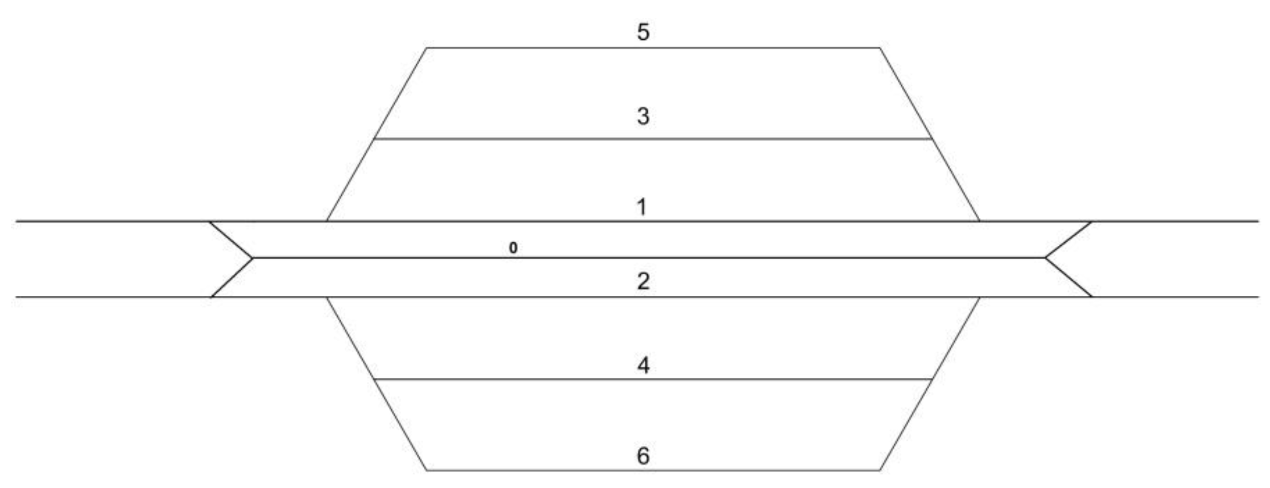
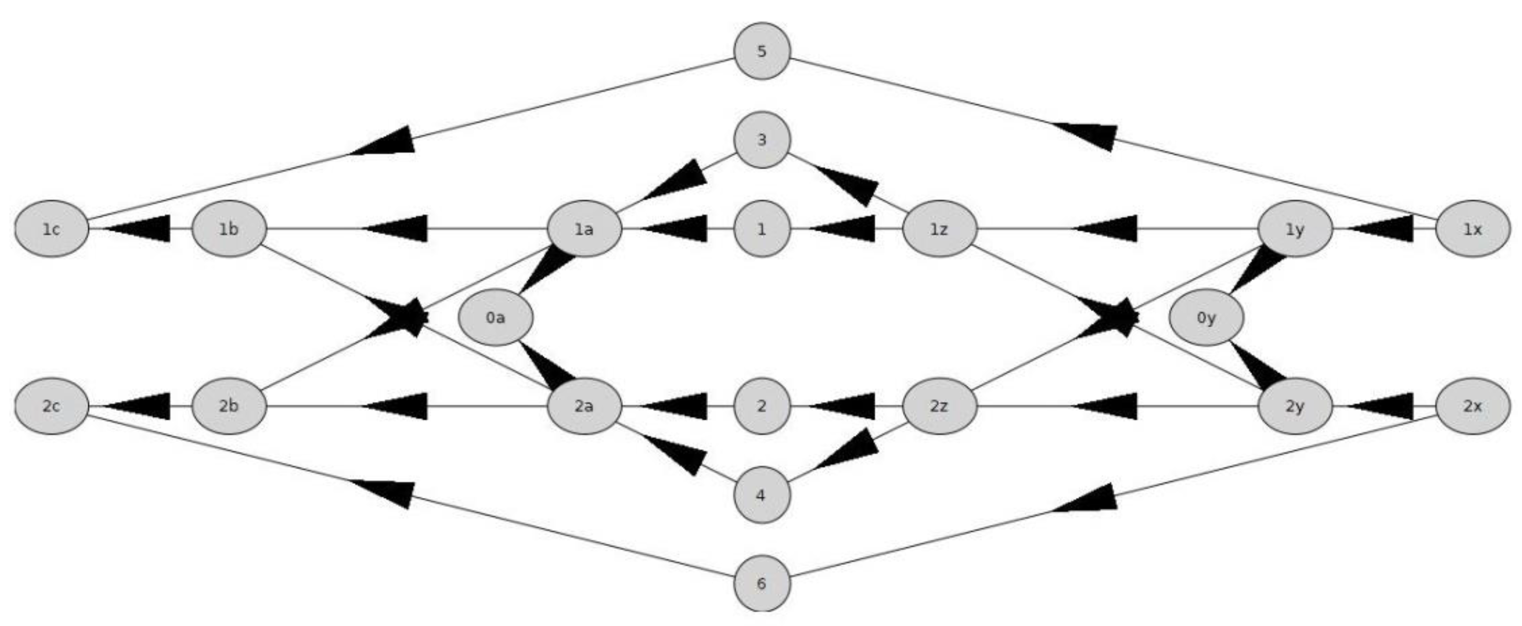
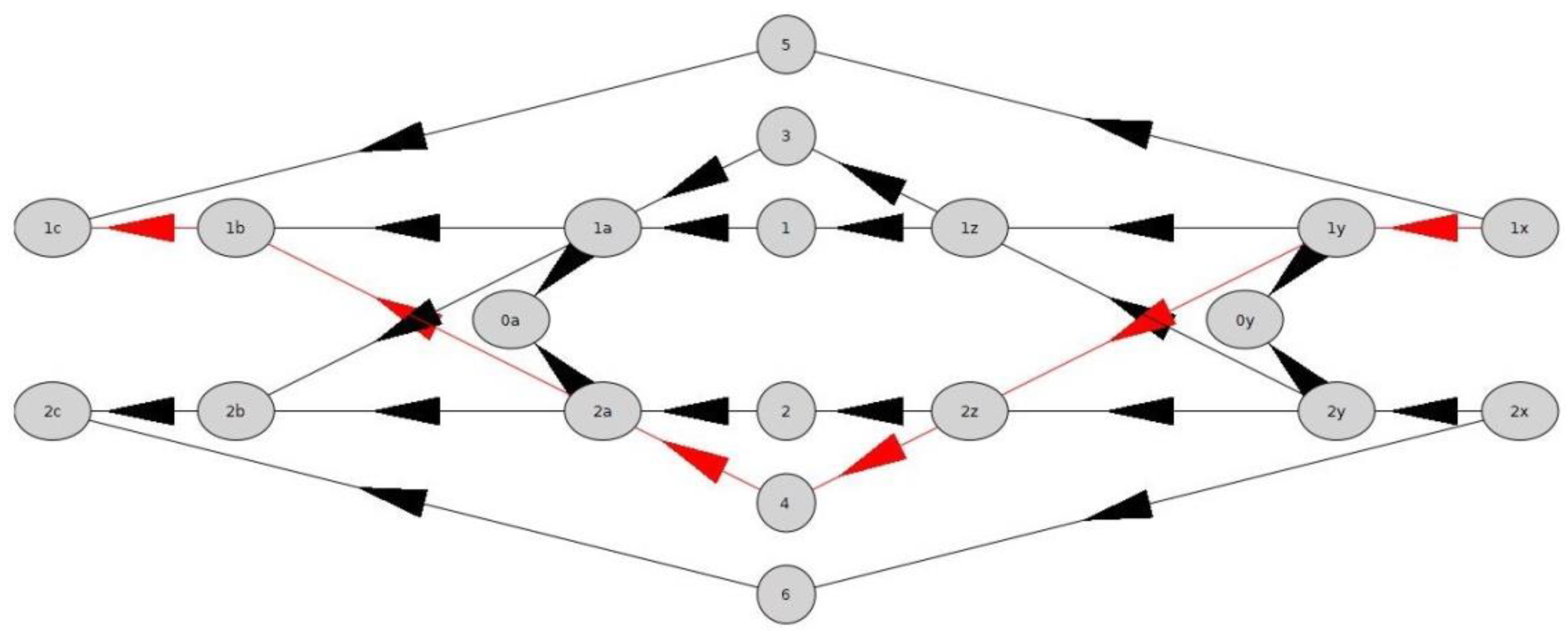
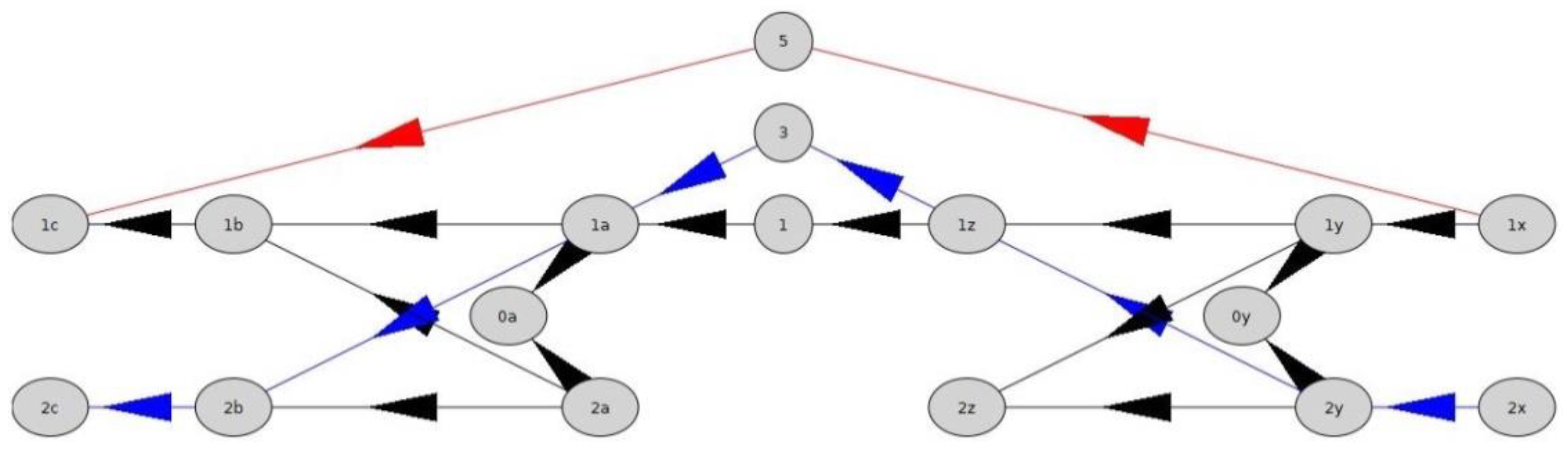
2.4. The Inspiration

Finally, a successful attempt was found, mixing both previous attempts. The first attempt only lacks recognizing whether the two routes are disjoint or not. Then, a possible solution is (Figure 13):
  • The two directed arcs, (1y,2z) and (2y,1z), are not split;
  • A new virtual end vertex, 0y, is included;
  • Two new virtual directed arcs, (1y,0y) and (2y,0y), are added to the graph.
This way, no new routes are added, as (1y,0y) and (2y,0y) take to nowhere but to 0y; and the membership of 0y to the two routes allow to decide whether they intersect at the crossing or not.
This approach can be applied to all the “special” turnouts and requires no changes in Estaciones code.

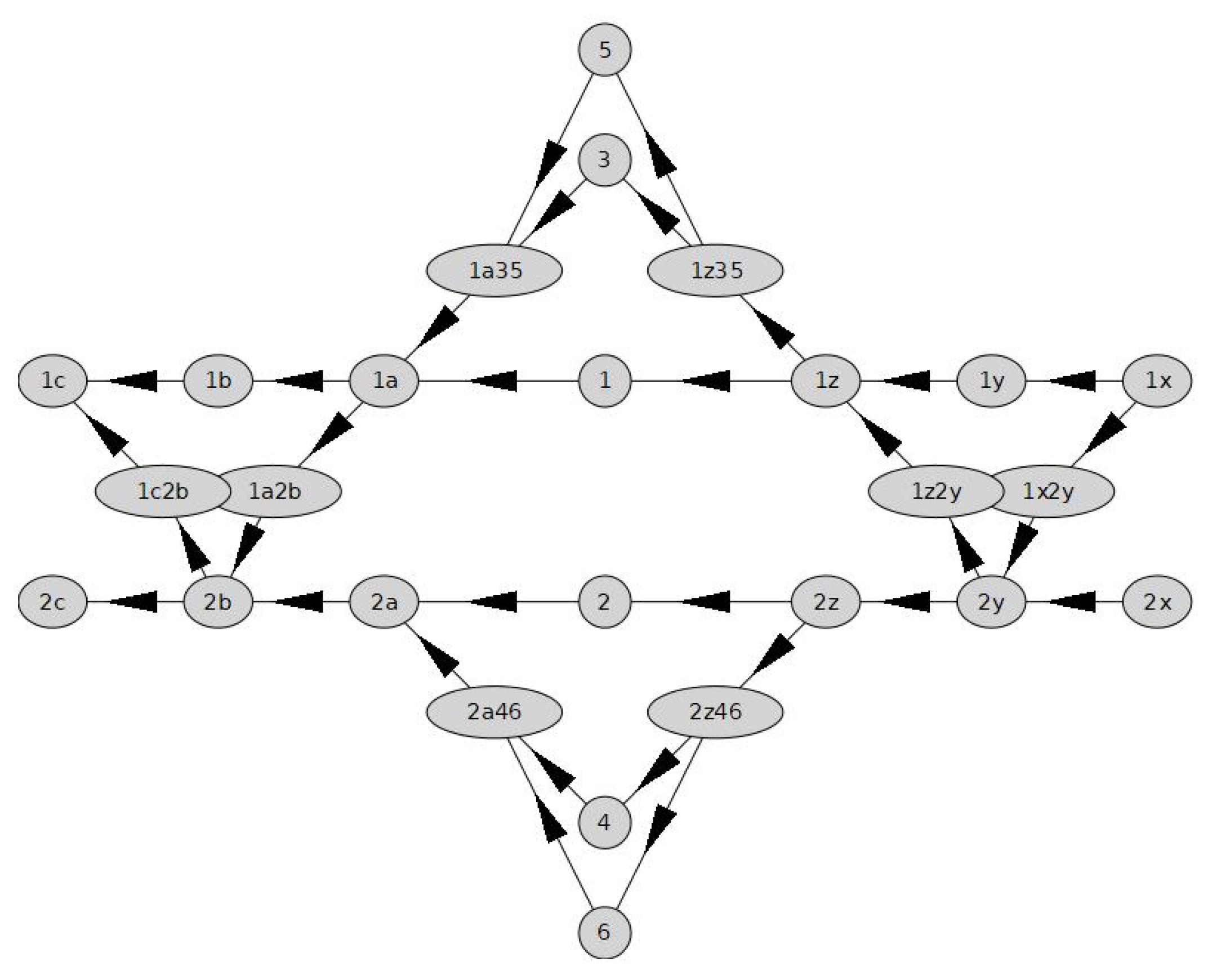
2.5. An Independent Improvement to Estaciones Package

In the Estaciones package, the procedure TotalNumberTrailsExceptThrough (graph, initial1,final1, initial2,final2,list) counted the number of directed trails from initial1 to final1 that are disjoint with the shortest path from initial2 to final2. This number was proposed as a flexibility index for the track layout. (A directed graph is considered. For the sake of brevity we shall write “path” and “trail” meaning “directed path” and “directed trail”, respectively. Directed paths are distinguished from directed trails in this paper because the topology of some railway facilities like reversing loops and reversing triangles could require a train to pass twice through the same vertex.)
However, the trails disjoint with the shortest path were considered even if there was no possible path from initial2 to final2. Therefore, this procedure was changed as it seems more accurate not to consider the existence of an alternative trail to an inexistent one. The new procedure is:
TotalNumberTrailsExceptThrough:=proc(graph,initial1,final1,
                   initial2,final2,list)
   local I,num;
     num:=0;
     for i in list do
       num:=num +
       NumberTrailsExceptThrough(graph,initial2,final2,
          [op({i,op(ShortestPathThrough(G,initial1,
          final1,i))})],list,0);
     end do;
   end proc:
(the line before the end do; is the new one). This code is cryptic for a reader that does not use Maple; however, it is included only to clarify the changes made in the package. The use of the package will be duly commented.
Therefore, the flexibility index proposed in [16] that used this procedure is affected by this change.
The new package is denoted Estaciones2, and is freely available from the author.

3. Results

With the trick described in Section 2.4, the track layout of any overtaking stations on double-track lines can be analysed.
From the point of view of a mathematician, the track layout diagram of Figure 6 lacks symmetry and route compatibility does not seem trivial to visually check. Would it be possible to conceive something similar, but symmetric and simpler; for instance, using scissors crossings? The answer is yes (Figure 14).
The Maple 2022 code necessary to analyse a new track layout proposal with the Estaciones2 package is included below.
It is advisable to begin restarting the session before loading the built-in GraphTheory package and the package described in this article:
restart;
with(GraphTheory):
read(`C:/…/Estaciones2.mpl`):
The names of the vertices of the digraph and their connectivity can be introduced afterwards:
G := Digraph([“5”,”3”,”1c”,”1b”,”1a”,”1”,”1z”,”1y”,”1x”,”0a”,”0y”,
    “2c”,”2b”,”2a”,”2”,”2z”,”2y”,”2x”,”4”,”6”],
    {[“1x”,”5”], [“1x”,”1y”],[“1y”,”1z”],[“1y”,”0y”],
     [“1y”,”2z”],[“1z”,”1”], [“1z”,”3”], [“1”,”1a”],
     [“3”,”1a”], [“1a”,”1b”],[“1a”,”0a”],[“1a”,”2b”],
     [“1b”,”1c”],[“5”,”1c”], [“2x”,”6”], [“2x”,”2y”],
     [“2y”,”2z”],[“2y”,”0y”],[“2y”,”1z”],[“2z”,”4”],
     [“2z”,”2”], [“2”,”2a”], [“4”,”2a”], [“2a”,”2b”],
     [“2a”,”0a”],[“2a”,”1b”],[“2b”,”2c”],[“6”,”2c”]}):
(In Maple := is used to assign values to variables. Semicolons and colons are statement separators; and the result is not displayed if a colon is used).
It is a good idea to allocate the vertices (it has to be done manually), so that the plot of the digraph resembles the railway station; for instance:
vp := [[0.4,1.2],[0.4,1],[−1.2,0.8],[−0.8,0.8],[0,0.8],[0.4,0.8],
     [0.8,0.8],[1.6,0.8],[2,0.8],[−0.2,0.6],[1.4,0.6],
     [−1.2,0.4],[−0.8,0.4],[0,0.4],[0.4,0.4],[0.8,0.4],
     [1.6,0.4], [2,0.4],[0.4,0.2], [0.4,0]]:
and the line of code afterwards produces the plot of Figure 15.
SetVertexPositions(G,vp):
The accessibility is not perfect in this case (one track of the six tracks of the station is not accessible from each throat); for instance, section 6 cannot be reached from section 1x:
AreReachableList(G,”1x”,[“1”,”2”,”3”,”4”,”5”,”6”]);
              “1”, true
              “2”, true
              “3”, true
              “4”, true
              “5”, true
              “6”, false
(observe that the inputs are left-aligned while the outputs are centered, as is usual in Maple).
In addition, it is straightforward to obtain, for instance, a shortest path (counting the number of vertices) from 1x to 1c through 4 and to plot it in red colour (Figure 16):
ww:=ShortestPathThrough(G,”1x”,”1c”,”4”);
     ww := [“1x”, “1y”, “2z”, “4”, “2a”, “1b”, “1c”]
HighlightTrail(G,ww,red);
DrawGraph(G);
This new track layout proposed has the same advantage as the one of Figure 6: even in a degraded scenario where a main track of the station and all sidings at that side are unavailable, still two disjoint routes from one throat to the other (for instance, from 1x to 1c and from 2x to 2c) can be found:
jj:=ShortestPathThrough(G,”1x”,”1c”,”5”);
HighlightTrail(G,jj,red);
GD1:=DeleteVertices(G,jj);
GD2:=DeleteVertices(GD1,[“2”,”4”,”6”]);
gg:=ShortestPath(GD2,”2x”,”2c”);
HighlightTrail(G,gg,blue);
DrawGraph(DeleteVertices(G,[“2”,”4”,”6”]));
(see Figure 17). Let us underline that such a degraded scenario is not so strange. In the standard track layout of Figure 4 it can happen if there is a serious problem with one of the turnouts on the main track or if there is a partial problem with the electricity supply (the even and odd tracks usually have separated energy supplies [28]).
We can also check the (corrected) flexibility index proposed in Section 2.5 for this new alternative track layout:
TotalNumberTrailsExceptThrough(G,”2x”,”2c”,”1x”,”1c”,
               [“1”,”3”,”5”,”2”,”4”,”6”]);
               21
that is bigger than the index of the alternative layout proposed in [16], itself much bigger than the index of the standard track layout (see Section 4). An analogous result would be obtained substituting the scissors crossovers by two crossovers at the same position on each side of the station.

4. Discussion

This article is a natural continuation of [16], and shows how to address all kinds of turnouts; therefore, allowing now to treat all kinds of overtaking stations on double-track lines. Note that [16] was inspired by [14], where the objective was to find compatible routes in the railway interlocking systems of overtaking stations. In all of these works, the stations can have any topology.
Apart from these articles, we have only found a very close article [29], where a terminus station (instead of an overtaking station) is analysed using graph theory (with a matrix-style notation). The topology is fixed in this case (three tracks).
The new extension allows proposing a track layout for overtaking stations on double-track lines with advantages over the standard track layout and even over the one proposed in [16]. In the first line of Table 1, the flexibility index proposed in Section 2.5 is computed for the first and third track layouts using:
TotalNumberTrailsExceptThrough(G,”2x”,”2c”,”1x”,”1c”,
               [“1”,”3”,”5”,”2”,”4”,”6”]);
and for the second track layout using:
TotalNumberTrailsExceptThrough(G,”2w”,”2d”,”1w”,”1d”,
               [“1”,”3”,”5”,”2”,”4”,”6”]);
This procedure calculates how many trails are there from the 1st vertex to the 2nd one, excluding the shortest path between the 3rd and 4th vertices, that pass through one of the vertices in the list introduced as last input.
In order to analyse in depth the three data obtained corresponding to the three layouts analysed, it is possible to detail all the cases one by one with:
list00:=[“1”,”3”,”5”,”2”,”4”,”6”]:
for i in list00 do
   print(NumberTrailsExceptThrough(G,”1x”,”1c”,
       [op({i,op(ShortestPathThrough(G,”2x”,”2c”,i))})],
       list00,1));
end do;
(what was used to fill the rows 2nd to 7th in Table 1, substituting the x by w and the c by d when computing the case of the second track layout).
Different branches of computer science have direct applications in railway engineering [30,31,32]. Graph theory is the underlying theory in many cases and CAS is often the digital tool chosen.
We believe that we present in this article a very useful and flexible tool for the track layout design of overtaking stations of any topology (it can handle all types of turnouts).
Moreover, it was successfully used to propose an alternative advantageous track layout for overtaking stations on double-track lines with two sidings on each side of the main tracks. We claim that the track layout proposal of Figure 14 has advantages over the classic one (Figure 4) because there are more disjoint trails in the proposal (see Table 1); what is key in the case of operating the station in a degraded scenario. The computations were carried out using the package introduced in this article.
We know of no station with the track layout proposed in Figure 14 (let us remember that the scissors crossovers can be substituted by two crossovers at the same position on each side of the station). For instance, in [4], a detail of all the stations in the world’s high-speed lines in 2015 can be found. Scissors crossings are relatively frequent in Japanese high-speed lines between the two main tracks; however, they are not used exactly as proposed here. In the Spanish high-speed stations, they are used in the middle of the tracks of some terminus stations to allocate one short train after another one; allowing the one in the back to leave the station through the adjacent track. In France, they can be found in one of the stations of the Rhin-Rhône high-speed line.

Supplementary Materials

The following supporting information can be downloaded at: https://www.mdpi.com/article/10.3390/a15100368/s1. The Maple package Estaciones2 is freely available from the author.

Funding

This research was partially supported by the research projects PGC2018-096509-B-I00 and PID2021-122905NB-C21 (Government of Spain).

Data Availability Statement

Future users can download the data through Supplementary Materials.

Conflicts of Interest

The author declares no conflict of interest.

References

  1. Losada, M. Curso de Ferrocarriles: Explotación Técnica; E.T.S.I. Caminos: Madrid, Spain, 1991. [Google Scholar]
  2. Westwood, J. (Ed.) Trains; Octopus Books Ltd.: London, UK, 1979. [Google Scholar]
  3. Yi, S. Principles of Railway Location and Design; Academic Press: London, UK, 2018. [Google Scholar]
  4. Martín Cañizares, M.P. Contribución al Diseño Eficiente de la Configuración en Planta de Líneas de Alta Velocidad. Ph.D. Thesis, Universitat Politécnica de Catalunya, Barcelona, Spain, 2015. Available online: https://vlibre.org/619/01.pdf (accessed on 2 October 2022).
  5. Roanes-Lozano, E.; González-Franco, I.; Hernando, A.; García-Álvarez, A.; Mesa, L.E. Optimal Route Finding and Rolling-Stock Selection for the Spanish Railways. Comput. Sci. Eng. 2012, 14, 82–89. [Google Scholar] [CrossRef]
  6. Fundación de los Ferrocarriles Españoles. Available online: https://www.ffe.es/principal_en.asp (accessed on 2 October 2022).
  7. Calvera, P.J.; Casas Rodríguez, J.C. Las 250 Estaciones Españolas Con Ancho Ibérico Más Importantes; Gestión Ferroviaria S. L.: Barcelona, Spain, 2019. [Google Scholar]
  8. van Hulzen, J.A.; Calmet, J. Computer algebra systems. In Computer Algebra. Symbolic and Algebraic Manipulation; Buchberger, B., Collins, G.E., Loos, R., Eds.; Springer: Vienna, Austria, 1982; pp. 221–243. [Google Scholar]
  9. Wester, M.J. Computer Algebra Systems: A Practical Guide; Wiley: Chichester, UK, 1999. [Google Scholar]
  10. Bernardin, L.; Chin, P.; DeMarco, P.; Geddes, K.O.; Hare, D.E.G.; Heal, K.; Labahn, G.M.; May, J.P.; McCarron, J.; Monagan, M.B.; et al. Maple Programming Guide; Maplesoft, Waterloo Maple Inc.: Waterloo, ON, Canada, 2011; Available online: https://www.maplesoft.com/view.aspx?sf=103828/337201/programmingguide.pdf (accessed on 2 October 2022).
  11. Corless, R. Essential Maple. An Introduction for Scientific Programmers; Springer: New York, NY, USA, 1995. [Google Scholar]
  12. Heck, A. Introduction to Maple; Springer: New York, NY, USA, 2003. [Google Scholar]
  13. Maplesoft. Maple User Manual; Maplesoft, Waterloo Maple Inc.: Waterloo, ON, Canada, 2020; Available online: https://www.maplesoft.com/documentation_center/maple2020/UserManual.pdf (accessed on 2 October 2022).
  14. Roanes-Lozano, E. Looking for compatible routes in the railway interlocking system of an overtaking station using a computer algebra system. In Computer Algebra in Scientific Computing. CASC 2020; Boulier, F., England, M., Sadykov, T.M., Vorozhtsov, Eds.; Lecture Notes in Computer Science; Springer International Publishing Switzerland: Cham, Switzerland, 2020; Volume 12291, pp. 528–542. [Google Scholar] [CrossRef]
  15. Kavithaa, T.; Liebchenb, C.; Mehlhornc, K.; Michaild, D.; Rizzie, R.; Ueckerdtf, T.; Zweig, K.A. Cycle bases in graphs characterization, algorithms, complexity, and applications. Comp. Sci. Rev. 2009, 3, 199–243. [Google Scholar] [CrossRef] [Green Version]
  16. Roanes-Lozano, E.; Galán-García, J.L.; Aguilera-Venegas, G. A computer approach to overtaking station track layout diagram design using graphs. An alternative track diagram proposal for these stations. J. Comp. Appl. Math. 2021, 391, 113455. [Google Scholar] [CrossRef]
  17. Ebrahimi, M.; Ghebleh, M.; Javadi, M.; Monagan, M.; Wittkopf, A. A Graph Theory Package for Maple, Part II: Graph Coloring, Graph Drawing, Support Tools, and Networks. In Proceedings of the 2006 Maple Conference, Waterloo, ON, Canada, 23–26 July 2006; Maplesoft: Waterloo, ON, Canada, 2006; pp. 99–112. [Google Scholar]
  18. Farr, J.; Khatarinejad Fard, M.; Khodadad, S.; Monagan, M. A Graph Theory Package for Maple. In Proceedings of the 2005 Maple Conference, Waterloo, ON, Canada, 17–20 July 2005; Maplesoft: Waterloo, ON, Canada, 2005; pp. 260–271. [Google Scholar]
  19. Adif. Available online: http://www.adif.es/ (accessed on 2 October 2022).
  20. Estudio Informativo del Nuevo Complejo Ferroviario de la Estación de Madrid-Chamartín. Ministerio de Transportes, Movilidad y Agenda Urbana. Available online: https://www.mitma.gob.es/ferrocarriles/estudios-en-tramite/estudios-y-proyectos-en-tramite/chamartin (accessed on 2 October 2022).
  21. Adjudicada la Modificación de Las Instalaciones de Seguridad, ERTMS, Comunicaciones y Energía de Madrid-Chamartín. Boletín Vía Libre 30 July 2021. Available online: https://www.vialibre-ffe.com/noticias.asp?not=33047&cs=infr (accessed on 2 October 2022).
  22. Briginshaw, D. Adif Awards Madrid Track Remodelling Planning Contract. Int. Railw. J. 5 February 2020. Available online: https://www.railjournal.com/passenger/commuter-rail/adif-awards-madrid-track-remodelling-planning-contract/ (accessed on 2 October 2022).
  23. Comienzan las Obras del Nuevo Esquema de Vías de Estacionamiento de Ancho Convencional de Barcelona Sants. Boletín Vía Libre 25 May 2020. Available online: https://www.vialibre-ffe.com/noticias.asp?not=29524 (accessed on 2 October 2022).
  24. Segunda Fase del Nuevo Esquema de Vías de Estacionamiento de Ancho Convencional de Barcelona-Sants. Boletín Vía Libre 7 September 2020. Available online: https://www.vialibre.org/noticias.asp?not=30025 (accessed on 2 October 2022).
  25. Licitada la Ampliación de las Vías de Estacionamiento de Trenes AVE en Sevilla Santa Justa y Majarabique. Boletín Vía Libre 25 May 2020. Available online: https://www.vialibre.org/noticias.asp?not=29527 (accessed on 2 October 2022).
  26. Inaugurados la Nueva Estación y el Nuevo Haz de Vías de Canfranc, en Huesca. Boletín Vía Libre 16 April 2021. Available online: https://www.vialibre-ffe.com/noticias.asp?not=31308&cs=infr (accessed on 2 October 2022).
  27. Licitadas las Obras Para la Sustitución de Desvíos Para Mejorar la Circulación Entre Granada y Almería. Boletín Vía Libre 11 March 2021. Available online: https://www.vialibre-ffe.com/noticias.asp?not=31123&cs=infr (accessed on 2 October 2022).
  28. Roanes-Lozano, E.; González-Martín, R.; Montero, J. A Knowledge-Based System for DC Railway Electrification Verification. Math. Comp. Sci. 2019, 13, 449–457. [Google Scholar] [CrossRef]
  29. Powell, S.; Wong, H.Y. A deterministic approach to evaluating transport infrastructure at a terminus. Trans. Res. A 2000, 34, 287–302. [Google Scholar] [CrossRef]
  30. Falcón, R.; Barrena, E.; Canca, D.; Laporte, G. Counting and enumerating feasible rotating schedules by means of Gröbner bases. Math. Comput. Simul. 2016, 125, 139–151. [Google Scholar] [CrossRef]
  31. Laporte, G.; Mesa, J.A.; Ortega, F.A.; Pozo, M.A. Locating a metro line in a historical city centre: Application to Sevilla. J. Oper. Res. Soc. 2009, 60, 1462–1466. [Google Scholar] [CrossRef]
  32. Xiangxian, C.; Yulin, H.; Huang, H. A component-based topology model for railway interlocking systems. Math. Comput. Simul. 2011, 81, 1892–1900. [Google Scholar] [CrossRef]
Figure 1. A turnout with its switch in the “direct track” position.
Algorithms 15 00368 g001
Figure 2. A light signal in a main station.
Algorithms 15 00368 g002
Figure 3. Track layout diagram of a small overtaking station on a double-track line. It has one siding on each of the sides of the main line and two crossovers at the two throats of the station. For example, in the Spanish high-speed network, the following stations have exactly this track layout: Bujaraloz, Ballobar, L’Espluga, El Prat (Spanish high-speed line Madrid–Barcelona [4] (p. 62)); Puente Genil (Spanish high-speed line Córdoba–Málaga [4] (p. 66)); Requena-Utiel (Spanish high-speed line Madrid–Valencia [4] (p. 68)).
Algorithms 15 00368 g003
Figure 4. Track layout diagram of another small overtaking station on a double-track line (it has two sidings on each of the sides of the main line and two crossovers at the two throats of the station). For example, the station Cuenca Fernando Zobel (on the Spanish high-speed line Madrid–Valencia) has exactly this track layout [4] (p. 68). Fukushima station (on the Japanese Tohoku Shinkansen line) is very close to this one; the only difference is that it has only one crossover at one of the throats of the station [4] (p. 36). Similarly, Camp de Tarragona station (on the Spanish high-speed line Madrid–Barcelona [4] (p. 62)) has three sidings on each of the sides of the main line; however, it has crossovers only on one throat of the station.
Algorithms 15 00368 g004
Figure 5. An alternative track layout diagram for a small overtaking station on a double-track line.
Algorithms 15 00368 g005
Figure 6. A better alternative track layout diagram for a small overtaking station on a double-track line.
Algorithms 15 00368 g006
Figure 7. A double-slip turnout.
Algorithms 15 00368 g007
Figure 8. A scissors crossover. It consists of four turnouts and a crossing.
Algorithms 15 00368 g008
Figure 9. The track layout diagram of Figure 4 divided into sections. Considering vertices 1c2b, 1a2b, 1z2y, and 1x2y is not strictly necessary; however, they were considered in [16] in order to closely resemble the connectivity of the turnouts.
Algorithms 15 00368 g009
Figure 10. Graphical representation in Maple of the digraph corresponding to the connectivity of the track layout diagram of Figure 9 (the direction considered is from right to left). The coordinates of the vertices of the digraph were manually introduced in order for the plot of the graph to resemble the shape of the railway station.
Algorithms 15 00368 g010
Figure 11. Graphical representation of the first attempt to codify a scissors crossing.
Algorithms 15 00368 g011
Figure 12. Graphical representation of the second attempt to codify a scissors crossing.
Algorithms 15 00368 g012
Figure 13. Graphical representation of a successful attempt to codify a scissors crossing.
Algorithms 15 00368 g013
Figure 14. The new track layout diagram proposal.
Algorithms 15 00368 g014
Figure 15. Plot of the digraph associated to the track layout diagram of Figure 13.
Algorithms 15 00368 g015
Figure 16. A shortest path from 1x to 1c through 4.
Algorithms 15 00368 g016
Figure 17. Two disjoint routes found in a degraded scenario.
Algorithms 15 00368 g017
Table 1. Comparison of alternative trails in the different track layouts. The acronym “t.s.p.t.” means here “the shortest path through”.
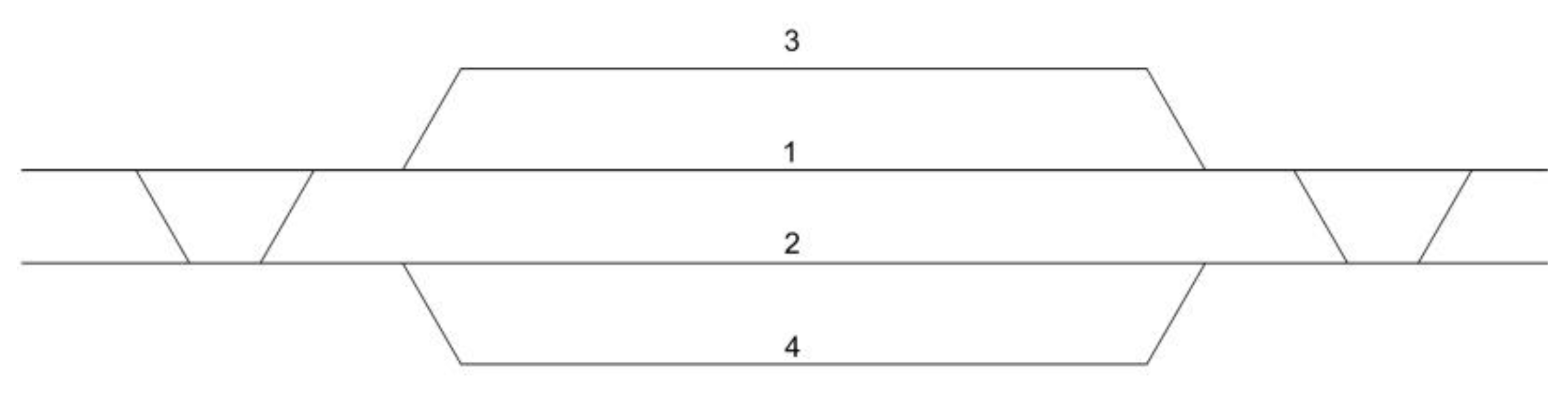
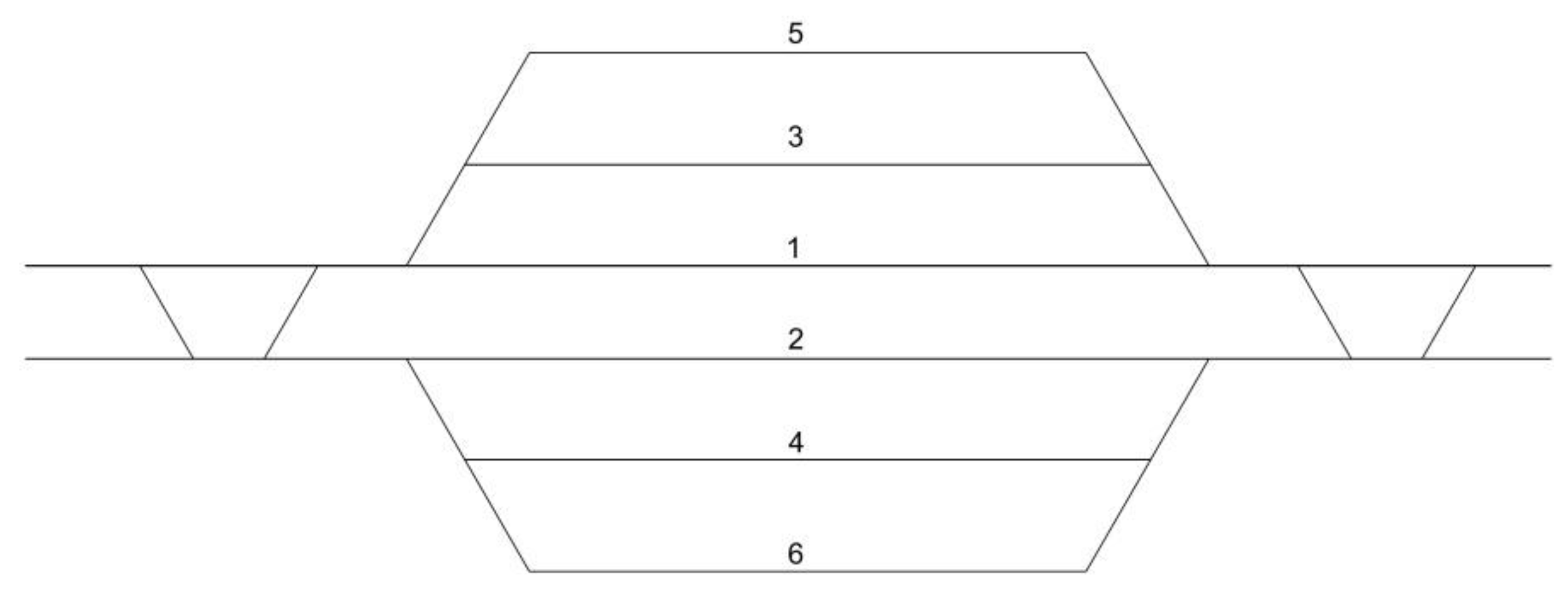
Standard 2 Sidings (Each Side) Track Layout (Figure 4)Alternative 2 Sidings (Each Side) Track Layout from [16] (Figure 6)New Alternative 2 Sidings (Each Side) Layout (Figure 14)
Flexibility index (sum of the amounts below)91721
Disjoint trails with t.s.p.t. section 1013
Disjoint trails with t.s.p.t. section 2013
Disjoint trails with t.s.p.t. section 3044
Disjoint trails with t.s.p.t. section 4333
Disjoint trails with t.s.p.t. section 5333
Disjoint trails with t.s.p.t. section 6355
Publisher’s Note: MDPI stays neutral with regard to jurisdictional claims in published maps and institutional affiliations.

