Article

Structural Analysis and Application of Non-Standard Components Based on Genetic Algorithm

1
School of Electrical and Electronic Engineering, Chongqing Vocational and Technical University of Mechatronics, Chongqing 402760, China
2
School of Mechanical Engineering, Xi’an Jiaotong University, Xi’an 710049, China
*
Author to whom correspondence should be addressed.
Algorithms 2019, 12(8), 169; https://doi.org/10.3390/a12080169
Submission received: 20 July 2019 / Revised: 2 August 2019 / Accepted: 6 August 2019 / Published: 15 August 2019

Abstract

:
Aiming at the problems of low efficiency, heavy quality, and high cost of traditional components, it is necessary to study a design and analysis method of non-standard components. Taking the non-standard parts-turret loading and -unloading device as the carrier, the key parts of the non-standard parts are extracted for structural design and the multi-objective mathematical model and modal theory model are established. The optimization analysis of the key parts is carried out by genetic algorithm. Finally, the optimization results are compared and simulated by ANSYS Workbench. The results show that: in this case, the genetic algorithm optimized data with other data, the overall quality difference is 4.1%. The first six order modal values in the optimized results are in the range of 68 Hz to 130 Hz, which provides a basis for similar research in the future.

1. Introduction

With the development strategy of Made-in-China 2025 and Germany industry 4.0 proposed, and the related policies of other countries, the manufacturing industry has reached a bottleneck. We must break through the bottleneck. In the modern manufacturing system, the traditional manufacturing parts can not meet the needs of individual products, which requires us to innovate the traditional parts and propose the production of non-standard parts [1]. In the mechanical processing manufacturing enterprises, a lot of non-standard machine tools and traditional assembly line equipment are involved to improve the automation of the production line. Thousands of non-standard equipment, the study of non-standard equipment has not been formally incorporated into the real research system [2]. At present, there are two problems in the manufacturing of non-standard parts: one is that the synergy among various plans is not strong enough. The design process of non-standard components from “0” to “1” is not standard enough [3,4]. Therefore, there is a need to set standards in non-standard machinery, including design standards, manufacturing standards and technical indicators and other factors. Therefore, the study of non-standard components is imminent. Many scholars have also studied this aspect: Li G et al. [5] have carried on the research to the non-standard cam. A non-standard cam design system for automobile panel die based on feature reuse and group assembly technology was developed. The system shows good performance through the design of non-standard cam. Jinghua et al. [6] proposed a mapping extraction and equivalent approximation method for multi-granularity macro models supporting non-standard structure design. The design capability of this method is extended from simple devices in a limited cell library to complex, singular and non-standard structures. Pedrero et al. [7] studied the income of unqualified spur gears by using the non-uniform load model. Based on the minimum elastic potential, the meshing conditions of super-hard cylindrical gears were fitted with typical flat web and flat ribs. Zak [8] introduced an advanced method to guide the non-standard geometry design of cylindrical gears. This method adopts finite element method, considers the actual geometry of the whole gearbox and its parts, and solves the problem of gear modification design. Hedlund [9] proposed a parameterized numerical method to generate discrete helical gear geometry and contact lines by simulating the machining process of non-standard gears, i.e., Hobbling. The method is based on coordinate transformation and a wide range of numerical computation points and their synchronization, allowing deviation from ordinary involute geometry. Based on these methods, In this paper, the loading and unloading non-standard parts of turret chuck are used as carriers, Combined with the actual working conditions, the whole machine is designed, the key parts of turret chuck are designed, the multi-objective mathematical model is established, the algorithm is optimized by genetic algorithm, and finally the simulation is carried out through the optimization results, so as to manufacture and process the object and apply it to the actual production of the factory.

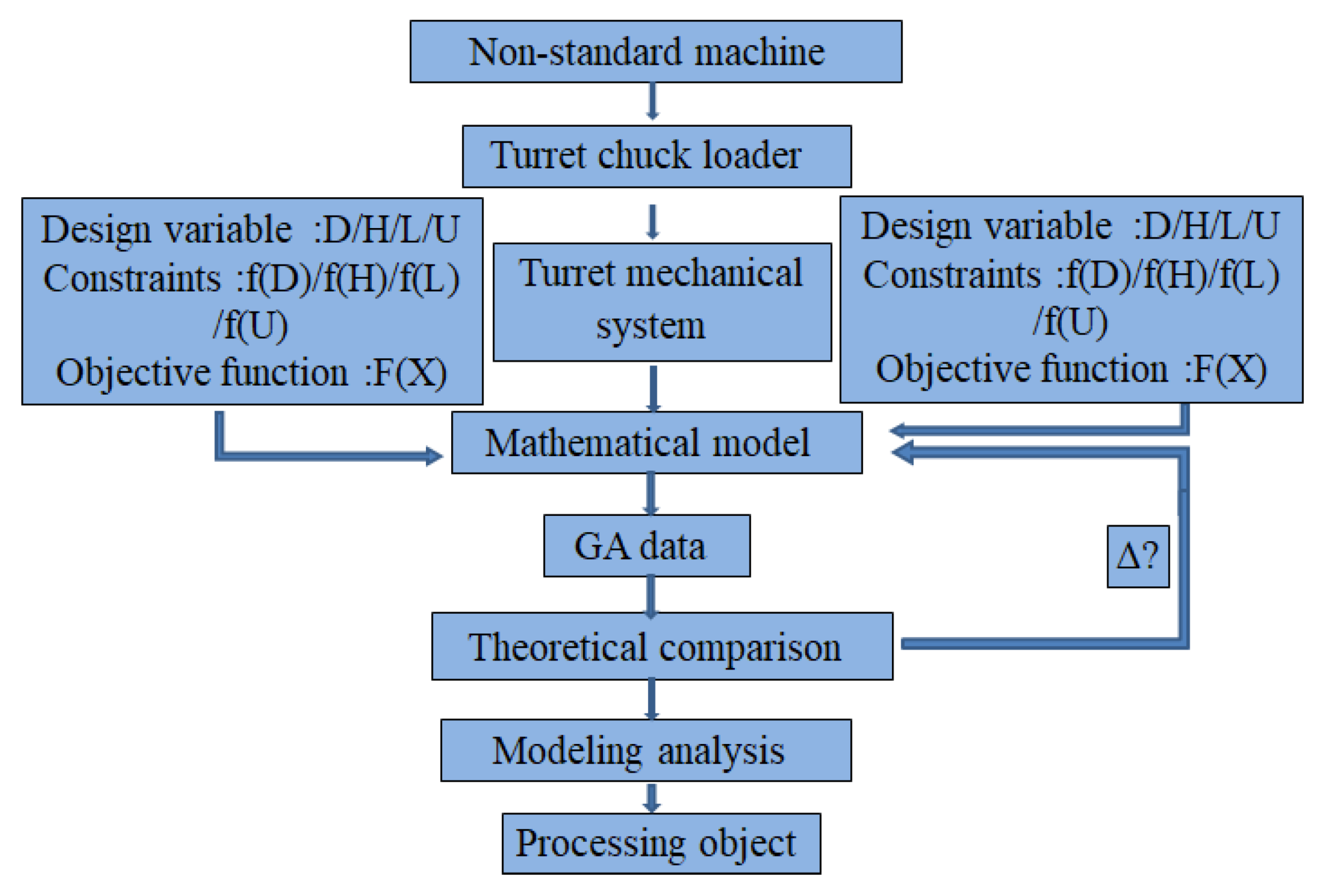
2. Research Framework and Overall Structure Design

2.1. Overall Research Framework

Combined with the actual situation of turret chuck loading and unloading and the research method, the overall research framework flow chart is shown in Figure 1.
According to Figure 1, the general structure of the non-standard part-turret chuck loader is designed, and the key parts-fixed base, rotary base, and two flanges are extracted to design, and the related multi-objective mathematical model is established. The mathematical model parameters include: design variables, constraints, objective function [10]. Secondly, a GA algorithm is used to optimize the established mathematical model, and the optimization results are compared and optimized repeatedly, modeling, and simulation, as well as manufacturing and processing of real objects.

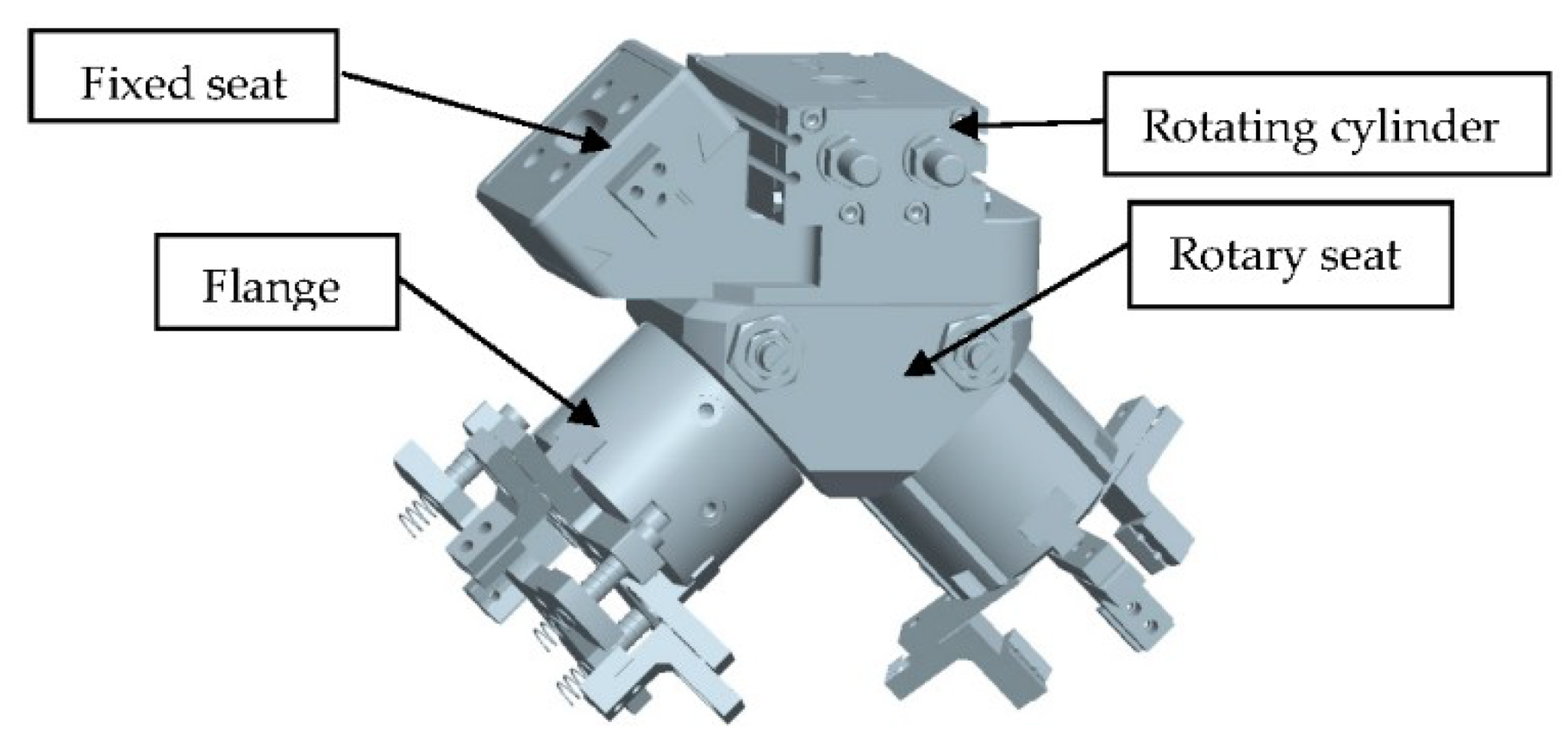
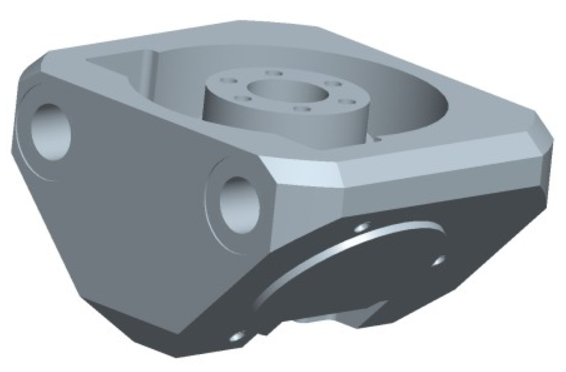
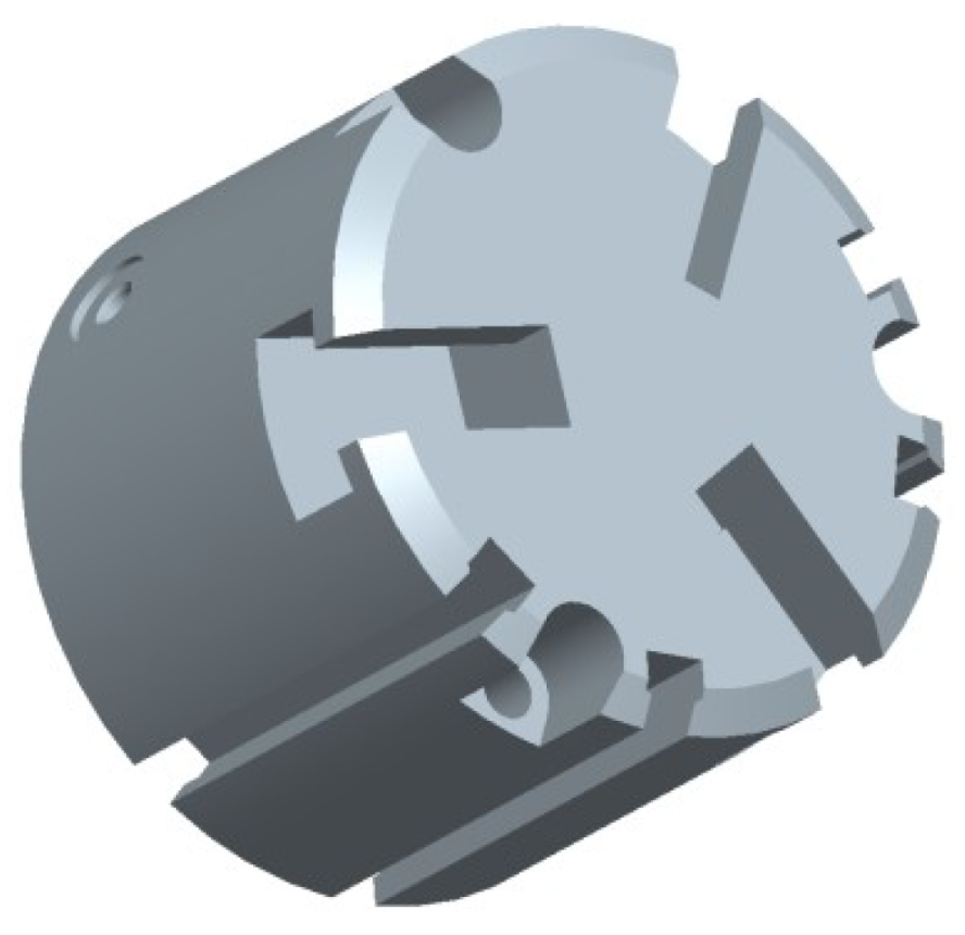
2.2. Overall Structure Design of Non-Standard Components

The design of non-standard parts is mainly used in the working conditions which cannot be completed by standard machines, the purpose is to meet the automation degree of the total generation system is improved on the original basis, so as to reduce labor force, improve production efficiency and economic efficiency [11,12]. The design of non-standard parts is mainly used in the working conditions which be completed by standard machines. According to the actual working conditions, the turret chuck loading and unloading system of non-standard components is extracted, modeled, and analyzed, and its three-dimensional model is shown in Figure 2.
As shown in Figure 2, the turret chuck loading and unloading system is composed of rotating cylinders, fixed seats, rotating seats, and two flanges. An outer coupling end of the rotary seat; outside of the two coupling ends is provided with a material chuck. The rotary seat is provided with a cavity extending inwardly from the coupling end and a flange cover for forming the coupling end. A piston is arranged in the cavity, the piston is fixed with a piston rod passing through the flange cover, and the outer end of the piston rod is provided with at least two or more inclined sliding coupling parts. The center of the flange cover is provided with a center through hole for passing through the piston rod; least two transverse grooves are arranged on the front side of the flange cover. The chuck is a slide block arranged in a transverse slide groove; inner end of the slider is provided with a ramp slide groove. The axial back-and-forth movement of the piston constitutes a clamping movement of the slider in which the slider contracts or expands in the radial direction. The combination of the rotary seat and the flange cover does not require the installation of two clamping cylinders, thereby eliminating unnecessary connecting parts, making the structure of the mechanism more compact, occupying less space, and saving the cost of purchasing the clamping cylinders. In order to meet its basic working requirements, but also to meet the non-standard components in the structure of the cost as little as possible, each processing efficiency higher requirements. The key parts of this non-standard part need to be optimized by algorithm.

3. Theoretical Analysis
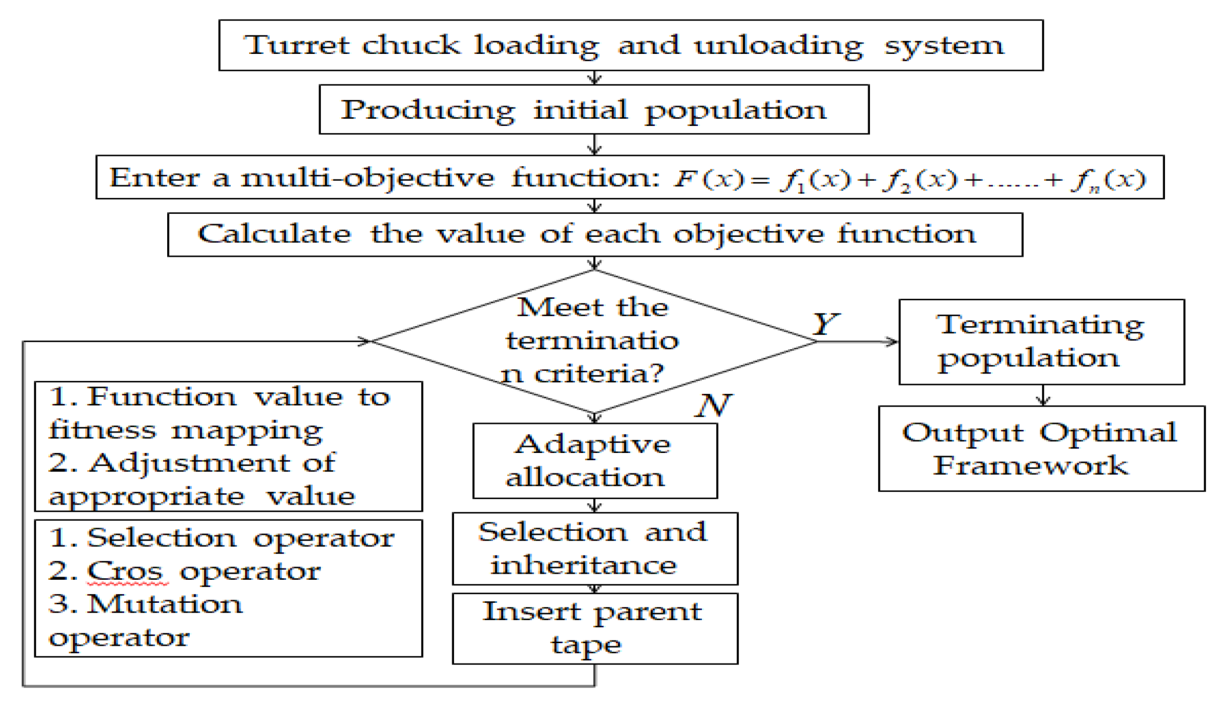
3.1. GA Theory

A GA (genetic algorithm) is based on the parallel search of chromosome clusters, with conjectural rotation operation, exchange operation and mutation operation [13]. For this special combination, the genetic algorithm will be distinguished from other search algorithms [14]. A GA flow chart for that application of the genetic algorithm to the optimization of the feed component is shown in Figure 3.
As can be seen from Figure 3, firstly, multi-objective modeling of turret chuck loading and unloading system is carried out, and the variables corresponding to each objective function are searched to obtain a new set of GA data, and the generated data are corrected at the same time.

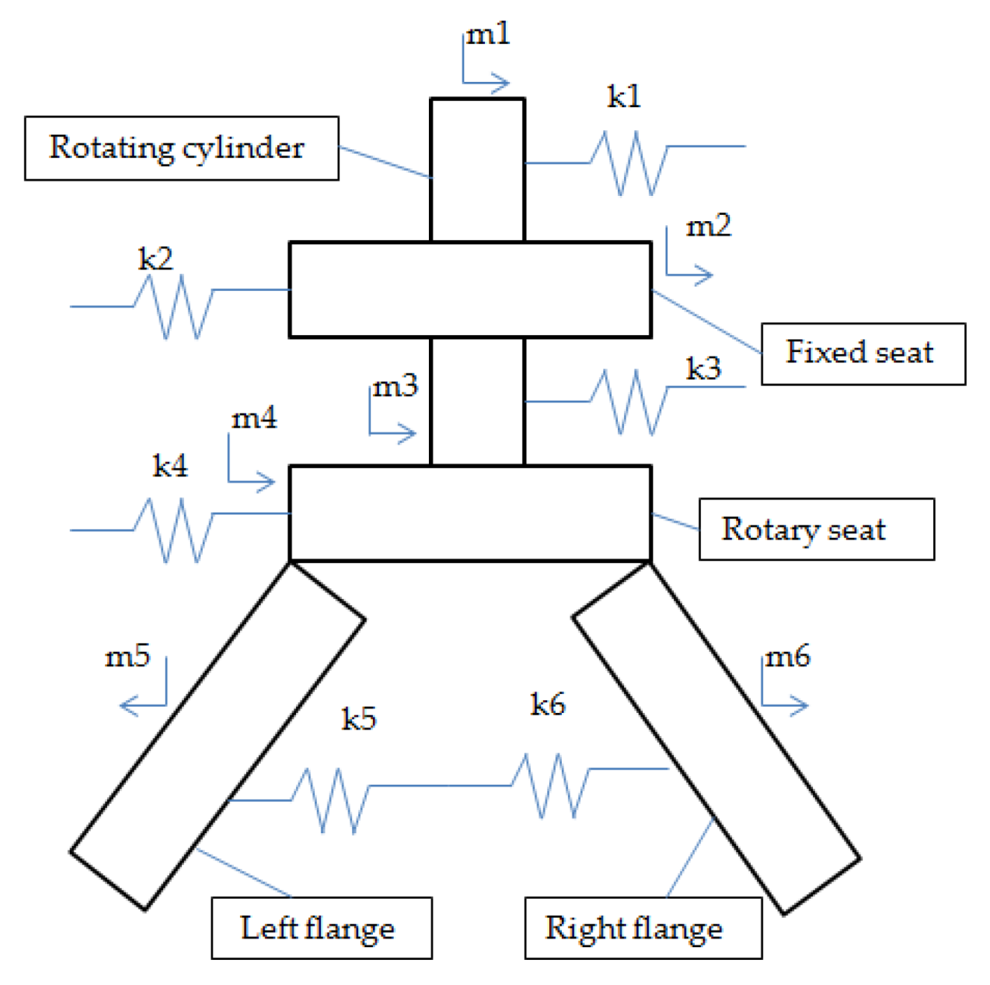
3.2. Establishment of Modal Theory Model

As shown in Figure 2 for the five key parts, simplify the quality system as shown in Figure 4.
According to the simplified mass system diagram shown in Figure 4, the motion equation of the system is established by using Lagrange method, and the expression is as follows:
d d t ( T q ˙ i ) T q i + U q i + D q i = Q i   ( i = 1 , 2 , , n )
where q i and q ˙ i are generalized coordinates and generalized velocities, respectively; T and U are the total kinetic energy and potential energy of the system respectively. D is that energy dissipation function; Q i is the generalized disturbance force [15,16].
As shown in Figure 3, that kinetic energy function of the system is establish as follows:
T = 1 2 ( m 1 x ˙ 1 2 + m 2 x ˙ 2 2 + m 3 x ˙ 3 2 + m 4 x ˙ 4 2 + m 5 x ˙ 5 2 + m 6 x ˙ 6 2 )
The potential energy function is:
U = 1 2 [ k 1 x 1 2 + k 2 ( x 2 x 1 ) 2 + k 3 ( x 3 x 2 ) 2 + k 4 ( x 4 x 3 ) 2 + k 5 ( x 5 x 4 ) 2 + k 6 ( x 6 x 5 ) 2 ]
The energy dissipation function of the system is:
D = 1 2 [ c 1 x ˙ 1 2 + c 2 ( x ˙ 2 x ˙ 1 ) 2 + c 3 ( x ˙ 3 x ˙ 2 ) 2 + c 4 ( x ˙ 4 x ˙ 3 ) 2 + c 5 ( x ˙ 5 x ˙ 4 ) 2 + c 6 ( x ˙ 6 x ˙ 5 ) 2 ]
To this end, the partial derivatives of the functions (2), (3), and (4) in the Lagrange equation and the differential equations of motion of the mechanical system of the turret chuck loader can be obtained by introducing m 1 , m 2 , m 3 , m 4 , m 5 , m 6 in Figure 3, expressed in matrices as:
[ m ] { x ¨ } + [ c ] { x ˙ 1 } + [ k ] { x } = { P }
where { x } { x ˙ } { x ¨ } { P } [ m ] [ c ] and [ k ] denote displacement array, velocity array, acceleration array, interference force array, mass matrix, damping matrix and stiffness matrix, respectively.
When there is no damping, its function (5) is expressed as:
[ m ] { x ¨ } + [ k ] { x } = { 0 }
Let the solution of function (6) be:
{ x } = { A } e i w n t
Of which:
{ A } = { A 1 A 2 A n } , { x } = { x 1 x 2 x n }
The first derivative and the second derivative of the Equation (7) are obtained, respectively, and the equation of the main vibration mode obtained by introducing the Equation (6) into the equation is as follows:
( [ k ] ω n 2 [ m ] ) { A } = { 0 }
Obviously, for { A } to have a non-zero solution, the coefficient determinant in Equation (8) must be zero, i.e., the frequency equation:
det ( [ k ] ω n 2 [ m ] ) = | k 11 m 11 ω n 2 k 12 m 12 ω n 2 k 1 n m 1 n ω n 2 k 21 m 21 ω n 2 k 22 m 22 ω n 2 k 2 n m 2 n ω n 2 k n 1 m n 1 ω n 2 k n 2 m n 2 ω n 2 k n n m n n ω n 2 |
The n-th order algebraic equation of ω n 2 is obtained by expanding it:
ω n 2 n + a 1 ω n 2 ( n 1 ) + a 2 ω n 2 ( n 2 ) + + a n 1 ω n 2 + a n = 0
where a 1 , a 2 , , a n is a combination of k i j and m i j .
According to the mechanical system diagram of the grinding head of the high-speed precision roll grinder as shown in Figure 2, for [ m ] and [ k ] in Equation (6), respectively:
[ m 1 0 0 0 0 0 0 m 2 0 0 0 0 0 0 m 3 0 0 0 0 0 0 m 4 0 0 0 0 0 0 m 5 0 0 0 0 0 0 m 6 ]   and   [ k 1 + k 2 k 2 0 0 0 0 k 2 k 2 + k 3 k 3 0 0 0 0 k 3 k 3 + k 4 k 4 0 0 0 0 k 4 k 4 + k 5 k 5 0 0 0 0 k 5 k 5 + k 6 k 6 0 0 0 0 k 6 k 6 ]
[ m ] and [ k ] are brought into the Formula (8) to obtain:
( [ k 1 + k 2 k 2 0 0 0 0 k 2 k 2 + k 3 k 3 0 0 0 0 k 3 k 3 + k 4 k 4 0 0 0 0 k 4 k 4 + k 5 k 5 0 0 0 0 k 5 k 5 + k 6 k 6 0 0 0 0 k 6 k 6 ] ω n 2 [ m 1 0 0 0 0 0 0 m 2 0 0 0 0 0 0 m 3 0 0 0 0 0 0 m 4 0 0 0 0 0 0 m 5 0 0 0 0 0 0 m 6 ] ) { A 1 A 2 A 3 A 4 A 5 A 6 } = { 0 0 0 0 0 0 }
Finally, the 6-order main modes of the grinding head mechanical system of the high-speed precision roll grinder are obtained: { A ( 1 ) } , { A ( 2 ) } , { A ( 3 ) } , { A ( 4 ) } , { A ( 5 ) } , { A ( 6 ) } .

4. Analysis of Optimal Mathematical Model

Although it is possible to model machining directly according to design experience and machining environment, in order to reduce machining cost and maximize machining efficiency, the optimization analysis is carried out before actual machining [17,18]. The key components in the turret chuck loading and unloading system are the design of the rotating seat and two flanges, as shown in Figure 5 and Figure 6, respectively.

4.1. Establishment of Non-Standard Mechanical Mathematical Model

4.1.1. Multi-Objective Mathematical Model of Structural System Optimization

According to the two most important parts of the turret chuck loading and unloading mechanical system: the rotating seat and the flange, the mathematical model is established [17,18]. Contains multi-objective functions, design variables, and constraint functions. According to the actual parameters of the system and the working condition, the optimization design of the mechanical system of the turret chuck can be expressed as follows:
{ [ min M = i = 1 n F i ( m ) = { F 1 ( m ) + F 2 ( m ) + + F n ( m ) } max N = F ( N ) = { F 1 ( N ) F 2 ( N ) F n ( N ) } N = ( n 1 , n 2 , , n n ) g n ( i ) > 0 ; i = D , H , L , D ( N ) > 0 ; H ( N ) > 0 ; L ( N ) > 0 ; U > 0 ;
where: D ;   H ;   L ;   U are design variables; min M ; max N - objective functions, i = 1, 2, …, n; D ( N ) ;   H ( N ) ;   L ( N ) ;   U - constraint functions and equality constraint functions; D ( N ) > 0 ; H ( N ) > 0 ; L ( N ) > 0 ;   U > 0 - the lower limits of the design variables; and m -quality.

4.1.2. Optimization Multi-Objective Function

In the optimization design of mechanical structure system, the change of the size and structure of rotating seat and flange, the change of the size of coupling inclination, the start and stop of the turret chuck loader and some external disturbance factors will lead to the loading and unloading vibration [19]. Under the condition of meeting the requirements of the mechanical structure transmission system of the feeding and unloading machine, the overall minimum volume of the mechanical structure of the system and the transmission efficiency are taken as the multi-objectives to be pursued, so as to reduce the weight, save the material and reduce the cost. The total mass objective function of the mechanism system and the total transmission efficiency are as follows:
min M = i = 1 n F i ( m ) = { F 1 ( m ) + F 2 ( m ) + + F n ( m ) } max N = F ( N ) = { F 1 ( N ) F 2 ( N ) F n ( N ) }
where M is the total mass; N is the total efficiency.

4.1.3. Constraints

1. Torsional strength
According to the torsional strength, the torsional shear stress of turret chuck loader must satisfy τ max = T W t [ τ ] ; Where T is the torque of the turntable, T = 9549 P n ( N m ) ; W t is that modulus of torsional section, W t = π D i 3 16 ( M P a ) .
2. Torsional stiffness
In order to ensure proper operation of the drive system, the deformation of the flange should be limited. The limited deformation condition is stiffness condition, which usually requires the maximum torsion angle per unit length not to exceed the allowable value, namely ϕ = T G I p [ ϕ ] . Where ϕ is the torsion angle per unit length, rad; G is shear modulus, MPa; I p is that polar moment of inertia, m4.
3. Structural dimensions
The constraints determined by the structural size requirements are: d > 0 ;   u > 0 ;   w > 0 . From P = 2 π × n 60 T = 9549 × p n get I p = π D i 3 32 9549 × 5.5 × 16 5000 × π × D i 3 × 10 6 211.1 0 ϕ = M n G I p × 180 π = 32 M n G π D i 3 × 180 π = 9549 × 5.5 × 32 × 180 5000 × π 2 × 80 × D i 3 1 0 .
At that same time, accord to the key structural system diagrams and actual structure of the feeding and unloading machine as shown in Figure 5 and Figure 6, The system is divided into 10 design parameters: the maximum diameter D 1 of the inner hole of the rotary seat, the outer diameter D 2 of the central hole of the rotary seat, the inner diameter D 3 of the central hole of the rotary seat, the outer diameter D 4 of the flange, the inclination U of the rotary seat, the height H 1 of the rotary seat, the height H 2 of the flange, the outer diameter depth H 3 of the central hole of the rotary seat, the length L 1 of the rotary seat and the width L 2 of the rotary seat. Initial values, ranges of variations and assignment parameter codes are listed according to the time and experience, as shown in Table 1.
After all the function expressions are normalized, the data of Table 1 are brought into it, and the multi-objective mathematical model of optimization design of mechanical structure system is obtained, namely:
min M = F ( X ) = i = 1 i = 3 24818.58 × 10 - 6 × [ L 1 × L 2 × H 1 D i 2 4 π H 1 ( L 1 D 2 ) × L 2 ] + D 4 2 4 π H 2
Constraints met: { g 1 ( X ) = 253 × 1 X i 3 1 0 g 2 ( X ) = 0.0766 × 10 6 X i 3 1 0 65 m m X 1 80 m m 35 m m X 2 50 m m 15 m m X 3 35 m m 65 m m X 4 100 m m 0.2 X 5 5 50 m m X 6 80 m m 40 m m X 7 75 m m 17 m m X 8 35 m m 80 m m X 9 120 m m 80 m m X 10 110 m m

4.2. Algorithm Analysis Result

According to the transmission system optimization model of turret chuck loader, combined with genetic toolbox in MATLAB optimization toolbox to optimize the system structure, the final comparison results were verified [20,21]. This is a multi-constrained nonlinear problem, which transforms the function y = fun n (x) language in the objective function m file and uses the MATLAB, the high-tech computing environment for scientific computing, visualization and interactive programming, released by mathworks, USA, genetic toolkit to select @ fun n in the Fitness function, sets the Number of variables to 18. Lower value inputs [65, 35, 15, 65, 0.2, 50, 40, 17, 80, 80]. Upper value inputs [80, 50, 35, 100, 5, 80, 75, 35, 120, 110], sets the Population size to 50, Crossing to 0.8, and Graph to 0.01. The process stops after 50 iterations. The corresponding values of six sets of optimization results are randomly generated as shown in Table 2.
Through the analysis of the optimized data by six algorithms in Table 2, each set of actual value is brought into the objective function for calculation, and finally the GA data value is obtained [78; 40; 20; 70; 1; 61; 52; 22.5; 112; 92] is less than the rest of the optimized values. Based on this, [78; 40; 20; 70; 1; 61; 52; 22.5; 112; 92] This set of data is then analyzed.

5. Simulation and Experimental Analysis

As shown in Table 2, and for that above genetic algorithm comparison results analysis. A set of data optimized by genetic algorithm is selected and modal analysis is carried out according to the previous modal theory model, in order to study whether it satisfies the actual operating conditions.

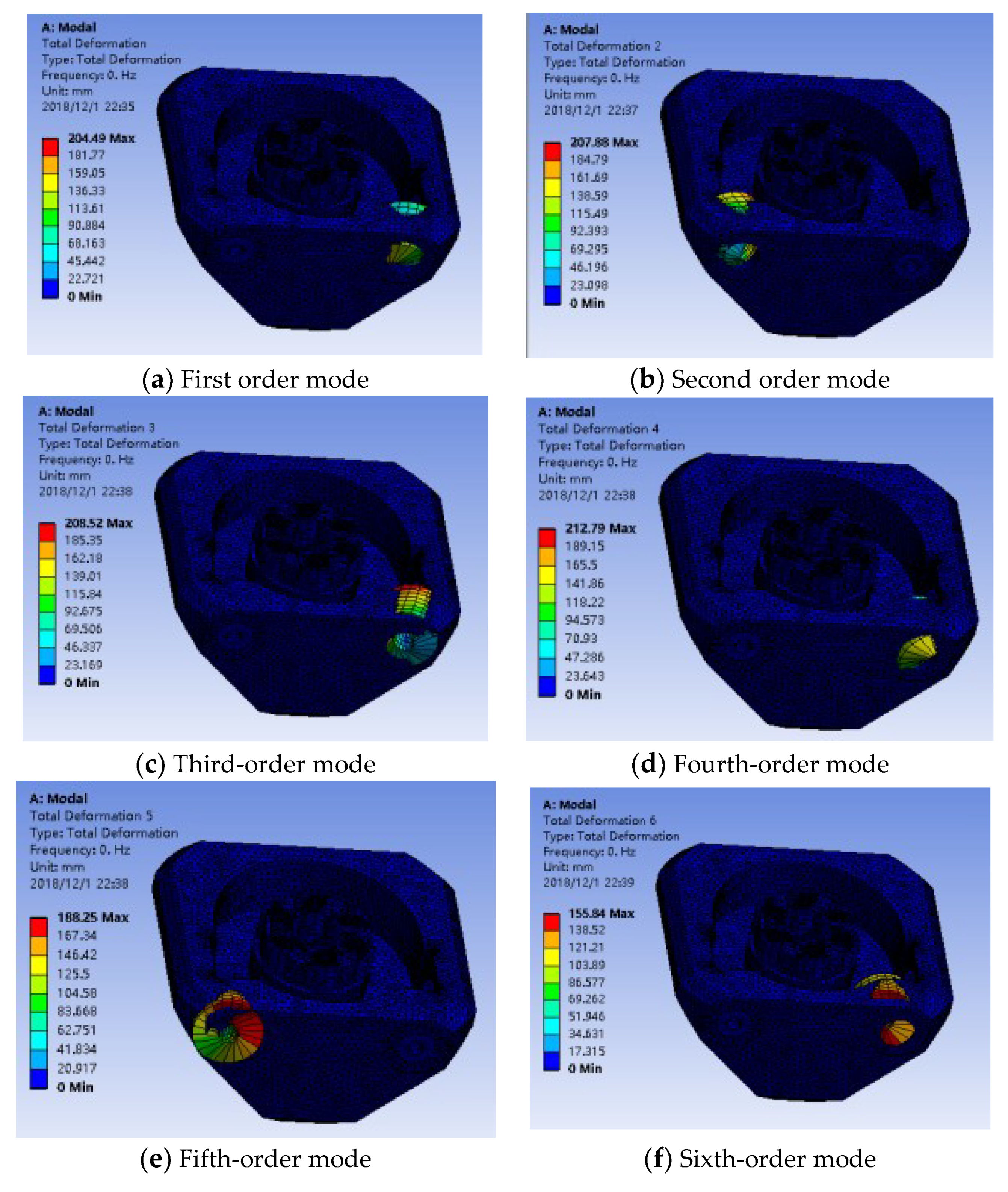
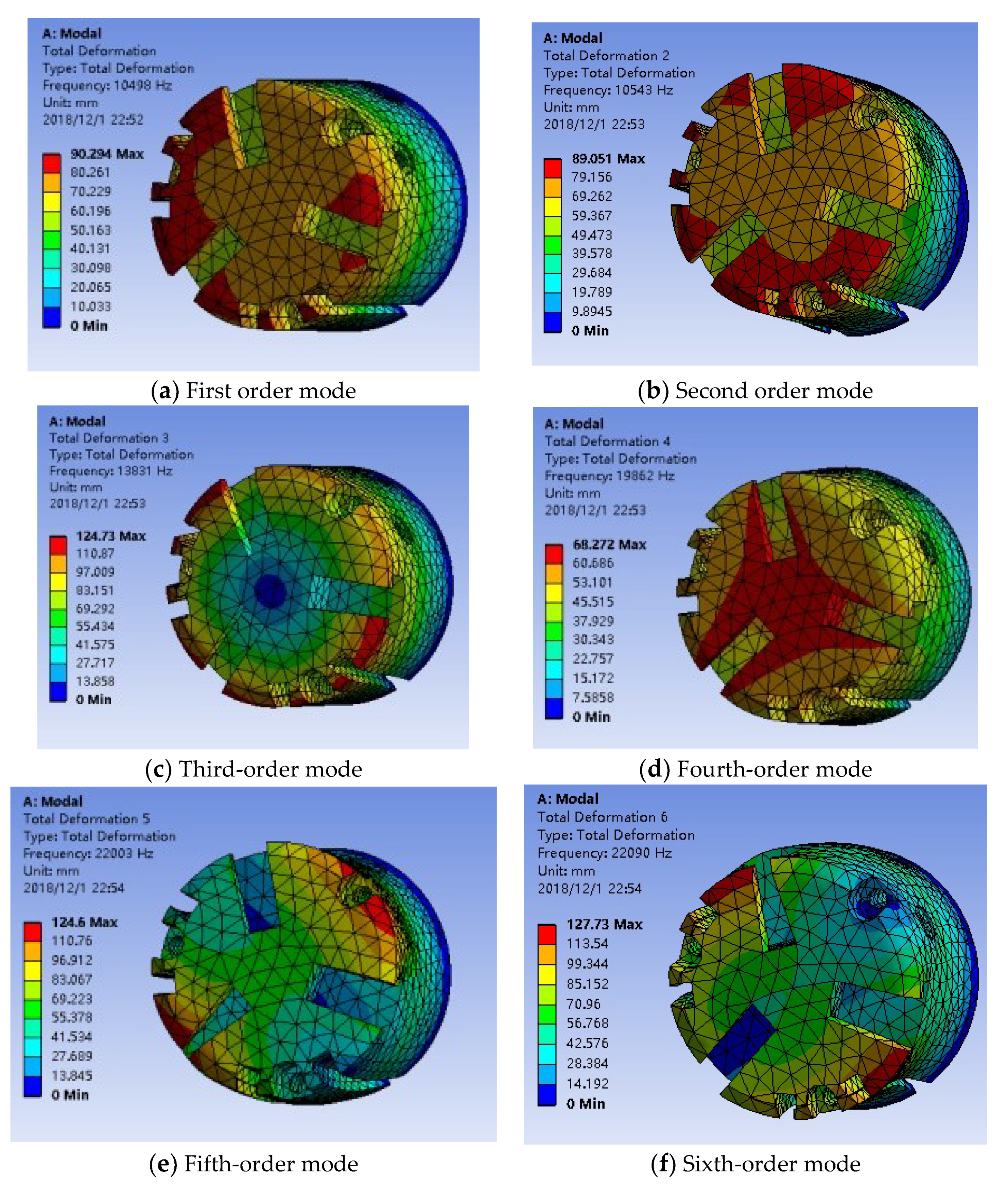
5.1. Simulation Analysis

The optimized data are modeled and imported into ANSYS, and the computer simulation software ANSYS Wrokbench and Pro/E are interfaced and exchanged [22,23]. Before the simulation analysis, the parameters of the model are set and the mesh is divided. In order to reduce the weight of the whole structure and avoid too much power waste. At the same time, high-strength aluminum alloy 6030 is selected as the component material, and some unnecessary features such as screw holes, bolts and so on are removed for analysis. Set the mesh size to 1 mm, separate the guide bar, pallet and turntable and auxiliary components for modal analysis, set boundary conditions and carry out simulation. The first six modes of the rotating seat are shown in Figure 7, and the first six modes of the flange are shown in Figure 8.
According to the simulation results shown in Figure 7 and Figure 8, the first six modal values are within 68 Hz to 125 Hz, especially according to the first three modal values and cloud image analysis, which is far from resonance, which means very stable. It also shows that the structural system data optimized by genetic algorithm is very reliable in actual working conditions.

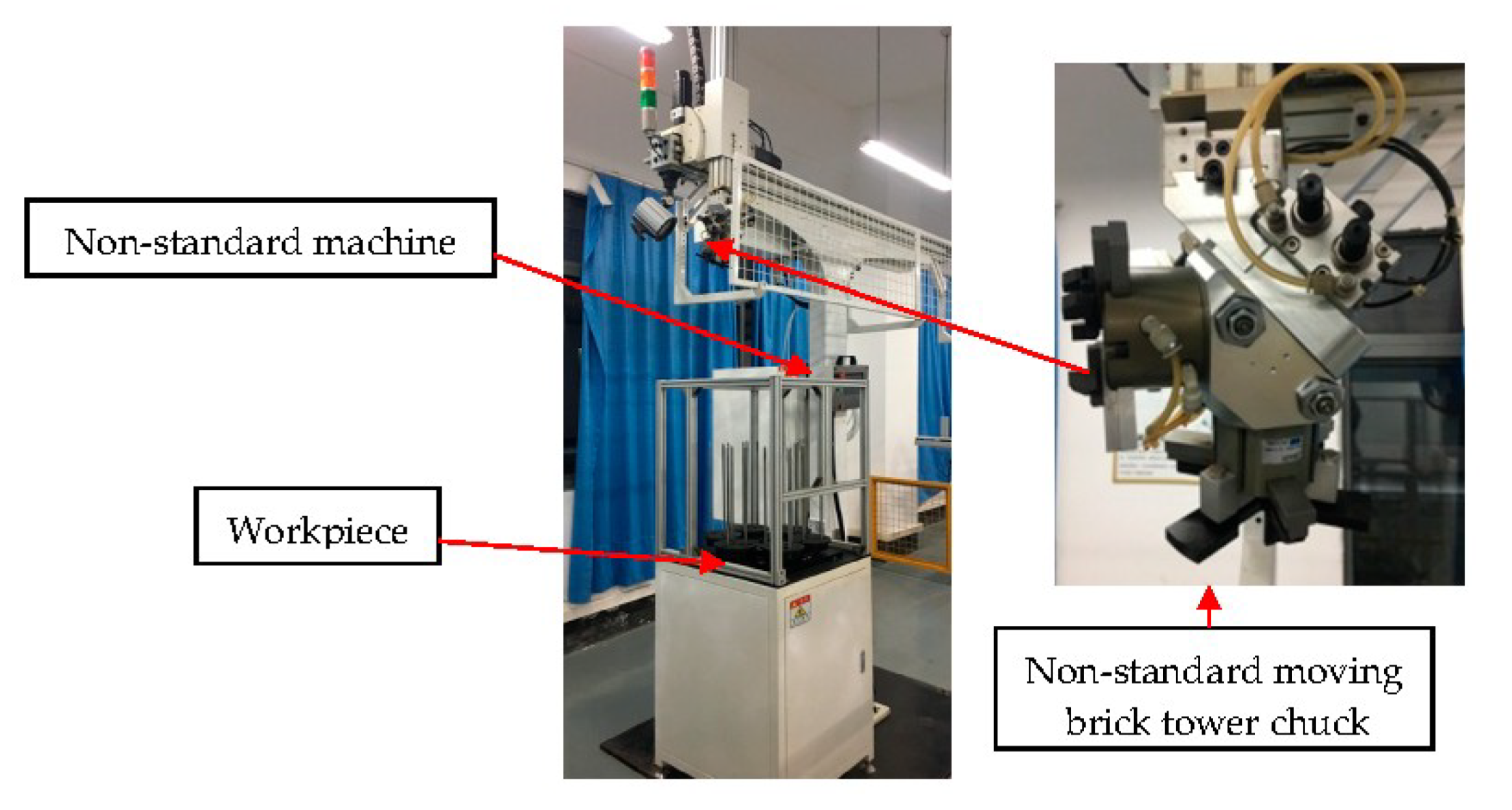
5.2. Physical Verification

The theoretical analysis and simulation results show that it can be used in the design of turret chuck and the structure optimization of key parts, and the results can save the processing cost and improve the production efficiency. Therefore, the data will be combined with the actual processing of physical and work operation. Combined with the production results at present, it is concluded that the feeding speed is 20–30/min and the refueling speed is 1/s switched once for 10 mm thick and diameter workpieces. The physical drawing of the turret chuck loader is shown in Figure 9.

6. Conclusions

(1) In the development of non-standard components, genetic algorithm is used to optimize the key structural system of non-standard components. Mathematical modeling and modal theory modeling of mechanical structure system of turret chuck loading and unloading parts are carried out. Multi-objective optimization is carried out with the lowest cost and the highest efficiency of production materials, and the advantages and disadvantages of GA algorithm data are analyzed by MATLAB tool. Choose one kind of data to carry on the analysis, and obtains is lower than the rest average data value about 4.1%, thus achieves saves the cost, enhances the economic efficiency.
(2) The data structure is modeled by Pro/E and exchanged by ANSYS Wrokbench. The first six order modal values are simulated. The results show that the design steps and the previous optimization analysis method using GA algorithm are reasonable and meet the requirements of the actual working conditions. Therefore, it is put into actual physical processing and put into use in the factory. Combined with the production results at present, it is concluded that the feeding speed is 20–30/min and the refueling speed is 1/s switched once for 10 mm thick and diameter workpieces. At the same time, in addition to the theory and analysis of this research method through the algorithm results of comparative analysis, more important is the feasibility of applying this method to time production. It provides a basis for similar research scholars and actual equipment manufacturers.

Author Contributions

H.L. and Z.L. conceived the overall approach and made the same contribution; Z.H. has made the simulation; C.H. make a contrast in kind according to the actual theory.

Funding

This research was funded by The Chongqing Municipal Higher Education Teaching Reform Major Project in 2017 (171042) and The Industrial Robot Integration Chongqing Higher Vocational and Technical College Application Technology Promotion Center Project (Yu Jiao Ke Fa [2018] No. 2).

Conflicts of Interest

The authors declare no conflict of interest.

References

  1. Zhang, Y.; Lu, C.; Zhang, H.; Fang, Z.F. Workshop layout optimization based on differential cellular multi-objective genetic algorithm. Comput. Integr. Manuf. 2013, 19, 727–734. [Google Scholar]
  2. Li, L.; Gu, W. Mechanical Reliability Design and Analysis; National Defence Industry Press: Beijing, China, 1998. [Google Scholar]
  3. Wirsching, T.Y.T.; Martin, W.S. Advanced fatigue reliability analysis. Int. J. Fatigue 1991, 13, 389–394. [Google Scholar] [CrossRef]
  4. Sinha, A.; Deb, K. Towards understanding evolutionary bilevel multi-objective optimization algorithm. In IFAC Workshop on Control Applications of Optimization; (IFAC-2009); IFAC: Prague, Czech Republic, 2009; Volume 42, pp. 338–343. [Google Scholar]
  5. Li, G.; Long, X.; Zhou, M. A new design method based on feature reusing of the non-standard cam structure for automotive panels stamping dies. J. Intell. Manuf. 2017, 30, 2085–2100. [Google Scholar] [CrossRef]
  6. Jinghua, X.U. Design method of non-standard structure for MEMS based on multi-granularity macro-modeling. J. Mech. Eng. 2011, 47, 97. [Google Scholar]
  7. Pedrero, J.I.; Sánchez, M.B.; Pleguezuelos, M. Load sharing model for non-standard involute spur gears. In New Trends in Mechanism and Machine Science; Springer: Amstrdam, The Netherlands, 2013. [Google Scholar]
  8. Zak, P.; Dynybyl, V. Design and testing of gears with non-standard profile. In Proceedings of the ASME 2007 International Mechanical Engineering Congress and Exposition. American Society of Mechanical Engineers, Seattle, DC, USA, 11–15 November 2007; pp. 105–112. [Google Scholar]
  9. Hedlund, J.; Lehtovaara, A. A parameterized numerical method for generating discrete helical gear tooth surface allowing non-standard geometry. Proc. Inst. Mech. Eng. Part C 2008, 222, 1033–1038. [Google Scholar] [CrossRef]
  10. Zhou, C.; Liu, X.; Chen, W.; Xu, F.; Cao, B. Optimal sliding mode control for an active suspension system based on a genetic algorithm. Algorithms 2018, 11, 205. [Google Scholar] [CrossRef]
  11. Knust, J.; Podszus, F.; Stonis, M. Preform optimization for hot forging processes using genetic algorithms. Int. J. Adv. Manuf. Technol. 2017, 89, 1623–1634. [Google Scholar] [CrossRef]
  12. Zhang, H.; Hua, M.; Dong, G. Optimization of texture shape based on genetic algorithmunder unidirectional sliding. Tribol. Int. 2017, 115, 222–232. [Google Scholar] [CrossRef]
  13. Huang, H.Z.; Qu, J.; Zuo, M.J. Genetic-algorithm-based optimal apportionment of reliability and redundancy under multiple objectives. Iie Trans. 2009, 41, 287–298. [Google Scholar] [CrossRef]
  14. Almeida, J.H.S.; Ribeiro, M.L. Stacking sequence optimization in composite tubes under internal pressure based on genetic algorithm accounting for progressive damage. Compos. Struct. 2017, 178, 20–26. [Google Scholar] [CrossRef]
  15. Yours, A.; Alaa, C. Bechmark study of numerical methods for reliability-based design optimization. Struct. Multidiscip. Optim. 2010, 41, 277–294. [Google Scholar]
  16. Arkat, J.; Farahani, M.H.; Ahmadizar, F. Multi-objective genetic algorithmfor cell formation problemconsidering cellular layout and operations scheduling. Int. J. Comput. Integr. Manuf. 2012, 25, 625–635. [Google Scholar] [CrossRef]
  17. Wang, C.; Zhao, A.; Dong, H.; Li, Z. An improved immune genetic algorithm for distribution network reconfiguration. In Proceedings of the 2nd International Conference on Information Management, Innovation Management and Industrial Engineering, Xi’an, China, 26–27 December 2009; pp. 218–223. [Google Scholar]
  18. Wang, X.; Gao, L.; Zhang, C.; Shao, X. A multi-objective genetic algorithm based on immune and entropy principle for flexible job-shop scheduling problem. Int. J. Adv. Manuf. Technol. 2010, 51, 757–767. [Google Scholar] [CrossRef]
  19. Wang, X.; Gao, L.; Zhang, C.; Li, X. A multi-objective genetic algorithm for fuzzy flexible job-shop scheduling problem. Int. J. Comput. Appl. Technol. 2012, 45, 115–125. [Google Scholar] [CrossRef]
  20. Wei, Q.; Zhu, B.; Jing, B.; Liu, H.; Liu, M. Optimization design of loader steering mechanism based on MATLAB. In Proceedings of the IEEE 10th International Conference on Computer-Aided Industrial Design & Conceptual Design, Wenzhou, China, 26–29 November 2009; pp. 751–754. [Google Scholar]
  21. Liu, J. Simulation of Sliding Mode Control Based on MATLAB; Tsinghua University Press: Beijing, China, 2015; pp. 4–25. [Google Scholar]
  22. Armentani, E.; Caputo, F.; Esposito, L.; Giannella, V.; Citarella, R. Multibody simulation for the vibration analysis of a turbocharged diesel engine. Appl. Sci. 2018, 8, 1192. [Google Scholar] [CrossRef]
  23. Chehouri, A.; Younes, R.; Khoder, J.; Perron, J.; Ilinca, A. A selection process for genetic algorithm using clustering analysis. Algorithms 2017, 10, 123. [Google Scholar] [CrossRef]
Figure 1. Flow chart of a research framework for non-standard component.
Algorithms 12 00169 g001
Figure 2. Three-dimensional drawing of non-standard parts-turret chuck loading and unloading system.
Algorithms 12 00169 g002
Figure 3. GA algorithm flow chart.
Algorithms 12 00169 g003
Figure 4. Simplified quality system diagram of a turret chuck load and unloading machine.
Algorithms 12 00169 g004
Figure 5. Three-dimensional drawing of rotary base.
Algorithms 12 00169 g005
Figure 6. Three-dimensional drawing of the flange.
Algorithms 12 00169 g006
Figure 7. Sixth-order modal cloud diagram of the rotary table.
Algorithms 12 00169 g007
Figure 8. Sixth-order modal cloud diagram of the flange.
Algorithms 12 00169 g008
Figure 9. Physical drawing of turret chuck feeder and feeder.
Algorithms 12 00169 g009
Table 1. Mechanical structure system design variable correspondence table.
Design VariableParameter Code Initial Value/mm Variation Range/mm
D 1 X 1 7065~80
D 2 X 2 4035~50
D 3 X 3 2515~35
D 4 X 4 8065~100
U X 5 10.2~5
H 1 X 6 6050~80
H 2 X 7 5040~75
H 3 X 8 2017~35
L 1 X 9 10080~120
L 2 X 10 9080~110
Table 2. Six groups of genetic algorithms are used to optimize the data.
AlgorithmValueNumber of Iterations
GA78.3440.7720.3470.901.2361.5652.3622.57112.492.2550
71.9746.5619.4486.563.4578.4475.4919.2598.5682.33169
73.6735.7827.7699.562.4379.4569.5626.3782.3690.25241
74.5647.4526.9495.560.5669.2263.5831.0798.4100.570
79.3145.5632.7688.773.2374.1666.6032.5981.76105.378
77.8944.4332.3476.564.3471.1371.5133.35119.8109.491

