
A Review of Natural Joint Systems and Numerical Investigation of Bio-Inspired GFRP-to-Steel Joints

Abstract
:1. Introduction
- comprehend and analyse the functions and the structure of biological joints;
- identify the features that may be transferred from biological to engineering joints;
- devise the most favourable joint configuration that will highlight the identified features by considering the available technology and materials;
- use the available technology, materials and the devised joint configuration to design optimised mechanisms for the specific engineering application.
2. Natural Joint Systems
2.1. Literature Review of Natural Joints
2.1.1. Network Structures
Root Networks
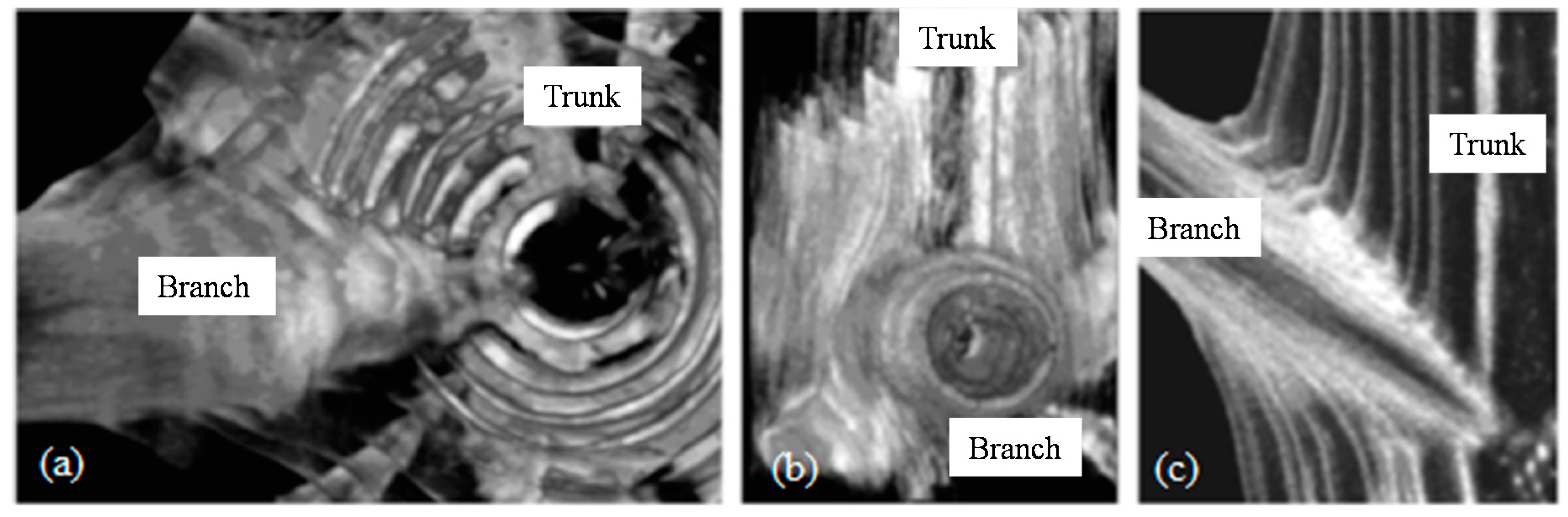
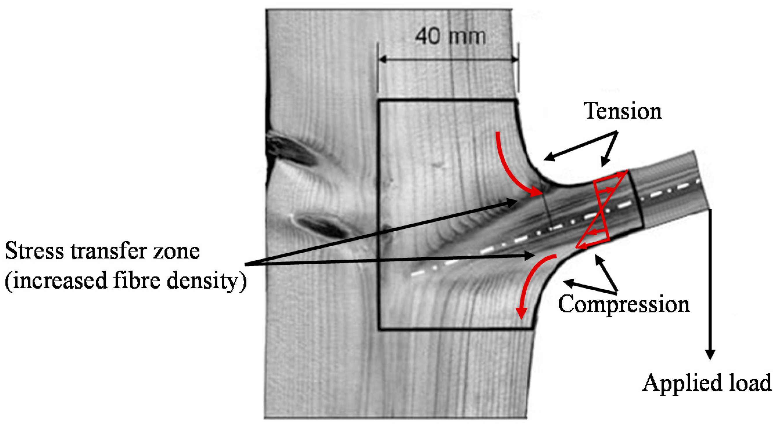
Tree Branches
2.1.2. Transitional Zones of Stiffness
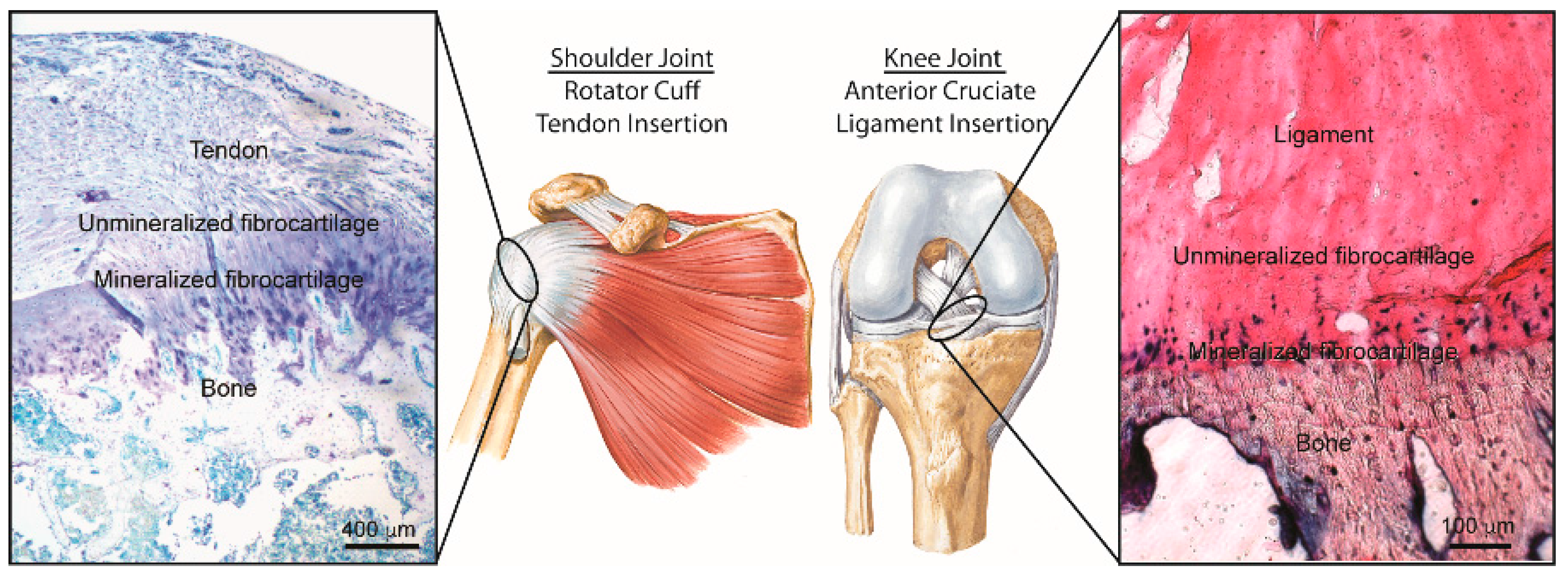
Tendon-to-Bone Attachment
Mussel Anchoring System
2.1.3. Bridging Connections
Fixed Joints
Partially Moveable Joints
Highly Moveable
2.1.4. Hooks
2.1.5. Adhesives
2.1.6. Insect Wing Joints
2.2. Discussion of Natural Joints
2.2.1. Structural Complexity
2.2.2. Material Complexity
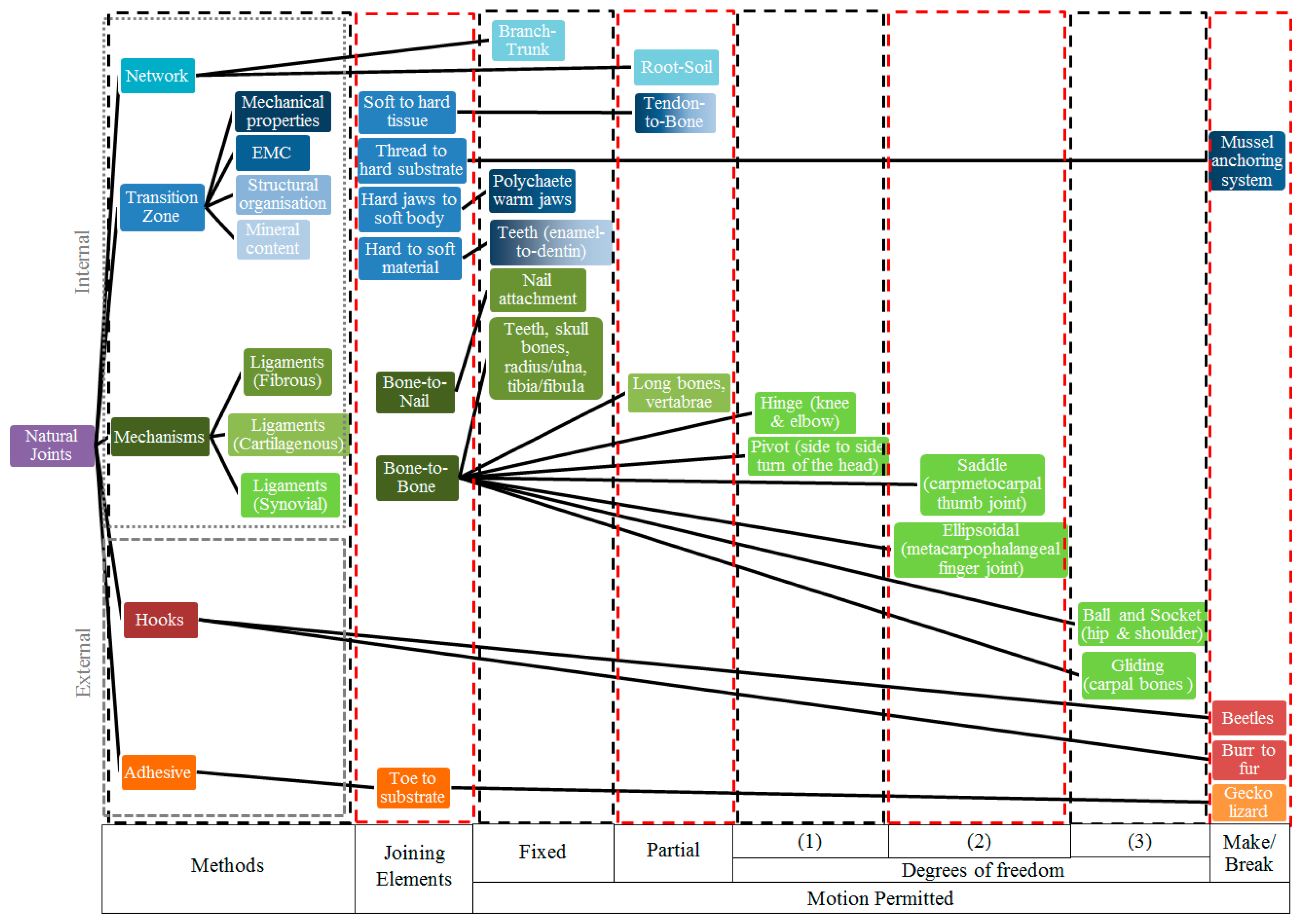
2.2.3. Taxonomy Chart of Natural Joints
2.3. Comparison between Natural and Engineering Joints
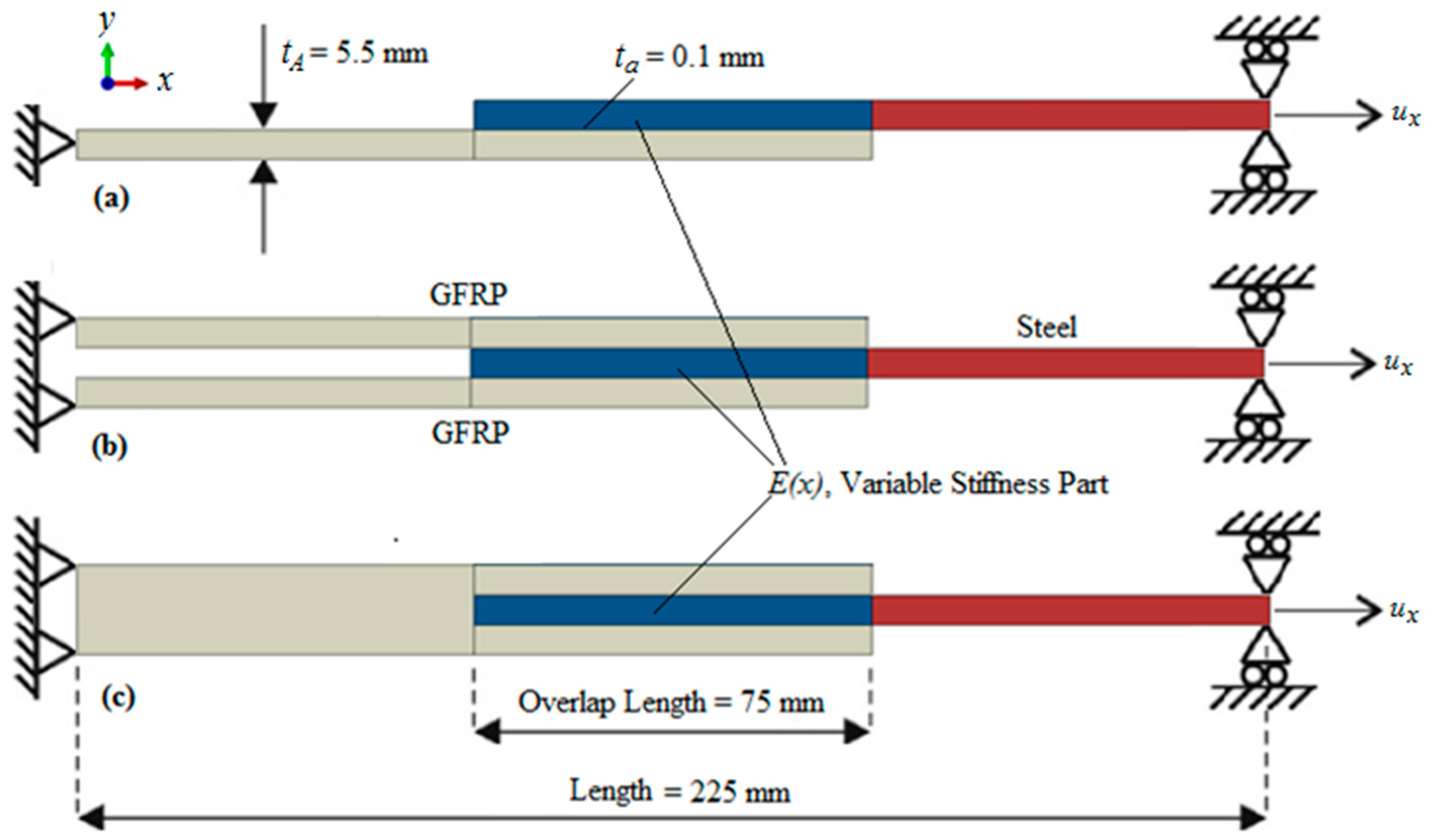
3. Bio-Inspired GFRP to Steel Joints
3.1. Materials and Methods
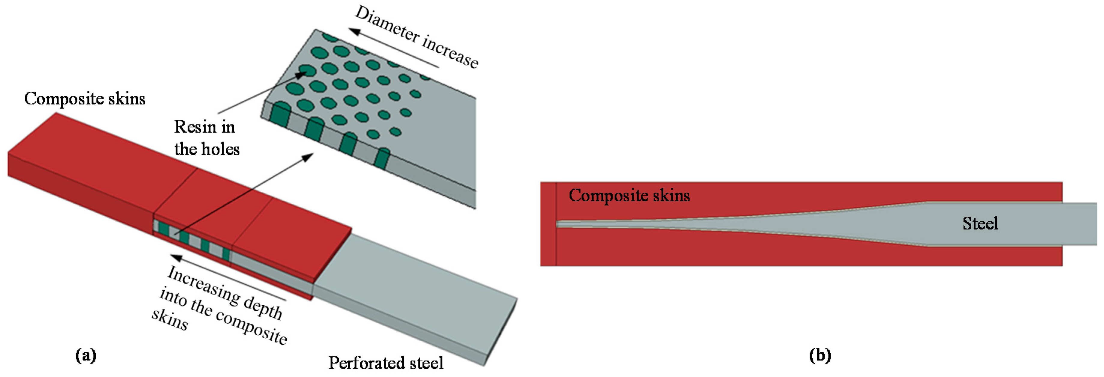
3.1.1. Finite Element Model Implementation
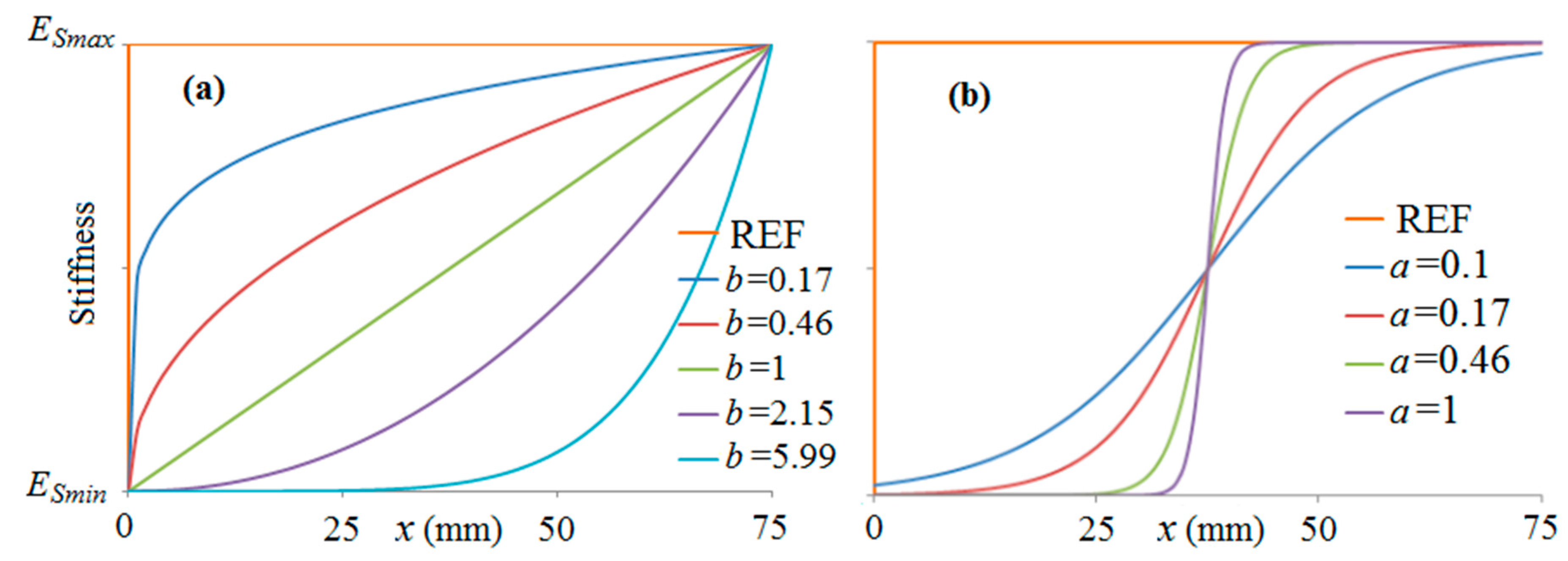
3.1.2. Stiffness Variation in Overlap
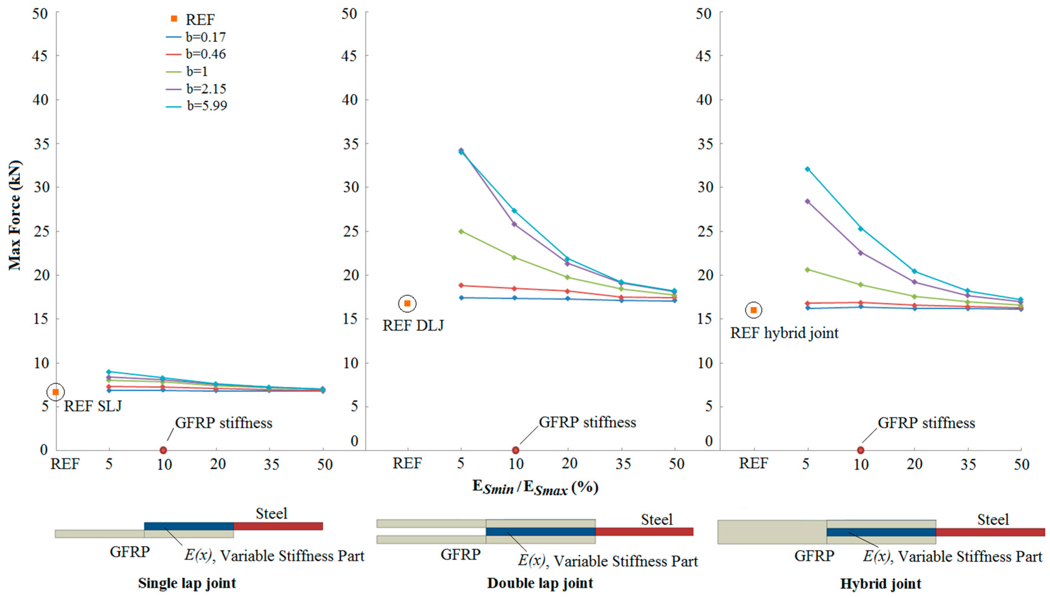
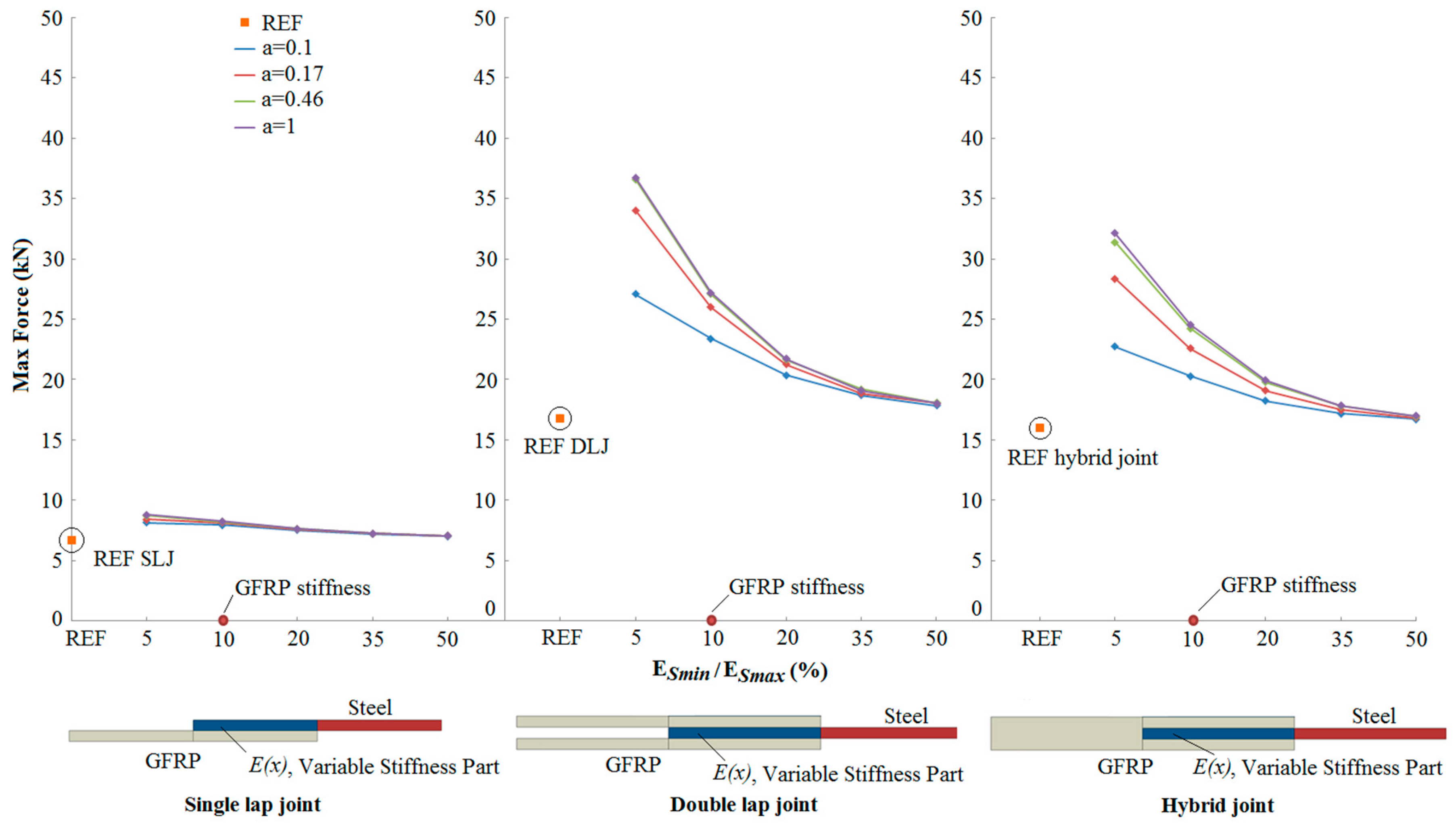
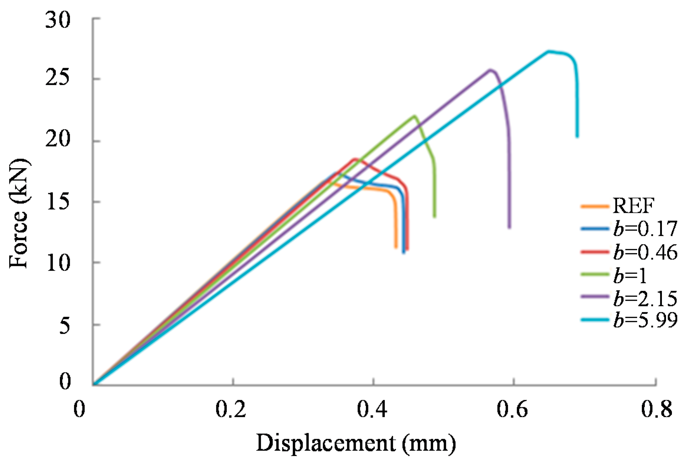
3.2. Results
4. Conclusions
- An increase in the joint strength was observed as the reduced stiffness of the steel adherend approached the stiffness of the GFRP adherend.
- Compared to reference joints (with no transitional zone of stiffness between the adherends), bio-inspired joints showed a 118% increase of joint strength for the best case.
- The strength increase depends significantly on the form of stiffness variation within the overlap region.
- The potential for increased strength is greater in the double lap and hybrid joints, compared to the single lap joint.
Supplementary Materials
Acknowledgments
Author Contributions
Conflicts of Interest
Abbreviations
| 3D | three dimensional; |
| CFRP | Carbon fibre reinforced plastic; |
| CZM | Cohesive zone model; |
| DLJ | Double lap joint; |
| CFRP | Carbon fibre reinforced plastic; |
| GFRP | Glass fibre reinforced plastic; |
| OL | Overlap length; |
| REF | Reference; |
| SLJ | Single lap joint |
References
- Banea, M.D.; da Silva, L.F.M. Adhesively bonded joints in composite materials: An overview. J. Mater. Des. Appl. 2009, 223, 1–18. [Google Scholar] [CrossRef]
- Campilho, R.D.S.G.; Banea, M.D.; Neto, J.A.B.P.; da Silva, L.F.M. Modelling of single-lap joints using cohesive zone models: Effect of the cohesive parameters on the output of the simulations. J. Adhes. 2012, 88, 513–533. [Google Scholar] [CrossRef]
- Anyfantis, K.N. Finite element predictions of composite-to-metal bonded joints with ductile adhesive materials. Compos. Struct. 2012, 94, 2632–2639. [Google Scholar] [CrossRef]
- Anyfantis, K.N.; Tsouvalis, N.G. Loading and fracture response of CFRP-to-steel adhesively bonded joints with thick adherents—Part I: Experiments. Compos. Struct. 2013, 96, 850–857. [Google Scholar] [CrossRef]
- Anyfantis, K.N.; Tsouvalis, N.G. Loading and fracture response of CFRP-to-steel adhesively bonded joints with thick adherents—Part II: Numerical simulation. Compos. Struct. 2013, 96, 858–868. [Google Scholar] [CrossRef]
- Lees, J.M. Behaviour of GFRP adhesive pipe joints subjected to pressure and axial loadings. Compos. Part A 2006, 37, 1171–1179. [Google Scholar] [CrossRef]
- Avgoulas, E.I.; Sutcliffe, M.P.F. Biomimetic-inspired joining of composite with metal structures: A survey of natural joints and application to single lap joints. In Proceedings of the SPIE Smart Structures and Materials Conference on Bioinspiration, Biomimetics, and Bioreplication IV, San Diego, CA, USA, 9–13 March 2014.
- Vincent, J.F.V. Biomimetics—A review. Proc. Inst. Mech. Eng. Part H J. Eng. Med. 2009, 223, 919–939. [Google Scholar] [CrossRef]
- Wegst, U.G.K.; Bai, H.; Saiz, E.; Tomsia, A.P.; Ritchie, R.O. Bioinspired structural materials. Nat. Mater. 2015, 14, 23–36. [Google Scholar] [CrossRef] [PubMed]
- Bach, D.; Schmich, F.; Masselter, T.; Speck, T. A review of selected pumping systems in nature and engineering—Potential biomimetic concepts for improving displacement pumps and pulsation damping. Bioinspir. Biomim. 2015, 10, 1–28. [Google Scholar] [CrossRef] [PubMed]
- Buschmann, T.; Ewald, A.; von Twickel, A.; Büschges, A. Controlling legs for locomotion—Insights from robotics and neurobiology. Bioinspir. Biomim. 2015, 10, 1–38. [Google Scholar] [CrossRef] [PubMed]
- Raj, A.; Thakur, A. Fish-inspired robots: Design, sensing, actuation, and autonomy—A review of research. Bioinspir. Biomim. 2016, 11, 1–23. [Google Scholar] [CrossRef] [PubMed]
- Sakes, A.; Dodou, D.; Breedveld, P. Buckling prevention strategies in nature as inspiration for improving percutaneous instruments: A review. Bioinspir. Biomim. 2016, 11, 1–27. [Google Scholar] [CrossRef] [PubMed]
- Abdulbari, H.A.; Mahammed, H.D.; Hassan, Z.B.Y. Bio-Inspired Passive Drag Reduction Techniques: A Review. ChemBioEng Rev. 2015, 2, 185–203. [Google Scholar] [CrossRef]
- Zheng, Y.J.; Chen, S.Y.; Lin, Y.; Wang, W.L. Bio-Inspired Optimization of Sustainable Energy Systems: A Review. Math. Probl. Eng. 2013. [Google Scholar] [CrossRef]
- Bello, O.S.; Adegoke, K.A.; Oyewole, R.O. Biomimetic Materials in Our World: A Review. J. Appl. Chem. 2013, 5, 22–35. [Google Scholar]
- Wang, X.; Ding, B.; Li, B. Biomimetic electrospun nanofibrous structures for tissue engineering. Mater. Today 2013, 16, 229–241. [Google Scholar] [CrossRef] [PubMed]
- Liu, K.; Jiang, L. Bio-Inspired Self-Cleaning Surfaces. Ann. Rev. Mater. Res 2012, 42, 231–63. [Google Scholar] [CrossRef]
- Scardino, A.J.; de Nys, R. Mini review: Biomimetic models and bioinspired surfaces for fouling control. Biofouling 2011, 27, 73–86. [Google Scholar] [CrossRef] [PubMed]
- Srinivasan, A.V.; Haritos, G.K.; Hedberg, F.L.; Jones, W.F. Biomimetics: Advancing Man-Made Materials through Guidance from Nature—An Update. Appl. Mech. Rev. 1996, 49, 194–200. [Google Scholar] [CrossRef]
- Vertechy, R.; Parenti-Castelli, V. Biologically Inspired Joints for Innovative Articulations Concepts; ESA: Bologna, Italy, 2005. [Google Scholar]
- Abe, K.; Ziemer, R.R. Effect of tree roots on a shear zone—Modelling reinforced shear-stress. Can. J. For. Res. 1991, 21, 1012–1019. [Google Scholar] [CrossRef]
- Coutts, M.P. Root architecture and tree stability. Plant Soil 1983, 71, 171–188. [Google Scholar] [CrossRef]
- Gyssels, G.; Poesen, J. The importance of plant root characteristics in controlling concentrated flow erosion rates. Earth Surf. Process Landf. 2003, 28, 371–384. [Google Scholar] [CrossRef]
- Waisel, Y.; Eshel, A.; Kafkafi, U. Plant Roots: The Hidden Half; Marcel Dekker: New York, NY, USA, 2002. [Google Scholar]
- Encyclopedia Britannica. Available online: http://www.britannica.com/science/root-plant (accessed on 8 April 2016).
- Burns, L.A.; Mouritz, A.P.; Pook, D.; Feih, S. Bio-inspired design of aerospace composite joints for improved damage tolerance. Compos. Struct. 2012, 94, 995–1004. [Google Scholar] [CrossRef]
- Müller, U.; Gindl, W.; Jeronimidis, G. Biomechanics of a branch-stem junction in softwood. Trees Struct. Funct. 2006, 20, 643–648. [Google Scholar] [CrossRef]
- Mattheck, C.; Bethge, K. The structural optimisation of trees. Naturwissenschaften 1998, 85, 1–10. [Google Scholar] [CrossRef]
- Burns, L.A.; Mouritz, A.P.; Pook, D.; Feih, S. Strength improvement to composite T-joints under bending through bio-inspired design. Compos. Part A 2012, 43, 1971–1980. [Google Scholar] [CrossRef]
- Waite, J.H.; Lichtenegger, H.C.; Stucky, G.D.; Hansma, P. Exploring molecular and mechanical gradients in structural bioscaffolds. Biochemistry 2004, 43, 7653–7662. [Google Scholar] [CrossRef] [PubMed]
- Lichtenegger, H.C.; Schöberl, T.; Ruokolainen, J.; Cross, J.O.; Heald, S.M.; Birkedal, H.; Waite, J.H.; Stucky, G.D. Zinc and mechanical prowess in the jaws of Nereis, a marine worm. Proc. Natl. Acad. Sci. USA 2003, 100, 9144–9149. [Google Scholar] [CrossRef] [PubMed]
- Bostrom, M.P.G.; Boskey, A.; Kaufman, J.J.; Einhorn, T.A. Form and function of bone. In Orthopaedic Basic Science, 2nd ed.; Buckwalter, J.A., Einhorn, T.A., Simon, S.R., Eds.; American Academy of Orthopaedic Surgeons: Park Ridge, IL, USA, 2000; pp. 319–370. [Google Scholar]
- Benjamin, M.; Toumi, H.; Ralphs, J.R.; Bydder, G.; Best, T.M.; Milz, S. Where tendons and ligaments meet bone: Attachment sites (‘entheses’) in relation to exercise and/or mechanical load. J. Anat. 2006, 208, 471–790. [Google Scholar] [CrossRef] [PubMed]
- Thomopoulos, S.; Genin, G.M.; Galatz, L.M. The development and morphogenesis of the tendon-to-bone insertion—What development can teach us about healing. J. Musculoskelet. Neuronal Interact. 2010, 10, 35–45. [Google Scholar] [PubMed]
- Milz, S.; Schluter, T.; Putz, R.; Moriggl, B.; Ralphs, J.R.; Benjamin, M. Fibrocartilage in the transverse ligament of the human atlas. Spine 2001, 15, 1765–1771. [Google Scholar] [CrossRef]
- Benjamin, M.; Kumai, T.; Milz, S.; Boszczyk, B.M.; Boszczyk, A.A.; Ralphs, J.R. The skeletal attachment of tendons-tendon ‘entheses’. Comp. Biochem. Physiol. Part A Mol. Integr. Physiol. 2002, 133, 931–945. [Google Scholar] [CrossRef]
- Lu, H.H.; Thomopoulos, S. Functional Attachment of Soft Tissues to Bone: Development, Healing, and Tissue Engineering. Ann. Rev. Biomed. Eng. 2013, 15, 201–226. [Google Scholar] [CrossRef] [PubMed]
- Waggett, A.D.; Ralphs, J.R.; Kwan, A.P.; Woodnutt, D.; Benjamin, M. Characterization of collagens and proteoglycans at the insertion of the human Achilles tendon. Matrix Biol. 1998, 16, 457–470. [Google Scholar] [CrossRef]
- Kumagai, J.; Sarkar, K.; Uhthoff, H.K.; Okawara, Y.; Ooshima, A. Immunohistochemical distribution of type I, II and III collagens in the rabbit supraspinatus tendon insertion. J. Anat. 1994, 185, 279–284. [Google Scholar] [PubMed]
- Visconti, S.C.; Kavalkovich, K.; Wu, J.; Niyibizi, C. Biochemical analysis of collagens at the ligament-bone interface reveals presence of cartilage-specific collagens. Arch. Biochem. Biophys. 1996, 328, 135–142. [Google Scholar] [CrossRef]
- Fukuta, S.; Oyama, M.; Kavalkovich, K.; Fu, F.H.; Niyibizi, C. Identification of types II, IX and X collagens at the insertion site of the bovine achilles tendon. Matrix Biol. 1998, 17, 65–73. [Google Scholar] [CrossRef]
- Thomopoulos, S. Structure, biomechanics, and mechanobiology in the attachment of tendon to bone. In Proceedings of the 55th Meeting of the Orthopaedic Research Society, Las Vegas, NV, USA, 24 February 2009.
- Suresh, S. Graded materials for resistance to contact deformation and damage. Science 2001, 292, 2447–2451. [Google Scholar] [CrossRef] [PubMed]
- Allen, J.A.; Cook, M.; Jackson, D.J.; Preston, S.; Worth, E.M. Observations on the rate of production and mechanical properties of the byssus threads of Mytilus edulis. J. Molluscan Stud. 1976, 42, 279–289. [Google Scholar]
- Meadows, P.S.; Shand, P. Experimental analysis of byssus thread production by Mytilus edulis and Modiolus modiolus in sediments. Mar. Biol. 1989, 101, 219–226. [Google Scholar] [CrossRef]
- Crisp, D.J.; Walker, G.; Young, G.A.; Yule, A.B. Adhesion and substrate choice in mussels and barnacles. J. Colloid Interface Sci. 1985, 104, 40–50. [Google Scholar] [CrossRef]
- Smeathers, J.E.; Vincent, J.F.V. Mechanical properties of mussel byssus threads. J. Molluscan Stud. 1979, 45, 219–230. [Google Scholar]
- Qin, X.; Waite, J.H. Exotic collagen gradients in the byssus of the mussel Mytilus edulis. J. Exp. Biol. 1995, 198, 633–644. [Google Scholar] [PubMed]
- Gosline, J.M.; Lillie, M.; Carrington, E.; Guerette, P.A.; Ortlepp, C.S.; Savage, K.N. Elastomeric proteins: Biological roles and mechanical properties. Philos. Trans. R. Soc. B 2002, 357, 121–132. [Google Scholar] [CrossRef] [PubMed]
- Moore, K.L.; Agur, A.M.R.; Dalley, A.F. Essential Clinical Anatomy, 4th ed.; Lippincott Williams & Wilkins: Baltimore, MD, USA, 2011. [Google Scholar]
- Wolf, H.F.; Rateitschak, K.H. Periodontology; Thieme Stuttgart: New York, NY, USA, 2005. [Google Scholar]
- Hubbard, R.P.; Melvin, J.W.; Barodawala, I.T. Flexure of cranial sutures. J. Biomech. 1971, 4, 491–496. [Google Scholar] [CrossRef]
- Jaslow, C.R. Mechanical properties of cranial sutures. J. Biomech. 1990, 23, 313–321. [Google Scholar] [CrossRef]
- Jasinoski, S.C.; Reddy, B.D.; Louw, K.K.; Chinsamy, A. Mechanics of cranial sutures using the finite element method. J. Biomech. 2010, 43, 3104–3111. [Google Scholar] [CrossRef] [PubMed]
- Li, Y.; Ortiz, C.; Boyce, M.C. Stiffness and strength of suture joints in nature. Phys. Rev. E 2011, 84, 062904. [Google Scholar] [CrossRef] [PubMed]
- Li, Y.; Ortiz, C.; Boyce, M.C. Bioinspired, mechanical, deterministic fractal model for hierarchical suture joints. Phys. Rev. E 2012, 85, 031901. [Google Scholar] [CrossRef] [PubMed]
- Moazen, M.; Curtis, N.; O'Higgins, P.; Jones, M.E.H.; Evans, S.E.; Fagan, M.J. Assessment of the role of sutures in a lizard skull: A computer modelling study. Proc. R. Soc. Lond. B 2009, 276, 39–46. [Google Scholar] [CrossRef] [PubMed]
- De Blasio, F.V. The role of suture complexity in diminishing strain and stress in ammonoid phragmocones. Lethaia 2008, 41, 15–24. [Google Scholar] [CrossRef]
- Jasinoski, S.C.; Reddy, B.D. Mechanics of cranial sutures during simulated cyclic loading. J. Biomech. 2012, 45, 2050–2054. [Google Scholar] [CrossRef] [PubMed]
- Zhang, Z.Q.; Yang, J.L. Biomechanical Dynamics of Cranial Sutures during Simulated Impulsive Loading. Appl. Bionics Biomech. 2015. [Google Scholar] [CrossRef] [PubMed]
- Rafferty, K.L.; Herring, S.W. Craniofacial sutures: Morphology, growth, andin vivo masticatory strains. J. Morphol. 1999, 242, 167–179. [Google Scholar] [CrossRef]
- Rafferty, K.L.; Herring, S.W.; Marshall, C.D. Biomechanics of the rostrum and the role of facial sutures. J. Morphol. 2003, 257, 33–44. [Google Scholar] [CrossRef] [PubMed]
- Krauss, S.; Monsonego-Ornan, E.; Zelzer, E.; Fratzl, P.; Shahar, R. Mechanical Function of a Complex Three-Dimensional Suture Joining the Bony Elements in the Shell of the Red-Eared Slider Turtle. Adv. Mater. 2009, 21, 407–412. [Google Scholar] [CrossRef]
- Warren, S.M.; Brunet, L.J.; Harland, R.M.; Economides, A.N.; Longaker, M.T. The BMP antagonist noggin regulates cranial suture fusion. Nature 2013, 422, 625–629. [Google Scholar] [CrossRef] [PubMed]
- Motherway, J.A.; Verschueren, P.; Van der Perre, G.; Sloten, J.V.; Gilchrist, M.D. The mechanical properties of cranial bone: The effect of loading rate and cranial sampling position. J. Biomech. 2009, 42, 2129–2135. [Google Scholar] [CrossRef] [PubMed]
- Wang, Q.; Opperman, L.A.; Havill, L.M.; Carlson, D.S.; Dechow, P.C. Inheritance of sutural pattern at the pterion in rhesus monkey skulls. Anat. Rec. Part A Discov. Mol. Cell. Evolut. Biol. 2006, 288, 1042–1049. [Google Scholar] [CrossRef] [PubMed]
- Arciszewski, T.; Cornell, J. Intelligent Computing in Engineering and Architecture; Springer: Berlin, Germany, 2006. [Google Scholar]
- Berker, D.A.R.; Baran, R. Science of the Nail Apparatus. In Diseases of the Nails and their Management, 4th ed.; Baran, R., Berker, D.A.R., Holzberg, M., Thomas, L., Eds.; John Wiley & Sons: New York, NY, USA, 2012. [Google Scholar]
- Lewis, B.L. Microscopic studies of fetal and mature nail and surrounding soft tissue. AMA Arch. Dermatol. Syphilol. 1954, 70, 733–747. [Google Scholar] [CrossRef]
- Dawber, R.P.; Baran, R. 1994 Structure, embryology, comparative anatomy, and physiology of the nail. In Diseases of the Nails and their Management; Baran, R., Dawber, R.P., Eds.; Blackwell Science: Oxford, UK, 1994; pp. 1–24. [Google Scholar]
- Lawry, M.; Rich, P. The Nail Apparatus: A Guide for Basic and Clinical Science. Curr. Probl. Dermatol. 1999, 11, 1–47. [Google Scholar] [CrossRef]
- Sinclair, R.D.; Wojnarowska, F.; Leigh, I.M.; Dawber, R.P.R. The basement membrane zone of the nail. J. Dermatol. 1994, 131, 499–505. [Google Scholar] [CrossRef]
- Drape, J.L.; Wolfram-Gabel, R.; Idy-Peretti, I.; Baran, R.; Goettmann, S.; Sick, H.; Guérin-Surville, H.; Bittoun, J. The lunula: A magnetic resonance imaging approach to the subnail matrix area. J. Investig. Dermatol. 1996, 106, 1081–1085. [Google Scholar] [CrossRef] [PubMed]
- DonTigny, R.L. Function and Pathomechanics of the Sacroiliac Joint. J. Am. Phys. Ther. Assoc. 1985, 65, 35–44. [Google Scholar]
- Alderink, G.J. The Sacroiliac Joint: Review of Anatomy, Mechanics, and Function. J. Orthop. Sports Phys. Ther. 1991, 13, 71–84. [Google Scholar] [CrossRef] [PubMed]
- Encyclopedia. Joint (in Anatomy). Available online: http://www.encyclopedia.com/topic/joint.aspx#2 (accessed on 20 April 2016).
- Masouros, S.D.; Bull, A.M.J.; Amis, A.A. Biomechanics of the knee joint. Orthop. Trauma 2010, 24, 84–91. [Google Scholar] [CrossRef]
- Adouni, M.; Shirazi-Adl, A.; Shirazi, R. Computational biodynamics of human knee joint in gait: From muscle forces to cartilage stresses. J. Biomech. 2012, 45, 2149–2156. [Google Scholar] [CrossRef] [PubMed]
- Sarma, A.; Borgohain, B.; Saikia, B. Proximal tibiofibular joint: Rendezvous with a forgotten articulation. Indian J. Orthop. 2015, 49, 489–945. [Google Scholar] [PubMed]
- Scott, J.; Lee, H.; Barsoum, W.; van den Bogert, A.J. The effect of tibiofemoral loading on proximal tibiofibular joint motion. J. Anat. 2007, 211, 647–653. [Google Scholar] [CrossRef] [PubMed]
- Mesfar, W.; Shirazi-Adl, A. Biomechanics of the knee joint in flexion under various quadriceps forces. Knee 2005, 12, 424–434. [Google Scholar] [CrossRef] [PubMed]
- Lucas, D.B. Biomechanics of the Shoulder Joint. Arch. Surg. 1973, 107, 425–432. [Google Scholar] [CrossRef] [PubMed]
- Macirowski, T.; Tepic, S.; Mann, R.W. Cartilage Stresses in the Human Hip Joint. J. Biomech. Eng. 1994, 116, 10–18. [Google Scholar] [CrossRef] [PubMed]
- Anderson, A.E.; Ellis, B.J.; Maas, S.A.; Peters, C.L.; Weiss, J.A. Validation of Finite Element Predictions of Cartilage Contact Pressure in the Human Hip Joint. J. Biomech. Eng. 2008. [Google Scholar] [CrossRef] [PubMed]
- Henak, C.R.; Ateshian, G.A.; Weiss, J.A. Finite Element Prediction of Transchondral Stress and Strain in the Human Hip. J. Biomech. Eng. 2013. [Google Scholar] [CrossRef] [PubMed]
- Pieron, A.P. The Mechanism of the First Carpometacarpal (CMC) Joint: An Anatomical and Mechanical Analysis. Acta Orthop. Scand. 1973, 44, 1–104. [Google Scholar] [CrossRef]
- Kuczynski, K. Carpometacarpal joint of the human thumb. J. Anat. 1974, 118, 119–126. [Google Scholar] [CrossRef] [PubMed]
- Ateshian, G.A.; Ark, J.W.; Rosenwasser, M.P.; Pawluk, R.J.; Soslowsky, L.J.; Mow, V.C. Contact areas in the thumb carpometacarpal joint. J. Orthop. Res. 1995, 13, 450–458. [Google Scholar] [CrossRef] [PubMed]
- Pagowski, S.; Piekarski, K. Biomechanics of metacarpophalangeal joint. J. Biomech. 1977, 10, 205–209. [Google Scholar] [CrossRef]
- Kauer, J.M. The mechanism of the carpal joint. Clin. Orthop. Relat. Res. 1986, 202, 16–26. [Google Scholar] [CrossRef] [PubMed]
- Kauer, J.M.; de Lange, A. The carpal joint. Anatomy and function. Hand Clin. 1987, 3, 23–29. [Google Scholar] [PubMed]
- Velcro Industries, B.V. Available online: http://www.velcro.com (accessed on 12 April 2016).
- Chen, Q.; Gorb, S.N.; Gorb, E.; Pugno, N. Mechanics of plant fruit hooks. J. R. Soc. Interface 2013, 10, 1–7. [Google Scholar] [CrossRef] [PubMed]
- Bauer, G.; Klein, M.C.; Gorb, S.N.; Speck, T.; Voigt, D.; Gallenmüller, F. Always on the bright side: The climbing mechanism of Galium aparine. Proc. R. Soc. B 2011, 278, 2233–2239. [Google Scholar] [CrossRef] [PubMed]
- Gorb, E.; Gorb, S. Contact separation force of the fruit burrs in four plant species adapted to dispersal by mechanical interlocking. Plant Physiol. Biochem. 2002, 40, 373–381. [Google Scholar] [CrossRef]
- Saunders, B.E. A biomimetic study of natural attachment mechanisms—Arctium minus part 1. Robot. Biomim. 2015. [Google Scholar] [CrossRef]
- Saunders, B.E. A biomimetic study of natural attachment mechanisms: Imaging cellulose and chitin part 2. Robot. Biomim. 2015. [Google Scholar] [CrossRef] [PubMed]
- Gorb, E.V.; Popov, V.L.; Gorb, S.N. Natural Hook-and-loop Fasteners: Anatomy, Mechanical Properties, And Attachment Force of the Jointed Hooks of The Galium Aparine Fruit. WIT Trans. Ecol. Environ. 2002, 57. [Google Scholar] [CrossRef]
- Song, Y.; Dai, Z.; Wang, Z.; Ji, A.; Gorb, S.N. The synergy between the insect-inspired claws and adhesive pads increases the attachment ability on various rough surfaces. Sci. Rep. 2016, 6. [Google Scholar] [CrossRef] [PubMed]
- Geim, A.K.; Dubonos, S.V.; Grigorieva, I.V.; Novoselov, K.S.; Zhukov, A.A.; Shapoval, S.Y. Microfabricated adhesive mimicking gecko foot-hair. Nat. Mater. 2003, 2, 461–463. [Google Scholar] [CrossRef] [PubMed]
- Autumn, K.; Peattie, A. Mechanisms of adhesion in geckos. Integr. Comp. Biol. 2002, 42, 1081–1090. [Google Scholar] [CrossRef] [PubMed]
- Arzt, E.; Gorb, S.; Spolenak, R. From micro to nano contacts in biological attachment devices. Proc. Natl. Acad. Sci. USA 2003, 100, 10603–10606. [Google Scholar] [CrossRef] [PubMed]
- Bhushan, B. Gecko Feet: Natural Hairy Attachment Systems for Smart Adhesion—Mechanism, Modeling and Development of Bio-Inspired Materials. In Nanotribology and Nanomechanics; Springer: Berlin/Heidelberg, Germany, 2008; pp. 1073–1134. [Google Scholar]
- Kesel, A.B.; Martin, A.; Seidl, T. Adhesion measurements on the attachment devices of the jumping spider evarcha arcuate. J. Exp. Biol. 2003, 206, 2733–2738. [Google Scholar] [CrossRef] [PubMed]
- Autumn, K.; Liang, Y.A.; Hsieh, S.T.; Zesch, W.; Chan, W.P.; Kenny, T.W.; Fearing, R.; Full, R.J. Adhesive force of a single gecko foot-hair. Nature 2000, 405, 681–685. [Google Scholar] [PubMed]
- Autumn, K.; Sitti, M.; Liang, Y.A.; Peattie, A.M.; Hansen, W.R.; Sponberg, S.; Kenny, T.W.; Fearing, R.; Israelachvili, J.N.; Full, R.J. Evidence for van der Waals adhesion in gecko setae. Proc. Natl. Acad. Sci. USA 2002, 99, 12252–12256. [Google Scholar] [CrossRef] [PubMed]
- Beutel, R.G.; Gorb, S.N. Ultrastructure of attachment specializations of hexapods (Arthropoda): Evolutionary patterns inferred from a revised ordinal phylogeny. J. Zool. Syst. Evol. Res. 2001, 39, 177–207. [Google Scholar] [CrossRef]
- Gorb, S.N. Biological attachment devices: Exploring nature’s diversity for biomimetics. Philos. Trans. R. Soc. A 2008, 366, 1557–1574. [Google Scholar] [CrossRef] [PubMed]
- Dai, Z.; Gorb, S.N.; Schwarz, U. Roughness-dependent friction force of the tarsal claw system in the beetle Pachnoda marginata (Coleoptera, Scarabaeidae). J. Exp. Biol. 2002, 205, 2479–2488. [Google Scholar] [PubMed]
- Bullock, J.M.R.; Federle, W. The effect of surface roughness on claw and adhesive hair performance in the dock beetle Gastrophysa viridula. Insect Sci. 2011, 18, 298–304. [Google Scholar] [CrossRef]
- Voigt, D.; Schuppert, J.M.; Dattinger, S.; Gorb, S.N. Sexual dimorphism in the attachment ability of the Colorado potato beetle Leptinotarsa decemlineata (Coleoptera: Chrysomelidae) to rough substrates. J. Insect Physiol. 2008, 54, 765–776. [Google Scholar] [CrossRef] [PubMed]
- Ditsche, K.P.; Barthlott, W.; Koop, J.H. At which surface roughness do claws cling? Investigations with larvae of the running water mayfly Epeorus assimilis (Heptageniidae, Ephemeroptera). Zoology 2012, 115, 379–838. [Google Scholar] [CrossRef] [PubMed]
- Langer, M.G.; Ruppersberg, J.P.; Gorb, S.N. Adhesion forces measured at the level of a terminal plate of the fly’s seta. Proc. R. Soc. Lond. B 2004, 271, 2209–2015. [Google Scholar] [CrossRef] [PubMed]
- Eisner, T.; Aneshansley, D.J. Defense by foot adhesion in a beetle (Hemisphaerota cyanea). Proc. Natl. Acad. Sci. USA 2000, 97, 6568–6573. [Google Scholar] [CrossRef] [PubMed]
- Gorb, S.N. Uncovering insect stickiness: Structure and properties of hairy attachment devices. Am. Entomol. 2005, 51, 31–35. [Google Scholar] [CrossRef]
- Hanna, G.; Barnes, W.J.P. Adhesion and detachment of the toe pads of tree frogs. J. Exp. Biol. 1991, 155, 103–125. [Google Scholar]
- Federle, W.; Barnes, W.J.P.; Baumgartner, W.; Drechsler, P.; Smith, J.M. Wet but not slippery: Boundary friction in tree frog adhesive toe pads. J. R. Soc. Interface 2006, 3, 689–697. [Google Scholar] [CrossRef] [PubMed]
- Endlein, T.; Ji, A.; Samuel, D.; Yao, N.; Wang, Z.; Barnes, W.J.P.; Federle, W.; Kappl, M.; Dai, Z. Sticking like sticky tape: Tree frogs use friction forces to enhance attachment on overhanging surfaces. J. R. Soc. Interface 2013, 10, 1–11. [Google Scholar] [CrossRef] [PubMed]
- Federle, W.; Rohrseitz, K.; Holldobler, B. Attachment forces of ants measured with a centrifuge: Better ‘wax-runners’ have a poorer attachment to a smooth surface. J. Exp. Biol. 2000, 203, 505–512. [Google Scholar] [PubMed]
- Federle, W.; Brainerd, E.L.; McMahon, T.A.; Hölldobler, B. Biomechanics of the movable pretarsal adhesive organ in ants and bees. Proc. Natl. Acad. Sci. USA 2001, 98, 6215–6220. [Google Scholar] [CrossRef] [PubMed]
- Federle, W.; Riehle, M.; Curtis, A.S.; Full, R.J. An integrative study of insect adhesion: Mechanics and wet adhesion of pretarsal pads in ants. Integr. Comp. Biol. 2002, 42, 1100–1106. [Google Scholar] [CrossRef] [PubMed]
- Federle, W.; Baumgartner, W.; Hölldobler, B. Biomechanics of ant adhesive pads: Frictional forces are rate-and temperaturedependent. J. Exp. Biol. 2004, 207, 67–74. [Google Scholar] [CrossRef] [PubMed]
- Jiao, Y.; Gorb, S.N.; Scherge, M. Adhesion measured on the attachment pads of Tettigonia viridissima (Orthoptera, Insecta). J. Exp. Biol. 2000, 203, 1887–1895. [Google Scholar] [PubMed]
- Dickinson, M.H.; Lehmann, F.O.; Sane, S.P. Wing rotation and the aerodynamic basis of insect flight. Science 1999, 284, 1954–1960. [Google Scholar] [CrossRef] [PubMed]
- Johansson, F.; Söderquist, M.; Bokma, F. Insect wing shape evolution: Independent effects of migratory and mate guarding flight on dragonfly wings. Biol. J. Linn. Soc. 2009, 97, 362–372. [Google Scholar] [CrossRef]
- Wootton, R.J. Support and deformability in insect wings. J. Zool. 1981, 193, 447–468. [Google Scholar] [CrossRef]
- Newman, D.J. The Functional Wing Morphology of Some Odonata. Ph.D. Thesis, University of Exeter, Devon, UK, 1982. [Google Scholar]
- Rajabi, H.; Ghoroubi, N.; Darvizeh, A.; Appel, E.; Gorb, S.N. Effects of multiple vein microjoints on the mechanical behaviour of dragonfly wings: Numerical modelling. R. Soc. Open. Sci. 2016, 3, 150610. [Google Scholar] [CrossRef] [PubMed]
- Appel, E.; Gorb, S.N. Resilin-bearing wing vein joints in the dragonfly Epiophlebia superstes. Bioinspir. Biomim. 2011, 6. [Google Scholar] [CrossRef] [PubMed]
- Wootton, R.J.; Betts, C.R. Homology and function in the wings of Heteroptera. Syst. Entomol. 1986, 11, 389–400. [Google Scholar] [CrossRef]
- Wootton, R.J. Functional morphology of insect wings. Ann. Rev. Entomol. 1992, 37, 113–140. [Google Scholar] [CrossRef]
- Haas, F.; Gorb, S.; Blickhan, R. The function of resilin in beetlewings. Proc. R. Soc. Lond. B 2000, 267, 1375–1381. [Google Scholar] [CrossRef] [PubMed]
- Haas, F.; Gorb, S.; Wootton, R.J. Elastic joints in dermapteran hind wings: Materials and wing folding. Arthropod Struct. Dev. 2000, 29, 137–146. [Google Scholar] [CrossRef]
- Appel, E.; Gorb, S.N. Comparative Functional Morphology of Vein Joints in Odonata; Schweizerbart Science Publishers: Stuttgart, Germany, 2014. [Google Scholar]
- Donoughe, S.; Crall, J.D.; Merz, R.A.; Combes, S.A. Resilin in dragonfly and damselfly wings and its implications for wing flexibility. J. Morphol. 2011, 272, 1409–1421. [Google Scholar] [CrossRef] [PubMed]
- Gorb, S.N. Serial elastic elements in the damselfly wing: Mobile vein joints contain resilin. Naturwissenschaften 1999, 86, 552–555. [Google Scholar] [CrossRef] [PubMed]
- Fauziyah, S.; Alam, C.; Soesilohadi, R.C.H.; Retnoaji, B.; Alam, P. Morphological and mechanical characterisation of the hindwing nodus from the Libellulidae family of dragonfly (Indonesia). Arthropod Struct. Dev. 2014, 43, 415–422. [Google Scholar] [CrossRef] [PubMed]
- Fauziyah, S.; Soesilohadi, R.C.H.; Retnoaji, B.; Alam, P. Dragonfly wing venous cross-joints inspire the design of higher-performance bolted timber truss joints. Compos. Part B 2016, 87, 274–280. [Google Scholar] [CrossRef]
- Dirk, J.; Taylor, D. Veins improve fracture toughness of insect wings. PLoS ONE 2012, 7, e43411. [Google Scholar] [CrossRef] [PubMed]
- Zhao, H.X.; Yin, Y.J.; Zhong, Z. Multi-levels, multi-scales and multi-functions in the fine structure of the wing veins in the dragonfly Pantala flavescens (Fabricius) (Anisoptera: Libellulidae). Odonatologica 2012, 41, 161–172. [Google Scholar]
- Wang, X.S.; Li, Y.; Shi, Y.F. Effects of sandwich microstructures on mechanical behaviors of dragonfly wing vein. Compos. Sci. Technol. 2008, 68, 186–192. [Google Scholar] [CrossRef]
- Qin, G.; Hu, X.; Cebe, P.; Kaplan, D.L. Mechanism of resilin elasticity. Nat. Commun. 2004, 3, 1003. [Google Scholar] [CrossRef] [PubMed]
- Weis-Fogh, T. A rubber-like protein in insect cuticle. J. Exp. Biol. 1960, 37, 889–906. [Google Scholar]
- Benjamin, M.; Ralphs, J.R. Fibrocartilage in tendons and ligaments – an adaptation to compressive load. J. Anat. 1998, 193, 481–494. [Google Scholar] [CrossRef] [PubMed]
- Benjamin, M.; Moriggl, B.; Brenner, E.; Emery, P.; McGonagle, D.; Redman, S. The ‘enthesis organ’ concept—Why enthesopathies may not present as focal insertional disorders. Arthritis Rheumatol. 2004, 50, 3306–3313. [Google Scholar] [CrossRef] [PubMed]
- Marshall, G.W.J.; Balooch, M.; Gallagher, R.R.; Gansky, S.A.; Marshall, S.J. Mechanical properties of the dentinoenamel junction: AFM studies of nanohardness, elastic modulus, and fracture. J. Biomed. Mater. Res. 2001, 54, 87–95. [Google Scholar] [CrossRef]
- Vincent, J.F.V. Structural Biomaterials; Princeton University Press: Princeton, NJ, USA, 1990. [Google Scholar]
- Greiner, C.; Schäfer, M. Bio-inspired scale-like surface textures and their tribological properties. Bioinspir. Biomim. 2015, 10, 1–7. [Google Scholar] [CrossRef] [PubMed]
- Wu, J.-H.; Phillips, B.S.; Jiang, W.; Sanders, J.H.; Zabinski, J.S.; Malshe, A.P. Bio-inspired surface engineering and tribology of MoS2 overcoated cBN-TiN composite coating. Wear 2006, 261, 592–599. [Google Scholar] [CrossRef]
- Liu, K.; Tianb, Y.; Jiang, L. Bio-inspired superoleophobic and smart materials: Design, fabrication, and application. Prog. Mater. Sci. 2013, 58, 503–564. [Google Scholar] [CrossRef]
- Persson, B.N.J.; Albohr, O.; Tartaglino, U.; Volokitin, A.I.; Tosatti, E. On the nature of surface roughness with application to contact mechanics, sealing, rubber friction and adhesion. J. Phys. Condens. Matter 2005, 17, 1–62. [Google Scholar] [CrossRef] [PubMed]
- Waite, J.H. Adhesion a la moule. Integr. Comp. Biol. 2002, 42, 1172–1180. [Google Scholar] [CrossRef] [PubMed]
- McWhirter, M.J.; Bremer, P.J.; Lamont, I.L.; McQuillan, A.J. Siderophore mediated covalent binding to metal (oxide) surfaces during biofilm initiation by Pseudomonas aeruginosa bacteria. Langmuir 2003, 19, 3575–3577. [Google Scholar] [CrossRef]
- Woo, S.; Maynard, J.; Butler, D. Ligament, tendon, and joint capsule insertions to bone. In Injury and Repair of the Musculoskeletal Soft Tissues; Woo, S.L.-Y., Buckwalter, J.A., Eds.; American Academy of Orthopaedic Surgeons: Park Ridge, IL, USA, 1988; pp. 33–166. [Google Scholar]
- Avgoulas, E.I.; Sutcliffe, M.P.F. Biomimetic-inspired composite to metal single lap joints. In Proceedings of the 16th European Conference on Composite Materials, Seville, Spain, 22–26 June 2014.
- Unden, H.; Ridder, S.O. Load-Introducing Armature as Component Part of a Laminated Structural Element. U.S. Patent 4,673,606, 13 February 1985. [Google Scholar]
- Melogranaa, D.J.; Grenestedt, L.J. Improving joints between composites and steel using perforations. Compos. Part A 2002, 33, 1253–1261. [Google Scholar] [CrossRef]
- Cao, J.; Grenestedt, L. Design and testing of joints for composite sandwich/steel hybridic ship hulls. Compos. Part A 2004, 35, 1091–1105. [Google Scholar] [CrossRef]
- Avgoulas, E.I.; Sutcliffe, M.P.F. Biomimetic-inspired CFRP to perforated steel joints. Compos. Struct. 2016, 152, 929–938. [Google Scholar] [CrossRef]
- Hart-Smith, L.J. Adhesive-Bonded Scarf and Stepped-Lap Joints; National Aeronautics and Space Administration: Pasadena, CA, USA, 1973; pp. 1–115. [Google Scholar]
- Sato, C.; Ikegami, K. Tensile Strength of Single Lap Joint and Scarf Joint between CFRP and Carbon Steel. J. Adhes. 1992, 39, 29–41. [Google Scholar] [CrossRef]
- Anyfantis, K.N.; Tsouvalis, N.G. A novel traction–separation law for the prediction of the mixed mode response of ductile adhesive joints. Int. J. Solids Struct. 2012, 49, 213–226. [Google Scholar] [CrossRef]
- Campilho, R.D.S.G.; Banea, M.D.; Neto, J.A.B.P.; da Silva, L.F.M. Modelling adhesive joints with cohesive zone models: Effect of the cohesive law shape of the adhesive layer. Int. J. Adhes. Adhes. 2013, 44, 48–56. [Google Scholar] [CrossRef]
- Campilho, R.D.S.G.; de Moura, M.F.S.F.; Pinto, A.M.G.; Morais, J.J.L.; Domingues, J.J.M.S. Modelling the tensile fracture behaviour of CFRP scarf repairs. Compos. Part B 2009, 40, 149–157. [Google Scholar] [CrossRef]
- Campilho, R.D.S.G.; Banea, M.D.; Pinto, A.M.G.; da Silva, L.F.M.; de Jesus, A.M.P. Strength prediction of single- and double-lap joints by standard and extended finite element modelling. Int. J. Adhes. Adhes. 2011, 31, 363–372. [Google Scholar] [CrossRef]
- Da Silva, L.F.M.; da Silva, R.A.M.; Chousal, J.A.G.; Pinto, A.M.G. Alternative methods to measure the adhesive shear displacement in the thick adherend shear test. J. Adhes. Sci. Technol. 2008, 22, 15–29. [Google Scholar]


| E1 (GPa) | E2 (GPa) | E3 (GPa) | ν12 | ν13 | ν23 | G12 (GPa) | G13 (GPa) | G23 (GPa) |
|---|---|---|---|---|---|---|---|---|
| 20 | 5 | 5 | 0.3 | 0.28 | 0.28 | 2 | 1.5 | 1.5 |
| Property | Value |
|---|---|
| Young’s modulus, E (GPa) | 15.9 |
| Shear modulus, G (GPa) | 6.0 |
| Poisson’s ratio, ν | 0.35 |
| Tensile ultimate strength, σf (MPa) | 46 |
| Shear ultimate strength, τf (MPa) | 63 |
| Mode I strain energy release, GIC (J/m2) | 180 |
| Mode II strain energy release, GIIC (J/m2) | 380 |
© 2016 by the authors; licensee MDPI, Basel, Switzerland. This article is an open access article distributed under the terms and conditions of the Creative Commons Attribution (CC-BY) license (http://creativecommons.org/licenses/by/4.0/).
Share and Cite
Avgoulas, E.I.; Sutcliffe, M.P.F. A Review of Natural Joint Systems and Numerical Investigation of Bio-Inspired GFRP-to-Steel Joints. Materials 2016, 9, 566. https://doi.org/10.3390/ma9070566
Avgoulas EI, Sutcliffe MPF. A Review of Natural Joint Systems and Numerical Investigation of Bio-Inspired GFRP-to-Steel Joints. Materials. 2016; 9(7):566. https://doi.org/10.3390/ma9070566
Chicago/Turabian StyleAvgoulas, Evangelos I., and Michael P. F. Sutcliffe. 2016. "A Review of Natural Joint Systems and Numerical Investigation of Bio-Inspired GFRP-to-Steel Joints" Materials 9, no. 7: 566. https://doi.org/10.3390/ma9070566
APA StyleAvgoulas, E. I., & Sutcliffe, M. P. F. (2016). A Review of Natural Joint Systems and Numerical Investigation of Bio-Inspired GFRP-to-Steel Joints. Materials, 9(7), 566. https://doi.org/10.3390/ma9070566