
Finite Element Analysis of Aluminum Honeycombs Subjected to Dynamic Indentation and Compression Loads

Abstract
:
1. Introduction
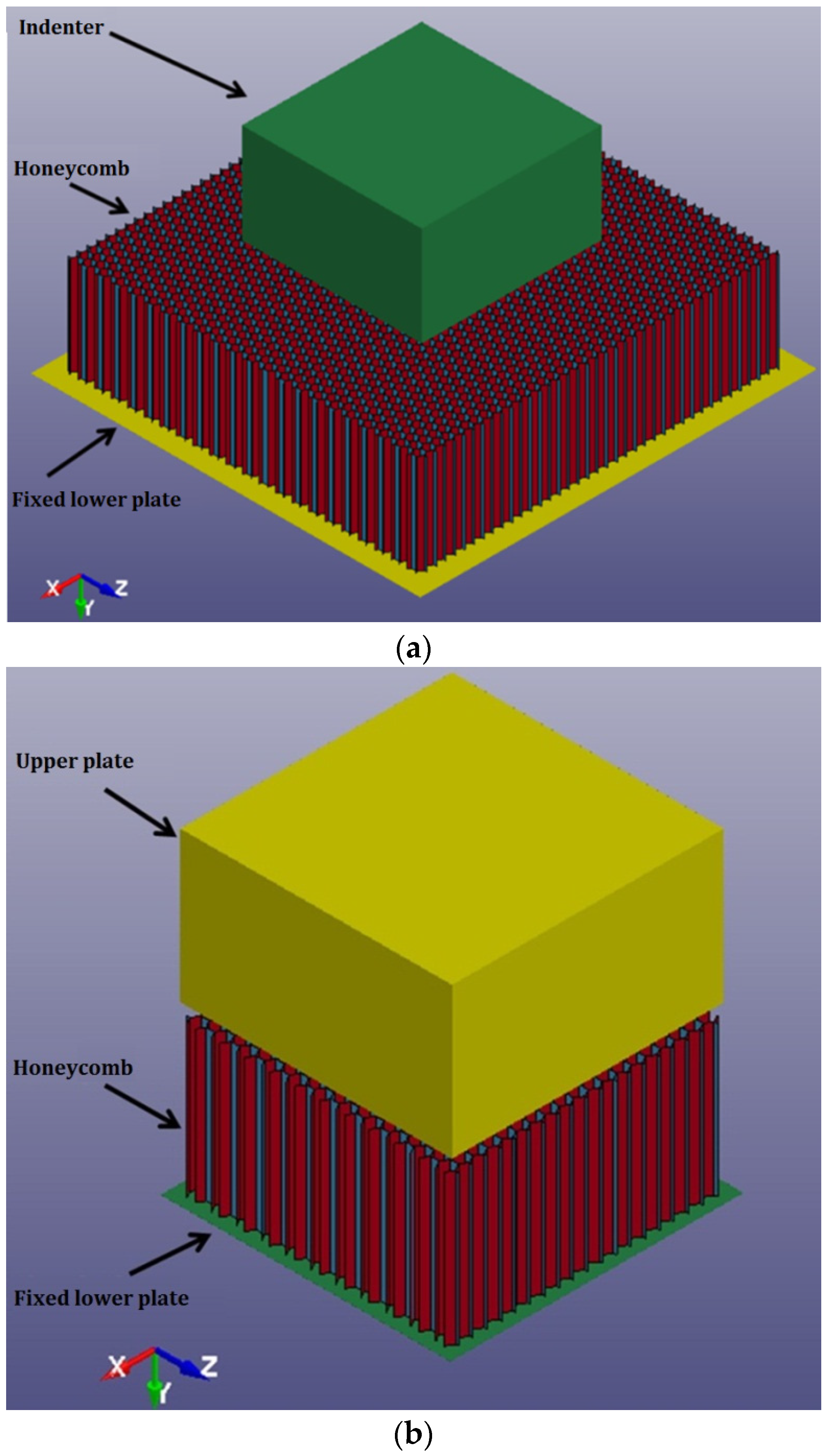
2. Finite Element (FE) Modeling
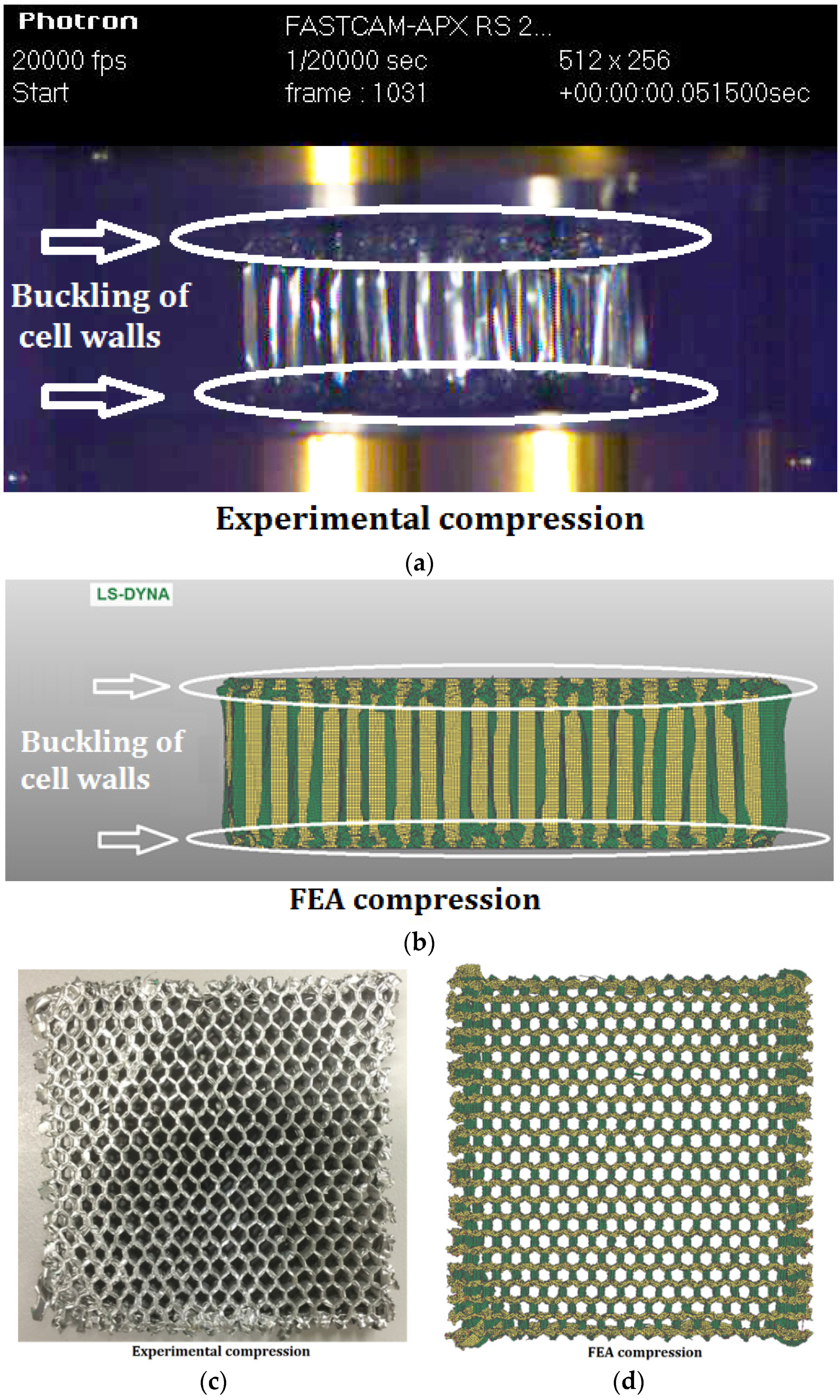
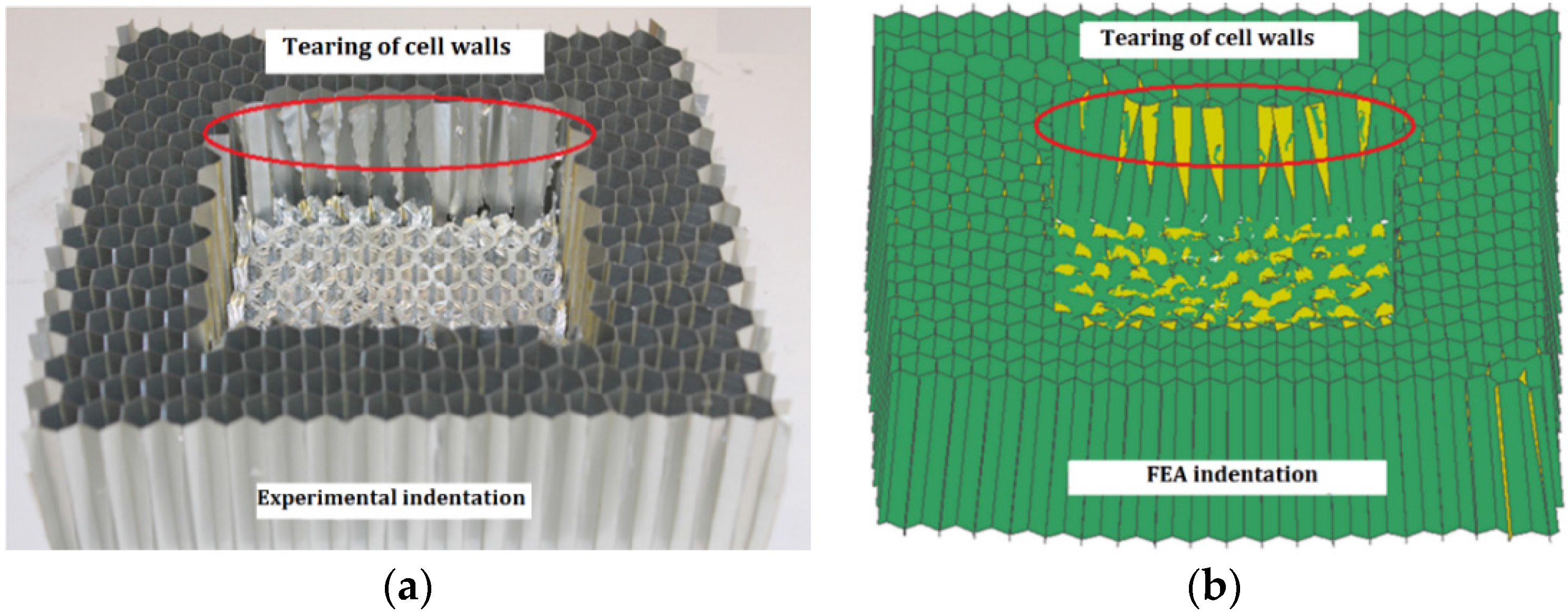
3. Validation of FE Models
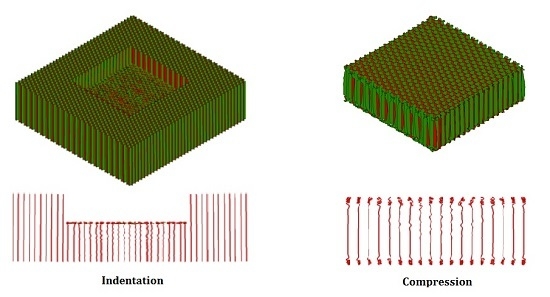
3.1. Deformation Patterns
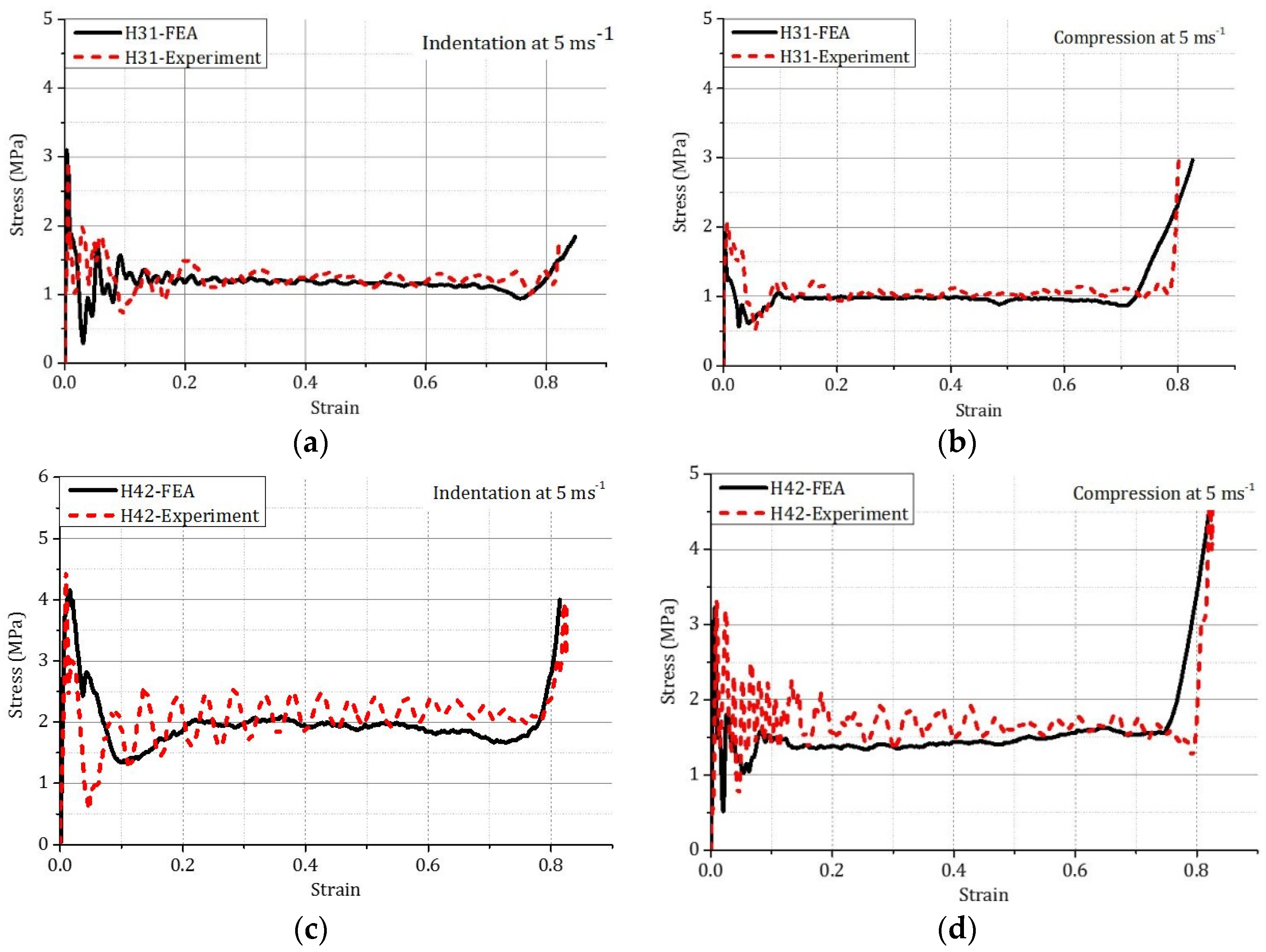
3.2. Stress-Strain Curves
4. Results and Discussion
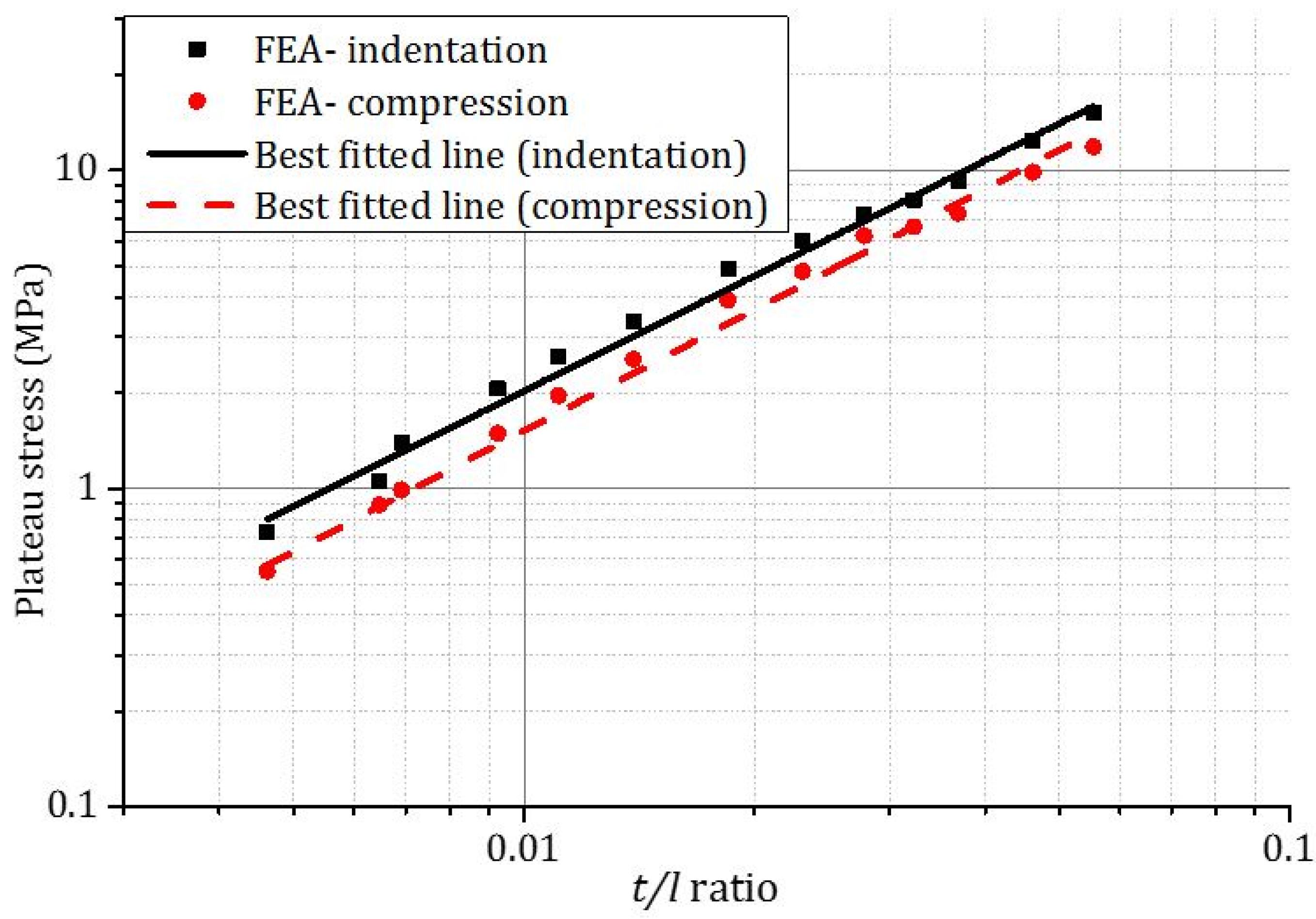
4.1. The Effect of t/l Ratio
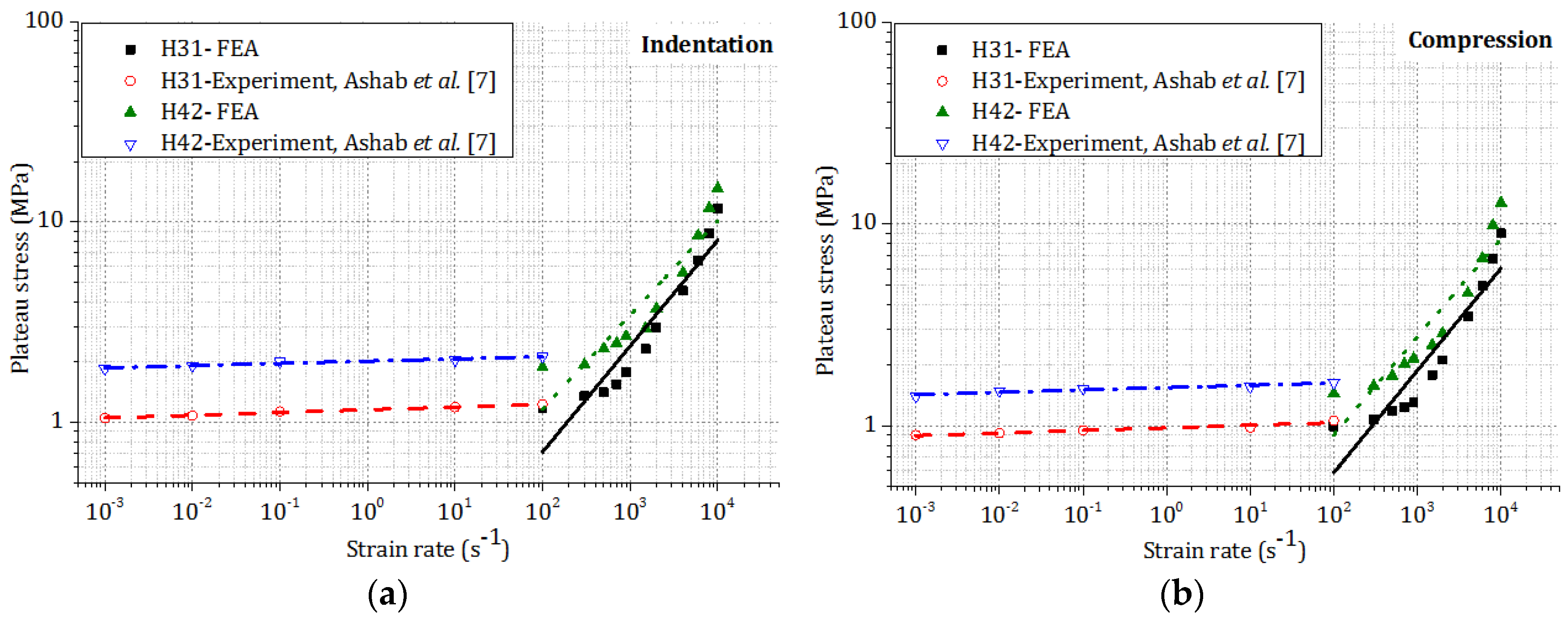
4.2. The Effect of Strain Rate,
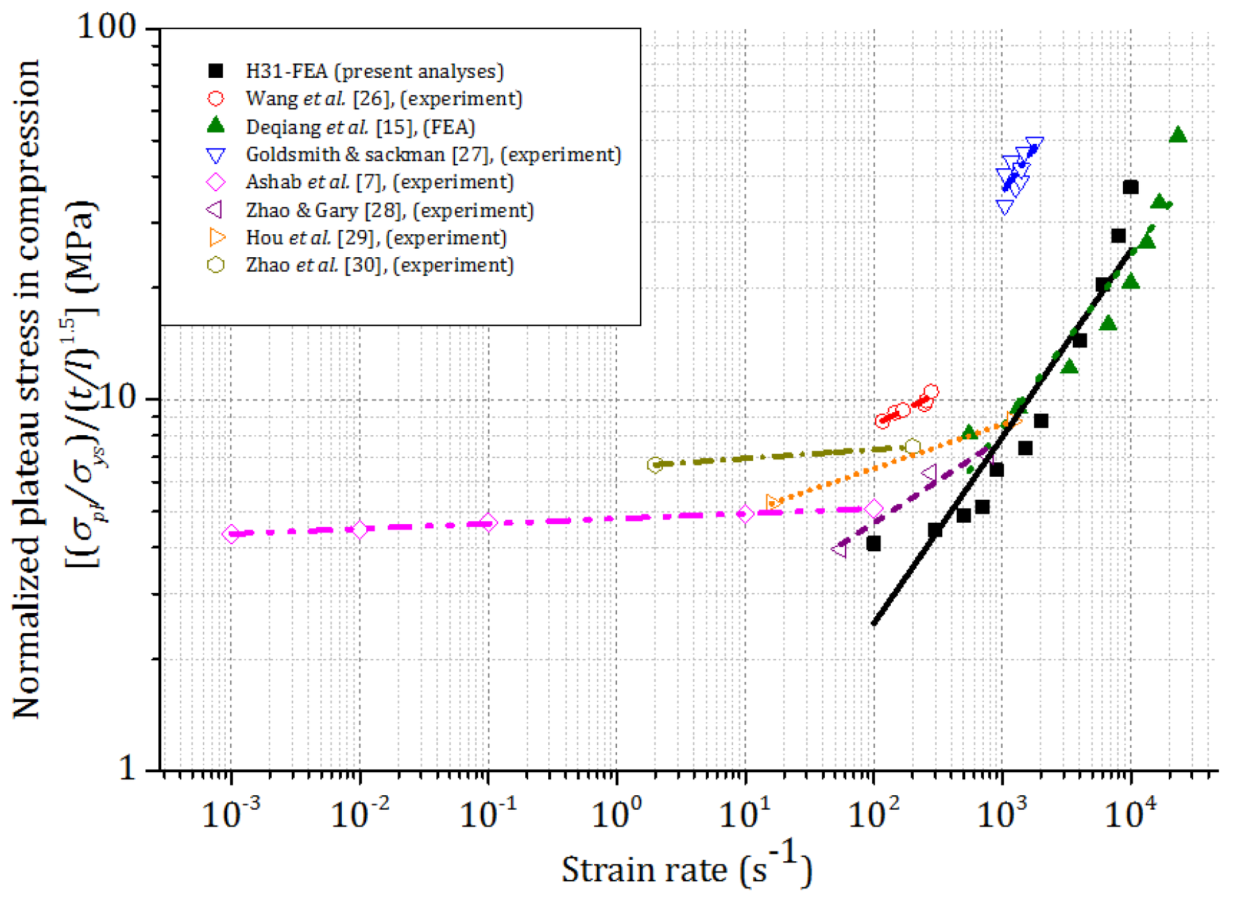
4.2.1. Plateau Stress
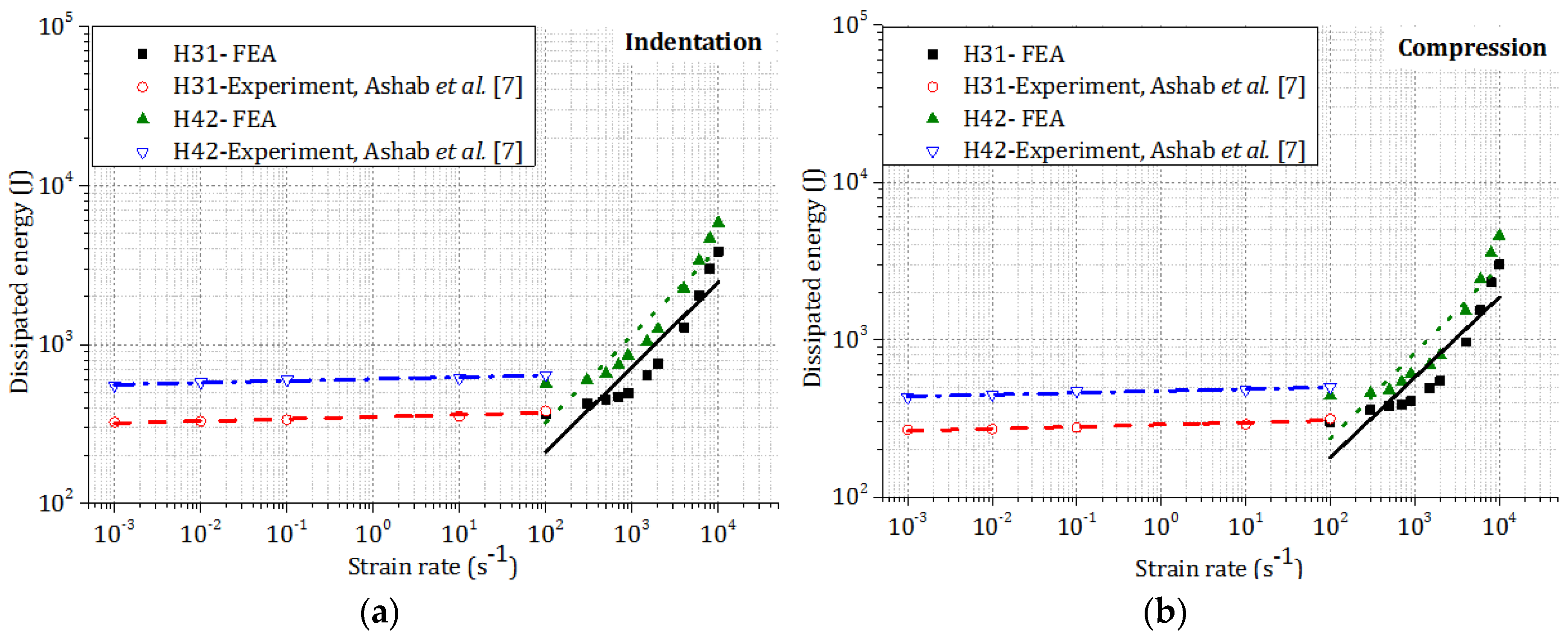
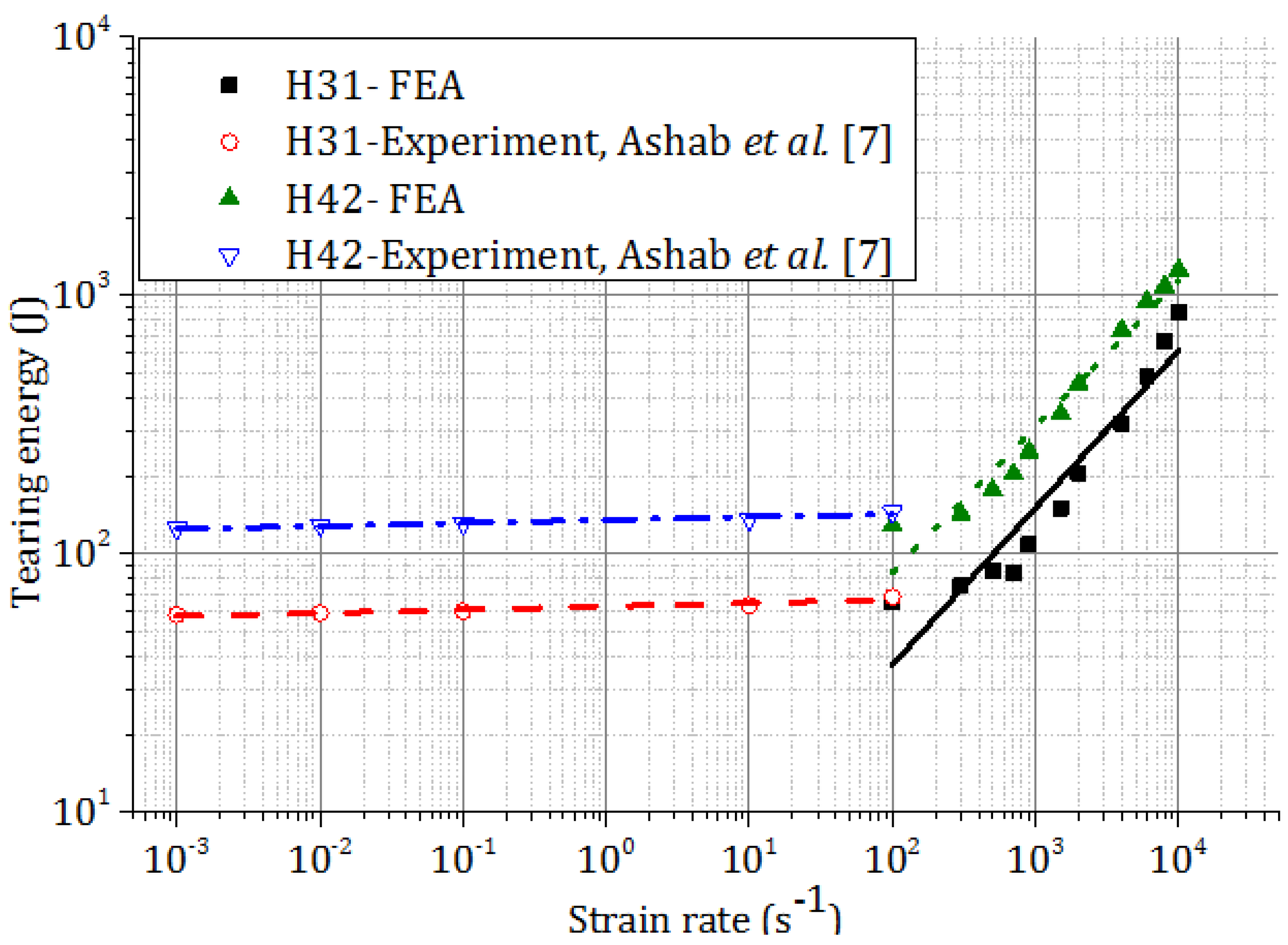
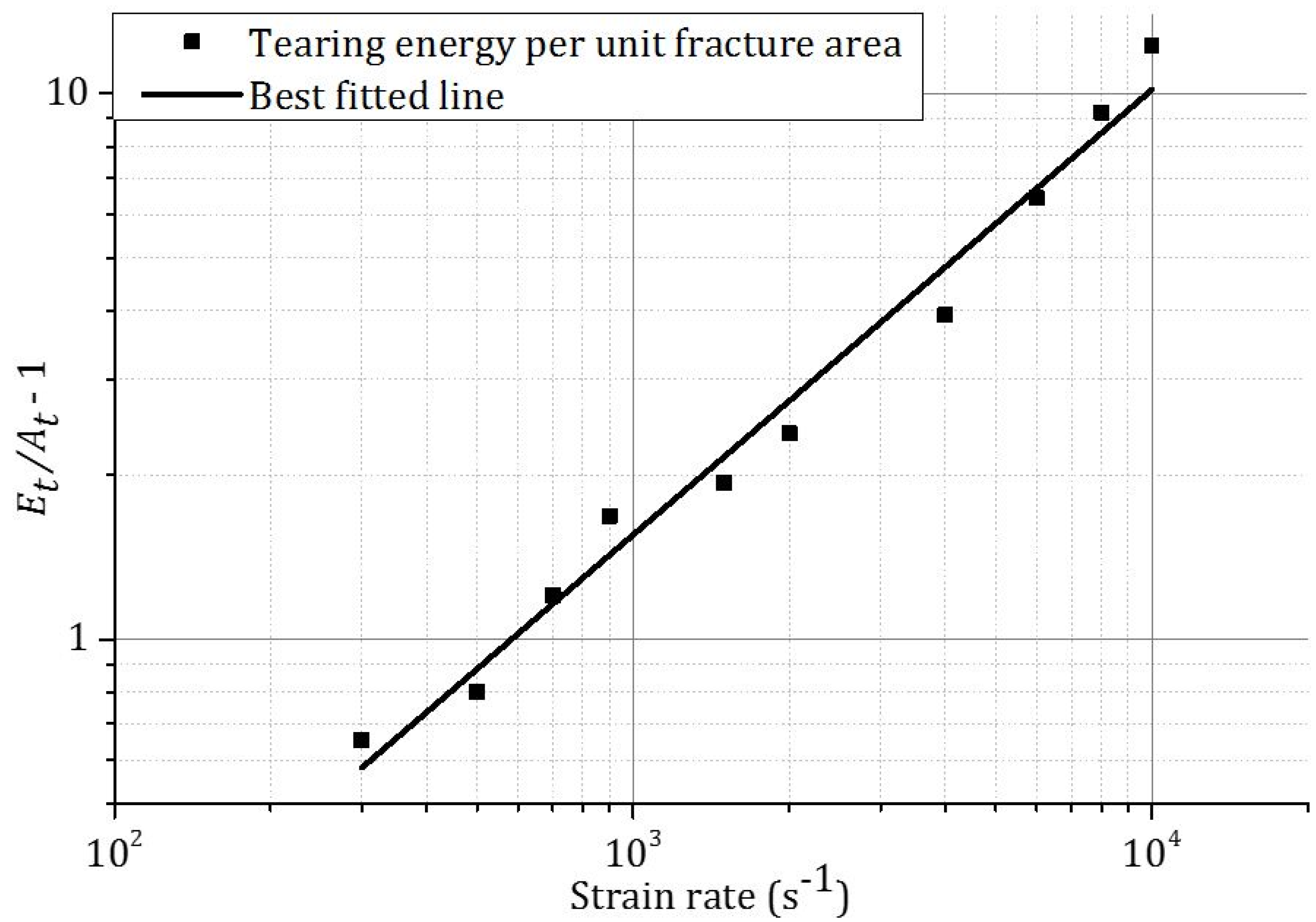
4.2.2. Energy Dissipation
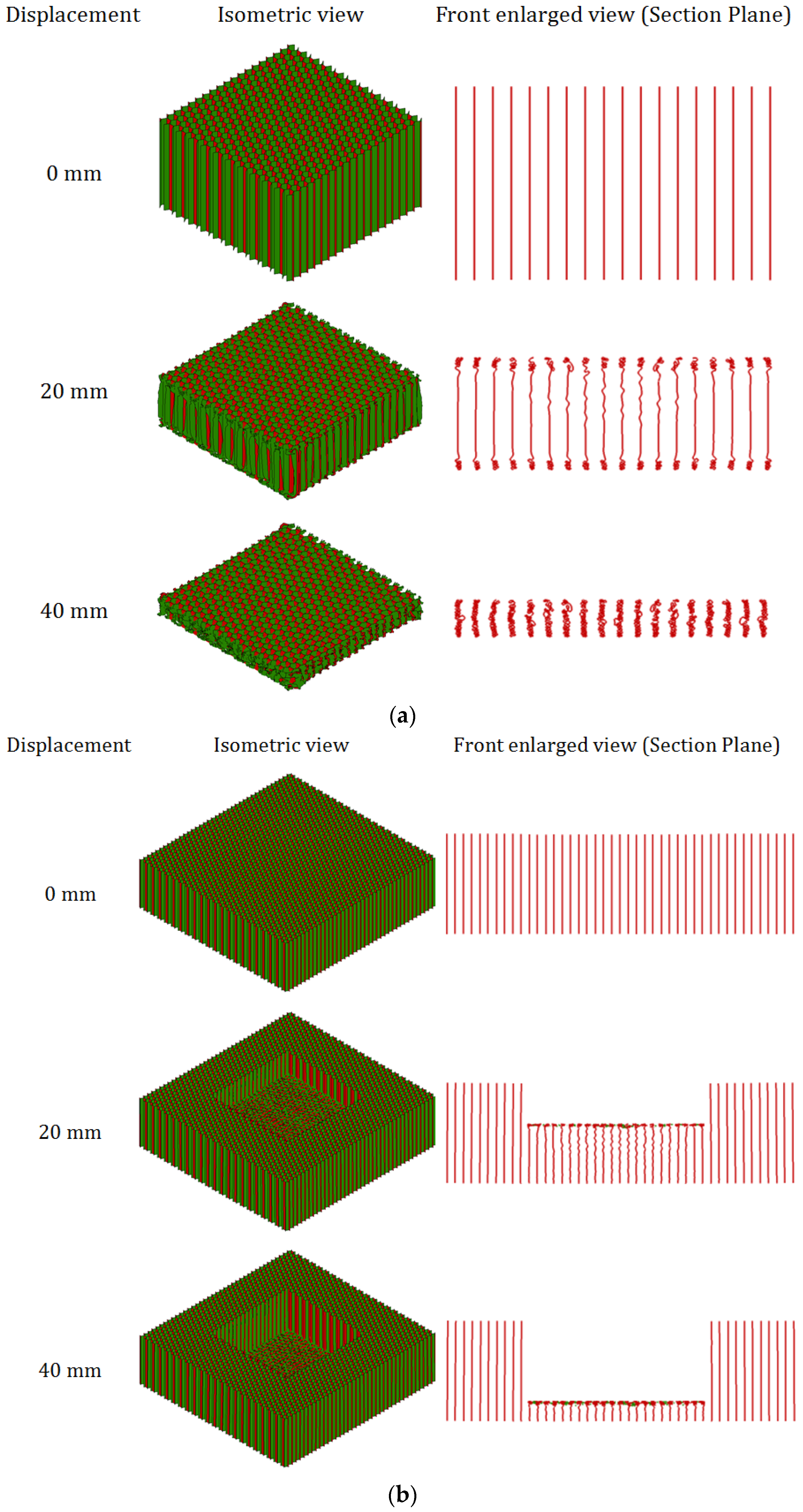
4.3. Deformation Pattern of Aluminum Honeycombs Subjected to Compression and Indentation
5. Conclusions
Acknowledgments
Author Contributions
Conflicts of Interest
References
- Versatile Flooring Panel Suitable for Passenger Cargo Compartment. The Grill Corporation. Available online: http://www.thegillcorp.com/public/mcg_msds/datasheets/Gillfloor_5424_Panel.pdf (accessed on 28 February 2015).
- koenigsegg. Agera, Specification, Chassis, Optimal Weight Distribution and Safety Chassis. Available online: http://www.Koenigsegg.Com/models/agera/ (accessed on 18 September 2014).
- Zhou, Q.; Mayer, R.R. Characterization of aluminum honeycomb material failure in large deformation compression, shear, and tearing. J. Eng. Mater. Technol. 2002, 124, 412–420. [Google Scholar] [CrossRef]
- Wu, E.; Jiang, W.S. Axial crush of metallic honeycombs. Int. J. Impact Eng. 1997, 19, 439–456. [Google Scholar] [CrossRef]
- Baker, W.E.; Togami, T.C.; Weydert, J.C. Static and dynamic properties of high-density metal honeycombs. Int. J. Impact Eng. 1998, 21, 149–163. [Google Scholar] [CrossRef]
- Xu, S.; Beynon, J.H.; Ruan, D.; Lu, G. Experimental study of the out-of-plane dynamic compression of hexagonal honeycombs. Compos. Struct. 2012, 94, 2326–2336. [Google Scholar] [CrossRef]
- Ashab, A.; Ruan, D.; Lu, G.; Xu, S.; Wen, C. Experimental investigation of the mechanical behavior of aluminum honeycombs under quasi-static and dynamic indentation. Mater. Des. 2015, 74, 138–149. [Google Scholar] [CrossRef]
- Vijayasimha Reddy, B.G.; Sharma, K.V.; Yella Reddy, T. Deformation and impact energy absorption of cellular sandwich panels. Mater. Des. 2014, 61, 217–227. [Google Scholar] [CrossRef]
- Alavi Nia, A.; Sadeghi, M.Z. An experimental investigation on the effect of strain rate on the behaviour of bare and foam-filled aluminium honeycombs. Mater. Des. 2013, 52, 748–756. [Google Scholar] [CrossRef]
- Mozafari, H.; Khatami, S.; Molatefi, H. Out of plane crushing and local stiffness determination of proposed foam filled sandwich panel for korean tilting train express—Numerical study. Mater. Des. 2015, 66, 400–411. [Google Scholar] [CrossRef]
- Guo, X.E.; Gibson, L.J. Behavior of intact and damaged honeycombs: A finite element study. Int. J. Mech. Sci. 1999, 41, 85–105. [Google Scholar] [CrossRef]
- Ruan, D.; Lu, G.; Wang, B.; Yu, T.X. In-plane dynamic crushing of honeycombs—A finite element study. Int. J. Impact Eng. 2003, 28, 161–182. [Google Scholar] [CrossRef]
- Hu, L.; You, F.; Yu, T. Analyses on the dynamic strength of honeycombs under the y-directional crushing. Mater. Des. 2014, 53, 293–301. [Google Scholar] [CrossRef]
- Hu, L.; You, F.; Yu, T. Effect of cell-wall angle on the in-plane crushing behaviour of hexagonal honeycombs. Mater. Des. 2013, 46, 511–523. [Google Scholar] [CrossRef]
- Deqiang, S.; Weihong, Z.; Yanbin, W. Mean out-of-plane dynamic plateau stresses of hexagonal honeycomb cores under impact loadings. Compos. Struct. 2010, 92, 2609–2621. [Google Scholar] [CrossRef]
- ANSYS 15—Mechanical User's Guide; Version No 15; ANSYS, Inc.: Canonsburg, PA, USA, 2013.
- Yamashita, M.; Gotoh, M. Impact behavior of honeycomb structures with various cell specifications—Numerical simulation and experiment. Int. J. Impact Eng. 2005, 32, 618–630. [Google Scholar] [CrossRef]
- Wierzbicki, T. Crushing analysis of metal honeycombs. Int. J. Impact Eng. 1983, 1, 157–174. [Google Scholar] [CrossRef]
- Xu, S.; Ruan, D.; Beynon, J.H. Finite element analysis of the dynamic behavior of aluminum honeycombs. Int. J. Comput. Methods 2014, 11. [Google Scholar] [CrossRef]
- HexWeb. Available online: http://www.hexcel.com/products/industries/ihoneycomb (accessed on 30 June 2015).
- Ju, J.; Summers, J.D.; Ziegert, J.; Fadel, G. Design of honeycomb meta-materials for high shear flexure. Proc. ASME Des. Eng. Tech. Conf. 2009, 5, 805–813. [Google Scholar]
- Shi, X.; Li, Y.; Lu, G.; Shen, C. A testing method for tearing energy of aluminum foams. Mater. Sci. Eng. A 2014, 614, 284–290. [Google Scholar] [CrossRef]
- Olurin, O.B.; Fleck, N.A.; Ashby, M.F. Indentation resistance of an aluminium foam. Scripta Mater. 2000, 43, 983–989. [Google Scholar] [CrossRef]
- Olurin, O.B.; Fleck, N.A.; Ashby, M.F. Deformation and fracture of aluminium foams. Mater. Sci. Eng. A 2000, 291, 136–146. [Google Scholar] [CrossRef]
- Zhao, H.; Abdennadher, S. On the strength enhancement under impact loading of square tubes made from rate insensitive metals. Int. J. Solids Struct. 2004, 41, 6677–6697. [Google Scholar] [CrossRef]
- Wang, Z.; Tian, H.; Lu, Z.; Zhou, W. High-speed axial impact of aluminum honeycomb—Experiments and simulations. Compos. Part B Eng. 2014, 56, 1–8. [Google Scholar] [CrossRef]
- Goldsmith, W.; Sackman, J.L. An experimental study of energy absorption in impact on sandwich plates. Int. J. Impact Eng. 1992, 12, 241–262. [Google Scholar] [CrossRef]
- Zhao, H.; Gary, G. Crushing behaviour of aluminium honeycombs under impact loading. Int. J. Impact Eng. 1998, 21, 827–836. [Google Scholar] [CrossRef]
- Hou, B.; Zhao, H.; Li, Y. Impact enhancement of the out-of-plane behaviour of honeycombs. Mater. Res. Innovations 2011, 15, s209–s212. [Google Scholar] [CrossRef]
- Zhao, H.; Elnasri, I.; Abdennadher, S. An experimental study on the behaviour under impact loading of metallic cellular materials. Int. J. Mech. Sci. 2005, 47, 757–774. [Google Scholar] [CrossRef]
- Ls-Prepost. Available online: http://www.Lstc.Com/download (accessed on 30 June 2013).


| Type | Material Description * | Cell Size, D (mm) | Single Cell Wall Thickness, t (mm) | Cell Wall Thickness to Edge Length Ratio, t/l |
|---|---|---|---|---|
| H31 | 3.1-3/16-5052-0.001N | 4.763 | 0.0254 | 0.00924 |
| H42 | 4.2-3/8-5052-0.003N | 9.525 | 0.0762 | 0.0139 |
| Material Properties | Mass Density (ρ) | Young’s Modulus (E) | Poisson’s Ratio (υ) | Yield Stress (σys) | Tangent Modulus (Etan) |
|---|---|---|---|---|---|
| Magnitude | 2680 kg/m3 | 69 GPa | 0.33 | 292 MPa | 690 MPa |
| Material Properties | Mass Density (ρ) | Young’s Modulus (E) | Poisson’s Ratio (υ) |
|---|---|---|---|
| Magnitude | 7830 kg/m3 | 207 GPa | 0.34 |
| Test Type | Honeycombs | Plateau Stress | Dissipated Energy | ||||
|---|---|---|---|---|---|---|---|
| Exp. | FEA | Difference | Exp. | FEA | Difference | ||
| MPa | MPa | % | J | J | % | ||
| Indentation | H31 | 1.23 | 1.17 | 4.88 | 382 | 364 | 4.71 |
| Indentation | H42 | 2.13 | 1.89 | 11.26 | 644 | 571 | 11.33 |
| Compression | H31 | 1.06 | 0.99 | 6.66 | 314 | 294 | 6.36 |
| Compression | H42 | 1.64 | 1.45 | 11.58 | 499 | 441 | 11.62 |
| Loading Type | FEA No. | Cell Size, D | Cell Wall Thickness, t | t/l Ratio | Plateau Stress | Dissipated Energy | Tearing Energy |
|---|---|---|---|---|---|---|---|
| mm | mm | - | MPa | J | J | ||
| Indentation | CS-I-1 | 3.175 | 0.0254 | 0.01388 | 3.74 | 1262 | 309 |
| CS-I-2 | 3.969 | 0.0254 | 0.01109 | 2.81 | 955 | 224 | |
| CS-I-3 | 4.763 | 0.0254 | 0.00924 | 2.18 | 731 | 183 | |
| CS-I-4 | 6.35 | 0.0254 | 0.00692 | 1.39 | 472 | 153 | |
| CS-I-5 | 9.525 | 0.0254 | 0.00462 | 0.73 | 256 | 78 | |
| Compression | CS-C-1 | 3.175 | 0.0254 | 0.01388 | 2.95 | 953 | - |
| CS-C-2 | 3.969 | 0.0254 | 0.01109 | 2.26 | 731 | - | |
| CS-C-3 | 4.763 | 0.0254 | 0.00924 | 1.69 | 548 | - | |
| CS-C-4 | 6.35 | 0.0254 | 0.00692 | 0.99 | 319 | - | |
| CS-C-5 | 9.525 | 0.0254 | 0.00462 | 0.55 | 178 | - |
| Loading Type | FEA No. | Cell Wall Thickness, t | t/l Ratio | Plateau Stress | Dissipated Energy | Tearing Energy |
|---|---|---|---|---|---|---|
| mm | - | MPa | J | J | ||
| Indentation | TL-I-1 | 0.0178 | 0.00647 | 1.05 | 378 | 91 |
| TL-I-2 | 0.0254 | 0.00924 | 2.16 | 727 | 187 | |
| TL-I-3 | 0.0381 | 0.01386 | 3.72 | 1260 | 315 | |
| TL-I-4 | 0.0508 | 0.01847 | 4.91 | 1642 | 387 | |
| TL-I-5 | 0.0635 | 0.02309 | 5.98 | 2005 | 449 | |
| TL-I-6 | 0.0762 | 0.02771 | 7.24 | 2415 | 526 | |
| TL-I-7 | 0.0889 | 0.03233 | 8.09 | 2695 | 678 | |
| TL-I-8 | 0.1016 | 0.03695 | 9.21 | 3082 | 829 | |
| TL-I-9 | 0.127 | 0.04618 | 11.39 | 3823 | 1064 | |
| TL-I-10 | 0.1524 | 0.05542 | 13.24 | 4451 | 1370 | |
| Compression | TL-C-1 | 0.0178 | 0.00647 | 0.89 | 287 | - |
| TL-C-2 | 0.0254 | 0.00924 | 1.66 | 540 | - | |
| TL-C-3 | 0.0381 | 0.01386 | 2.93 | 945 | - | |
| TL-C-4 | 0.0508 | 0.01847 | 3.91 | 1255 | - | |
| TL-C-5 | 0.0635 | 0.02309 | 4.82 | 1556 | - | |
| TL-C-6 | 0.0762 | 0.02771 | 6.24 | 1889 | - | |
| TL-C-7 | 0.0889 | 0.03233 | 6.65 | 2017 | - | |
| TL-C-8 | 0.1016 | 0.03695 | 7.34 | 2253 | - | |
| TL-C-9 | 0.127 | 0.04618 | 8.86 | 2759 | - | |
| TL-C-10 | 0.1524 | 0.05542 | 9.86 | 3081 | - |
© 2016 by the authors; licensee MDPI, Basel, Switzerland. This article is an open access article distributed under the terms and conditions of the Creative Commons by Attribution (CC-BY) license (http://creativecommons.org/licenses/by/4.0/).
Share and Cite
Ashab, A.S.M.A.; Ruan, D.; Lu, G.; Bhuiyan, A.A. Finite Element Analysis of Aluminum Honeycombs Subjected to Dynamic Indentation and Compression Loads. Materials 2016, 9, 162. https://doi.org/10.3390/ma9030162
Ashab ASMA, Ruan D, Lu G, Bhuiyan AA. Finite Element Analysis of Aluminum Honeycombs Subjected to Dynamic Indentation and Compression Loads. Materials. 2016; 9(3):162. https://doi.org/10.3390/ma9030162
Chicago/Turabian StyleAshab, A.S.M. Ayman, Dong Ruan, Guoxing Lu, and Arafat A. Bhuiyan. 2016. "Finite Element Analysis of Aluminum Honeycombs Subjected to Dynamic Indentation and Compression Loads" Materials 9, no. 3: 162. https://doi.org/10.3390/ma9030162
APA StyleAshab, A. S. M. A., Ruan, D., Lu, G., & Bhuiyan, A. A. (2016). Finite Element Analysis of Aluminum Honeycombs Subjected to Dynamic Indentation and Compression Loads. Materials, 9(3), 162. https://doi.org/10.3390/ma9030162