
Surface Characterizations of Fretting Fatigue Damage in Aluminum Alloy 7075-T6 Clamped Joints: The Beneficial Role of Ni–P Coatings


Abstract
:1. Introduction
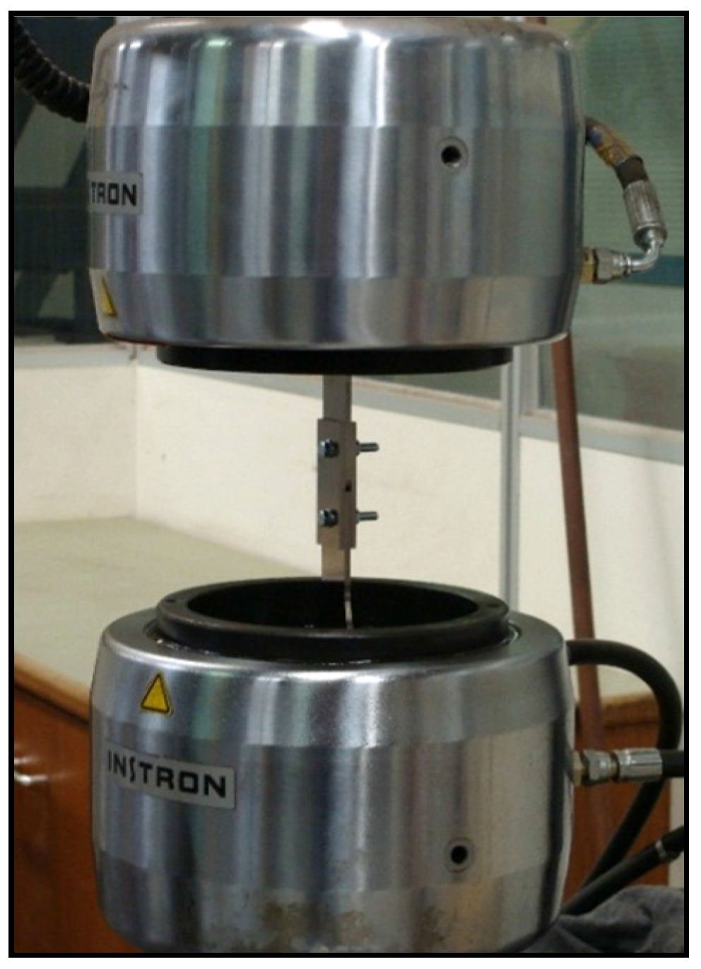
2. Experimental Details
3. Results and Discussion
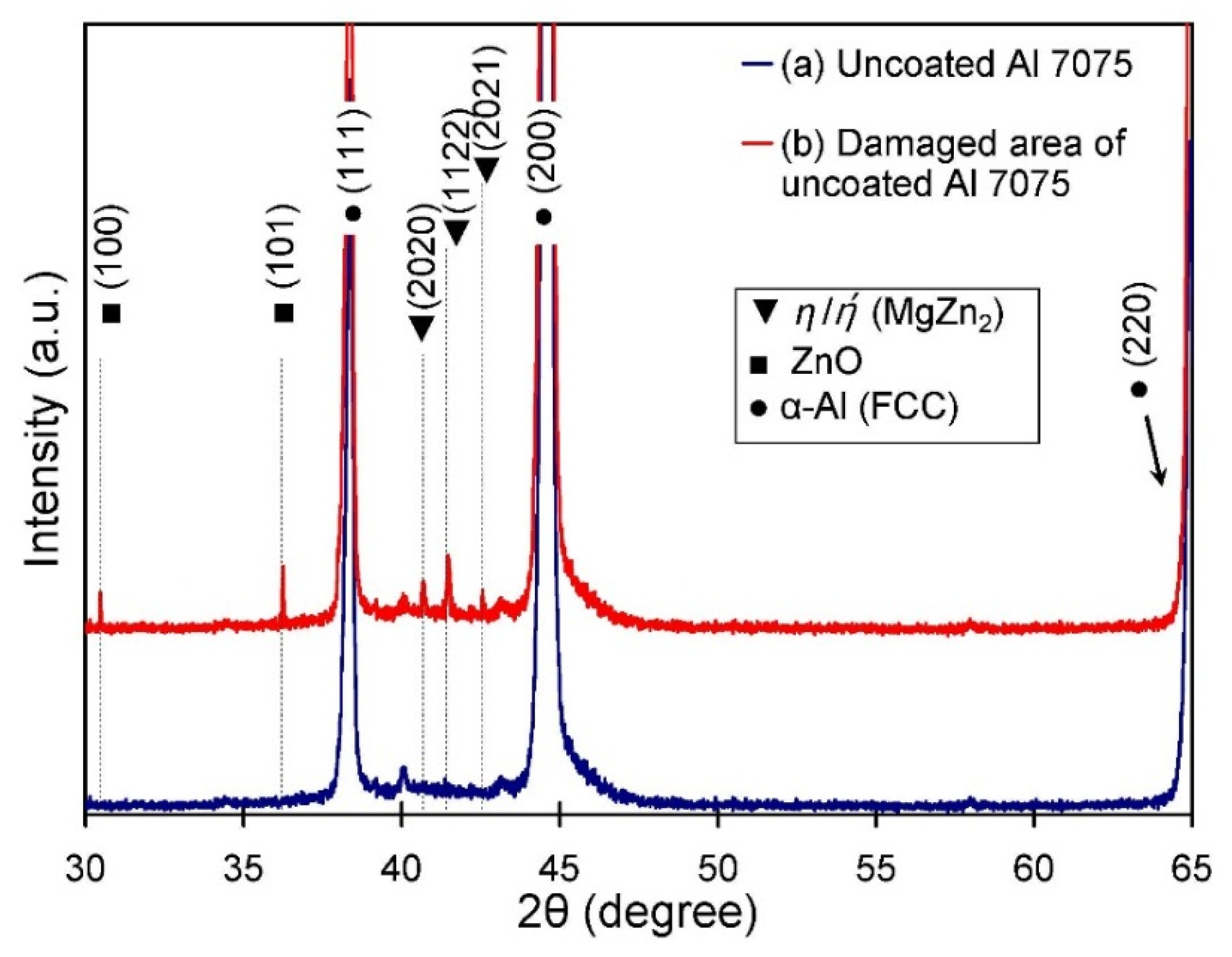
3.1. XRD Analysis of Uncoated Al 7075-T6
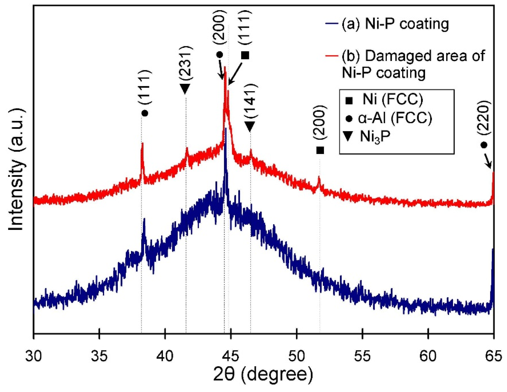
3.2. XRD Analysis of Coated Al 7075-T6
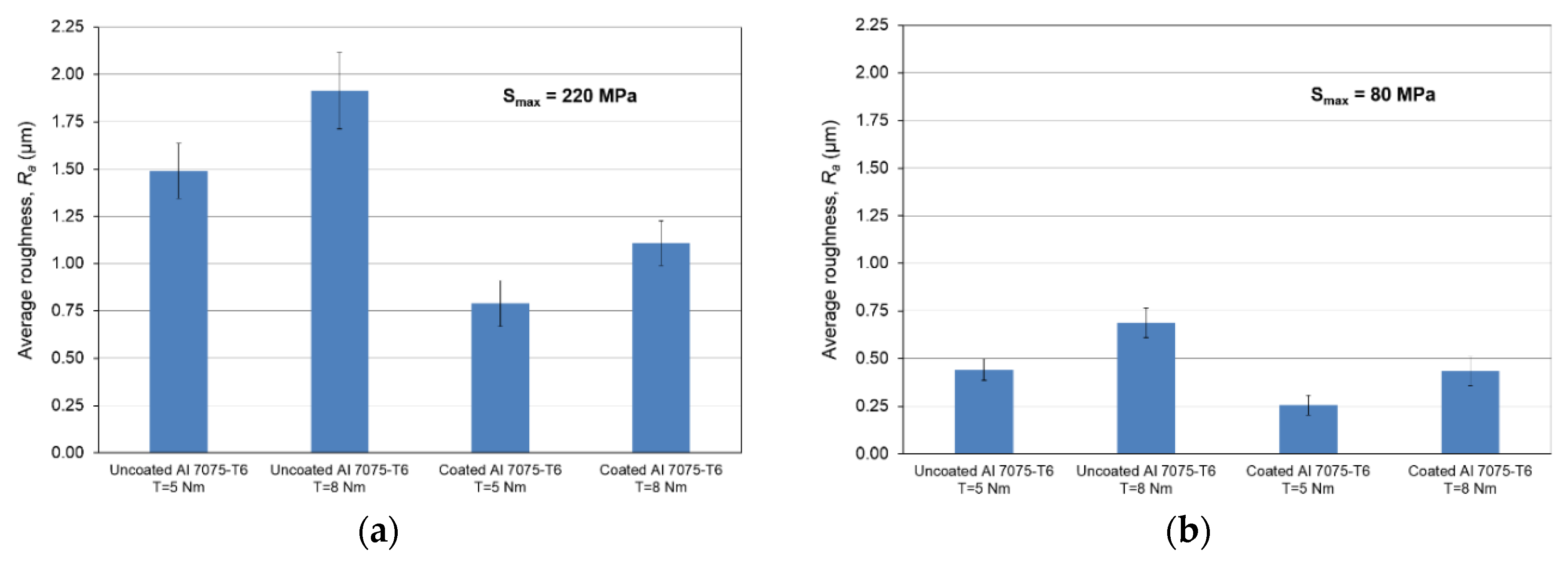
3.3. Surface Profilometry
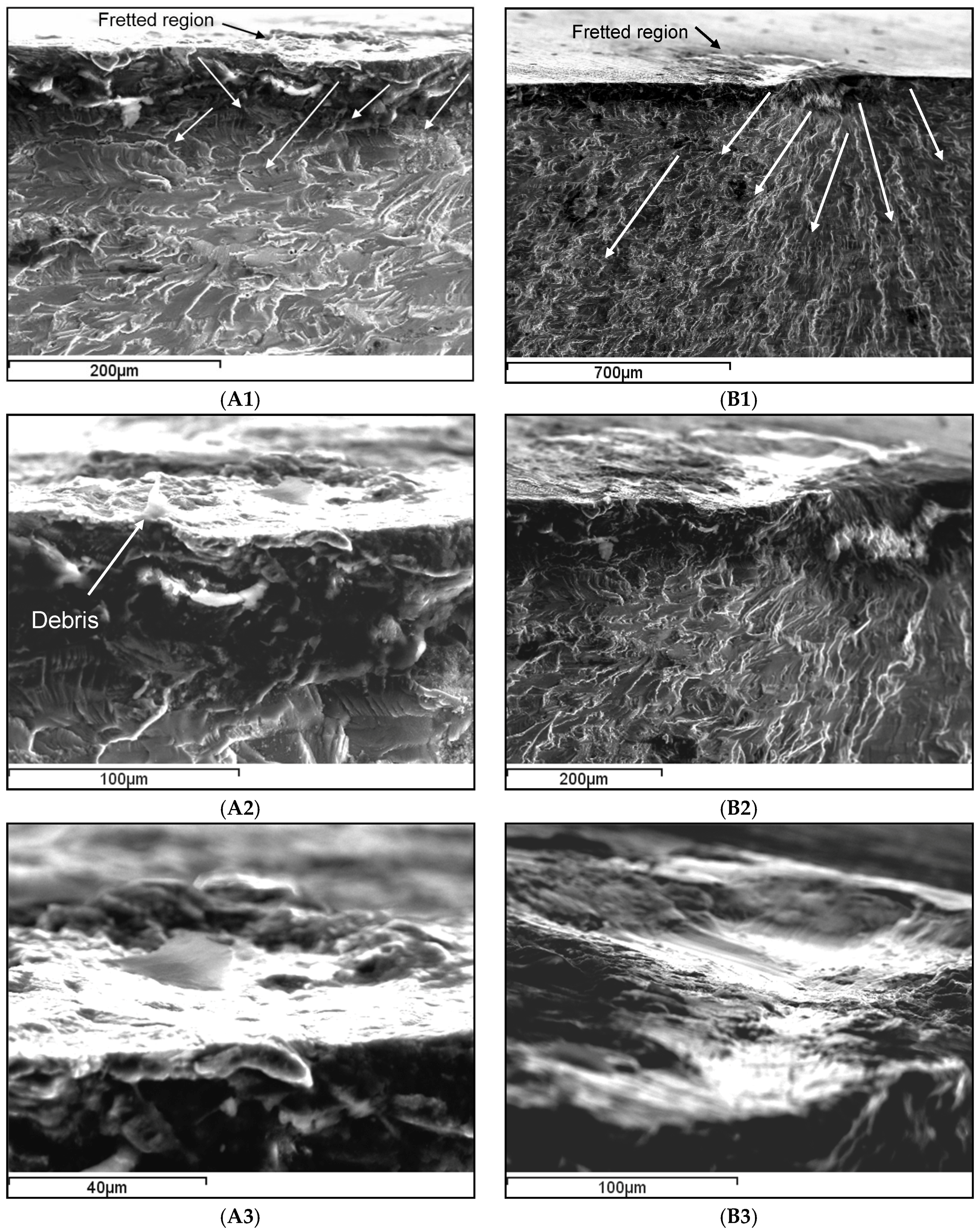
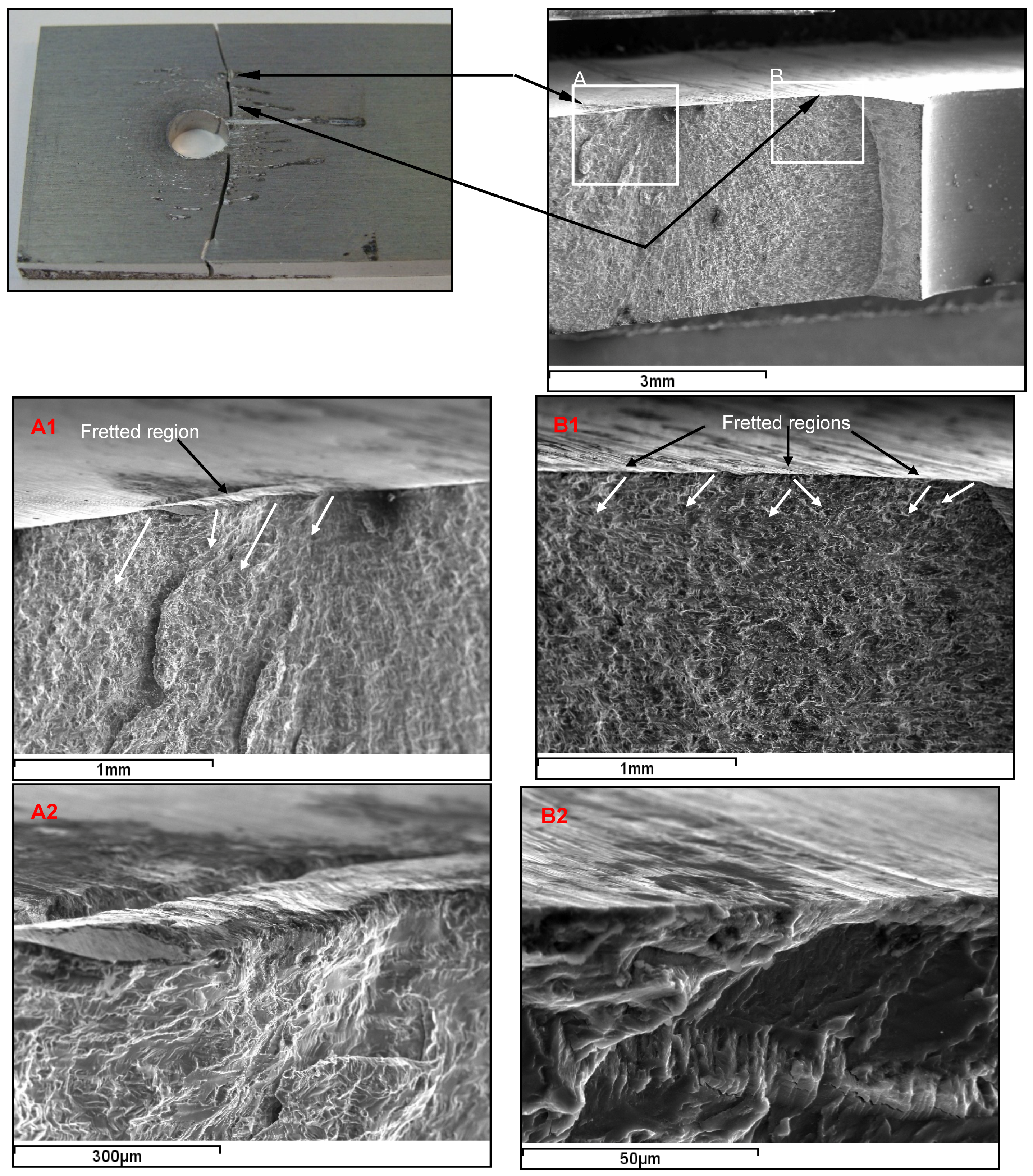
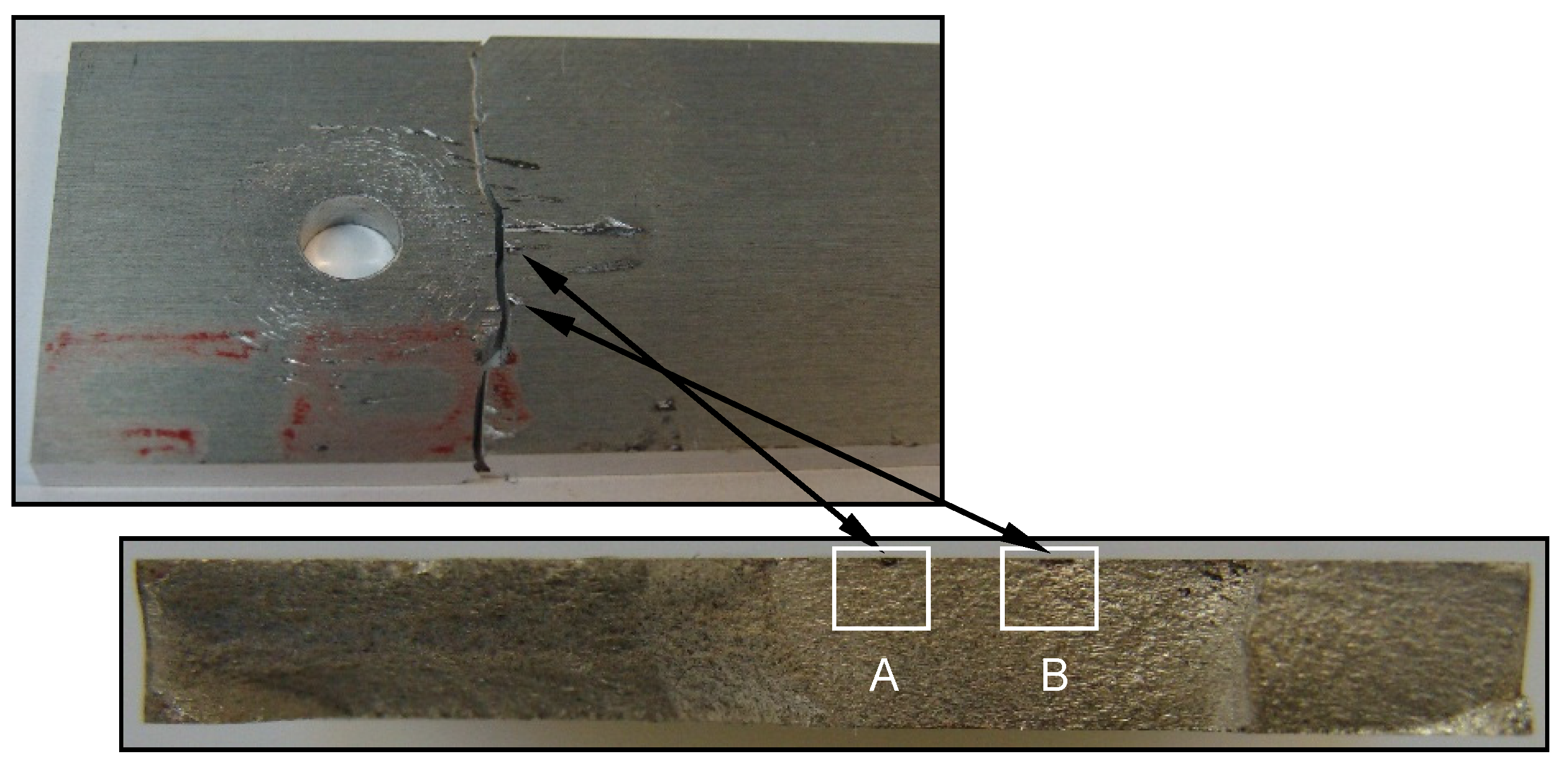
3.4. SEM Examinations
4. Conclusions
Acknowledgments
Author Contributions
Conflicts of Interest
References
- Szolwinski, M.P.; Farris, T.N. Mechanics of fretting fatigue crack formation. Wear 1996, 198, 93–107. [Google Scholar] [CrossRef]
- Shaffer, S.J.; Glaeser, W.A. Fretting Fatigue Testing, ASM Handbook, Vol. 8, Mechanical Testing and Evaluation; ASM International: Materials Park, OH, USA, 2000. [Google Scholar]
- Chakherloua, T.N.; Shakouri, M.; Akbari, A.; Aghdam, A.B. Effect of cold expansion and bolt clamping on fretting fatigue behavior of Al 2024-T3 in double shear lap joints. Eng. Fail. Anal. 2012, 25, 29–41. [Google Scholar] [CrossRef]
- Oskouei, R.H.; Ibrahim, R.N. Improving fretting fatigue behaviour of Al 7075-T6 bolted plates using electroless Ni–P coatings. Int. J. Fatigue 2012, 44, 157–167. [Google Scholar] [CrossRef]
- Fallahnezhad, K.; Steele, A.; Oskouei, R.H. Failure mode analysis of aluminium alloy 2024-T3 in double-lap bolted joints with single and double fasteners; a numerical and experimental study. Materials 2015, 8, 3195–3209. [Google Scholar] [CrossRef]
- Oskouei, R.H.; Keikhosravy, M.; Soutis, C. A finite element stress analysis of aircraft bolted joints loaded in tension. Raes 2010, 114, 315–320. [Google Scholar] [CrossRef]
- Keikhosravy, M.; Oskouei, R.H.; Soltani, P.; Atas, A.; Soutis, C. Effect of geometric parameters on the stress distribution in Al 2024-T3 single-lap bolted joints. Int. J. Struct. Integr. 2012, 3, 79–93. [Google Scholar] [CrossRef]
- Oskouei, R.H.; Ibrahim, R.N. The effect of clamping compressive stresses on the fatigue life of Al 7075-T6 bolted plates at different temperatures. Mater. Des. 2012, 34, 90–97. [Google Scholar] [CrossRef]
- Chakherlou, T.N.; Oskouei, R.H.; Vogwell, J. Experimental and numerical investigation of the effect of clamping force on the fatigue behaviour of bolted plates. Eng. Fail. Anal. 2008, 15, 563–574. [Google Scholar] [CrossRef]
- Benhamena, A.; Talha, A.; Benseddiq, N.; Amrouche, A.; Mesmacque, G.; Benguediab, M. Effect of clamping force on fretting fatigue behaviour of bolted assemblies: Case of couple steel–aluminium. Mater. Sci. Eng. A 2010, 527, 6413–6421. [Google Scholar] [CrossRef]
- Chakherlou, T.N.; Razavi, M.J.; Aghdam, A.B.; Abazadeh, B. An experimental investigation of the bolt clamping force and friction effect on the fatigue behavior of aluminum alloy 2024-T3 double shear lap joint. Mater. Des. 2011, 32, 4641–4649. [Google Scholar] [CrossRef]
- Shinde, S.R.; Hoeppner, D.W. Fretting fatigue behavior in 7075-T6 aluminum alloy. Wear 2006, 261, 426–434. [Google Scholar] [CrossRef]
- Jin, O.; Mall, S.; Sanders, J.H.; Sharma, S.K. Durability of Cu–Al coating on Ti-6Al-4V substrate under fretting fatigue. Surf. Coat. Tech. 2006, 201, 1704–1710. [Google Scholar] [CrossRef]
- Ibrahim, R.N.; Rahmat, M.; Oskouei, R.H.; Singh, R. Monolayer TiAlN and multilayer TiAlN/CrN PVD coatings as surface modifiers to mitigate fretting fatigue of AISI P20 steel. Eng. Fract. Mech. 2015, 137, 64–78. [Google Scholar] [CrossRef]
- Majzoobi, G.H.; Nemati, J.; Novin Rooz, A.J.; Farrahi, G.H. Modification of fretting fatigue behavior of AL7075-T6 alloy by the application of titanium coating using IBED technique and shot peening. Tribol. Int. 2009, 42, 121–129. [Google Scholar] [CrossRef]
- Rahmat, M.; Ibrahim, R.N.; Oskouei, R.H. A stress-based approach to analyse fretting fatigue life behaviour of electroless Ni–P coated Al 7075-T6. Mater. Sci. Eng. A. 2015, 631, 126–138. [Google Scholar] [CrossRef]
- Mishra, A. Dry sliding wear of wrought Al-alloys. Int. J. Mech. Eng. Rob. Res. 2014, 3, 432–436. [Google Scholar]
- Prasad, B.K. Influence of some test parameters on dry sliding wear characteristics of a Zinc-11.5% aluminum alloy. Mater. Eng. Perform. 2002, 11, 461–468. [Google Scholar] [CrossRef]
- Cai, Z.; Zhu, M.; Lin, X. Friction and wear of 7075 aluminum alloy induced by torsional fretting. Trans. Nonfer. Met. Soc. China 2010, 20, 371–376. [Google Scholar] [CrossRef]
- Kang, H.B.; Jongwoo, P.; Bae, J.H.; Yang, C.W. Crystallization behaviour of electroless Ni–P UBM with medium phosphorous induced by single and step heat treatment. Mater. Trans. 2010, 51, 1878–1882. [Google Scholar] [CrossRef]
- Muthuswamy, E.; Savithra, G.H.L.; Brock, S.L. Synthetic levers enabling independent control of phase, size, and morphology in nickel phosphide nanoparticles. ACS Nano 2011, 5, 2402–2411. [Google Scholar] [CrossRef] [PubMed]
- Wang, J.; Johnston-Peck, A.C.; Tracy, J.B. Nickel phosphide nanoparticles with hollow, solid, and amorphous structures. Chem. Mater. 2009, 21, 4462–4467. [Google Scholar] [CrossRef]
- Scott, R. Physical Methods in Bioinorganic Chemistry: Spectroscopy and Magnetism; University Science Books: Herndon, VA, USA, 2000. [Google Scholar]
- Kennedy, F.E. Modern Tribology Handbook; CRC Press: Boca Raton, FL, USA, 2000. [Google Scholar]
- Shuler, S.F.; Holrnes, J.W.; Wu, X. Influence of loading frequency on the room-temperature fatigue of a carbon-fiber/SiC-matrix composite. J. Am. Ceram. Soc. 1993, 76, 2327–2336. [Google Scholar] [CrossRef]
- Oskouei, R.H.; Ibrahim, R.N. Restoring the tensile properties of PVD-TiN coated Al 7075-T6 using a post heat treatment. Surf. Coat. Tech. 2011, 205, 3967–3973. [Google Scholar] [CrossRef]


| Profiles | Uncoated Al 7075-T6 Plates | |
|---|---|---|
| T = 5 Nm | T = 8 Nm | |
| 3D surface profile | 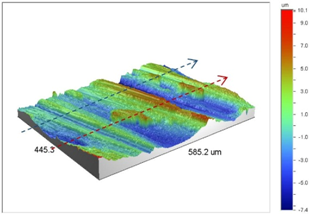 |  |
| Line scan profiles |  | 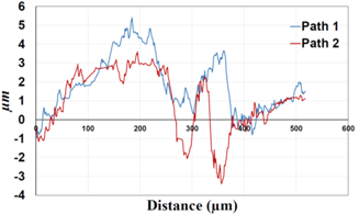 |
| Profiles | Coated Al 7075-T6 plates with Ni–P coatings | |
| T = 5 Nm | T = 8 Nm | |
| 3D surface profile | 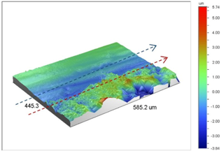 | 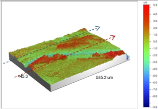 |
| Line scan profiles | 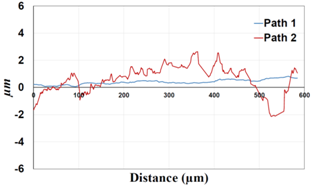 |  |
| Profiles | Uncoated Al 7075-T6 Plates | |
|---|---|---|
| T = 5 Nm | T = 8 Nm | |
| 3D surface profile | 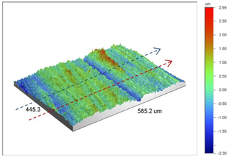 | 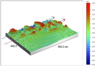 |
| Line scan profiles | 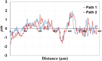 | 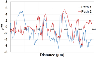 |
| Profiles | Coated Al 7075-T6 plates with Ni–P coatings | |
| T = 5 Nm | T = 8 Nm | |
| 3D surface profile | 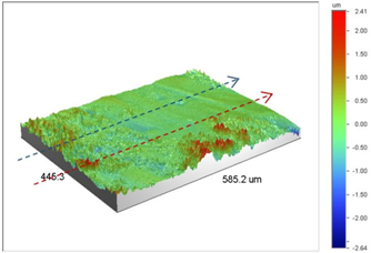 | 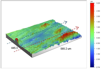 |
| Line scan profiles | 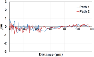 | 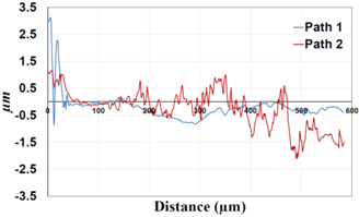 |
© 2016 by the authors; licensee MDPI, Basel, Switzerland. This article is an open access article distributed under the terms and conditions of the Creative Commons by Attribution (CC-BY) license (http://creativecommons.org/licenses/by/4.0/).
Share and Cite
Oskouei, R.H.; Barati, M.R.; Ibrahim, R.N. Surface Characterizations of Fretting Fatigue Damage in Aluminum Alloy 7075-T6 Clamped Joints: The Beneficial Role of Ni–P Coatings. Materials 2016, 9, 141. https://doi.org/10.3390/ma9030141
Oskouei RH, Barati MR, Ibrahim RN. Surface Characterizations of Fretting Fatigue Damage in Aluminum Alloy 7075-T6 Clamped Joints: The Beneficial Role of Ni–P Coatings. Materials. 2016; 9(3):141. https://doi.org/10.3390/ma9030141
Chicago/Turabian StyleOskouei, Reza H., Mohammad Reza Barati, and Raafat N. Ibrahim. 2016. "Surface Characterizations of Fretting Fatigue Damage in Aluminum Alloy 7075-T6 Clamped Joints: The Beneficial Role of Ni–P Coatings" Materials 9, no. 3: 141. https://doi.org/10.3390/ma9030141
APA StyleOskouei, R. H., Barati, M. R., & Ibrahim, R. N. (2016). Surface Characterizations of Fretting Fatigue Damage in Aluminum Alloy 7075-T6 Clamped Joints: The Beneficial Role of Ni–P Coatings. Materials, 9(3), 141. https://doi.org/10.3390/ma9030141