
Nanoindentation Characterization of a Ternary Clay-Based Composite Used in Ancient Chinese Construction

 ,
,  ,
,
Abstract
:1. Introduction
2. Materials and Methods
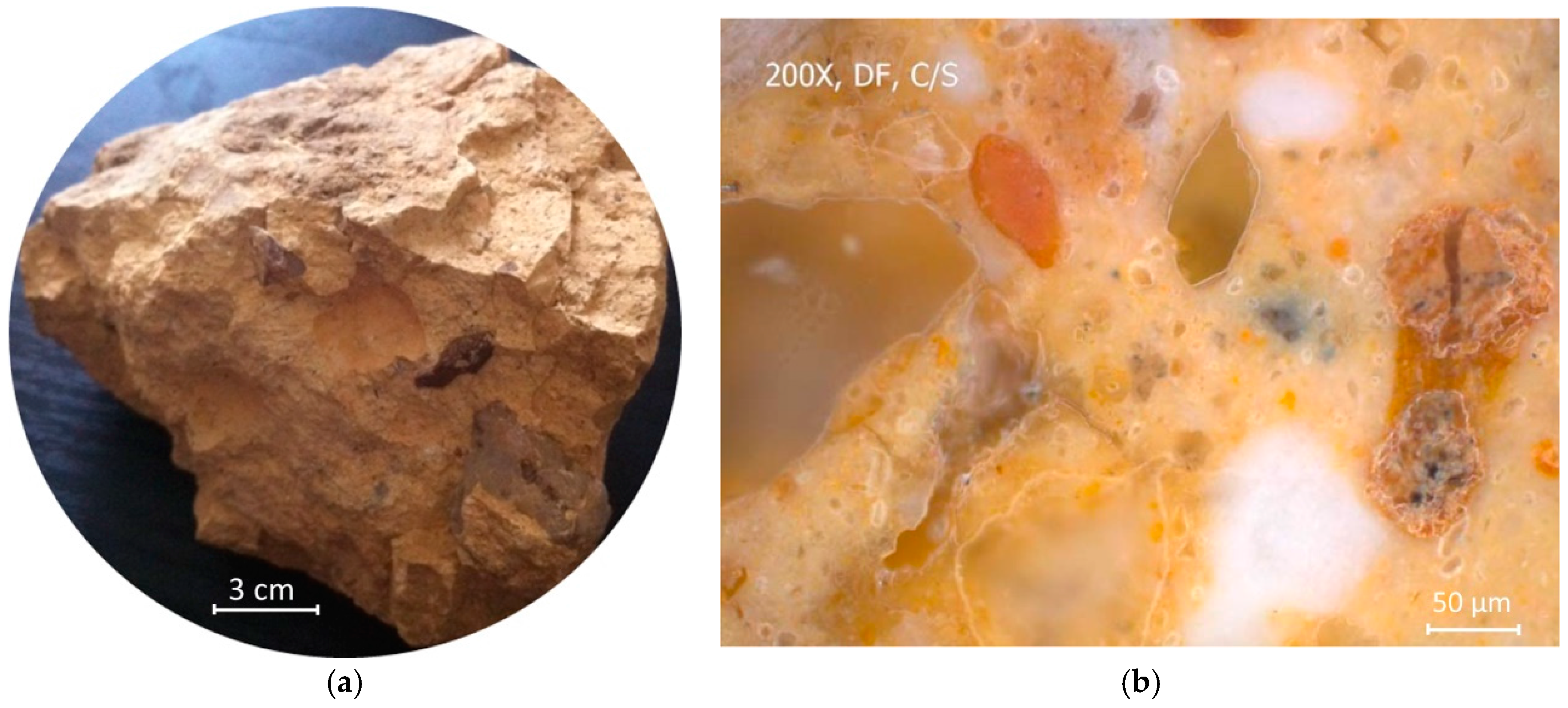
2.1. TCC Samples
2.2. X-ray Diffraction
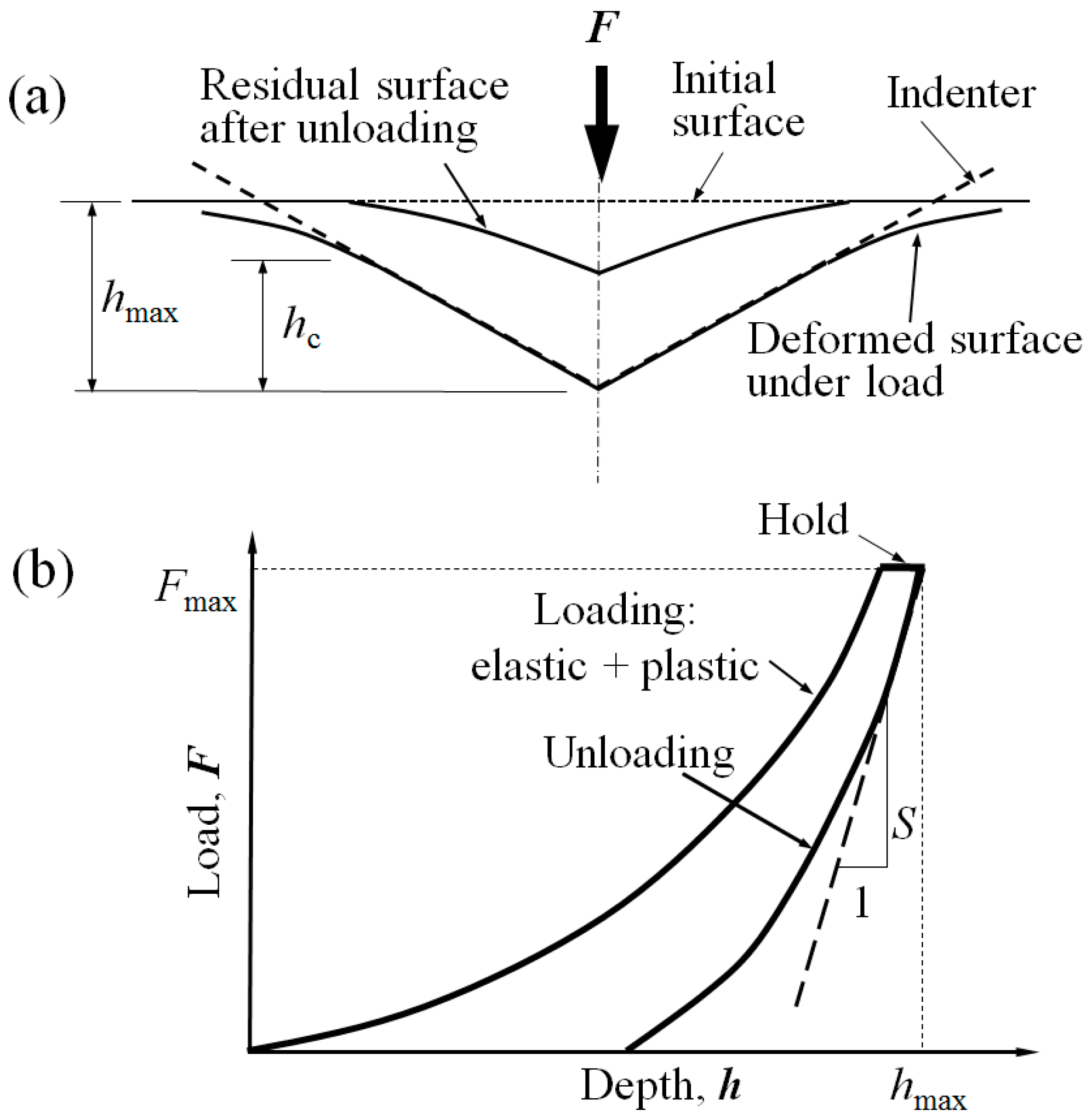
2.3. Nanoindentation Testing
3. Results and Discussion
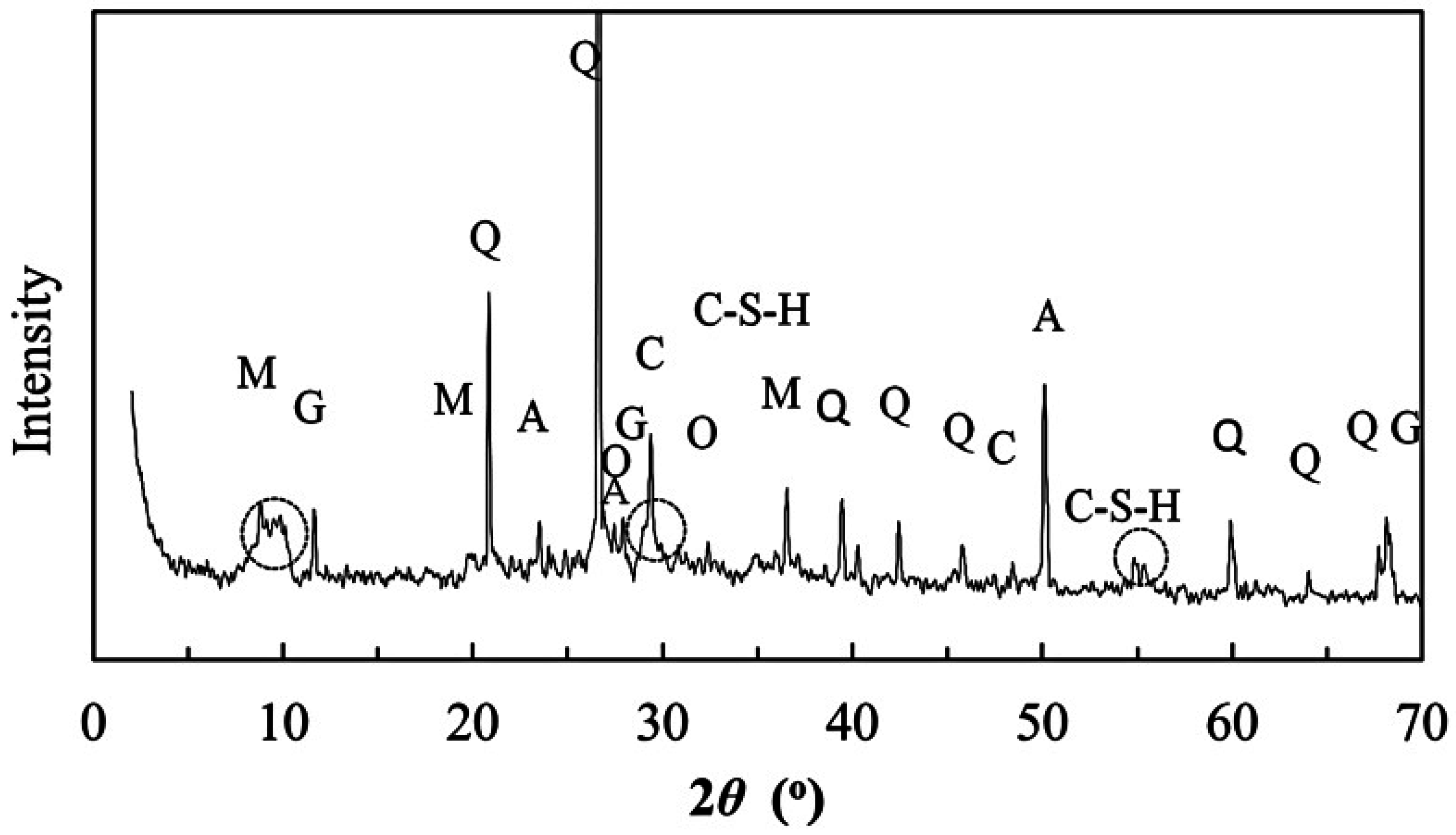
3.1. Mineral Components
3.2 Validation of Indentation Depth
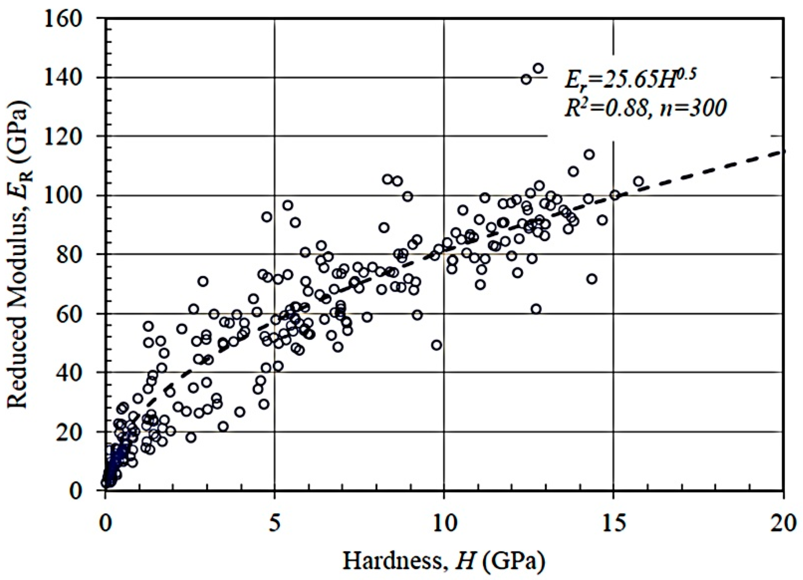
3.3. Statistical Analysis on Indentation Modulus and Hardness
3.4. Comparative Analysis
3.4.1. Quartz
3.4.2. C-S-H
3.4.3. Calcite
3.4.4. Geopolymer
4. Conclusions
Acknowledgments
Author Contributions
Conflicts of Interest
References
- Elsen, J. Microscopy of historic mortars—A review. Cem. Concr. Res. 2006, 36, 1416–1424. [Google Scholar] [CrossRef]
- Moropoulou, A.; Bakolas, A.; Anagnostopoulou, S. Composite materials in ancient structures. Cem. Concr. Compos. 2005, 27, 295–300. [Google Scholar] [CrossRef]
- Sağın, E.U.; Böke, H.; Aras, N.; Yalçın, Ş. Determination of CaCO3 and SiO2 content in the binders of historic lime mortars. Mater. Struct. 2011, 45, 841–849. [Google Scholar] [CrossRef]
- Sandrolini, F.; Franzoni, E. Characterization procedure for ancient mortars’ restoration: The plasters of the Cavallerizza courtyard in the Ducal Palace in Mantua (Italy). Mater. Charact. 2010, 61, 97–104. [Google Scholar] [CrossRef]
- Silva, A.S.; Cruz, T.; Paiva, M.J.; Candeias, A.; Adriano, P.; Schiavon, N.; Mirão, J.A.P. Mineralogical and chemical characterization of historical mortars from military fortifications in Lisbon harbour (Portugal). Environ. Earth Sci. 2011, 63, 1641–1650. [Google Scholar] [CrossRef]
- Yang, F.; Zhang, B.; Ma, Q. Study of Sticky Rice-Lime Mortar Technology for the Restoration of Historical Masonry Construction. Acc. Chem. Res. 2010, 43, 936–944. [Google Scholar] [CrossRef] [PubMed]
- Song, Y. The Exploitation of the Works of Nature; Commercial Press: Shanghai, China, 1933; p. 197. [Google Scholar]
- Fang, S.; Zhang, H.; Zhang, B.; Li, G. A study of Tung-oil-lime putty—A traditional lime based mortar. Int. J. Adhes. Adhes. 2014, 48, 224–230. [Google Scholar] [CrossRef]
- Fang, S.; Zhang, H.; Zhang, B.; Wei, G.; Li, G.; Zhou, Y. A study of the Chinese organic–inorganic hybrid sealing material used in “Huaguang No.1” ancient wooden ship. Thermochim. Acta 2013, 551, 20–26. [Google Scholar] [CrossRef]
- Wei, G.; Zhang, H.; Wang, H.; Fang, S.; Zhang, B.; Yang, F. An experimental study on application of sticky rice–lime mortar in conservation of the stone tower in the Xiangji Temple. Constr. Build. Mater. 2012, 28, 624–632. [Google Scholar] [CrossRef]
- Zeng, Y.; Zhang, B.; Liang, X. A case study and mechanism investigation of typical mortars used on ancient architecture in China. Thermochim. Acta 2008, 473, 1–6. [Google Scholar] [CrossRef]
- Xie, H. Construction Technology of Rammed-Earth Construction of Fujian Earth Building. Hous. Sci. 2004, 39–42. [Google Scholar] [CrossRef]
- Ulm, F.-J.; Vandamme, M.; Bobko, C.; Alberto Ortega, J.; Tai, K.; Ortiz, C. Statistical Indentation Techniques for Hydrated Nanocomposites: Concrete, Bone, and Shale. J. Am. Ceram. Soc. 2007, 90, 2677–2692. [Google Scholar] [CrossRef]
- Sakulich, A.R.; Li, V.C. Nanoscale characterization of engineered cementitious composites (ECC). Cem. Concr. Res. 2011, 41, 169–175. [Google Scholar] [CrossRef]
- Cook, H.E.; Johnson, P.D.; Matti, J.C.; Zemmels, I. Methods of Sample Preparation and X-ray Diffraction Data Analysis, X-ray Mineralogy Laboratory, Deep Sea Drilling Project, University of California, Riverside; Initial Reports of the Deep Sea Drilling Project; Texas A & M University: College Station, TX, USA, 1975; pp. 999–1007. [Google Scholar]
- Oliver, W.C.; Pharr, G.M. An improved technique for determining hardness and elastic-modulus using load and displacement sensing indentation experiments. J. Mater. Res. 1992, 7, 1564–1583. [Google Scholar] [CrossRef]
- Oliver, W.C.; Pharr, G. Measurement of hardness and elastic modulus by instrumented indentation: Advances in understanding and refinements to methodology. J. Mater. Res. 2004, 19, 3–20. [Google Scholar] [CrossRef]
- Sneddon, I.N. The relation between load and penetration in the axisymmetric boussinesq problem for a punch of arbitrary profile. Int. J. Eng. Sci. 1965, 3, 47–57. [Google Scholar] [CrossRef]
- Constantinides, G.; Ulm, F.-J.; van Vliet, K. On the use of nanoindentation for cementitious materials. Mater. Struct. 2003, 36, 191–196. [Google Scholar] [CrossRef]
- Constantinides, G.; Ravi Chandran, K.S.; Ulm, F.J.; van Vliet, K.J. Grid indentation analysis of composite microstructure and mechanics: Principles and validation. Mater. Sci. Eng. A 2006, 430, 189–202. [Google Scholar] [CrossRef]
- Maravelaki-Kalaitzaki, P. Physico-chemical study of Cretan ancient mortars. Cem. Concr. Res. 2003, 33, 651–661. [Google Scholar] [CrossRef]
- Pant, R.R. Nanoindentation Characterization of Clay Minerals and Clay-Based Hybrid Bio-Geomaterials. Ph.D. Thesis, Louisiana State University, Baton Rouge, LA, USA, 23 August 2013. [Google Scholar]
- Joseph, D. Ancient and Modern Concretes: What is the Real Difference? Concr. Int. 1987, 9, 23–28. [Google Scholar]
- Alonso, S.; Palomo, A. Calorimetric study of alkaline activation of calcium hydroxide–metakaolin solid mixtures. Cem. Concr. Res. 2001, 31, 25–30. [Google Scholar] [CrossRef]
- Granizo, M.L.; Alonso, S.; Blanco-Varela, M.T.; Palomo, A. Alkaline Activation of Metakaolin: Effect of Calcium Hydroxide in the Products of Reaction. J. Am. Ceram. Soc. 2004, 85, 225–231. [Google Scholar] [CrossRef]
- Yip, C.K.; Lukey, G.C.; van Deventer, J.S.J. The coexistence of geopolymeric gel and calcium silicate hydrate at the early stage of alkaline activation. Cem. Concr. Res. 2005, 35, 1688–1697. [Google Scholar] [CrossRef]
- Jennings, H.M. A model for the microstructure of calcium silicate hydrate in cement paste. Cem. Concr. Res. 2000, 30, 101–116. [Google Scholar] [CrossRef]
- Jennings, H.M.; Bullard, J.W.; Thomas, J.J.; Andrade, J.E.; Chen, J.J.; Scherer, G.W. Characterization and Modeling of Pores and Surfaces in Cement Paste. J. Adv. Concr. Technol. 2008, 6, 5–29. [Google Scholar] [CrossRef]
- Richardson, I.G. The calcium silicate hydrates. Cem. Concr. Res. 2008, 38, 137–158. [Google Scholar] [CrossRef]
- Richardson, I.G.; Skibsted, J.; Black, L.; Kirkpatrick, R.J. Characterisation of cement hydrate phases by TEM, NMR and Raman spectroscopy. Adv. Cem. Res. 2010, 22, 233–248. [Google Scholar] [CrossRef]
- Donnelly, E.; Baker, S.P.; Boskey, A.L.; van der Meulen, M.C. Effects of surface roughness and maximum load on the mechanical properties of cancellous bone measured by nanoindentation. J. Biomed. Mater. Res. Part A 2006, 77, 426–435. [Google Scholar] [CrossRef] [PubMed]
- Bobko, C.; Ulm, F.-J. The nano-mechanical morphology of shale. Mech. Mater. 2008, 40, 318–337. [Google Scholar] [CrossRef]
- Zhu, W.; Hughes, J.J.; Bicanic, N.; Pearce, C.J. Nanoindentation mapping of mechanical properties of cement paste and natural rocks. Mater. Charact. 2007, 58, 1189–1198. [Google Scholar] [CrossRef]
- Constantinides, G.; Ulm, F.-J. The nanogranular nature of C-S-H. J. Mech. Phys. Solids 2007, 55, 64–90. [Google Scholar] [CrossRef]
- Jennings, H.M.; Thomas, J.J.; Gevrenov, J.S.; Constantinides, G.; Ulm, F.-J. A multi-technique investigation of the nanoporosity of cement paste. Cem. Concr. Res. 2007, 37, 329–336. [Google Scholar] [CrossRef]
- Bao, Y.W.; Wang, W.; Zhou, Y.C. Investigation of the relationship between elastic modulus and hardness based on depth-sensing indentation measurements. Acta Mater. 2004, 52, 5397–5404. [Google Scholar] [CrossRef]
- Constantinides, G.; Ulm, F.-J. The effect of two types of C-S-H on the elasticity of cement-based materials: Results from nanoindentation and micromechanical modeling. Cem. Concr. Res. 2004, 34, 67–80. [Google Scholar] [CrossRef]
- Mondal, P.; Shah, S.P.; Marks, L. A reliable technique to determine the local mechanical properties at the nanoscale for cementitious materials. Cem. Concr. Res. 2007, 37, 1440–1444. [Google Scholar] [CrossRef]
- Vandamme, M.; Ulm, F.-J.; Bažant, Z.P. Nanogranular origin of concrete creep. Proc. Natl. Acad. Sci. USA 2009, 106, 10552–10557. [Google Scholar] [CrossRef] [PubMed]
- Vandamme, M.; Ulm, F.-J.; Fonollosa, P. Nanogranular packing of C-S-H at substochiometric conditions. Cem. Concr. Res. 2010, 40, 14–26. [Google Scholar] [CrossRef]
- Ma, Y.; Cohen, S.R.; Addadi, L.; Weiner, S. Sea Urchin Tooth Design: An “All-Calcite” Polycrystalline Reinforced Fiber Composite for Grinding Rocks. Adv. Mater. 2008, 20, 1555–1559. [Google Scholar] [CrossRef]
- Broz, M.E.; Cook, R.F.; Whitney, D.L. Microhardness, toughness, and modulus of Mohs scale minerals. Am. Mineral. 2006, 91, 135–142. [Google Scholar] [CrossRef]
- Presser, V.; Gerlach, K.; Vohrer, A.; Nickel, K.G.; Dreher, W.F. Determination of the elastic modulus of highly porous samples by nanoindentation: A case study on sea urchin spines. J. Mater. Sci. 2010, 45, 2408–2418. [Google Scholar] [CrossRef]
- Beleña, I.; Zhu, W. Nanoindentation Study of Na-Geopolymers Exposed to High Temperatures. In Nanotechnology in Construction 3: Proceedings of the NICOM3; Bittnar, Z., Bartos, P.J.M., Němeček, J., Šmilauer, V., Zeman, J., Eds.; Springer: Berlin/Heidelberg, Germany, 2009; pp. 169–174. [Google Scholar]
- Lee, H.; Vimonsatit, V.; Chindaprasirt, P. Mechanical and micromechanical properties of alkali activated fly-ash cement based on nano-indentation. Constr. Build. Mater. 2016, 107, 95–102. [Google Scholar] [CrossRef]


| Mineral | Concentration (%) |
|---|---|
| Quartz | 43.0 |
| Feldspar | 9.0 |
| Gypsum/Anhydrite | 2.0 |
| Calcite | 9.0 |
| Amorphous Phase | 37.0 |
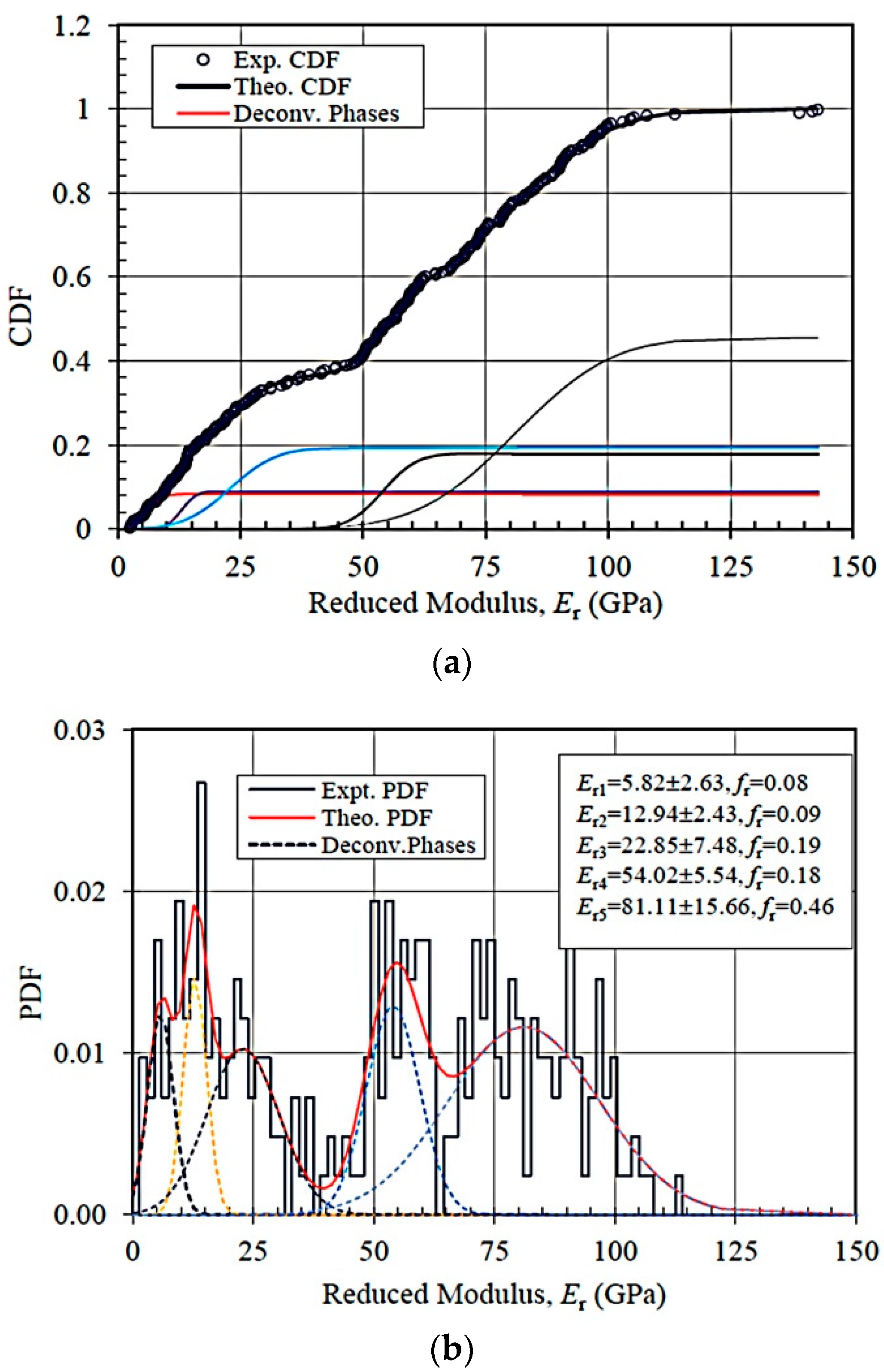
| Trials | Reduced Modulus | Amount of Data | Constituent Phase i | ||||
|---|---|---|---|---|---|---|---|
| MP | MGC | C-S-H | NC | INC | |||
| ANC-1 | μi, GPa | 300 | 5.82 | 12.94 | 22.85 | 54.02 | 81.11 |
| σi, GPa | 2.63 | 2.43 | 7.48 | 5.54 | 15.66 | ||
| fri | 0.08 | 0.09 | 0.19 | 0.18 | 0.46 | ||
| ANC-2 | μi, GPa | 100 | 8.18 | 17.30 | 26.10 | 52.46 | 79.40 |
| σi, GPa | 3.62 | 2.58 | 6.20 | 10.69 | 9.88 | ||
| fri | 0.31 | 0.26 | 0.19 | 0.21 | 0.06 | ||
| ANC-3 | μi, GPa | 100 | 4.80 | 11.60 | 24.30 | 53.40 | 84.00 |
| σi, GPa | 1.50 | 5.4 | 3.5 | 8.9 | 8.7 | ||
| fri | 0.19 | 0.43 | 0.17 | 0.19 | 0.02 | ||
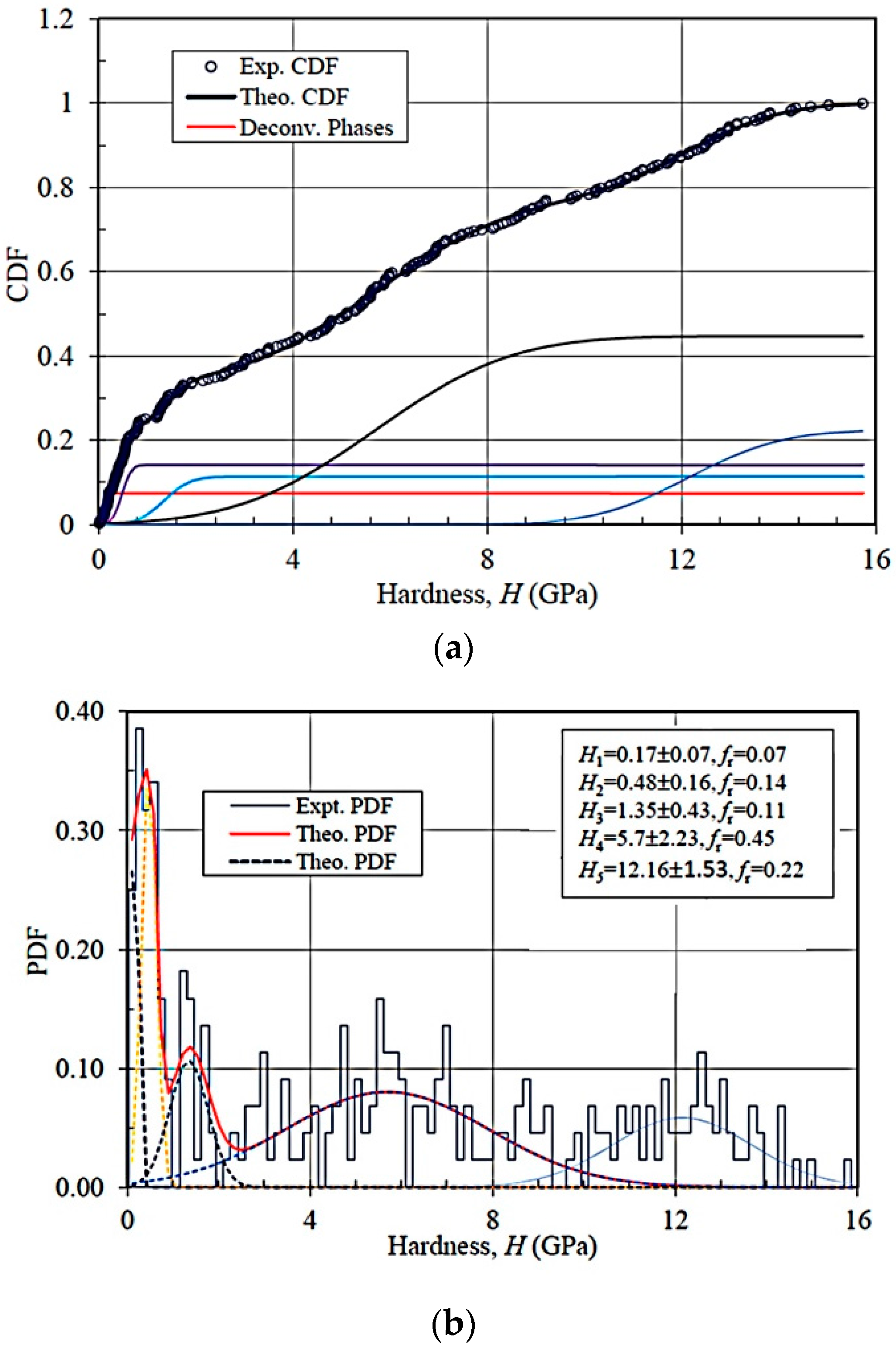
| Trials | Hardness | Amount of Data | Constituent Phase i | ||||
|---|---|---|---|---|---|---|---|
| MP | MGC | C-S-H | NC | INC | |||
| ANC-1 | μi, GPa | 300 | 0.16 | 0.48 | 1.35 | 5.70 | 12.16 |
| σi, GPa | 0.07 | 0.16 | 0.43 | 2.23 | 1.53 | ||
| fri | 0.07 | 0.14 | 0.11 | 0.45 | 0.22 | ||
| ANC-2 | μi, GPa | 100 | 0.28 | 0.62 | 1.21 | 3.27 | 8.41 |
| σi, GPa | 0.10 | 0.25 | 0.11 | 1.94 | 0.45 | ||
| fri | 0.24 | 0.27 | 0.13 | 0.29 | 0.06 | ||
| ANC-3 | μi, GPa | 100 | 0.23 | 0.57 | 1.39 | 5.57 | 12.16 |
| σi, GPa | 0.15 | 0.19 | 0.55 | 2.20 | 1.53 | ||
| fri | 0.41 | 0.18 | 0.17 | 0.22 | 0.02 | ||
| Sample Info. | C-S-H | Er (GPa) | H (GPa) | Method | Reference |
|---|---|---|---|---|---|
| w/c = 0.4 | LD | 21.7 ± 2.2 | — | SNT | [37] |
| HD | 29.4 ± 2.4 | — | |||
| w/c = 0.35, | LD | 23.4 ± 3.4 | 0.73 ± 0.15 | SNT | [33] |
| HD | 31.4 ± 2.1 | 1.27 ± 0.18 | |||
| w/c = 0.5 | LD | 18.1 ± 4.0 | — | SNT | [35] |
| HD | 31.0 ± 4.0 | — | |||
| w/c = 0.5, 5 months | LD | 18.2 ± 4.2 | 0.45 ± 0.14 | SNT | [34] |
| HD | 29.1 ± 4.0 | 0.83 ± 0.18 | |||
| w/c = 0.45 | LS | 22.89 ± 0.76 | 0.93 ± 0.11 | SNT | [38] |
| MS | 31.16 ± 2.51 | 1.22 ± 0.07 | |||
| HS | 41.45 ± 1.75 | 1.43 ± 0.29 | |||
| w/c = 0.3 | LD | 23.7 ± 5.9 | 0.68 ± 0.18 | SNT | [39] |
| HD | 36.1 ± 3.4 | 1.01 ± 0.16 | |||
| w/c = 0.2 | LD | 19.4 ± 4.8 | 0.44 ± 0.23 | SNT | [40] |
| HD | 31.8 ± 6.1 | 0.88 ± 0.21 | |||
| w/c = 0.3 | LD | 21.9 ± 4.9 | 0.58 ± 0.12 | ||
| HD | 31.3 ± 4.5 | 0.87 ± 0.17 | |||
| w/c = 0.35 | LD | 25.6 ± 3.5 | 0.60 ± 0.10 | ||
| HD | 32.0 ± 2.9 | 0.87 ± 0.17 | |||
| w/c = 0.4 | LD | 22.5 ± 5.0 | 0.61 ± 0.17 | ||
| HD | 30.4 ± 2.9 | 0.92 ± 0.10 |
© 2016 by the authors; licensee MDPI, Basel, Switzerland. This article is an open access article distributed under the terms and conditions of the Creative Commons Attribution (CC-BY) license (http://creativecommons.org/licenses/by/4.0/).
Share and Cite
Hou, D.; Zhang, G.; Pant, R.R.; Shen, J.S.; Liu, M.; Luo, H. Nanoindentation Characterization of a Ternary Clay-Based Composite Used in Ancient Chinese Construction. Materials 2016, 9, 866. https://doi.org/10.3390/ma9110866
Hou D, Zhang G, Pant RR, Shen JS, Liu M, Luo H. Nanoindentation Characterization of a Ternary Clay-Based Composite Used in Ancient Chinese Construction. Materials. 2016; 9(11):866. https://doi.org/10.3390/ma9110866
Chicago/Turabian StyleHou, Dongwei, Guoping Zhang, Rohit Raj Pant, Jack S. Shen, Mingming Liu, and Hao Luo. 2016. "Nanoindentation Characterization of a Ternary Clay-Based Composite Used in Ancient Chinese Construction" Materials 9, no. 11: 866. https://doi.org/10.3390/ma9110866
APA StyleHou, D., Zhang, G., Pant, R. R., Shen, J. S., Liu, M., & Luo, H. (2016). Nanoindentation Characterization of a Ternary Clay-Based Composite Used in Ancient Chinese Construction. Materials, 9(11), 866. https://doi.org/10.3390/ma9110866