2.1. Thermal Barrier Performance of Coatings
As mentioned above, the thermal barrier efficiency of intumescent coatings on steel structures is usually evaluated from temperature-time curves obtained from thermocouples embedded on the unexposed surface of steel plate in fire tests and determination of the “time to failure” in terms of time to reach a given temperature, defined by a specific test [
7,
8]. In UL 1709 test, for example the coated surface is exposed to 147 kW propane jet burner that produces 180 kW/m
2 heat flux at the exposed surface and the coating is expected to hold the back surface temperature of the substrate to a maximum of 180 °C for 30 min. This criterion in the test is used because the structural steel loses its load bearing capacity when the temperature exceeds 500 °C. However, in case of composites when the temperature reaches the softening or the glass transition temperature (
Tg) of the resin, ~50% of mechanical properties of the laminate are lost [
15], increasing progressively with rise in temperature leading to 100% loss by decomposition/burning of resin. As an effective thermal barrier protection, the coating should stop or retard the temperature rise at the surface to reach
Tg or the pyrolysis temperature (the temperature at which decomposition of the resin starts) of the epoxy resin. The
Tg of epoxy resin is 150–220 °C, for the resin used in this work is 180 °C, while the onset of decomposition temperature is 250 °C. In this work we have used a cone calorimeter to determine thermal barrier efficiency of these coatings, keeping external heat flux 50 kW/m
2 (commonly used heat flux to test reaction-to-fire properties of composites in developing fires) and measuring the temperature profiles by inserting thermocouples under the coatings and on the back surfaces of the laminates. In cone calorimetric testing of intumescent coatings, usually the distance between the cone heater and the sample is increased from standard 25 to 50 mm [
13] or other suitable distance to compensate for the expansion of the coating [
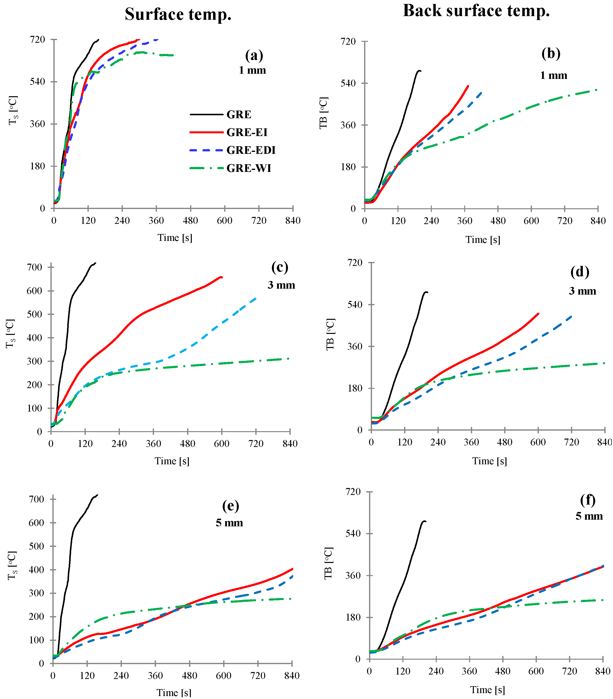
14]. The distance was kept to standard 25 mm in this case as our primary interest was to keep the heat flux constant and study the rate of temperature rise of composite surface during early stages of the char expansion and also to measure the time taken for top and back surfaces of the laminate to reach 180 or 250 °C. The temperatures profiles for 1, 3 and 5 mm thick coatings were noted and are shown in
Figure 1. The thermocouple was placed on the surface, hence is an estimated surface temperature, whereas, for coated laminates, the temperature measured was underneath the coating and represents the temperature at the interface of the laminate and the coating. Times to reach each surface 180 or 250 °C are reported in
Table 1.
Figure 1.
The surface (a,c,e) and back surface temperatures (b,d,f) vs. time for control and GRE-EI, GRE-EDI and GRE-WI coated samples at 50 kW/m2. Coating thickness = 1 mm (a,b), 3 mm (c,d) and 5 mm (e,f). GRE: glass fibre-reinforced epoxy; EI: epoxy based intumescent coating; EDI: flame retarded epoxy based intumescent coating; WI: water based intumescent coating.
As can be seen from
Figure 1a that the surface temperature of the control GRE composite rises sharply reaching softening temperature within 28 s (
Table 1) and the highest value of 720 °C only after 156 s, which indicates very high rate of temperature rise at the surface of uncoated GRE composite. The back surface temperature rise is slower than the surface temperature as can be seen from the slope of the curve, reaching softening temperature within 76 s and maximum 590 °C after 191 s. With 1 mm thick coating the temperature rise on the surface (
Figure 1a) is similar to the control for ~30 s, and once the coating is expanded some difference in the temperature can be seen. The temperature rise of the back surface is much slower. All three coatings behave similarly for first 156 s (
Figure 1b), then the thermal barrier efficiency depends upon the expanded char. The effect is more pronounced as the coating thickness and the char thickness increases. The efficiency of coatings in terms to time to reach 180 or 250 °C is as: WI > EDI > EI.
This effect is directly proportional to the thickness of the char as seen in
Table 1. As the thickness gets to 5 mm, all charred structures are thick enough to act as efficient thermal barriers as can be seen from
Figure 1e,f.
Table 1.
Thermal barrier properties of different intumescent coatings of varying thicknesses on glass fibre-reinforced epoxy (GRE) composite samples, exposed to 50 kW/m2 heat flux.
Table 1.
Thermal barrier properties of different intumescent coatings of varying thicknesses on glass fibre-reinforced epoxy (GRE) composite samples, exposed to 50 kW/m2 heat flux.
| Sample | Coating Thickness (mm) | Char Thickness | Time to Reach 180 °C (s) | Time to Reach 250 °C (s) |
|---|
| Exposure time (s) | Char thickness (mm) |
|---|
| Surface | Back | Surface | Back |
|---|
| Control | - | 200 | - | 28 | 76 | 37 | 95 |
| GRE-EI | 1.27 ± 0.01 | 500 | 6.8 ± 2.2 | 33 | 114 | 43 | 164 |
| 2.96 ± 0.16 | 900 | 10.0 ± 2.0 | 65 | 176 | 98 | 258 |
| 5.28 ± 0.22 | 1400 | 15.8 ± 0.9 | 338 | 472 | 471 | 495 |
| GRE-EDI | 1.35 ± 0.02 | 500 | 9.8 ± 2.8 | 38 | 107 | 56 | 152 |
| 2.95 ± 0.09 | 900 | 20.7 ± 1.3 | 107 | 222 | 208 | 339 |
| 5.72 ± 0.09 | 1600 | 27.2 ± 2.7 | 337 | 507 | 507 | 537 |
| GRE-WI | 0.94 ± 0.03 | 800 | 24.1 ± 2.6 | 32 | 109 | 48 | 193 |
| 2.91 ± 0.09 | 800 | 41.7 ± 2.4 | 110 | 166 | 236 | 438 |
| 5.25 ± 0.82 | 1200 | 36.3 ± 4.5 | 153 | 494 | 494 | 759 |
As seen from
Table 1 when the samples is protected by 1 mm thick coating, there is no significant delay in time (~5–10 s on surface and 31–38 s back surface) to reach 180 °C, however, a 3 mm thick coating significantly delayed the time to reach 180, with further delay in 5 mm coatings. A similar effect is seen for the time required to reach the pyrolysis temperature of the resin (250 °C) on the surface and back surface for all coated samples. That means with the 1 mm coatings of GRE-EI, GRE-EDI and GRE-WI, the GRE composite will start losing its mechanical properties in a short period of time after exposure to a high heat source. Coatings of ≥3 mm thickness could provide longer time to retain the mechanical properties. However, on a 3 mm thick laminate it is impractical to have a coating of >1mm thickness, hence the rest of the work was done on 1 mm thick coatings.
2.2. Thermo-Physical Properties of Intumescent Char
The basic principle of an intumescent coating is that on exposure to heat it expands and the low thermal conductivity of the expanded char provides a thermal barrier effect. Hence, quantitative information about both of these parameters can help in designing and developing new coatings.
Due to commercial sensitivity of the coatings used here, their exact compositions are not provided. Hence, results cannot be analyzed in terms of their compositions and mechanism of intumescence. In general the expansion of an intumescent coating after activation by fire or heat occurs as a sequential chemical reaction between the three active components (acid source, carbonific, and blowing agent), which generally involves the decomposition of the acid source to generate a mineral acid, and then the acid reacts with the carbonization agent to form the carbonaceous char, while the blowing agent generates the gases. The formed gases expand the char. The swelling occurs due to the gases released following heating becoming trapped in the viscous fluid char layer and increasing the volume of the coating, and then a multi-cellular char structure of low thermal conductivity containing voids (bubbles) is formed. The expansion continues until the blowing agent is exhausted, or the solid matrix is insufficiently elastic. The polymer binder used in a coating on heating promotes crosslinking reactions, and hardens the structure. Type of polymer binder used also affects the char expansion, its porosity and hence, thermal conductivity as is the case in EI and EDI coatings, which are similar in composition and the binder (epoxy resin) type except that in EDI epoxy resin is reacted with DOPO.
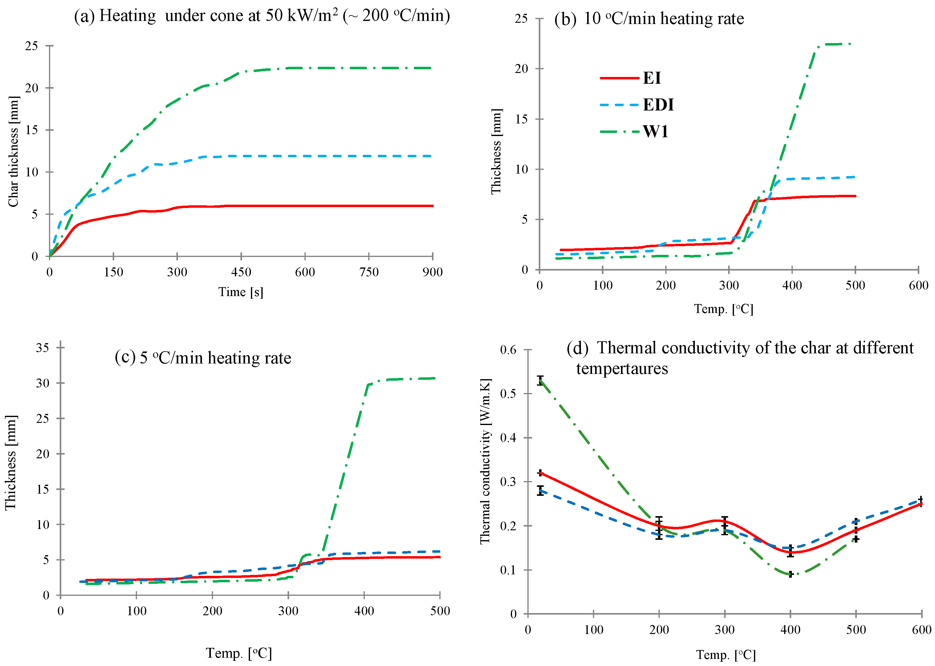
The char expansion of these intumescent coatings under different conditions was measured. The results for expansion as a function of time measured during mass loss calorimeter experiments at 50 kW/m
2 using an infrared camera (discussed in details elsewhere [
2]) are shown in
Figure 2a. In this experiment, a constant heat flux is applied to the surface of the sample and with ~200 °C/min heating rate (estimated from the slopes of temperature profiles in
Figure 1) the char expands very quickly and once the surface temperature stabilizes, the char expansion/oxidation behavior becomes time dependent. As can be seen from
Figure 2a, in this experiment both EI and EDI coatings started expanding immediately and rate of expansion was very high until 80 s, after which expansion was slower and became constant after 300 s. For WI coating, the char kept expanding until 450 s and then stopped.
However, when these coatings (without a substrate) are heated in a rheometer, where the heating is uniform on all sides and the heating rate is very low (5 and 10 °C/min), the expansion behaviors of three coatings are very different. All three intumescent coatings expand in two distinct stages; in the first stage char expansion is slow, whereas in the second stage expansion rate is much higher (
Figure 2b,c). In epoxy based EI and EDI coatings, the first significant expansion started at ~180 °C and then the second expansion occurred at ~300 °C. On the other hand, water based WI water coating started expanding at ~300 °C, followed by the second major expansion occurring after 350 °C. The effect of heating rate on char expansion of these intumescent coatings can also be observed from
Figure 2b,c. At 10 °C/min heating rate the expansion for all three coatings follows a similar pattern as seen from cone calorimetric results, although the actual values and rate of expansion are different due to different heating regimes. However, on reducing heating rate to 5 °C/min, the trend is very different,
i.e., while the expansion of EI and EDI slightly decreased from those at 10 °C/min, it increased in WI coating. This is clearer from
Table 2, where the char expansion ratios (char thickness/coating thickness) are presented. This different trend is probably due to the EI and EDI being epoxy based intumescent coating systems, require a higher heat treatment to build up the char, whereas the water based intumescent coating (WI) could char better at the lower heating condition.
As seen from
Table 2, while the expansion ratios are different depending on the heating conditions, the trend for expansion is similar in all cases as: WI > EDI > EI, which indicates that WI coating can provide higher expanded char compared to EI and EDI coatings under all conditions. The thermal barrier efficiencies of these three coatings however, are very similar for first ~150 s as seen from
Figure 1b, also indicated by the time taken to reach surface temperature of the laminate 180 (glass transition temp of resin) or 250 °C (decomposition temperature of the resin) from
Table 2, which is due to the fact that it is not just the thickness but also the thermal conductivity, which affects the heat transfer through the coating.
Figure 2.
(a–c) The intumescent coatings’ expansion: (a) On the substrate as a function of time when exposed to a radiant heat of 50 kW/m2 in a mass loss calorimeter. (b,c) As a function of temperature at 10 and 5 °C/min respectively in a rheometer and (d) thermal conductivities as a function of temperature obtained by hot disk method.
Table 2.
The char expansion ratios from different experiments using different heating conditions.
Table 2.
The char expansion ratios from different experiments using different heating conditions.
| Testing | Char Expansion Ratio * |
|---|
| EI | EDI | WI |
|---|
| Cone calorimetry | 5.3 | 7.2 | 25.6 |
| Mass calorimeter | 5.8 | 7.2 | 35.2 |
| Rheometer: 10 °C/min | 4.0 | 5.1 | 20.7 |
| Rheometer: 5 °C/min | 2.6 | 3.1 | 22.1 |
The thermal conductivity values of the three coatings at different temperatures varying from room temperature to 700 °C by using hot disk method (measured at 100 °C intervals) are plotted in
Figure 2d. The thermal conductivity values for all intumescent chars vary from 0.1 to 0.4 W/mK, which is similar to that as reported in literature [
16,
17]. While at room temperature, WI coating has the highest thermal conductivity value of 0.53 W/mK than EDI (0.32 W/mK) and EI (0.27 W/mK), the values at higher temperatures differ less from each other. The thermal conductivities of these three coatings first decreased and then increased with increasing temperature (
Figure 2d). The first significant drop was observed at 200 °C, which remained constant until 300 °C and then decreased again, the minimum being at 400 °C, after which the values increased and kept increasing until 700 °C. This behavior is characteristic of an intumescent material, when exposed to high temperature the material expands and forms a porous char structure of low heat conductivity. Hence, as the char expands due to increase in porosity the thermal conductivity decreases. Above 400 °C, the char structure does not change significantly and hence thermal conductivity increases as a function of temperature [
16]. This behavior corroborates very well with the char expansion study shown in
Figure 2b. However, despite different char thicknesses, their thermal conductivities are very similar, which is due to the fact that while thermal conductivity is the material’s intrinsic property, it also depends upon the char structure and its porosity. These parameters are useful in designing surface coatings that can protect a particular substrate from a defined thermal threat for a specified period of time. For example, in case of composites used in this work, since glass transition temperature and decomposition temperature of the epoxy resin are ~180 and 250 °C, a temperature point at 200 °C was selected to evaluate the minimum requirement for both of thermal conductivity and coating thickness in order to protect the underlying composite structure. The results from
Figure 2 and
Table 3 indicate that ~0.2 W/mK is the minimum thermal conductivity value of the char that should be able to protect a composite structure from heat to maintain structural integrity for a period of time.
Table 3.
The thermal conductivity and char thickness requirements of intumescent coatings to protect the composite surface temperature to reach 200 °C.
Table 3.
The thermal conductivity and char thickness requirements of intumescent coatings to protect the composite surface temperature to reach 200 °C.
| Coating | Surface Temperature of the Laminate, underneath the Coating (°C) | Char Thickness (mm) | Thermal Conductivity (W/mK) |
|---|
| EI | 200 | 3.2 | 0.20 |
| EDI | 200 | 5.1 | 0.18 |
| WI | 200 | 6.5 | 0.20 |


