1. Introduction
Thaumasite sulfate attack (TSA) is a severe form of sulfate-induced deterioration in cement-based materials, characterized by the transformation of cementitious phases into non-cementitious products, resulting in significant strength degradation and structural instability. Since its first identification in 1965 [
1], TSA has been widely reported in hydraulic structures and underground engineering, posing a serious threat to the durability and serviceability of concrete infrastructures. Recent reviews have further summarized the formation pathways, influencing factors, and mitigation strategies of TSA in cement-based materials, emphasizing that thaumasite formation is closely related to the simultaneous availability of sulfate, carbonate, calcium, and silicate sources, as well as environmental conditions such as temperature and moisture supply [
2,
3]. In addition, recent studies on sulfate attack have highlighted that the deterioration of cement-based materials should be understood as a coupled process involving ion transport, chemical reactions, crystallization or precipitation of corrosion products, and the subsequent degradation of mechanical properties [
4,
5].
With the increasing demand for deep underground resource exploitation, the depth of mine shafts has continuously increased, leading to more severe service conditions for concrete structures [
6,
7,
8,
9]. In deep underground environments, concrete shaft linings are subjected to the combined effects of high ground stress, sulfate-rich groundwater, and elevated water pressure, which significantly accelerate deterioration processes [
10,
11,
12,
13,
14]. Field investigations have reported severe damage in shaft structures exposed to such environments. For example, in Laiwu Mine (Shandong, China), serious corrosion of the shaft lining occurred within less than 5 years of service, with material degradation reaching depths of 5–10 cm, allowing manual disintegration of the concrete [
15]. Similarly, in the Mataihao Coal Mine (Inner Mongolia, China), rapid deterioration, including peeling, pulverization, and shedding, was observed, with corrosion depths of 8–15 cm under groundwater sulfate concentrations exceeding 1500 mg/L [
16]. Similar TSA-related damage has also been reported in buried concrete structures, such as highway bridges and tunnels [
17,
18,
19,
20,
21]. These observations indicate that TSA under high water pressure is a critical durability issue in deep underground engineering. Under such conditions, sulfate ingress driven by water pressure may become an important factor governing deterioration. The penetration of sulfate ions into the concrete matrix, coupled with sustained water pressure, promotes ion transport, accelerates internal reactions, and leads to progressive damage from the surface to the interior. Despite the severe engineering implications, the mechanisms of TSA under elevated water pressure remain insufficiently understood.
Extensive studies have been conducted to investigate the mechanisms and influencing factors of TSA in cement-based materials. Recent reviews have indicated that TSA development is affected by multiple factors, including temperature, sulfate concentration, and the availability of carbonate ions [
2,
22,
23,
24]. Among these factors, carbonate availability is particularly important because thaumasite formation requires the participation of carbonate together with sulfate, calcium, and silicate species. Therefore, limestone powder, which is increasingly used as a partial cement replacement or filler, may increase the risk of TSA by providing an additional carbonate source under suitable exposure conditions [
25,
26,
27,
28]. Recent experimental studies on limestone powder-containing cementitious systems have also shown that sulfate attack behavior is strongly dependent on temperature and exposure conditions, and thaumasite-related deterioration is more likely to occur under low-temperature sulfate environments [
26]. However, most existing studies have been performed under normal or low water pressure conditions (typically below 3 MPa), where ion transport is primarily governed by diffusion. Recent experimental evidence on TSA and sulfate-exposed mortars still mainly concerns conventional exposure conditions, while systematic studies under elevated water pressure remain scarce [
29,
30]. Under such conditions, gypsum and ettringite are generally considered the main corrosion products, and the formation of thaumasite is relatively limited.
Although recent studies have improved the understanding of TSA mechanisms, sulfate attack testing methods, transport–reaction–damage coupling, and the influence of water pressure or water penetration on concrete damage and transport behavior, the role of elevated water pressure in TSA remains insufficiently clarified [
4,
12,
13,
25,
26]. In deep underground environments, water pressure can reach several megapascals, which may promote the ingress of sulfate solution and influence transport and reaction processes within the cement matrix. However, the coupling between water pressure-assisted sulfate supply and limestone powder-derived carbonate availability has rarely been systematically investigated. Moreover, the influence of elevated water pressure on corrosion product evolution, spatial distribution, and the associated deterioration mechanism remains unclear.
Therefore, this study aims to investigate the degradation behavior of cement mortar subjected to TSA under the combined effects of elevated water pressure and limestone powder, with particular attention to their coupling in sulfate transport, corrosion product formation, and macroscopic performance degradation. Specifically, this study attempts to answer the following questions: whether elevated water pressure promotes the migration of sulfate solution into mortar; whether the carbonate source provided by limestone powder changes the formation characteristics of TSA-related corrosion products; and whether the simultaneous presence of water pressure-driven sulfate supply and limestone powder-derived carbonate supply jointly affects corrosion product evolution, spatial distribution, and strength degradation of mortar. To this end, accelerated sulfate exposure tests were conducted on mortar specimens with different limestone powder contents under controlled water pressure environments. Compressive strength testing, depth-dependent soluble SO42− content measurements, and microstructural characterization using XRD, FT-IR, and SEM/EDS were combined to analyze the coupled effects of elevated water pressure and limestone powder on TSA deterioration.
2. Experimental Procedure
To investigate the coupled effects of elevated water pressure and limestone powder on TSA in cement mortar, a two-factor accelerated corrosion test was designed with different limestone powder contents and water pressure levels. This design was used not only to evaluate the individual effects of water pressure and limestone powder content on mortar deterioration, but also to analyze their interaction in sulfate transport, corrosion product formation, and macroscopic performance degradation. By characterizing compressive strength, macroscopic deterioration morphology, corrosion products, and microstructural features during exposure, the deterioration evolution of cement mortar under elevated water pressure was analyzed. For this purpose, X-ray diffraction (XRD), Fourier-transform infrared spectroscopy (FT-IR), and scanning electron microscopy with energy-dispersive spectroscopy (SEM/EDS) were used to analyze the corrosion products, while supplementary soluble SO42− content measurements were used to support the interpretation of sulfate ingress characteristics. This section sequentially describes the raw materials and mixture proportions, specimen preparation and curing, elevated-water-pressure exposure system and test design, sample collection and preparation, testing methods and data processing.
2.1. Materials and Mixture Proportions
To simulate the deterioration process of cement-based materials under the combined action of sulfate ions and carbonate ions in underground environments, mortar specimens incorporating different proportions of limestone powder were prepared. The introduction of limestone powder provided an internal carbonate source for thaumasite formation and was also used to examine the influence of carbonate availability on TSA development [
26,
28].
P·O 42.5 Portland cement supplied by Xuzhou-Zhonglian Cement Co., Ltd. (Xuzhou, China), quartz sand (particle size 0.2–2 mm) supplied by Lianyungang-Dingmai Quartz Products Co., Ltd. (Lianyungang, China), limestone powder (200 mesh, purity > 98%, whiteness > 95%) produced by Baoxing-Zhangzheng Powder Co., Ltd. (Ya’an, China), and tap water were used to prepare the mortar specimens. The chemical composition of the cement is presented in
Table 1. The sulfate corrosion solution was prepared using analytical-grade anhydrous sodium sulfate with a purity greater than 99%. According to the limestone powder content, the specimens were divided into three groups: 0%, 15%, and 30%, corresponding to groups B1, B2, and B3, respectively. The mortar mixture proportions are shown in
Table 2.
2.2. Specimen Preparation and Curing
Mortar specimens were prepared according to the mixture proportions shown in
Table 2. Mortar specimens with dimensions of 70.7 mm × 70.7 mm × 70.7 mm were cast in steel molds. After casting, the specimens were stored in a laboratory environment at (20 ± 5) °C for 72 h before demolding. Subsequently, all specimens were cured under standard conditions at (20 ± 2) °C and a relative humidity of 95% for 28 days. After curing, the specimens were grouped according to the subsequent test scheme and used for elevated water pressure sulfate exposure tests.
2.3. Test Procedure
2.3.1. Elevated Water Pressure Corrosion Test System
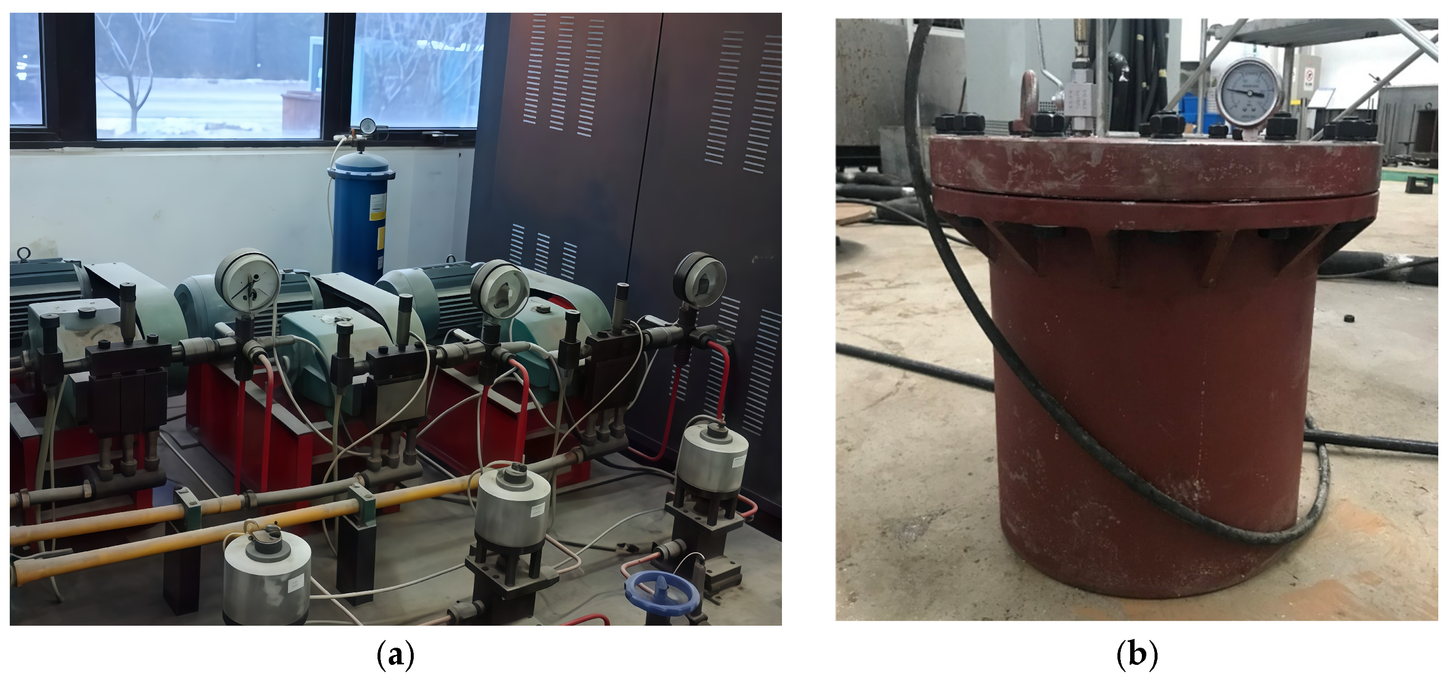
To simulate the service conditions of cement mortar under the combined action of sulfate solution and elevated water pressure in deep underground environments, a servo-controlled pressure stabilization system was used for the test, as shown in
Figure 1a. The system consists of independent high-pressure oil and water circuits and can realize stable loading and continuous control of water pressure. The maximum loading pressure of the system is 80 MPa, with an accuracy of 0.1 MPa, which satisfies the requirements of the exposure tests at different water pressure levels in this study.
To provide a pressurized corrosion environment, a cylindrical pressure vessel made of 45 steel (code name U20452, yield strength 355 MPa) was used, as shown in
Figure 1b. The vessel has an inner radius of 0.2 m and a height of 0.4 m. The wall thickness was set to 10 mm, corresponding to approximately 3.57 times the theoretical value, to ensure adequate safety under high-pressure conditions.
2.3.2. Description of the Water Pressure Action Mode
In this study, the mortar specimens were directly immersed in sodium sulfate solution and subjected to a constant external water pressure to simulate the long-term corrosion of cement-based materials by sulfate-rich groundwater under elevated water pressure in deep underground environments. Compared with atmospheric immersion, the external solution under elevated water pressure is more likely to migrate into the specimen along surface pores and pre-existing defects, thereby increasing the contact opportunities between the aggressive medium and internal hydration products and accelerating the development of corrosion reactions.
Therefore, the pressurized exposure conditions in this study are mainly used to characterize the promoting effect of water pressure on sulfate ingress and damage evolution, rather than simply representing hydrostatic saturation of the material. In combination with mortar specimens containing different limestone powder contents, this design further enables analysis of the combined action of water pressure-driven transport and carbonate availability during TSA deterioration.
2.3.3. Test Design and Grouping
A two-factor experimental design was adopted in this study, with limestone powder content and water pressure level serving as the main variables. The limestone powder contents were set at 0%, 15% and 30%, corresponding to groups B1, B2 and B3, respectively. The water pressure levels were set at 0 MPa, 2.5 MPa, and 5.0 MPa, where 0 MPa represents atmospheric immersion and 2.5 MPa and 5.0 MPa represent elevated water pressure exposure. All specimens were immersed in a 10 wt% Na2SO4 solution to simulate a sulfate-rich groundwater environment. The purpose of this two-factor design was not only to compare the effects of a single water pressure level or a single limestone powder content on deterioration, but more importantly to evaluate their coupling in sulfate transport, corrosion product formation, and strength degradation.
According to the above variable combinations, a total of nine test conditions were established. The specimen group IDs and corresponding test conditions are listed in
Table 3. For each group ID, the first part indicates the limestone powder content group, while the second part indicates the water pressure level. For example, B2-3 denotes specimens with 15% limestone powder content exposed to a water pressure of 5.0 MPa. The exposure ages for all groups were set as 30 d, 60 d, 90 d, and 120 d.
2.3.4. Exposure Conditions and Test Procedure
After 28 d of standard curing, the mortar specimens in each group were placed in a 10 wt% Na2SO4 solution for corrosion exposure. The test temperature was the natural room temperature in autumn and winter, approximately (12 ± 5) °C, and the volume ratio of solution to specimens was approximately 3:1. To maintain the stability of the corrosion environment, the sulfate solution was renewed every 15 d during the test.
The specimens in the atmospheric immersion group were placed in sealed plastic containers. Their exposure temperature, solution-to-specimen volume ratio, solution renewal interval, and sampling ages were kept consistent with those of the elevated water pressure groups. For the high-pressure immersion groups, the specimens were placed in the high-pressure reactor and continuously exposed to sodium sulfate solution under the corresponding applied water pressure. During the test, the pressure state was monitored and adjusted in real time using the servo-controlled pressure stabilization system to ensure that each group of specimens remained under the preset pressure condition.
At the specified exposure ages, the corresponding specimens were removed for subsequent testing and analysis. After sampling, the specimen surfaces were first cleaned and labeled, and their apparent deterioration morphology was recorded. The specimens were then used for compressive strength testing, microstructural characterization, or soluble SO42− content testing according to the testing purpose. Throughout the test, all exposure conditions except for the preset water pressure were kept as consistent as possible among the different groups to ensure comparability of the results.
In particular, to support the analysis of sulfate ingress characteristics under different water pressure conditions, additional one-dimensional corrosion specimens were prepared for soluble SO
42− content measurements. Their sampling and sample preparation methods are described in
Section 2.4.2.
2.4. Sampling and Sample Preparation
2.4.1. Sampling and Preparation of Samples for Microstructural Analysis
After reaching the specified exposure age, one representative sample was selected from the corresponding test group for XRD, FT-IR, or SEM/EDS microstructural analysis. To compare differences in the composition and morphology of corrosion products in different regions, surface and internal samples were collected separately. Surface samples were mainly taken from gray–white loose corrosion products near the exposed surface. Internal samples were collected from dense regions away from the outer surface after splitting the specimen, so as to minimize the influence of surface corrosion products on the internal analysis results. For specimens used to compare surface and internal corrosion products, the surface and internal samples were taken from different regions of the same specimen to improve the correspondence and comparability among the different test results. It should be noted that, except for compressive strength tests, the XRD, FT-IR, and SEM/EDS tests in this study were conducted on representative samples and were mainly used for qualitative or semi-quantitative analysis rather than statistical replicate testing.
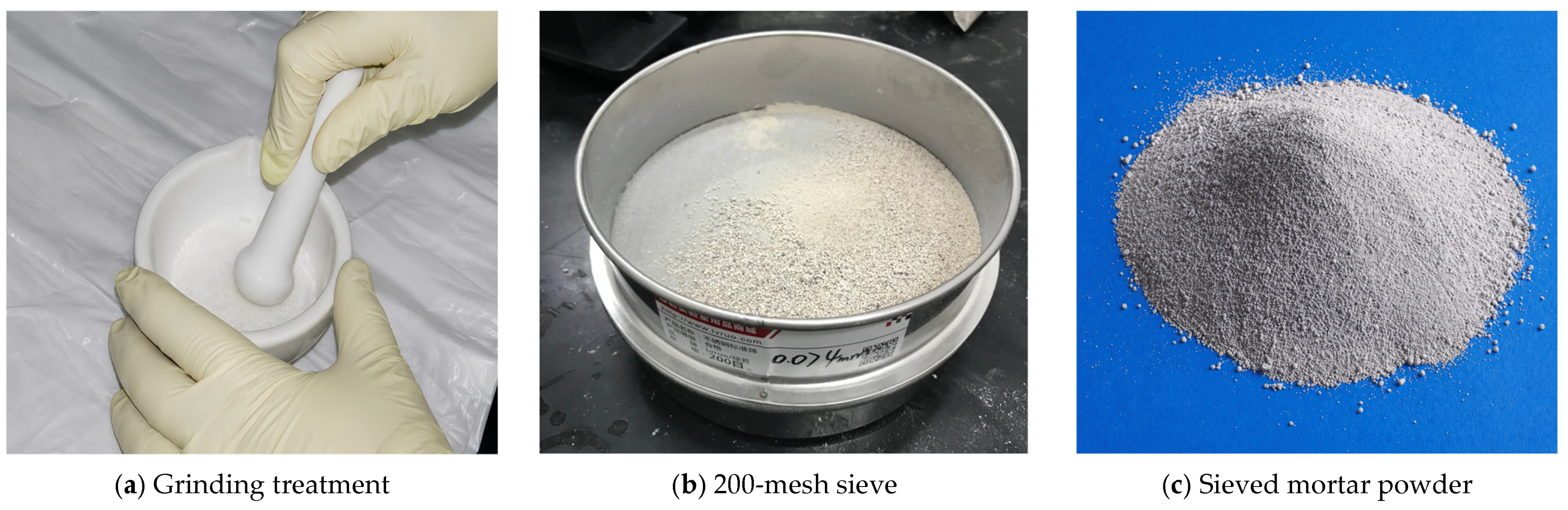
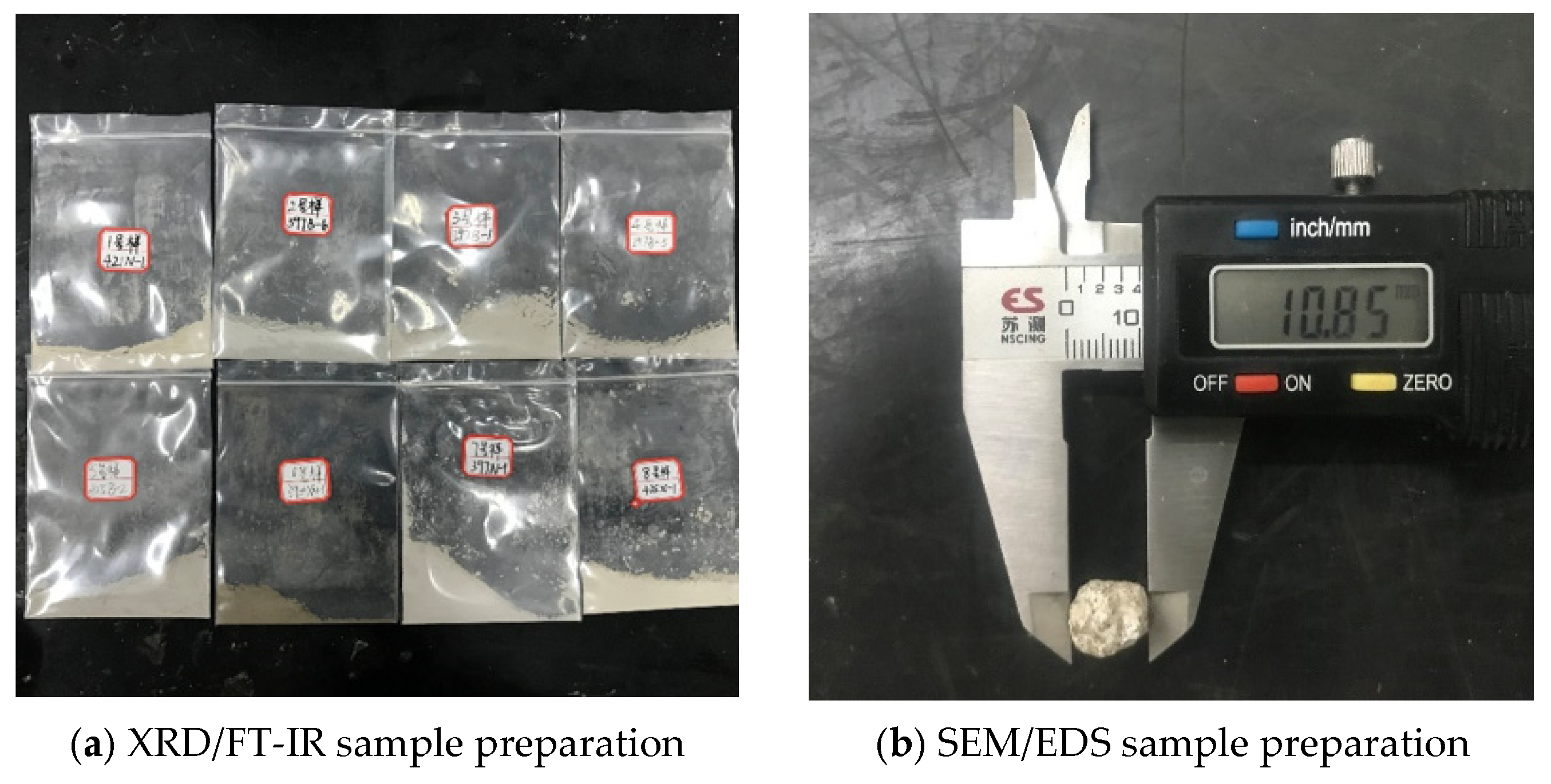
After sampling, the hardened mortar samples to be tested was dried to constant mass in a vacuum oven at 50 °C. The dried samples were placed in sealed bags, cooled to room temperature, then crushed into small particles, and thoroughly ground in a mortar. Finally, the powders were passed through a 200-mesh (approximately 80 μm) square-hole sieve. The pretreatment procedure is shown in
Figure 2. The sieved powders were labeled and sealed for subsequent XRD and FT-IR tests.
Samples for SEM/EDS testing were cut from the specimen surface or the internal cross-section, with an observation area of approximately 1 cm
2. During sampling, the original morphology of the corrosion products was preserved as much as possible to avoid excessive damage to the surface structure. After drying, the observation surfaces were sputter-coated with gold to improve electrical conductivity and reduce charge accumulation during testing. The sample preparation for microscopic characterization tests is shown in
Figure 3.
2.4.2. Sampling and Preparation of Samples for Soluble SO42− Content Testing
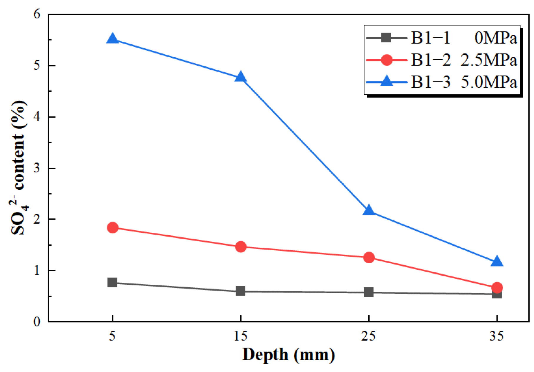
To support the analysis of sulfate ingress characteristics in mortar under different water pressure conditions, specimens from groups B1-1, B1-2, and B1-3 without limestone powder were selected for supplementary soluble SO42− content measurements. This test was used as a supplementary analysis. Because it was mainly intended to support the interpretation of sulfate ingress characteristics under different water pressure conditions, only one representative cubic specimen with dimensions of 70.7 mm × 70.7 mm × 70.7 mm was selected from each group, and the soluble SO42− content was measured only at 60 d of corrosion exposure to characterize the preliminary distribution of sulfate within the mortar under different water pressure conditions. Except that the exposure mode for the specimens used for SO42− content measurement was adjusted to one-dimensional sulfate exposure, the remaining corrosion conditions were kept consistent with the corresponding test groups, thereby ensuring comparability of the results under different water pressure conditions. Since only one representative specimen was used for each group in this test, the results were used mainly as supplementary evidence supporting the promoting effect of water pressure on sulfate ingress and were not used for statistical analysis.
To restrict the corrosion process to a single direction, four opposing side surfaces among the six surfaces of each cubic specimen were coated with Vaseline before exposure, leaving only two opposite exposed surfaces in contact with the sulfate solution. After 60 d of corrosion under the corresponding conditions, the specimens were removed and split along the exposure direction for subsequent layered sampling analysis.
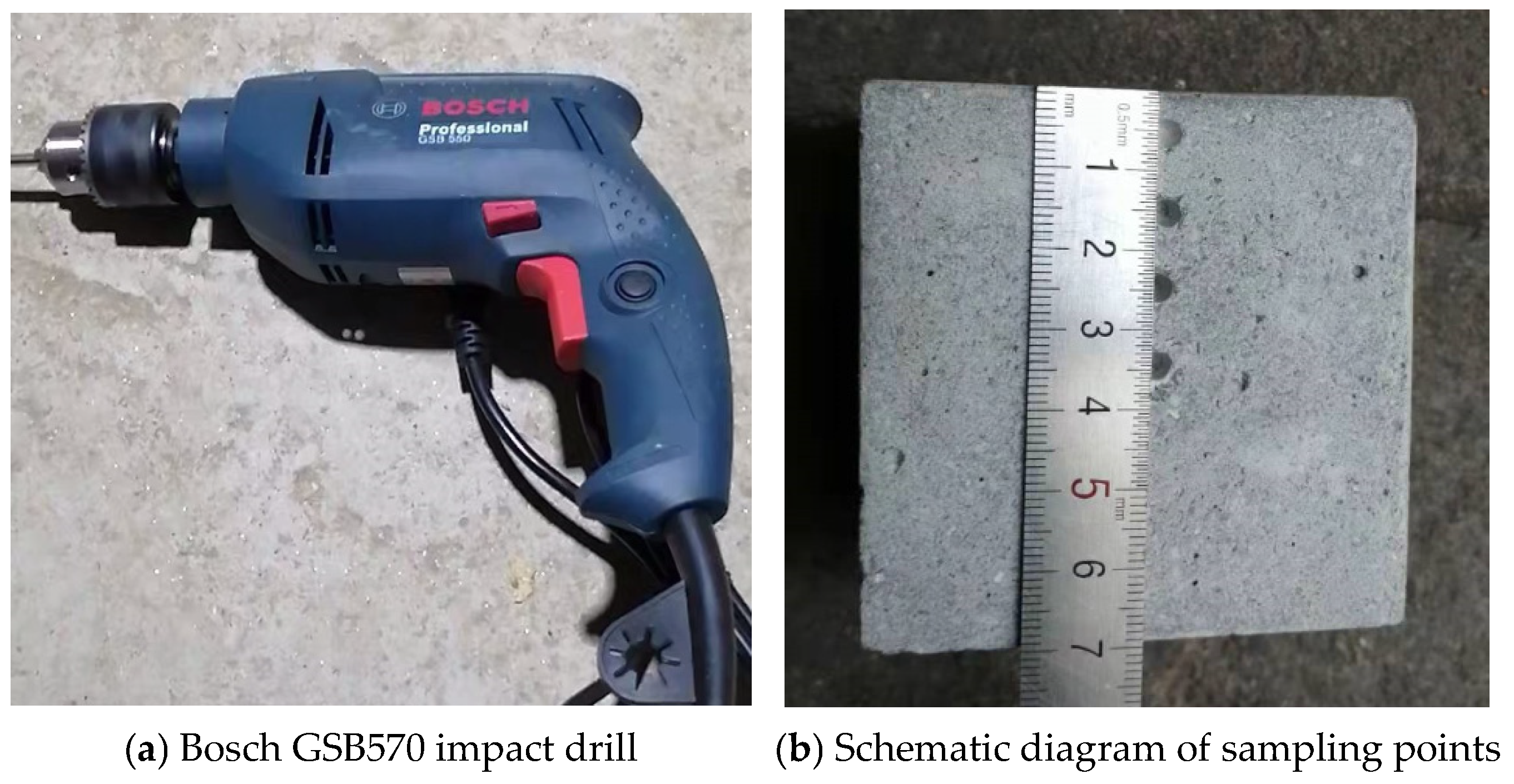
After splitting the specimens, powder samples were collected by drilling at different depths along the exposure direction using an impact drill, as shown in
Figure 4. The sampling depths from the exposed surface were 5 mm, 15 mm, 25 mm, and 35 mm, which were used to characterize the distribution of sulfate ions along the ingress direction. To ensure sampling accuracy, a Bosch GSB570 impact drill and a four-flute 3 mm drill bit (Stuttgart, Germany) were used. The obtained powder samples were labeled and stored in sealed bags. Subsequently, the samples were ground in a mortar and passed through a 200-mesh sieve to remove larger quartz sand particles and improve sample homogeneity.
2.5. Testing Methods and Data Processing
2.5.1. Compressive Strength
The compressive strength of mortar specimens was determined in accordance with the Chinese standard JGJ/T 70-2009 (Standard for Test Method of Basic Properties of Construction Mortar) [
31]. Tests were conducted using an electro-hydraulic servo testing machine on cube specimens (70.7 mm). The compressive strength was calculated by dividing the failure load by the loaded area and applying a correction factor of 1.35.
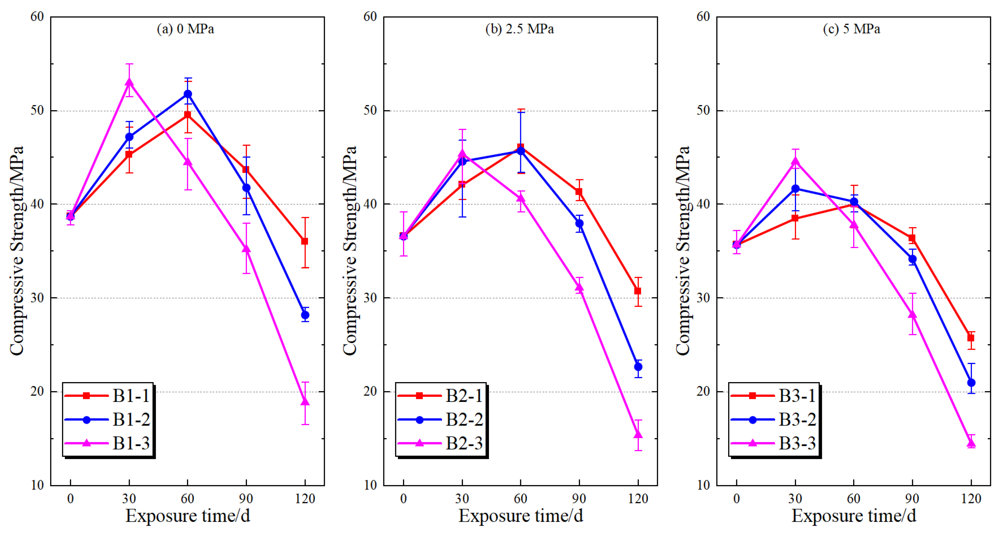
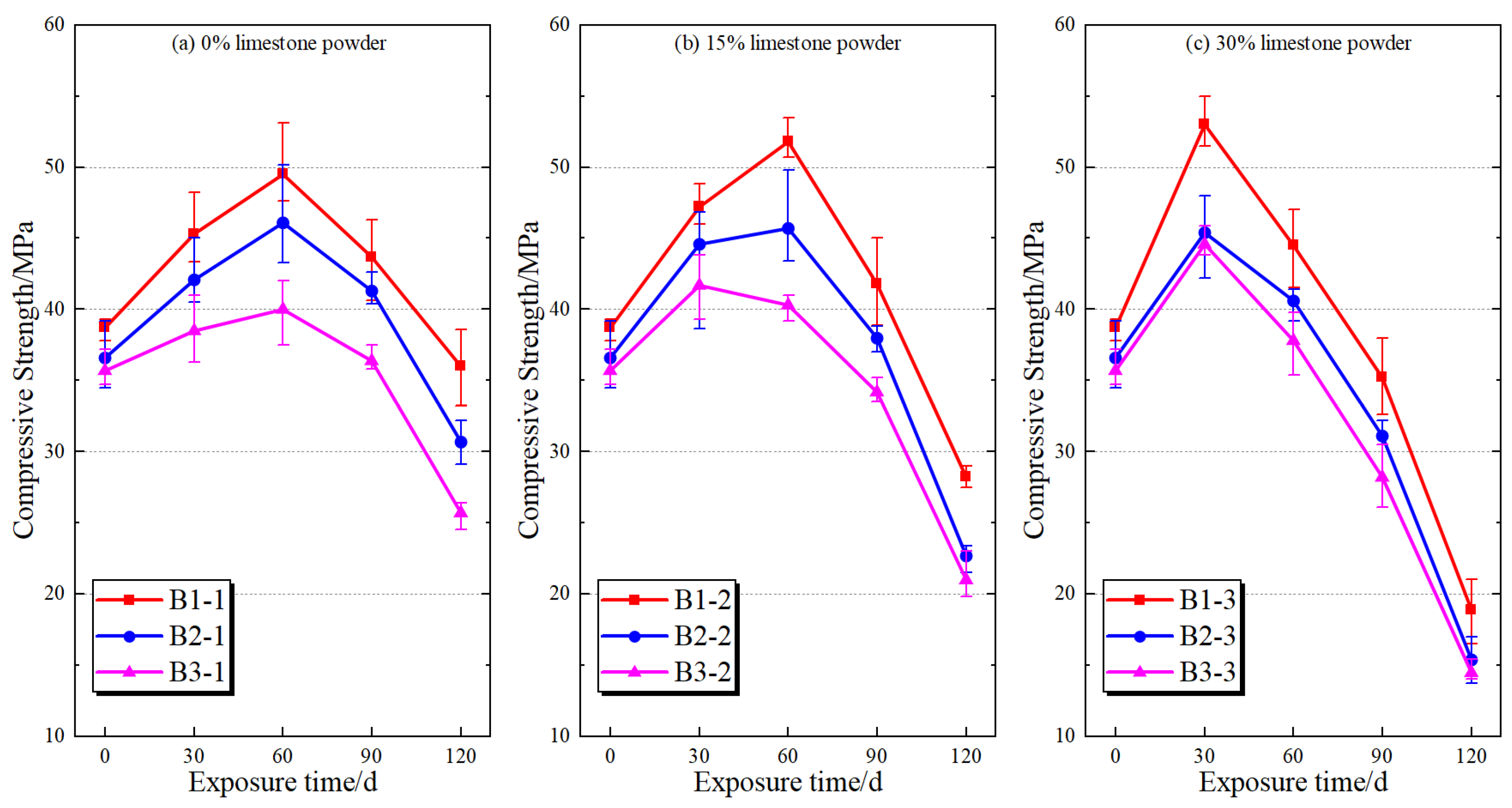
Compressive strength tests were conducted for each group at exposure ages of 30 d, 60 d, 90 d, and 120 d. Three replicate specimens were used for each test condition. Error bars in the compressive strength figures represent the dispersion of the three replicate test results. To compare the effects of limestone powder content and water pressure on compressive strength, two-way analysis of variance (two-way ANOVA) was performed using the raw compressive strength data from the three replicate specimens at each exposure age, with the interaction between the two factors included in the model. Statistical significance was accepted at p < 0.05, and the effect size was expressed using ηp2 (partial eta squared). All statistical analyses were performed using Python 3.10 with the scipy and statsmodels packages.
2.5.2. Observation of Macroscopic Deterioration Morphology
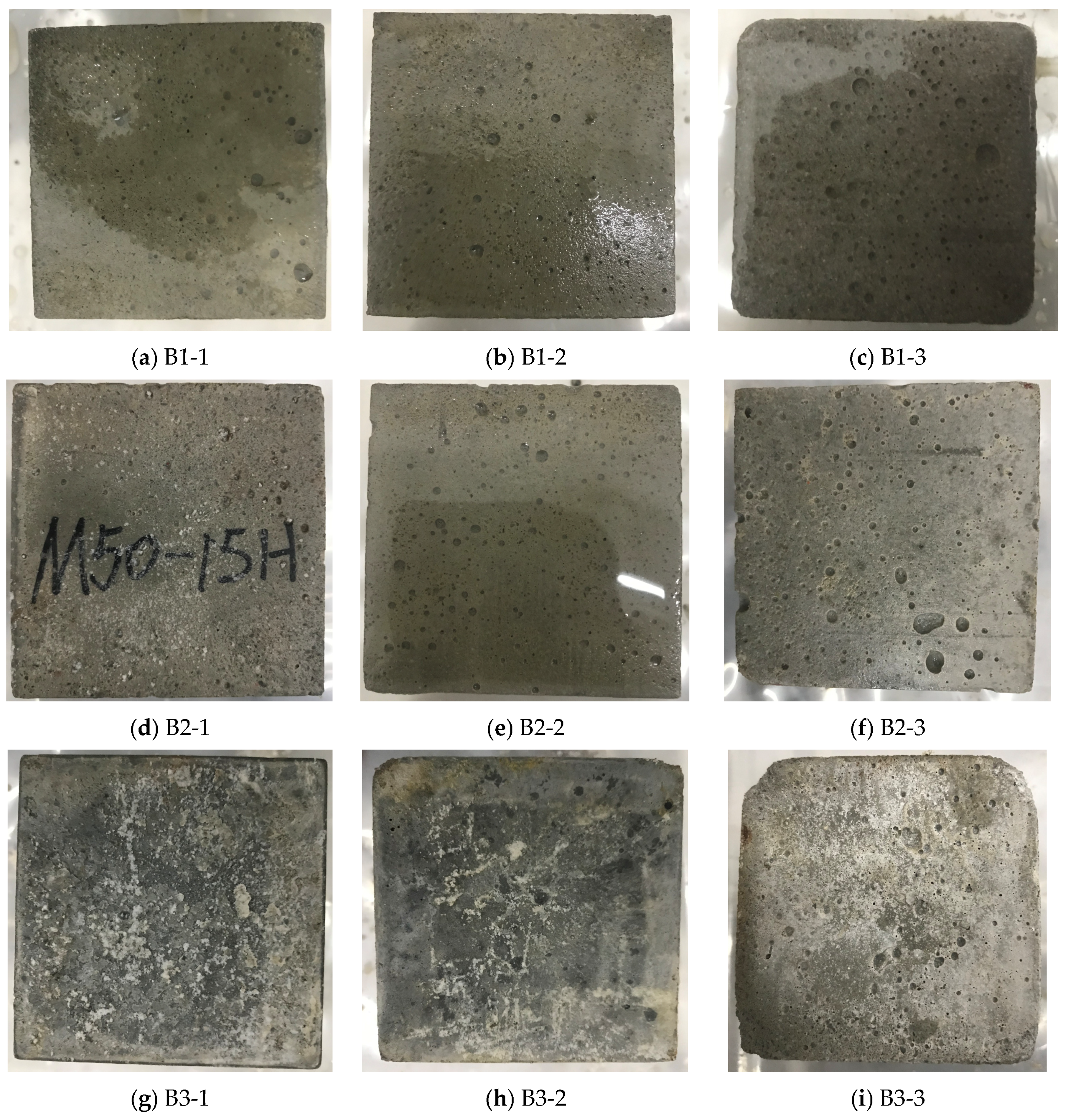
After reaching the specified exposure ages, the specimen surfaces were cleaned and photographed to record their apparent deterioration characteristics. The observations mainly included changes in surface color, surface roughening, localized peeling, softening, argillization, and corner damage. These observations were used mainly to characterize the evolution of surface damage and to correlate the macroscopic deterioration with changes in compressive strength and microstructural characterization results.
2.5.3. X-Ray Diffraction (XRD) Testing
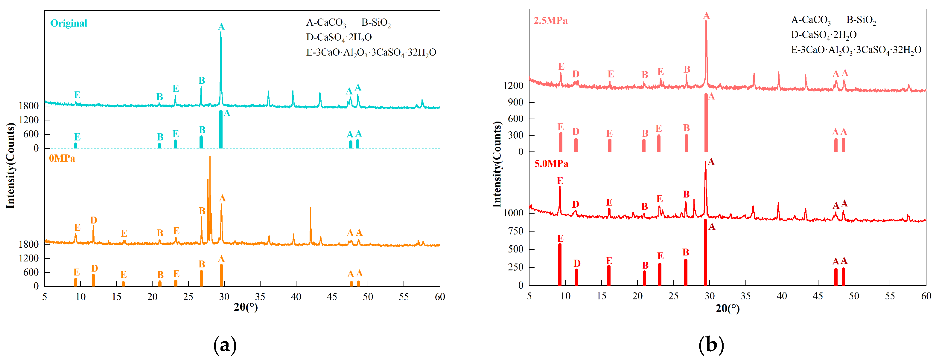
XRD analysis was performed using a D8 ADVANCE diffractometer (Bruker, Karlsruhe, Germany), with an angular reproducibility of ±0.0001° and a scanning range of 3–105° (2θ). XRD was mainly used to identify the phase composition of mortar corrosion products under different exposure conditions and to analyze the influence of water pressure and limestone powder content on the evolution of the main corrosion phases. Considering that some diffraction peaks of ettringite and thaumasite overlap, the XRD results were used mainly as preliminary evidence for phase identification and were further interpreted in combination with FT-IR and SEM/EDS results.
2.5.4. Fourier-Transform Infrared Spectroscopy (FT-IR) Testing
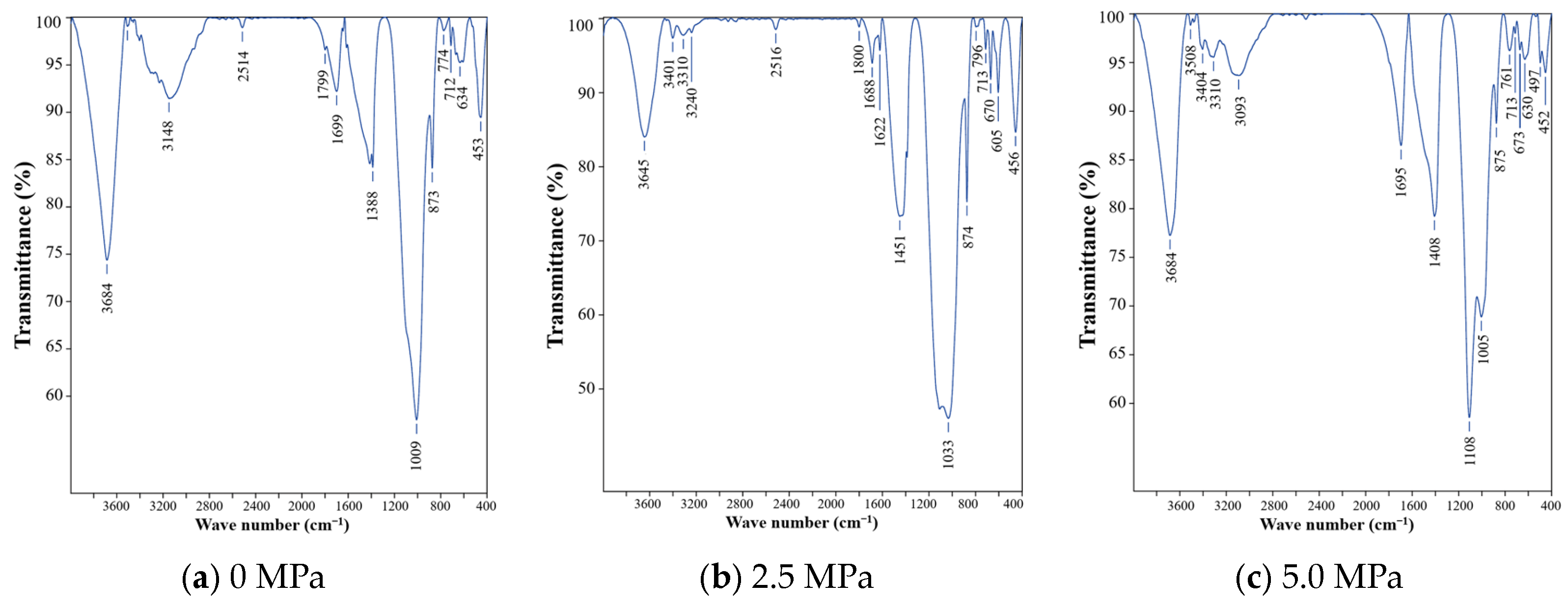
FT-IR analysis was conducted using a VERTEX 80v spectrometer (Bruker, Karlsruhe, Germany), with a spectral range of 8000–350 cm−1 and a resolution of 0.06 cm−1. FT-IR was mainly used to identify characteristic functional groups in the corrosion products and, together with XRD results, to support the analysis of the formation characteristics of ettringite, thaumasite, and other related corrosion products.
2.5.5. Scanning Electron Microscopy and Energy-Dispersive Spectroscopy (SEM/EDS)
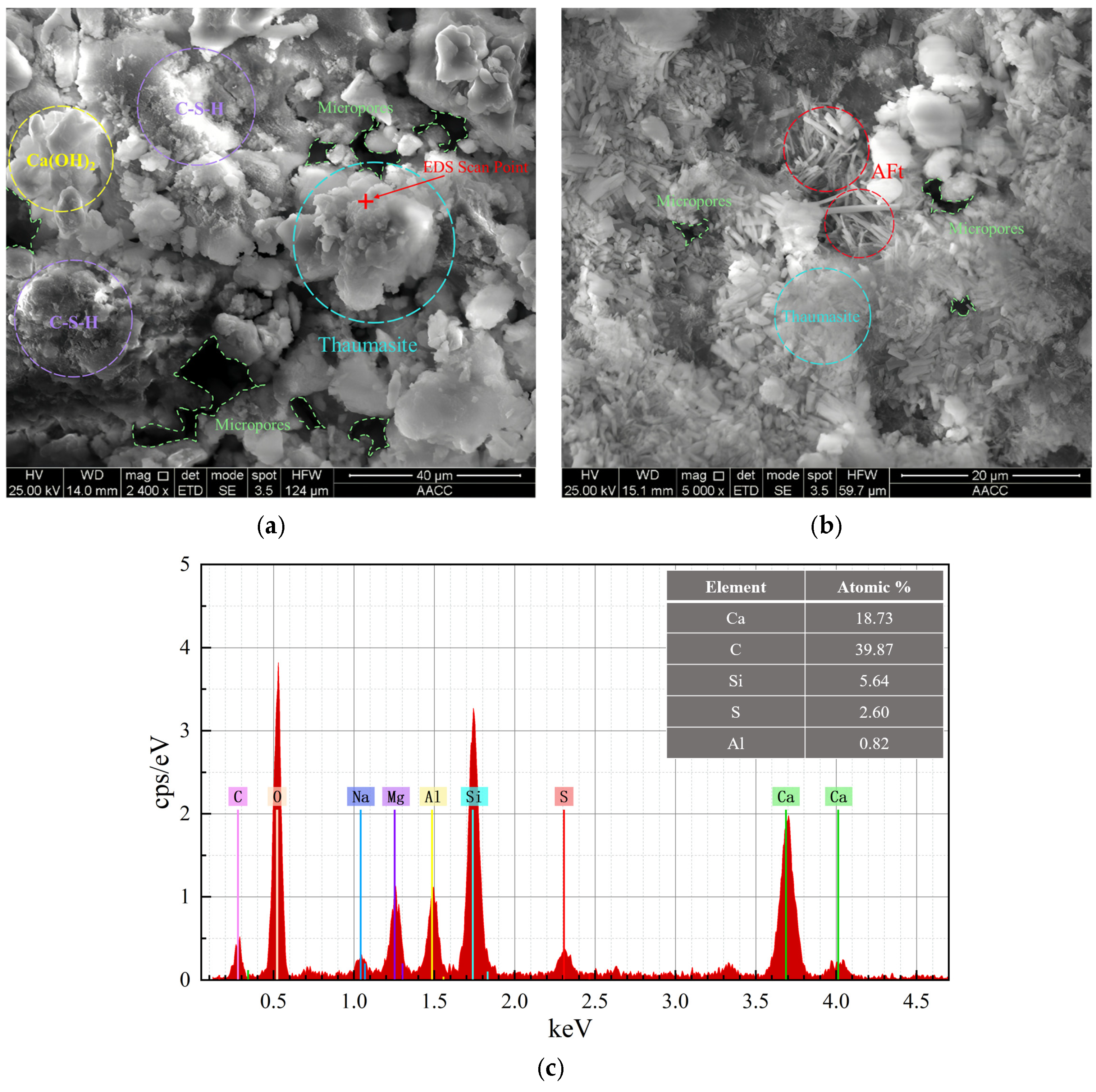
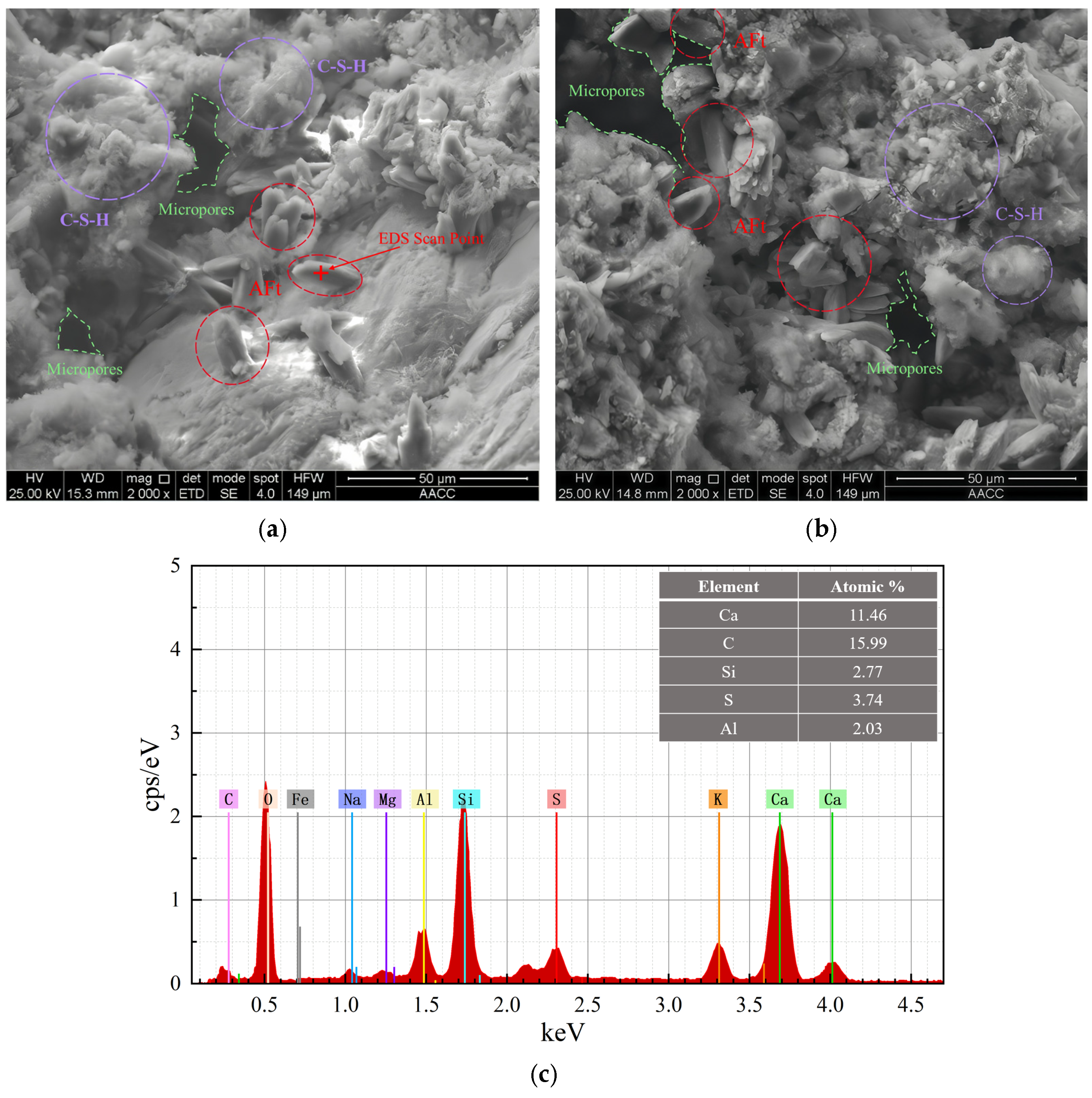
The microstructure and elemental composition of corrosion products were analyzed using a Quanta 250 scanning electron microscope (FEI, Hillsboro, OR, USA) equipped with an EDS system. SEM was mainly used to observe the micromorphological features of the corrosion products, while EDS was used to obtain the elemental composition of the corresponding regions and thereby support the interpretation of the spatial distribution of different corrosion products. Considering that XRD, FT-IR, and SEM/EDS provide mainly qualitative or semi-quantitative evidence in this study, these results were used to support the analysis of corrosion product types and their distribution characteristics rather than for rigorous quantitative phase composition calculations.
2.5.6. Determination of Soluble SO42− Content
The soluble SO
42− content was determined in accordance with the Chinese standard GB/T 11899-1989 (Water Quality—Determination of Sulfate—Gravimetric Method) [
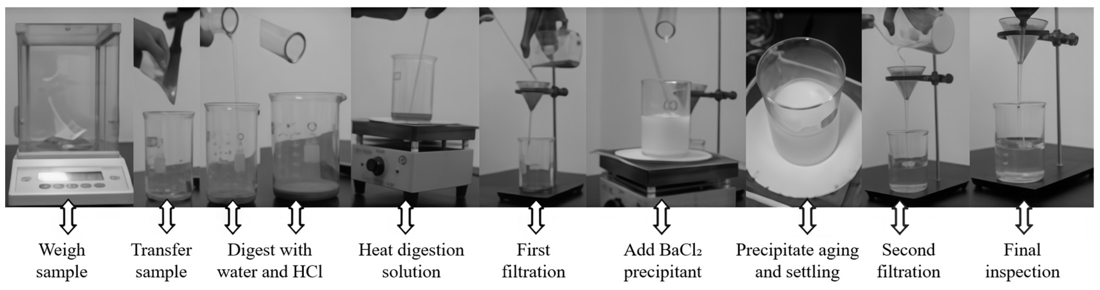
32]. The specific procedure was as follows. First, the weighed mortar powder was placed in a beaker, and 10 mL of hydrochloric acid and 35 mL of distilled water were added. The mixture was heated to boiling to remove CO
32− from the sample and fully dissolve soluble SO
42−. The slurry was then filtered and washed. The filtrate was made up to 200 mL, and 10 mL of 10 vol% BaCl
2 solution was added to precipitate SO
42− as BaSO
4. After standing for more than 4 h, the solution was filtered again. During washing, 1 vol% AgNO
3 solution was used to check whether Cl
− remained in the filtrate until no white flocculent precipitate formed. The filter paper containing the precipitate was then placed together with the crucible in a high-temperature furnace for ignition and ashing. After cooling, the mass of the crucible and the total mass of the crucible and precipitate were weighed.
Figure 5 shows the procedure for soluble SO
42− content determination. The soluble SO
42− content in the sample was calculated according to the conversion relationship between BaSO
4 precipitate mass and SO
42−.
Here,
m is the mass of the weighed powder sample, g;
m1 is the mass of the crucible, g; and
m2 is the total mass of the precipitate and crucible, g. The test results were used to obtain the SO
42− content distribution at different depths and to support the interpretation of the influence of water pressure on sulfate ingress characteristics.
4. Discussion
The above results on macroscopic performance, depth-dependent soluble SO42− content distribution, and microstructural characteristics indicate that water pressure and limestone powder content jointly affect the deterioration process of cement mortar in a sulfate environment. To avoid overinterpreting the experimental results as direct proof of the mechanism, this section discusses the internal relationships among the experimental observations from the perspectives of water pressure, limestone powder, their coupled effect, environmental interactions, and study limitations.
4.1. Effect of Water Pressure on Sulfate Ingress and Damage Development
Water pressure is an important external factor affecting sulfate ingress and the deterioration rate of mortar. Compared with atmospheric immersion, elevated water pressure can increase the likelihood that the external sulfate solution enters pores, interfacial transition zones, and pre-existing microdefects, thereby increasing the opportunity for sulfate ions to contact and react with cement hydration products. In this study, the depth-dependent soluble SO
42− content distribution of the B1-series specimens shows that the SO
42− content at different depths inside the specimens generally increases with increasing water pressure, providing direct chemical evidence that water pressure promotes sulfate ingress. This interpretation is generally consistent with recent studies that describe external sulfate attack as a coupled process involving ion transport, chemical reactions, and damage development [
4].
The compressive strength results also show that higher water pressure leads to more pronounced later-stage strength loss. Under elevated water pressure, early corrosion products may fill part of the pore space, resulting in a temporary increase in strength. However, as exposure proceeds, the continuous formation of corrosion products and the crystallization stress induced by them gradually exceed the beneficial effect of pore filling, leading to strength loss and aggravated surface damage.
It should be noted that crack width, crack number, porosity, permeability coefficient, and water absorption were not directly measured in this study. Therefore, the discussion on the role of water pressure in promoting sulfate ingress and damage development should be understood as a mechanistic interpretation based on the existing macroscopic performance, apparent morphology, and SO42− content distribution results, and it still needs to be verified with further pore structure and permeability tests. Future studies may use μCT, MIP, crack image analysis, and permeability testing to further quantify the evolution of the pore–crack structure under water pressure.
4.2. Effect of Limestone Powder on TSA Deterioration
The influence of limestone powder on TSA deterioration is mainly reflected in two aspects. First, limestone powder can provide a carbonate source for the system, and carbonate is one of the important components required for thaumasite formation [
26,
28]. In this study, with increasing limestone powder content, the surface argillization of the specimens becomes more obvious, and the FT-IR characteristic absorptions related to CO
32− and [SiO
6] structures become more pronounced. This indicates that limestone powder increases the possibility of forming thaumasite-rich products. This interpretation is consistent with recent studies indicating that limestone powder may increase the susceptibility of cementitious materials to thaumasite-related deterioration by providing carbonate availability under favorable sulfate exposure conditions [
26,
33].
Second, limestone powder, as a low-reactivity or inert filler, may alter the pore structure and interfacial characteristics of the mortar matrix. Previous studies have shown that a higher limestone powder content may increase the proportion of capillary pores and connected pores, thereby affecting ion migration and permeation behavior [
26,
34,
35]. Under elevated water pressure, such structural characteristics may further amplify the ingress of sulfate solution into the mortar matrix and thus intensify later-stage strength loss.
It should be noted that pore structure parameters were not directly measured in this study. Therefore, the discussion on limestone powder-induced changes in pore connectivity is mainly based on the existing literature and the integrated interpretation of strength, morphology, and microstructural product changes observed in this test. To further clarify the influence of limestone powder on transport pathways, future work may combine MIP, low-field nuclear magnetic resonance, water absorption, and permeability tests for verification.
4.3. Coupled Effect of Water Pressure and Limestone Powder
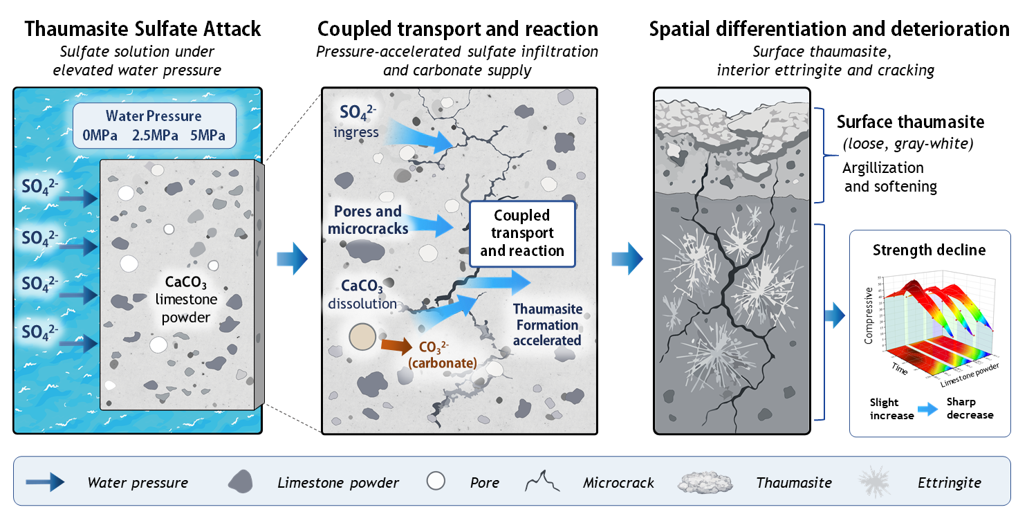
The results of this study indicate that water pressure and limestone powder do not affect TSA deterioration in isolation, but act jointly at both the transport and reaction levels. From the transport perspective, elevated water pressure promotes the ingress of sulfate solution into mortar. From the reaction perspective, limestone powder increases carbonate availability and provides material conditions for the formation of thaumasite-related products. When the two factors are present simultaneously, sulfate supply and carbonate supply are more likely to be coupled in the surface region, thereby accelerating surface softening and argillization. The two-way ANOVA results show that, at an exposure age of 120 d, the interaction between water pressure and limestone powder content has a significant effect on compressive strength, supporting from the macroscopic performance perspective that the two factors jointly affect later-stage deterioration of mortar. Based on this, the coupled effect is further interpreted through a pathway of “transport enhancement–carbonate supply–corrosion product evolution–aggravated macroscopic damage”. This interpretation is consistent with recent reviews describing sulfate deterioration as a coupled transport–reaction–damage process, while the present study further highlights the combined role of water pressure-assisted sulfate supply and limestone-powder-derived carbonate availability [
4,
5].
Recent studies conducted under atmospheric or low-pressure sulfate exposure conditions have shown that TSA in carbonate-bearing cementitious materials is strongly governed by temperature, moisture availability, and carbonate supply. Wang et al. reported that, under low-temperature sulfate exposure, mortars containing limestone powder suffered TSA-related deterioration after long-term exposure, with strength losses of 17.4–48.7% after 360 d, whereas thaumasite was not detected in specimens without limestone powder [
33]. Beltrame et al. also found that thaumasite formation in Portland limestone cement mortars was more pronounced under continuous immersion than under wetting/drying cycles, indicating that sustained moisture supply and ion transfer are important for TSA development [
36]. In addition, Song and Ma observed long-term TSA in carbonate-bearing mortars exposed to Na
2SO
4 solution at low temperature, further confirming the sensitivity of TSA to carbonate availability and exposure conditions [
29]. Compared with these atmospheric or low-pressure studies, the present results indicate that elevated water pressure may further accelerate TSA deterioration by promoting sulfate ingress and expanding the affected depth. Therefore, the coupled deterioration observed in this study is not only associated with limestone powder-derived carbonate availability, but also with water pressure-assisted sulfate transport, which distinguishes it from conventional immersion-based TSA deterioration.
From the perspective of possible transport pathways, the incorporation of limestone powder increases the carbonate source in the system and may also change the pore structure and connectivity of the mortar matrix. Since limestone powder mainly exists as filler particles, partial replacement of cement reduces the cement clinker content and the amount of hydration products formed, which may decrease matrix compactness and provide more favorable pathways for external sulfate solution to enter the mortar. Under elevated water pressure, the external sulfate solution is more likely to migrate inward along surface pores, interfacial transition zones, and pre-existing defects, thereby increasing the contact opportunity between sulfate and hydration products. This interpretation is consistent with the soluble SO42− content test results, which show that the SO42− content at different depths inside the mortar generally increases with increasing water pressure, indicating that water pressure promotes sulfate ingress.
From the perspective of reaction conditions, the carbonate source provided by limestone powder and the continuous sulfate supply promoted by water pressure jointly create a favorable environment for the formation of thaumasite-related products. Thaumasite formation requires the participation of sulfate, carbonate, calcium, and silicon sources. Therefore, sulfate ingress alone or carbonate supply alone is insufficient to fully explain the severe surface argillization observed under conditions of elevated water pressure and high limestone powder content. Under the present test conditions, elevated water pressure may enhance the migration ability of SO42− within the mortar, while higher limestone powder content increases the availability of CO32−. The combined action of these two factors makes the formation of thaumasite-rich corrosion product assemblages more likely in the surface region.
This coupled effect is ultimately manifested as aggravated macroscopic deterioration. Early corrosion products may fill part of the pores, causing a temporary increase in compressive strength. However, as exposure time increases, sulfate reaction products continue to form. Thaumasite-rich, mud-like products at the surface weaken the cementing ability of the matrix, while ettringite-rich products in the interior may generate expansive stress and induce structural damage. Therefore, under the combined action of elevated water pressure and high limestone powder content, mortar exhibits more severe surface softening, peeling, and strength loss. In other words, limestone powder mainly provides the material basis for TSA development, whereas water pressure mainly enhances the ingress of aggressive media and the reaction conditions. The two factors jointly amplify the deterioration process of mortar.
Therefore, this study suggests that water pressure and limestone powder do not simply affect TSA independently, but may form a coupled effect through a pathway of “transport enhancement–carbonate supply–corrosion product evolution–aggravated macroscopic damage”. Nevertheless, this mechanism remains a mechanistic interpretation based on the existing macroscopic performance, SO42− content distribution, and microstructural characterization results, and further verification using pore structure testing, permeability testing, and quantitative phase analysis is still required.
4.4. Environmental Interactions and Engineering Implications
In real deep underground environments, sulfate attack is usually controlled by multiple environmental factors, including sulfate concentration, water pressure, temperature, groundwater renewal rate, ion supply from surrounding rock or soil, pH conditions, and long-term loading state. In this study, a 10 wt% Na2SO4 solution, a low-temperature exposure environment of approximately (12 ± 5) °C, and water pressures of 0–5.0 MPa were used mainly to highlight the effects of water pressure and limestone powder content on TSA deterioration.
From an engineering perspective, deep shaft lining concrete is usually exposed for a long time to sulfate-rich groundwater and elevated water pressure. If the material system contains a relatively high carbonate source, the risk of TSA-related deterioration may increase. The results of this study suggest that, in elevated water pressure sulfate environments, attention should be paid to the coupling among material composition, pore structure, external water pressure, and ion supply, rather than inferring the service behavior of deep engineering structures solely from sulfate attack mechanisms obtained under atmospheric immersion conditions. For cement-based materials containing limestone powder or a high carbonate source, the risk of transport–reaction coupling under elevated water pressure should be given particular attention.
However, real groundwater is usually a multi-ion system, and temperature, pressure, and flow conditions vary with time and space. The present test used a single Na2SO4 solution and controlled water pressure conditions, which cannot fully represent actual service environments. Therefore, future studies should further consider the combined action of multiple ions such as Mg2+, Cl−, and HCO3−, as well as the effects of temperature fluctuation, long-term seepage, and stress coupling on the TSA deterioration process.
4.5. Study Limitations
This study analyzed TSA deterioration under the coupled effects of elevated water pressure and limestone powder using compressive strength, macroscopic morphology, depth-dependent soluble SO42− content distribution, XRD, FT-IR, and SEM/EDS results. To clarify the scope of applicability of the conclusions, the following limitations should be noted.
First, the soluble SO42− content test was conducted only on representative B1-series specimens at 60 d and was mainly used to support the interpretation of the influence of water pressure on sulfate ingress. It cannot be regarded as a complete quantitative description of sulfate transport behavior for all mixture proportions and all exposure ages.
Second, XRD, FT-IR, and SEM/EDS analyses were mainly conducted on representative samples. In particular, SEM/EDS analysis was mainly performed on representative surface and internal regions of B3-series specimens exposed to 5.0 MPa for 120 d, which showed relatively severe deterioration. Therefore, the interpretation of thaumasite-rich surface assemblages and ettringite-rich internal assemblages should be understood as a comprehensive qualitative result based on multiple characterization methods under representative conditions and should not be directly generalized as a quantitative rule for all test groups.
Finally, MIP, μCT, quantitative crack width analysis, permeability or water absorption tests, and Rietveld quantitative phase analysis were not conducted in this study. Therefore, the discussion on pore structure changes and the transport–damage coupling process remains a mechanistic interpretation. Future studies may further combine pore-structure characterization, seepage properties, and quantitative phase analysis to improve the understanding of the transport–reaction–damage mechanism of TSA under elevated water pressure.