1. Introduction
Traditional brick masonry buildings in China are commonly constructed using fired clay grey bricks bonded with glutinous rice mortar, forming a unique masonry system with significant historical and cultural value. However, long-term environmental deterioration, material degradation, and seismic actions may induce cracking, surface weathering, deformation, and local instability, thereby compromising the structural integrity and load-bearing capacity of these historic structures. Previous seismic investigations have demonstrated that masonry-based historic structures are vulnerable to severe damage under earthquake loading [
1,
2].
Fiber-reinforced polymer (FRP) composites have been increasingly applied for strengthening masonry structures due to their high strength-to-weight ratio, corrosion resistance, and convenient installation, showing great potential for the conservation of historic masonry buildings [
3,
4]. Among various FRP materials, carbon fiber-reinforced polymer (CFRP) sheets are widely used owing to their high elastic modulus, excellent tensile strength, and favorable deformation compatibility [
5,
6,
7]. However, the effectiveness of CFRP strengthening systems is largely governed by the interfacial bond behavior between CFRP sheets and masonry substrates. Interfacial debonding often occurs before the tensile capacity of FRP sheets is fully mobilized and represents a critical failure mode of FRP-strengthened masonry structures [
8,
9]. Compared with concrete, masonry is a heterogeneous composite material composed of bricks, mortar, and brick–mortar interfaces, resulting in complex stress transfer and crack propagation mechanisms at FRP–masonry interfaces. Moreover, traditional glutinous rice mortar differs significantly from modern cement-based mortars in composition, microstructure, and mechanical properties, leading to uncertainties regarding its interfacial bond behavior. Recent studies have also shown that bio-additives can influence the morphology and performance of lime-based mortars [
10]. Compared with conventional cement-based mortar, glutinous rice mortar generally exhibits lower stiffness and strength but relatively better deformation compatibility with traditional fired clay grey bricks, which may affect the stress transfer and debonding behavior of the CFRP–masonry interface. Therefore, understanding the bond behavior between CFRP sheets and grey brick masonry bonded with glutinous rice mortar is essential for developing reliable strengthening methods for traditional masonry structures.
Extensive studies have investigated the interfacial behavior of FRP-strengthened concrete and masonry structures. For FRP–concrete interfaces, Chajes et al. [
11] characterized the interfacial stress transfer mechanism through single-shear tests. With the application of FRP strengthening to masonry substrates, various experimental methods, including single-shear and double-shear tests, have been adopted to evaluate load–slip responses, failure modes, effective bond length, and interfacial stress distribution. Among them, double-shear tests have been widely used because of their symmetric loading configuration and reduced eccentricity effects. Valluzzi et al. [
12] compared different shear test configurations and provided comprehensive experimental data regarding the bond behavior of FRP-strengthened masonry interfaces.
European researchers have also made important contributions to the strengthening of masonry structures using externally bonded composite systems. For example, brick masonry vaults strengthened with FRP laminates have been investigated by Valluzzi, Valdemarca, and Modena, showing that the strengthening effectiveness of FRP systems is closely related to the bond behavior and failure mechanism of the masonry–reinforcement system [
13]. In addition to organic-matrix FRP systems, mortar-based composite systems have been widely investigated in Europe. De Felice et al. reviewed mortar-based systems for externally bonded strengthening of masonry and emphasized the importance of reinforcement–masonry compatibility, substrate properties, and interfacial behavior in strengthened masonry structures [
14]. Moreover, studies on ceramic and clay brick masonry walls have shown that reinforcement arrangement can influence the strength and deformability of masonry walls. Jasiński investigated the influence of bed-joint reinforcement on the strength and deformability of masonry shear walls, indicating that masonry-unit characteristics and reinforcement configuration are important factors affecting wall behavior [
15].
Although CFRP/epoxy systems have been widely used for masonry strengthening, their performance may be affected by temperature because of the organic polymer matrix. For masonry strengthening applications where thermal performance and material compatibility are of particular concern, inorganic composite systems, such as fabric-reinforced cementitious matrix (FRCM) or inorganic-matrix composite systems, have also been investigated as alternative strengthening solutions [
14,
16].
The influence of bond geometry parameters, particularly bond width and bond length, has also attracted considerable attention. Chen and Teng [
17] developed anchorage strength models for FRP and steel plates bonded to concrete and investigated factors affecting interfacial capacity. Rotunno et al. [
18] demonstrated that bonded area significantly influences the ultimate load, load–displacement response, and failure modes of CFRP-strengthened masonry specimens. Chen and Teng [
19] further provided a comprehensive collection of studies on FRP bond behavior, including the effects of material properties and bond characteristics. In addition to FRP properties and geometric parameters, masonry substrate characteristics play an important role in interfacial behavior. Aiello and Sciolti [
20] and Mazzotti and Murgo [
21] highlighted the influence of mortar joints on interfacial stress transfer and debonding mechanisms. Carloni and Subramaniam [
22,
23] further revealed the influence of mortar joints on stress distribution during debonding. Ghiassi et al. [
24] demonstrated the importance of considering mortar joints and masonry heterogeneity in FRP-strengthened masonry analysis, while Faella et al. [
25] investigated the influence of masonry characteristics on FRP bond behavior. Jin et al. [
26] studied the bond behavior of CFRP–clay brick interfaces using double-shear tests and obtained corresponding load–slip responses and failure characteristics. Nevertheless, most existing studies have focused on conventional clay bricks, cement-based mortar masonry, or stone masonry, while the interfacial behavior of traditional grey brick masonry bonded with glutinous rice mortar remains insufficiently understood.
Numerical investigations of FRP interfaces have mainly focused on bond–slip relationships, debonding prediction, and damage evolution mechanisms. Lu et al. [
8] proposed bond–slip models for FRP–concrete interfaces based on experimental and numerical studies, while Yao et al. [
27] investigated the applicability of bond–slip models for predicting debonding behavior. With the extension of numerical analyses to masonry structures, Ceroni et al. [
9], Grande and Imbimbo [
28], and Ghiassi et al. [
24] highlighted the importance of considering mortar joints and masonry heterogeneity. Interface-based numerical approaches, including cohesive zone models, have also been adopted to describe interfacial damage evolution and debonding processes. Chen et al. [
29] employed cohesive elements with a bilinear constitutive relationship to simulate FRP–masonry interface behavior, and Su et al. [
30] demonstrated that combining homogenized masonry models with interface elements can provide a reasonable balance between computational efficiency and simulation accuracy.
Overall, previous studies have established valuable experimental and numerical approaches for investigating FRP-strengthened conventional masonry systems. These studies have clarified important aspects such as test methods, failure modes, bond–slip behavior, effective bond length, stress-transfer mechanisms, and numerical simulation strategies. However, most existing bond-strength and bond–slip models have been developed or calibrated based on conventional masonry substrates, such as clay brick, stone, or cement-/lime-based masonry. For traditional grey brick masonry bonded with glutinous rice mortar, experimental evidence on CFRP–masonry interfacial bond behavior remains limited. In particular, the effects of bond geometry and local interface defects on the force–displacement response, peak load-carrying capacity, failure mode, and stress-transfer characteristics of this traditional material system are still insufficiently understood. Therefore, further experimental characterizations and experimental–numerical comparisons are needed to clarify the CFRP–masonry load-transfer characteristics of traditional grey brick masonry bonded with glutinous rice mortar.
Therefore, this study investigates the interfacial bond behavior and load-transfer characteristics of CFRP sheets bonded to grey brick masonry with glutinous rice mortar through combined experimental and numerical approaches. Different from most previous studies on CFRP-strengthened conventional masonry, this study focuses on a traditional grey brick masonry system bonded with glutinous rice mortar and examines the effects of bond length, bond width, and local interface defects on the CFRP–masonry load-transfer behavior. Double-shear tests were conducted to characterize the failure modes, force–displacement responses, and interfacial load-carrying behavior of CFRP-strengthened traditional masonry, with bond length and interface debonding ratio considered as additional interface conditions. Subsequently, a finite element model considering interface behavior was established and compared with the experimental results. Parametric analyses were further performed to clarify the influence of bond width on stress transfer, stiffness evolution, and interfacial performance. The findings provide experimental evidence and numerical reference for understanding the CFRP–masonry interfacial behavior and load-transfer characteristics of traditional grey brick masonry bonded with glutinous rice mortar.
3. Experimental Investigation
3.1. Specimen Design and Experimental Program
To investigate the interfacial bond behavior between CFRP sheets and glutinous rice mortar-bonded grey brick masonry, double-shear tests were conducted with different bond widths. By symmetrically bonding CFRP sheets on both sides of the masonry specimens and applying axial tensile loading, the force–displacement responses and failure characteristics of the CFRP–masonry interfaces were obtained.
The mechanical behavior of CFRP–masonry interfaces is affected by bond geometry and interface integrity. Therefore, different bond lengths and debonding ratios were considered in the experimental program to evaluate the influence of interface conditions on the interfacial bond behavior. In this study, bond width was selected as one representative geometric parameter controlling the effective load-transfer area. Bond length and debonding ratio were introduced as auxiliary parameters to evaluate whether the observed bond-width-related behavior was affected by different bonding conditions.
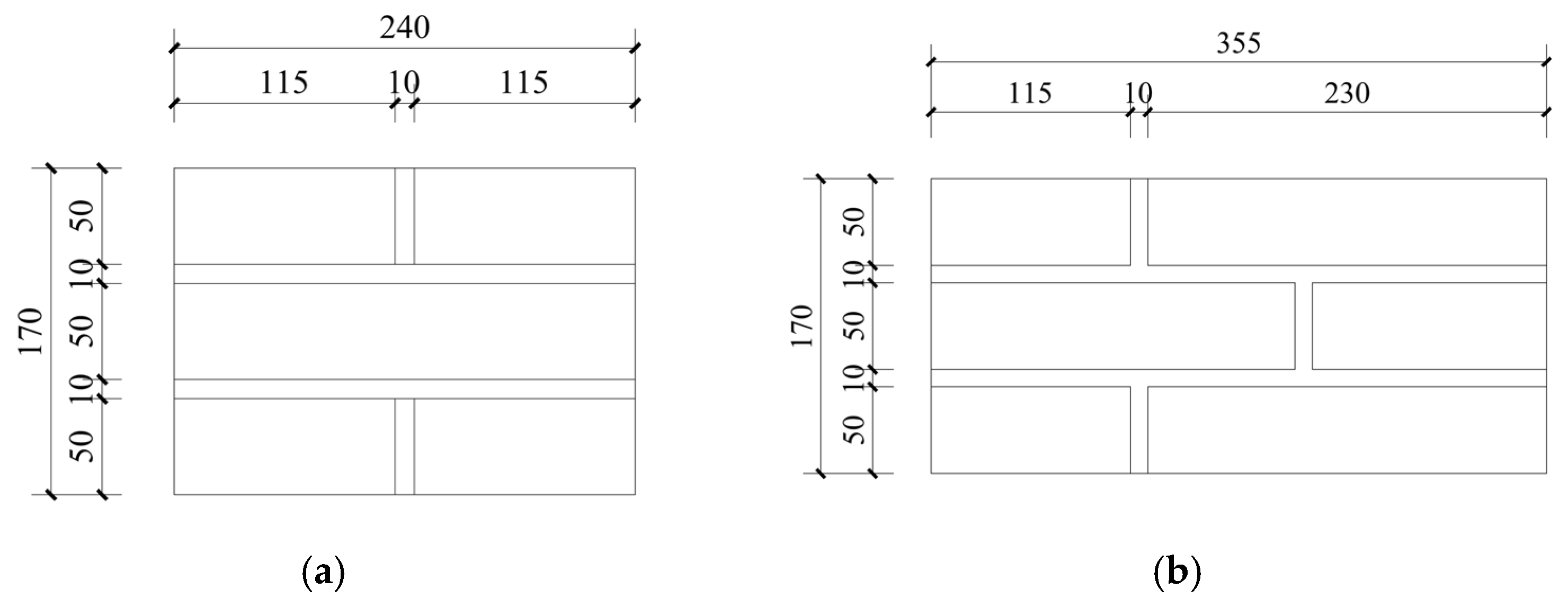
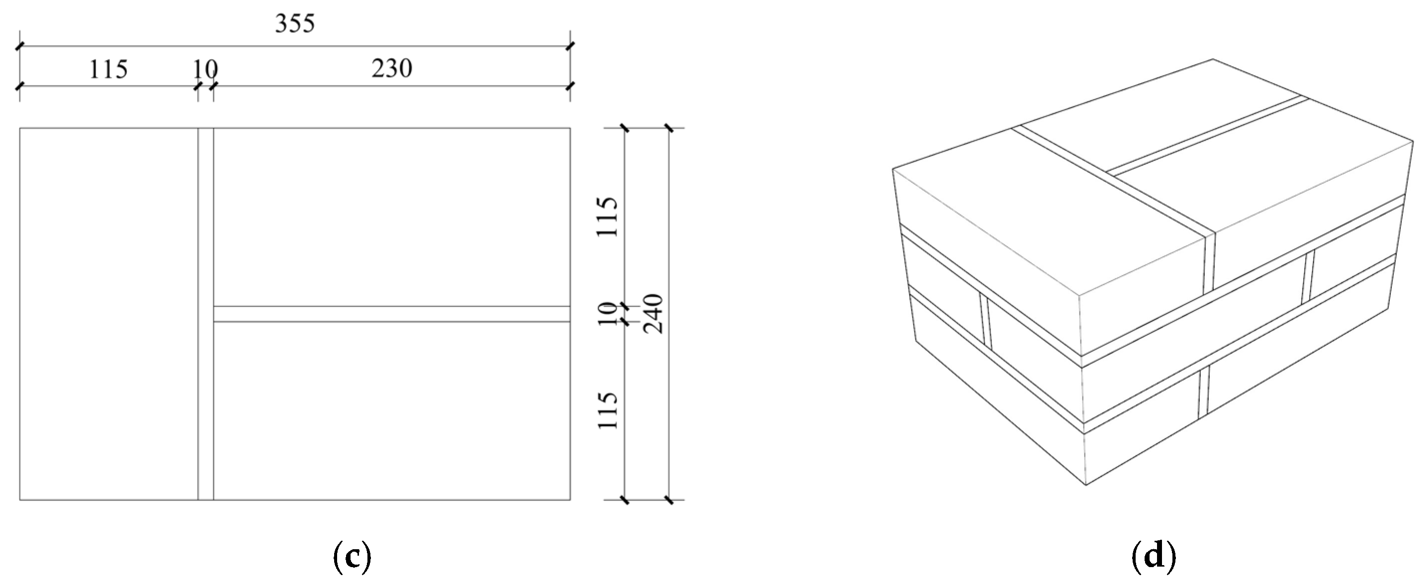
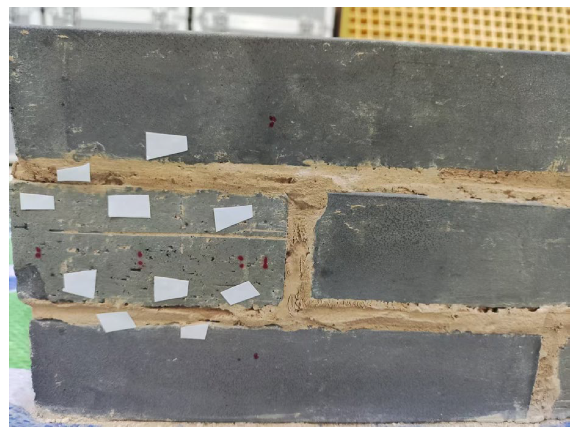
The specimens were constructed using fired clay grey bricks and glutinous rice mortar. Each grey brick had dimensions of 230 mm × 115 mm × 50 mm, and each masonry specimen consisted of nine bricks with a mortar joint thickness of 10 mm, as shown in
Figure 2. The assembled masonry specimens were cured under laboratory conditions for 28 days before surface preparation and CFRP bonding. CFRP sheets were bonded to the masonry surface using modified epoxy adhesive. The sheets were symmetrically arranged on both sides of the specimen to form a double-shear loading configuration. To prevent splitting failure of the masonry blocks during loading, U-shaped CFRP wrapping was applied at the sheet ends to ensure effective load transfer within the test region.
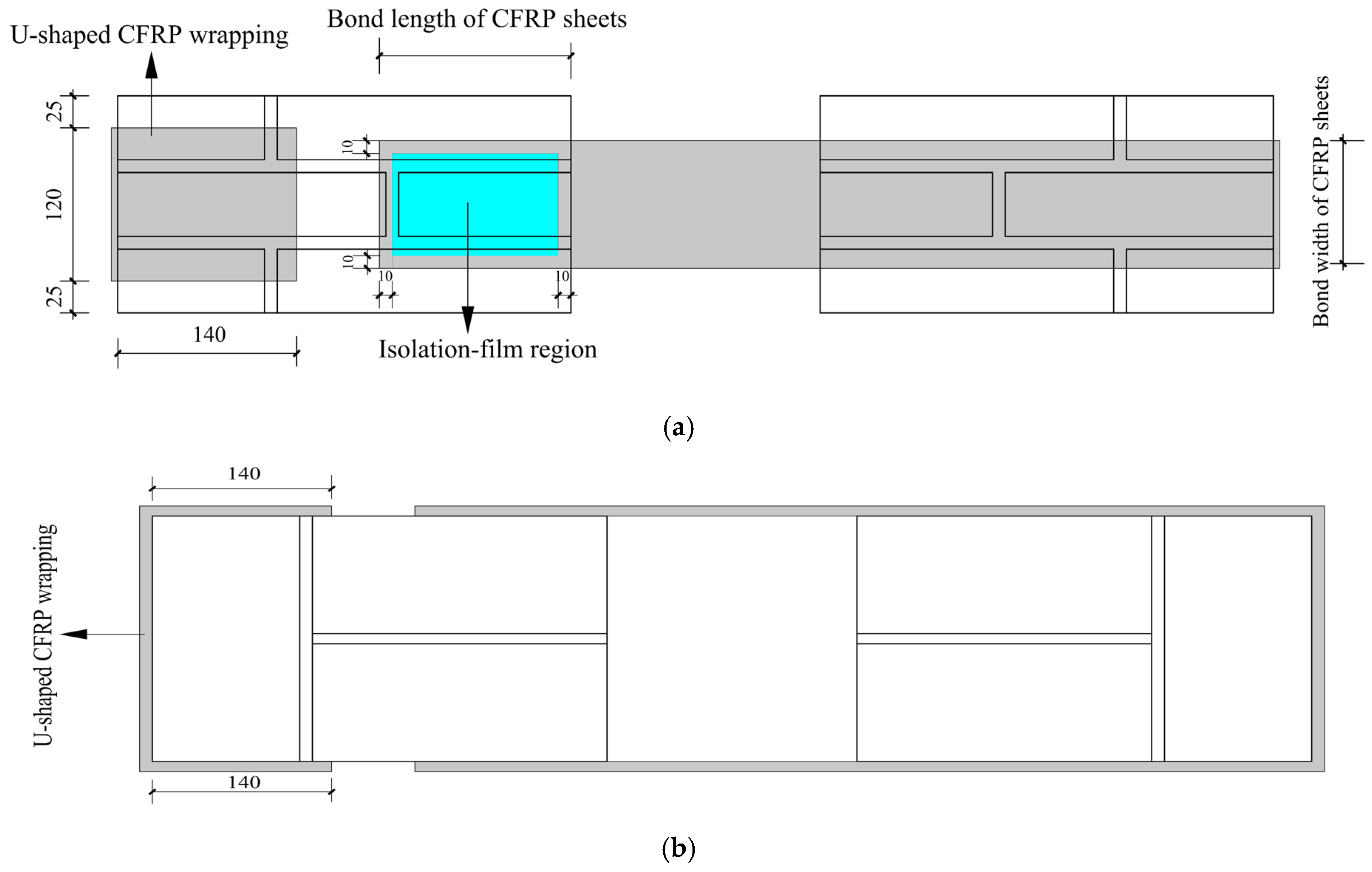
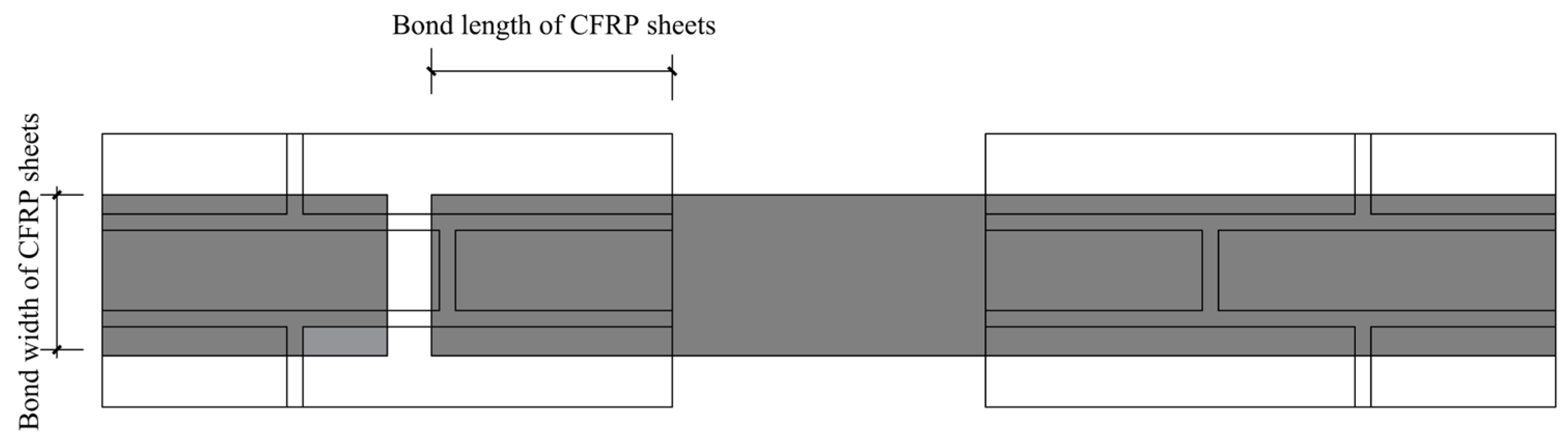
The detailed layout of the CFRP strengthening system, including the bond length, bond width, U-shaped CFRP wrapping, and isolation-film region, is shown in
Figure 3. The U-shaped CFRP wrapping was positioned at the sheet ends, with a wrapping length of 140 mm. The isolation films were arranged within the CFRP–masonry bonding region to generate artificial interface defects for specimens with predefined debonding ratios.
The details of the CFRP strengthening system were further specified to ensure the reproducibility of the tests. A single layer of CFRP sheet was used in all strengthened specimens, and the main mechanical properties of the CFRP sheet and modified epoxy adhesive are summarized in
Table 3.
Before CFRP bonding, the masonry surface was mechanically polished using an angle grinder to remove surface irregularities. Residual mortar was removed with a scraper, and surface dust was thoroughly cleaned using a clean towel. The CFRP sheets were cut along the principal fiber direction according to the designed bond dimensions.
A two-component modified epoxy adhesive was used for bonding. Component A, the resin matrix, and component B, the curing agent, were mixed at a volume ratio of A:B = 2:1 according to the manufacturer’s instructions. Because the bonding operation was conducted in winter, component A was indirectly heated in a water bath at 60–70 °C before mixing to reduce its viscosity and improve workability, while preventing water from entering the adhesive. The CFRP bonding operation was completed within the workable time of the adhesive.
During bonding, the modified epoxy adhesive was applied continuously and uniformly to the masonry surface. The CFRP sheets were then bonded and repeatedly rolled along the fiber direction using a dedicated roller to remove entrapped air, promote adhesive impregnation of the fiber bundles, and ensure a continuous bonded interface. After CFRP bonding, the strengthened specimens were cured under laboratory conditions for 7 days to ensure sufficient hardening of the adhesive before testing.
A total of 27 test cases were designed, considering three parameters: bond length (), bond width (), and debonding ratio (). The bond lengths were set as 100, 150, and 200 mm, while the bond widths were 50, 75, and 100 mm. The debonding ratios were selected as 0%, 10%, and 20%. Two identical specimens were prepared for each parameter combination. The average values of the repeated specimens were used for the comparison of peak-force-related parameters, while representative force–displacement curves were selected to illustrate the typical interfacial response.
The complete specimen matrix, including the individual peak force, peak displacement, observed failure mode, mean value, and coefficient of variation, is summarized in
Table 4.
The coefficients of variation in the repeated specimens were generally within a limited range, with several displacement-related values slightly exceeding 5%, which can be attributed to the inherent heterogeneity of traditional masonry materials and the sensitivity of interfacial slip measurements.
Considering that traditional brick masonry buildings may experience deterioration processes such as weathering and salt crystallization during long-term service, local unbonded regions may develop between CFRP sheets and masonry substrates. Therefore, different debonding ratios were introduced to simulate different levels of interface discontinuity. These cases were used to examine the influence of interface conditions on the interfacial bond behavior and to evaluate whether the bond-width-related performance variation was affected by local unbonded regions, rather than being treated as independent research variables.
The unbonded regions were controlled by placing isolation films at predetermined locations, resulting in specimens with
= 10% and 20%, as shown in
Figure 4. The debonding ratio was defined as the ratio of the unbonded area to the designed bonded area. The location of the isolation-film region relative to the loaded end is indicated by the blue region in
Figure 3a. The isolation films were arranged on the side CFRP–masonry bonding interface planes near the inner loaded ends, where interfacial shear transfer was expected to develop first during loading. Within the blue region, the isolation films were uniformly arranged to obtain a controlled and repeatable artificial defect distribution. This arrangement was adopted to represent a simplified condition of local interface discontinuities that may occur in practice, where defects may be spatially distributed rather than concentrated at a single point. Therefore, the debonding ratio should be interpreted together with the isolation-film arrangement shown in
Figure 3, since the adopted defect location and distribution can influence the interfacial stress-transfer process.
To characterize the strain response of the CFRP sheets during interfacial loading, strain gauges (Jincheng Testing Instrument Factory, Liyang, China) were installed along the fiber direction of the CFRP sheets on both sides of the masonry specimens. The measurement points were arranged along the bonded length, with distances of 10, 50, 90, 140, and 170 mm from the loaded end. The CFRP strain data were continuously recorded during the double-shear tests and were used to evaluate the interfacial load-transfer behavior.
3.2. Loading Procedure and Measurement Method
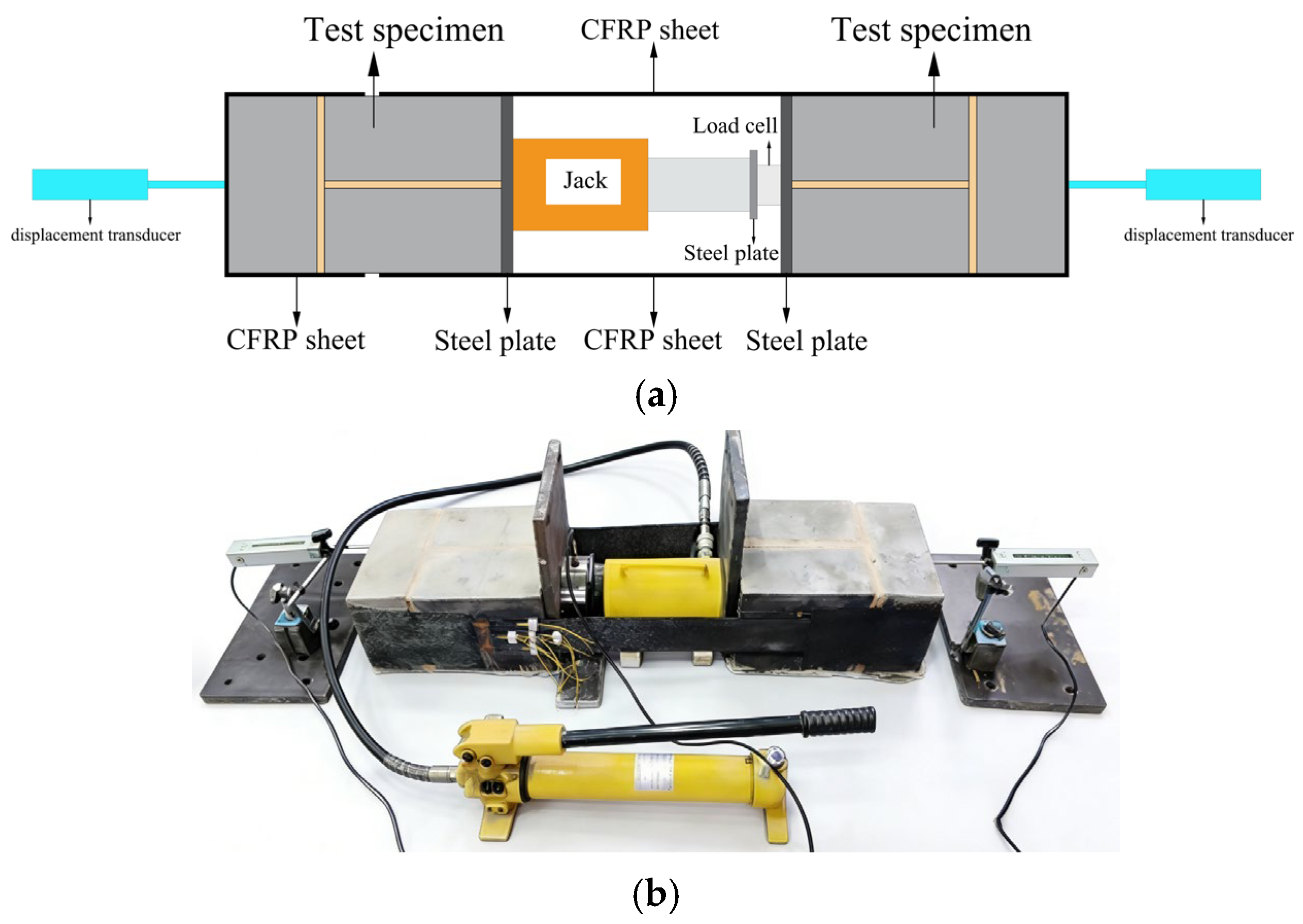
The loading setup for the double-shear test is shown in
Figure 5. During the test, a horizontal tensile force was applied to the central loading device, inducing synchronous tensile actions in the CFRP sheets bonded on both sides of the specimen. Consequently, shear transfer was generated along the CFRP–masonry interfaces. Displacement-controlled loading was adopted, and the applied force, displacement, and surface strain of the CFRP sheets were simultaneously recorded throughout the loading process. The CFRP sheets were symmetrically bonded on both sides of the masonry specimens. The bonded length and width were defined according to the dimensions of the CFRP sheets, as illustrated in
Figure 6.
In the double-shear configuration, two CFRP–masonry bonded interfaces were activated simultaneously. The force recorded by the load cell was the total actuator force applied to the specimen. Since the present study focused on the shear response of a single bonded interface, the force reported in the force–displacement curves and in
Table 4 was taken as one half of the total actuator force and is denoted as P.
The displacement reported in the force–displacement curves was measured by displacement transducers installed on both sides of the masonry specimen. During loading, the masonry specimen moved relative to the CFRP sheets; therefore, the measured displacement represents the relative displacement between the CFRP sheet and the masonry substrate, rather than the cross-head movement of the testing machine. This displacement includes the initial tightening deformation of the CFRP sheet and the subsequent interfacial slip between the CFRP sheet and the masonry substrate.
To characterize the interfacial stress transfer behavior, strain gauges were arranged along the bonded length of the CFRP sheets to obtain the strain distributions at different loading stages. Meanwhile, displacement measurement devices were installed on both sides of the specimens to record the relative deformation between the CFRP sheets and the masonry substrate during loading.
The force–displacement responses of the interfaces were obtained using the load acquisition and displacement measurement systems. Combined with the CFRP strain distributions, the interfacial bond behavior and load-transfer characteristics were evaluated.
3.3. Failure Modes and Observations
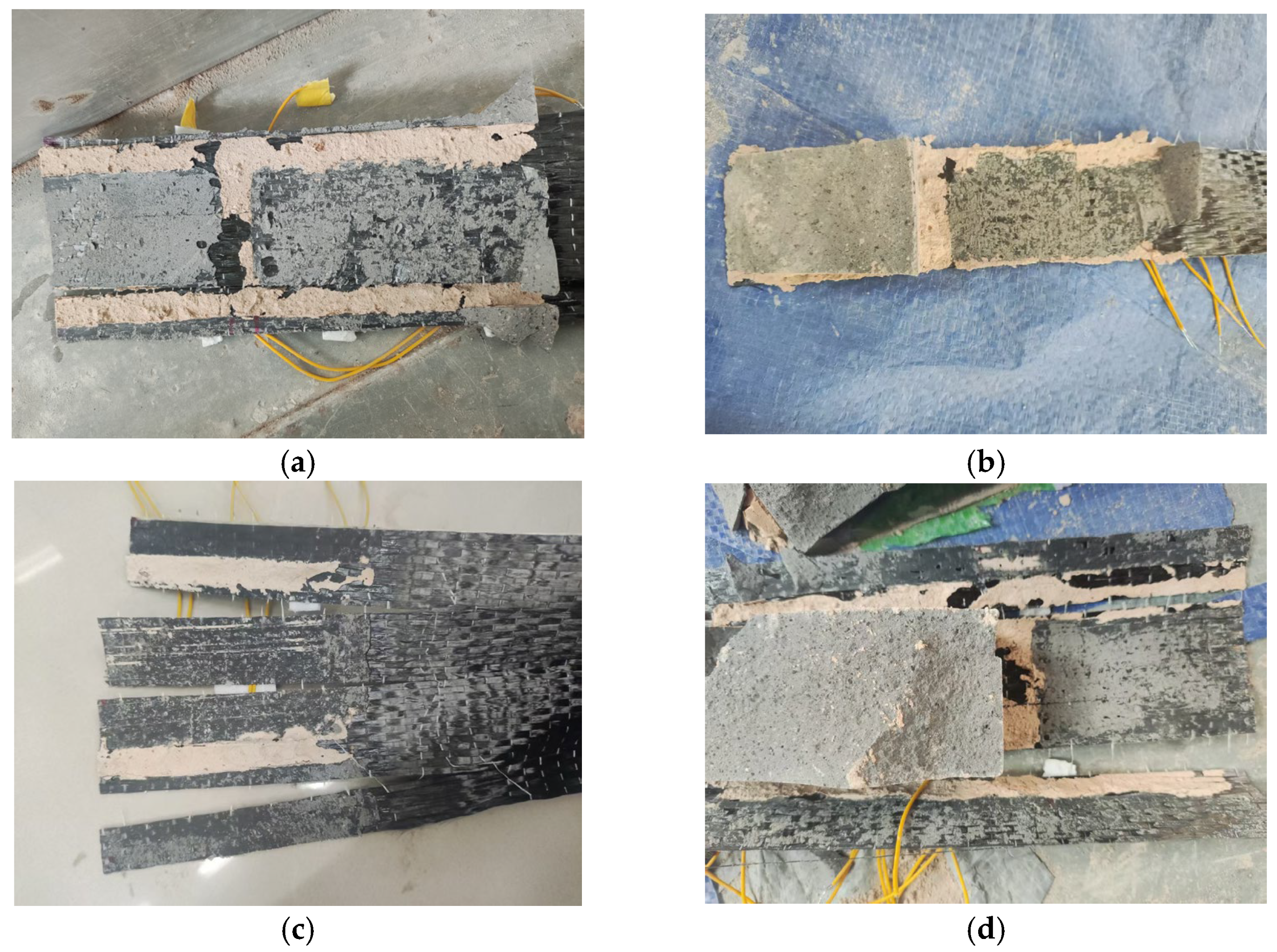
During the double-shear tests, the CFRP–glutinous rice mortar-bonded grey brick masonry interfaces exhibited different failure characteristics under increasing load. At the initial loading stage, the CFRP sheets and masonry substrate remained well bonded and deformed compatibly, resulting in an approximately linear increase in the force–displacement response. With further loading, local debonding initiated near the loaded end, accompanied by localized fiber rupture in some specimens. After reaching the peak force, interface separation and near-surface masonry damage developed, resulting in several typical failure modes, including interfacial debonding, coupled interfacial debonding and near-surface masonry damage, CFRP sheet rupture, and combined masonry damage and interfacial debonding, as shown in
Figure 7.
Figure 7a presents a typical interfacial debonding failure, where separation occurred between the CFRP sheet and masonry substrate, accompanied by detachment of part of the surface mortar.
Figure 7b shows a coupled failure mode involving CFRP debonding and near-surface masonry damage, where local separation of the CFRP sheet occurred together with shear cracking in the surface masonry layer.
Figure 7c corresponds to CFRP sheet rupture, where the CFRP fibers fractured along the loading direction while some bonded regions remained attached to the masonry surface.
Figure 7d illustrates the combined failure mode of masonry damage and interfacial debonding, where interface separation and masonry cracking occurred simultaneously during loading.
Overall, the observed failure modes were mainly characterized by interfacial debonding accompanied by local damage in the near-surface masonry layer. These results indicate that the load-carrying performance of CFRP-strengthened traditional masonry interfaces was primarily controlled by the interfacial bond behavior. Moreover, similar failure characteristics were observed under different bond widths, bond lengths, and debonding ratios, providing a basis for further evaluating the influence of bond width on interfacial load-carrying performance.
3.4. Interfacial Load-Carrying Behavior Under Different Bond Width Conditions
The nominal bond stress was calculated from the mean peak force of the two repeated specimens for each configuration and added to
Table 4 as a normalized index. As shown in
Table 4, the mean peak force generally increased with increasing bond width, whereas the nominal bond stress did not show a consistent increasing trend. For example, when L = 100 mm and ηd = 0%, increasing the bond width from 50 mm to 100 mm increased the mean peak force from 4.15 kN to 7.47 kN, while the nominal bond stress decreased from 0.83 MPa to 0.75 MPa. A similar trend was observed for specimens with L = 150 mm and ηd = 0%, where the nominal bond stress decreased from 0.83 MPa to 0.76 MPa.
These results indicate that the increase in peak force was mainly associated with the enlarged bonded area. Therefore, in this study, the bond width is interpreted primarily as a geometric parameter affecting the load-carrying capacity of the CFRP–masonry interface. Bond length and debonding ratio were introduced to provide different bonded-geometry and interface-integrity conditions for examining the consistency of the bond-width-related trend. In addition, increasing the debonding ratio generally reduced the nominal bond stress, indicating that artificial interface defects weakened the effective stress transfer across the interface.
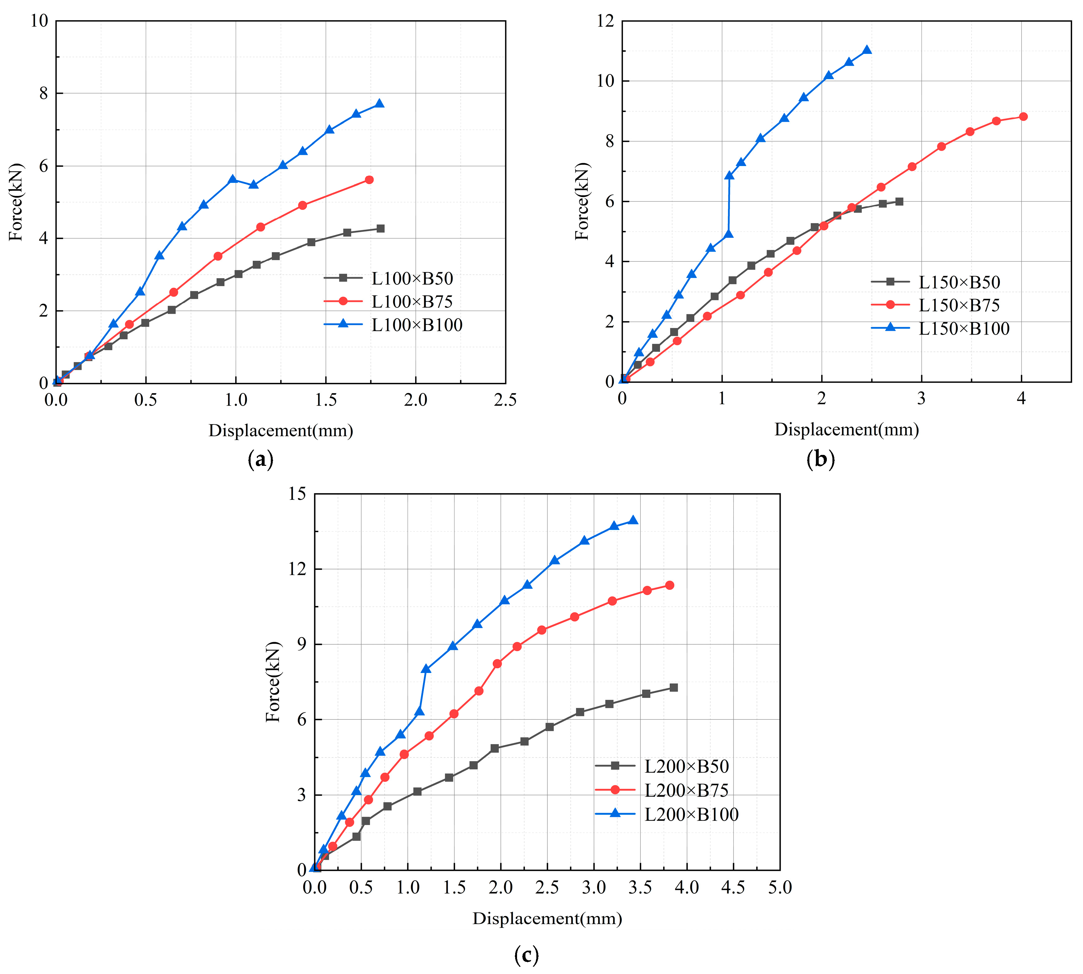
Figure 8,
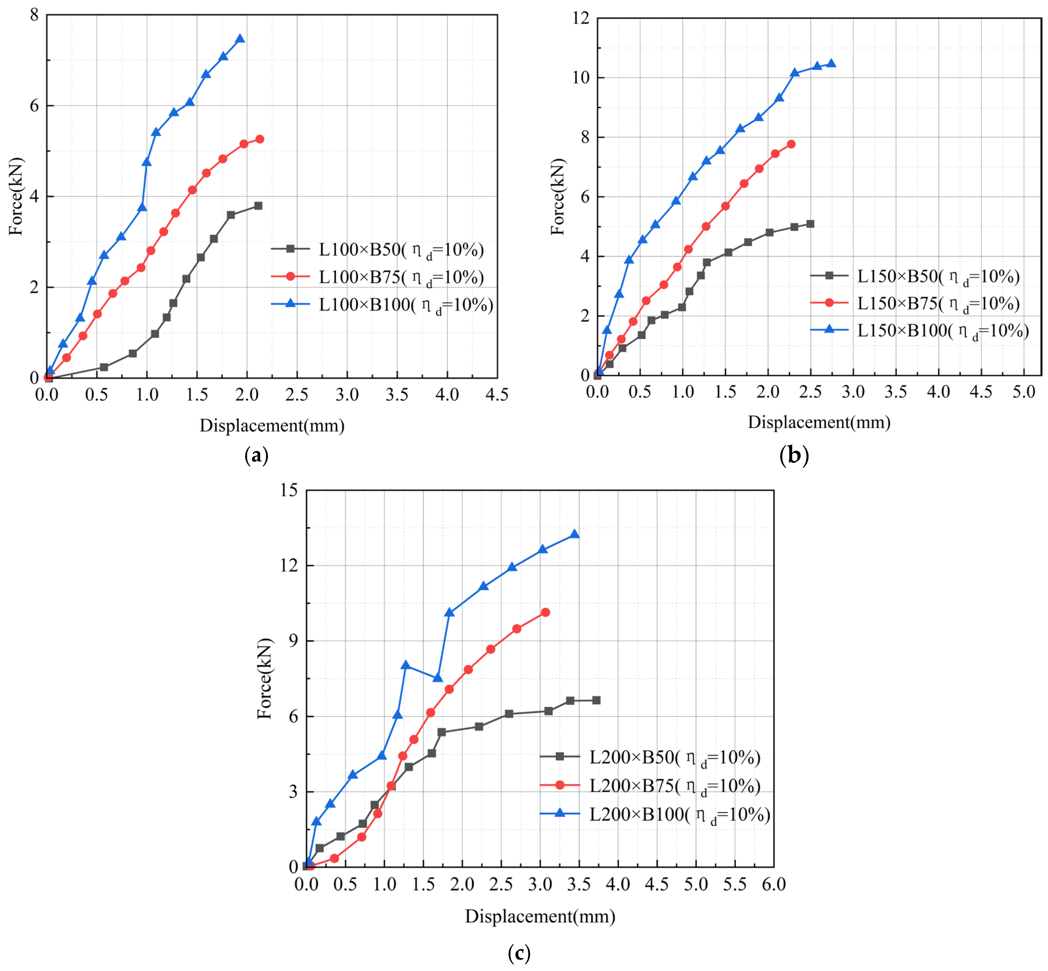
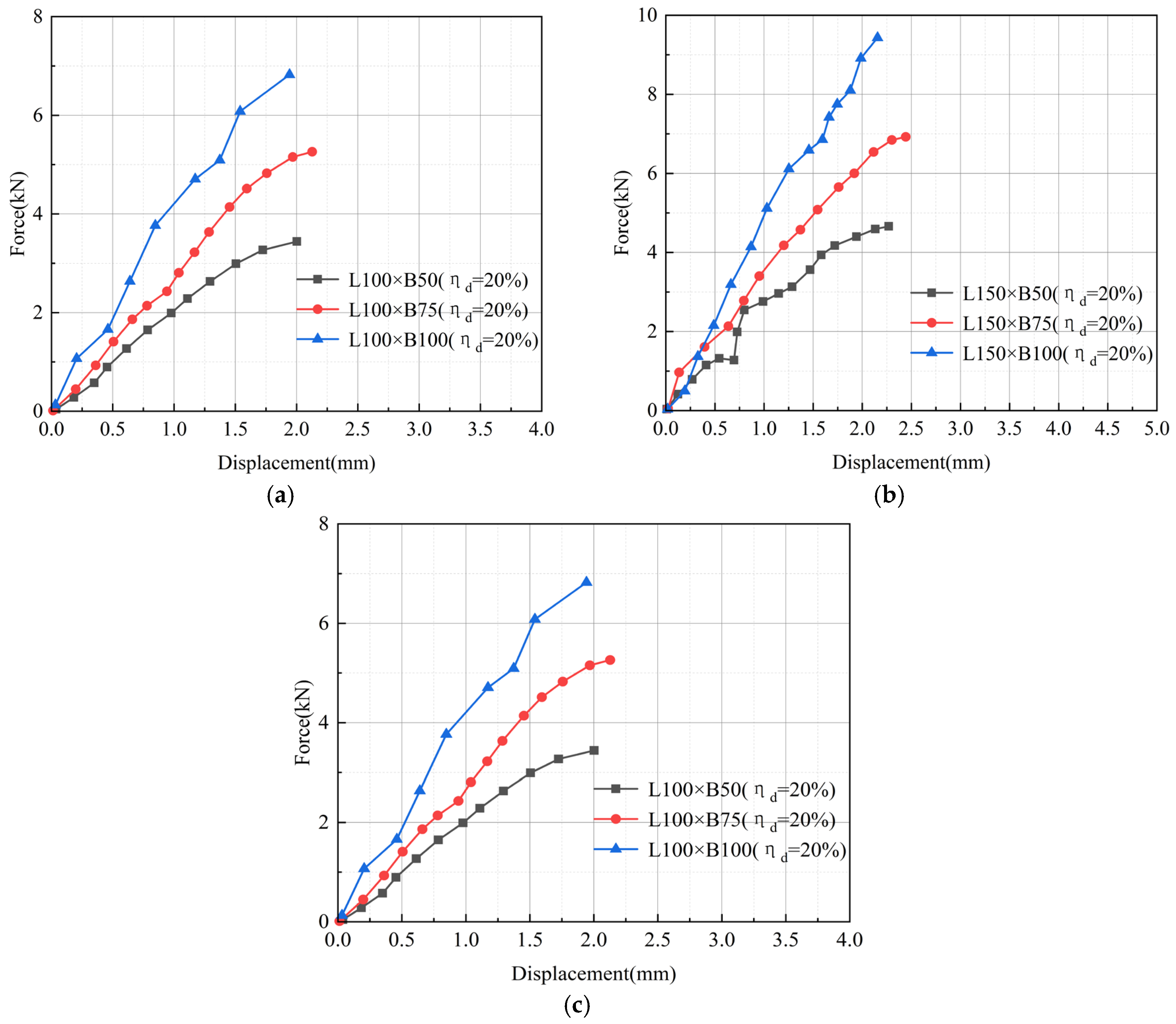
Figure 9 and
Figure 10 show representative force–displacement responses selected from the two repeated specimens for each configuration. The representative curve was selected from the specimen with a complete and stable testing record and a failure mode consistent with the main failure characteristics of that configuration. These curves were used to illustrate the typical interfacial response process under different bond widths, bond lengths, and interface integrity conditions. The experimental results demonstrate that increasing the CFRP bond width consistently improves the interfacial load-carrying capacity, and similar variation trends were observed under different bond lengths and interface integrity conditions. Although bond length and debonding ratio also affect the absolute load-carrying capacity of the interface, they were mainly considered herein to provide different bonding conditions for examining the observed bond-width-related response.
Taking the specimens with a bond length of L = 100 mm as an example, when the bond width increased from 50 mm to 100 mm, the peak shear forces per bonded interface of specimens with intact interfaces, 10% debonding ratio, and 20% debonding ratio increased by 80.3%, 96.1%, and 98.4%, respectively. Similar enhancement trends were observed for specimens with bond lengths of 150 mm and 200 mm, with capacity increases ranging from 83.6% to 114.8%. These results indicate that increasing the bond width effectively improves the interfacial load-carrying capacity and that the width-related trend remains consistent within the investigated parameter range.
Further analysis of the force–displacement curves show that increasing the bond width shifts the curves upward and increases the initial slope, indicating an increase in the initial interfacial stiffness. Under the same displacement level, specimens with larger bond widths sustained higher forces, demonstrating improved load-transfer efficiency due to the enlarged effective bonded area. Although debonding regions reduced the overall force level and introduced local fluctuations, the capacity ranking among different bond widths remained unchanged, indicating that bond width has an important influence in the interfacial load-carrying behavior within the investigated range.
3.5. CFRP Strain Response During Interfacial Loading
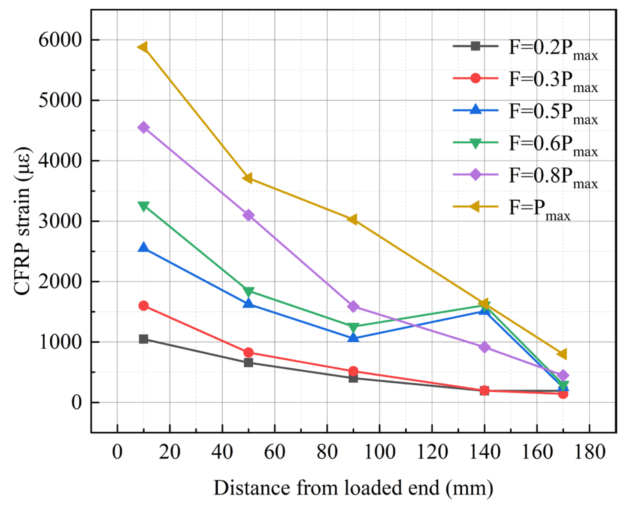
To further investigate the mechanical response of the CFRP–glutinous rice mortar masonry interface, strain gauges were installed along the fiber direction of the CFRP sheet to monitor the deformation response during loading. Considering that the specimen with a larger bonded area exhibited more complete load-transfer characteristics, a representative specimen with a bond length of 200 mm and a bond width of 100 mm under an intact interface condition (L200 × B100, ηd = 0%) was selected for analysis.
Figure 11 presents the CFRP strain distributions at different loading levels, corresponding to 20%, 30%, 50%, 60%, 80%, and 100% of the peak interfacial capacity.
As shown in
Figure 11, the CFRP strain exhibited a gradual decrease from the loaded end toward the free end throughout the loading process. During the initial loading stage, the CFRP sheet and masonry substrate maintained compatible deformation, and the strain level within the bonded region increased progressively with increasing load while the overall distribution pattern remained stable. With further loading, the CFRP strain near the loaded end continued to increase, whereas the strain growth in regions farther from the loaded end was relatively limited. This indicates that the interfacial shear transfer gradually developed from the loaded end toward the bonded region, forming a continuous load-transfer process between the CFRP sheet and masonry substrate.
When the applied load approached the peak interfacial capacity, obvious strain concentration occurred near the loaded end, where the strain growth rate became higher than that in other regions. This phenomenon was consistent with the interfacial debonding and near-surface masonry damage observed during the tests, indicating that the local interface region experienced relatively higher shear transfer demand near the peak load stage.
Based on the measured CFRP strain profiles, the average local interfacial shear stress between adjacent strain gauges was further estimated from the strain gradient. For two adjacent strain gauges located at
and
, the average local interfacial shear stress can be expressed as
where
and
are the elastic modulus and nominal thickness of the CFRP sheet, respectively;
and
are the CFRP strains measured at two adjacent positions. The strain values were converted from microstrain to dimensionless strain before calculation. Therefore, the calculated
represents the average interfacial shear stress over the interval between two adjacent strain gauges.
As shown in
Table 5, the estimated average local interfacial shear stress generally increased with the applied load level. At the peak load, the highest value was obtained in the 10–50 mm interval, indicating that the region close to the loaded end carried a relatively high shear-transfer demand. This is consistent with the CFRP strain distribution shown in
Figure 11, where higher strain and a larger strain gradient were observed near the loaded end.
The strain profiles also indicate that the main load-transfer region was concentrated near the loaded end at the early loading stage and gradually extended toward the free end as the applied load increased. Since the identification of a numerical transfer length is sensitive to the selected threshold criterion, the present analysis focuses on the qualitative evolution of the load-transfer region rather than a fixed transfer-length value. In addition, local fluctuations were observed in some intervals, indicating that the strain-gradient-based shear stress values should be interpreted as interval-averaged estimates rather than continuous local shear-stress distributions.
Additional strain profiles from specimens with different bond widths and repeated tests were also examined. These profiles showed similar overall characteristics, namely that the CFRP strain was relatively higher near the loaded end and gradually decreased toward the free end. Therefore, only the representative L200 × B100 specimen is presented in
Figure 11 to illustrate the typical strain-development and load-transfer process, while avoiding excessive repetition of similar strain-profile results. The strain comparison is used as supporting evidence for the representative load-transfer pattern rather than as a complete quantitative comparison among all bond-width conditions.
4. Numerical Simulation and Parametric Analysis
4.1. Finite Element Model Development
The double-shear test results demonstrated that the failure of most specimens was dominated by interfacial debonding between the CFRP sheet and masonry substrate, sometimes accompanied by local damage in the near-surface masonry layer. Therefore, the finite element analysis focused on reproducing the interfacial bond behavior and load-transfer characteristics of the CFRP–masonry interface.
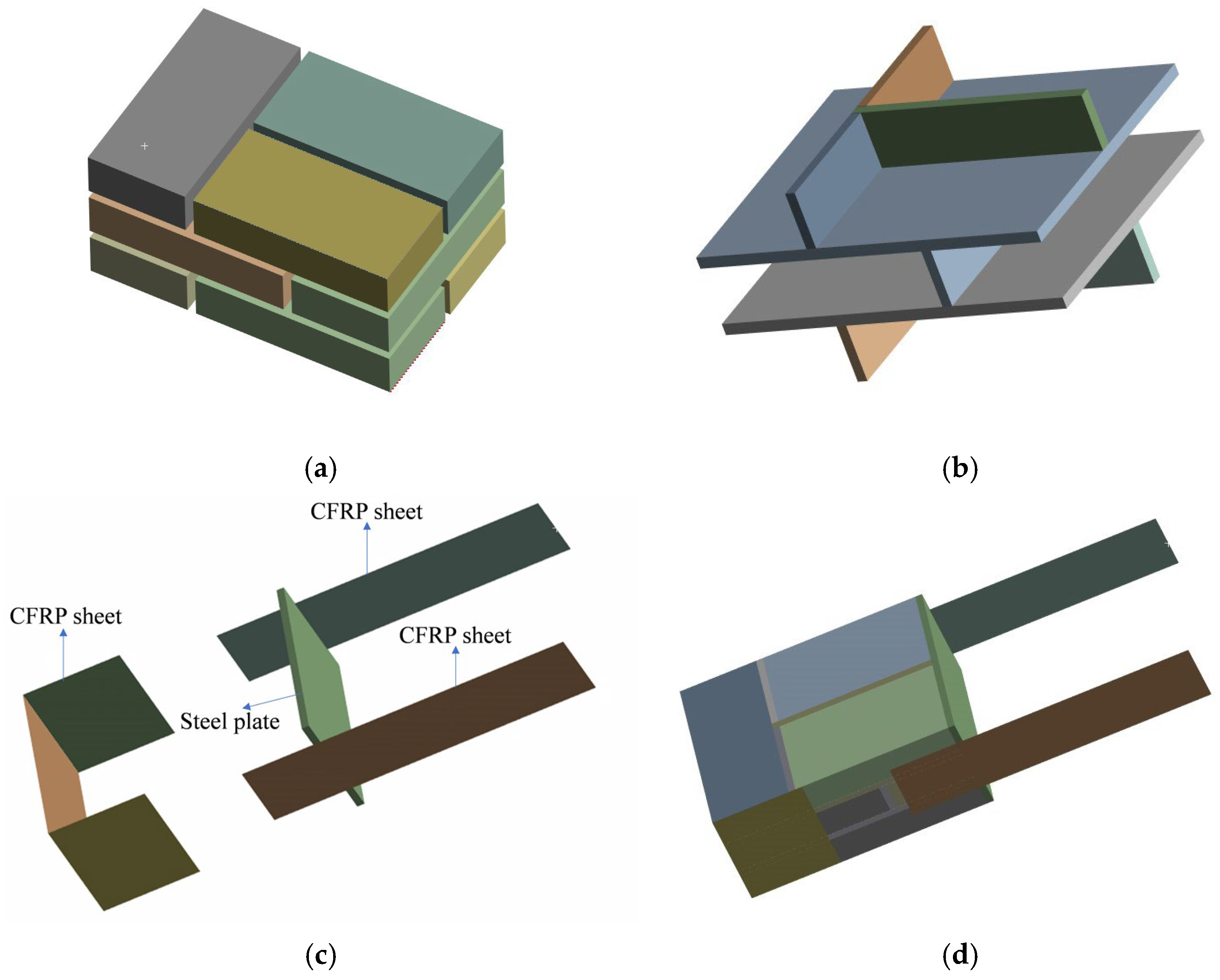
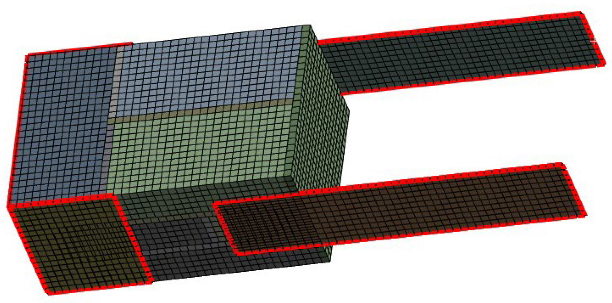
A finite element model consistent with the double-shear test configuration was developed to further investigate the interfacial behavior between CFRP sheets and glutinous rice mortar-bonded grey brick masonry. A separated modeling approach was adopted, in which the fired clay grey bricks, glutinous rice mortar, CFRP sheets, and loading steel plates were modeled individually, as shown in
Figure 12 and
Figure 13. The dimensions of the grey bricks were 230 mm × 115 mm × 50 mm, the mortar joint thickness was 10 mm, and the CFRP sheet thickness was 0.111 mm. Solid elements were used to simulate the grey bricks and glutinous rice mortar, while shell elements were adopted for the CFRP sheets. The interface between the CFRP sheet and masonry substrate was simulated using zero-thickness interface elements to represent the interfacial bonding behavior and debonding process. A swept meshing method was used, and a typical element size of approximately 10 mm was adopted in the bonded region and adjacent masonry substrate. An independent mesh-sensitivity analysis was not conducted in the present study. The adopted mesh size was selected to provide a refined discretization in the bonded region and adjacent masonry substrate, and the adequacy of the mesh was evaluated through the comparison between the numerical and experimental force–displacement responses in
Section 4.2.
Accurate simulation of interfacial bonding and debonding behavior is essential for reproducing the mechanical response of CFRP-strengthened masonry interfaces. In this study, an interface formulation available in the finite element software ANSYS 19.0 (ANSYS Inc., Canonsburg, PA, USA) was adopted to describe the traction–separation relationship between the CFRP sheet and masonry substrate, enabling simulation of interfacial bonding and debonding behavior under loading [
36,
37,
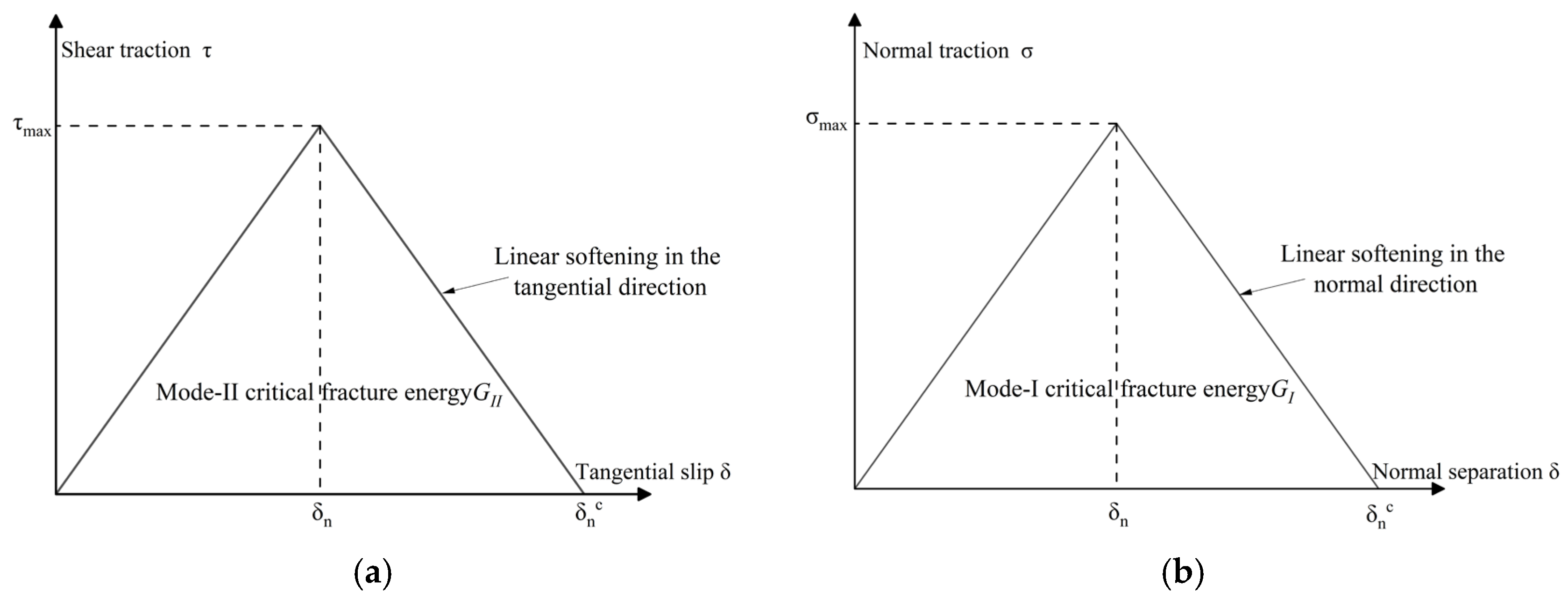
38]. A bilinear traction–separation relationship was employed, as shown in
Figure 14. The main parameters included the maximum normal contact stress, maximum equivalent tangential contact stress, normal fracture energy, tangential fracture energy, and artificial damping coefficient. The cohesive parameters were treated as calibrated interface parameters rather than directly measured local bond–slip properties.
The interface parameters were determined based on the results of the reference experimental specimens. The maximum equivalent tangential contact stress was calculated according to the peak force:
where
is the peak shear force transferred by one bonded interface (kN), obtained as one half of the peak total actuator force recorded by the load cell;
is the effective bonded area of one CFRP–masonry interface (mm
2); and
is the maximum equivalent tangential contact stress (MPa). In the calculation,
was converted from kN to N.
The value calculated using Equation (3) represents an average bonded-area stress. Therefore, it was used as an equivalent tangential cohesive strength in the simplified cohesive-zone model. This equivalent treatment was adopted to reproduce the global force–displacement response and the overall interfacial stress-transfer characteristics, rather than to determine a local bond–slip law.
The equivalent cohesive parameters were determined from the experimental response of the representative L100 × B50 specimen used for numerical calibration, where L and B denote the bond length and bond width, respectively, and were then kept unchanged in the subsequent numerical simulations. The maximum equivalent tangential contact stress was calculated using Equation (3), while the tangential fracture energy was determined from the force–displacement response during the complete interfacial debonding stage. Considering that the double-shear tests were mainly governed by shear transfer, the normal interface parameters were determined according to the ratio between shear and tensile interface properties reported in previous FRP interface studies [
39]. The adopted interface parameters are summarized in
Table 6.
The material parameters used in the numerical model were taken from the experimental measurements reported in the preceding sections. The fired clay grey bricks and glutinous rice mortar were described using ideal elastoplastic constitutive models, while the CFRP sheets were assumed to behave linearly elastically before interface failure. The fired clay grey bricks and glutinous rice mortar joints were modelled as separate solid components according to the specimen geometry. No separate cohesive law was assigned to the brick–mortar joints; the cohesive-zone model was used for the CFRP–masonry bonding interface.
The boundary conditions were simplified based on the experimental loading method. The edges of the CFRP sheets were fixed, and displacement-controlled loading was applied to the surface of the steel plate. The displacement increment was 0.2 mm for each loading step, and a total of 40 loading steps were used, corresponding to a total imposed displacement of 8 mm.
For the specimens with artificial interface defects, the deboned regions were simulated by partitioning the CFRP shell elements according to the designed defect area. The CFRP shell elements in the deboned regions were retained, whereas the contact relationship between these CFRP shell elements and the masonry substrate was suppressed. Therefore, the deboned regions were represented as initial unbonded interface defects without contact or cohesive stress transfer.
It should be noted that the present finite element model was developed mainly to reproduce the global force–displacement response, CFRP strain distribution, and dominant CFRP–masonry interfacial debonding behaviour. The near-surface masonry damage observed in some tests was not explicitly simulated as discrete cracking or fracture propagation of the brick or mortar substrate. Instead, the influence of local substrate damage was reflected in an equivalent manner through the degradation and failure of the cohesive interface. Therefore, the numerical results should be interpreted as simulations of the dominant interfacial debonding response and stress-transfer characteristics, rather than as a detailed fracture analysis of the masonry substrate.
4.2. Experimental–Numerical Comparison
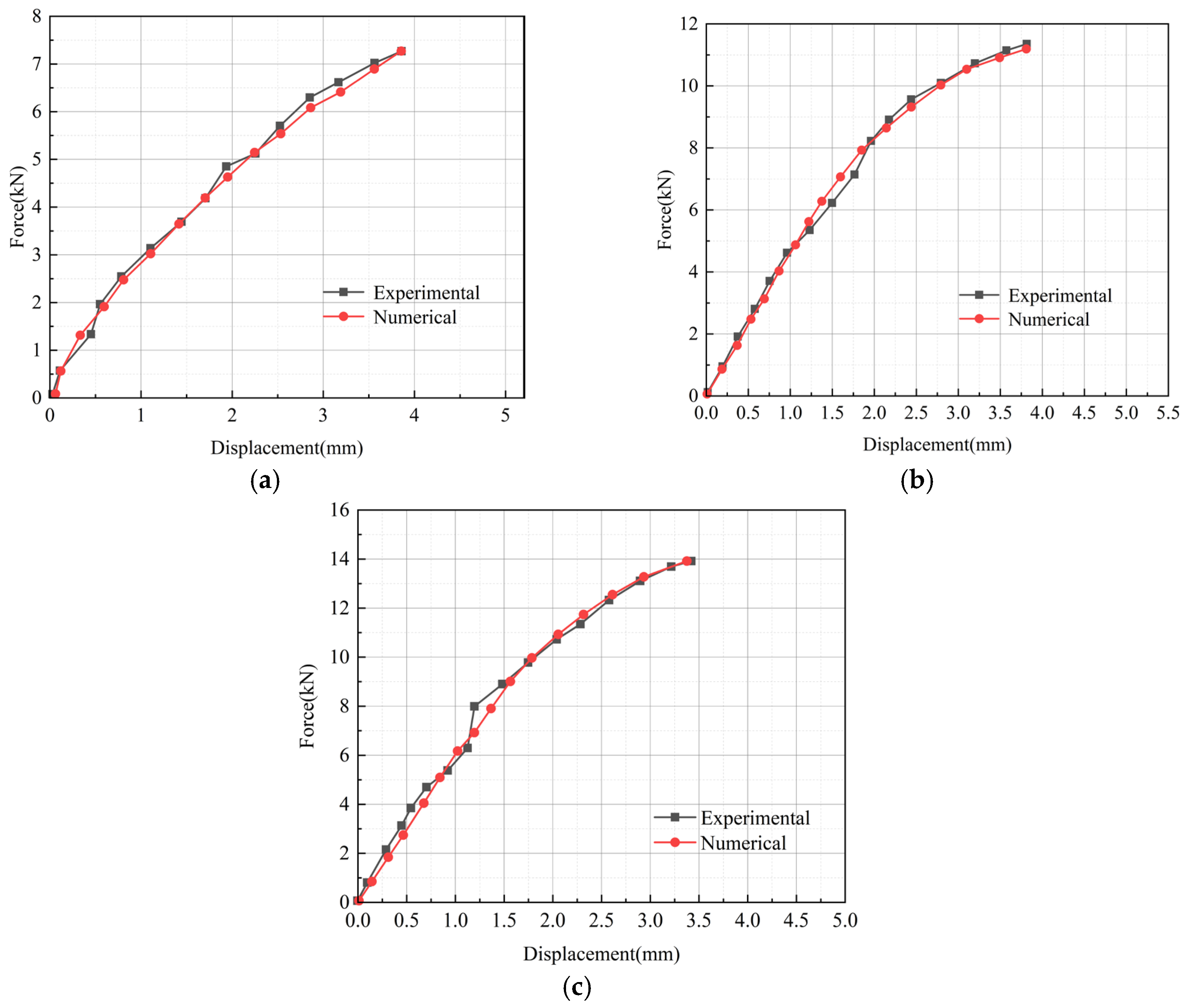
To examine the ability of the developed finite element model to reproduce the main experimental response, the L200 × B50, L200 × B75, and L200 × B100 specimens were selected for experimental–numerical comparison, as shown in
Figure 15. These three specimens were not used for determining the cohesive parameters. As described in
Section 4.1, the equivalent cohesive parameters were determined from the experimental response of the L100 × B50 specimen and were then kept unchanged in the subsequent numerical simulations. Therefore, the comparison with the L200 specimens was used to evaluate the model’s ability to reproduce the global force–displacement response and overall load-transfer characteristics after the interface parameters had been fixed.
As shown in
Figure 15, the numerical results reproduced the overall variation trends of the experimental curves, including the initial linear stage, peak load stage, and post-peak stiffness degradation stage. Under different bond width conditions, the numerical and experimental curves showed good consistency, indicating that the developed finite element model can reasonably describe the load-transfer behavior of the CFRP–masonry interface.
To further quantify the agreement between the experimental and numerical results, the peak force, peak displacement, and initial stiffness of the representative L200 specimens were compared, as summarized in
Table 7. The comparison shows that the numerical model reproduced the peak force and peak displacement of the selected specimens with relatively small errors, while the initial stiffness was also captured with reasonable consistency. The slightly larger stiffness errors may be attributed to the simplified equivalent interface model and the inherent heterogeneity of the traditional masonry substrate. These results provide quantitative support for the experimental–numerical comparison shown in
Figure 15.
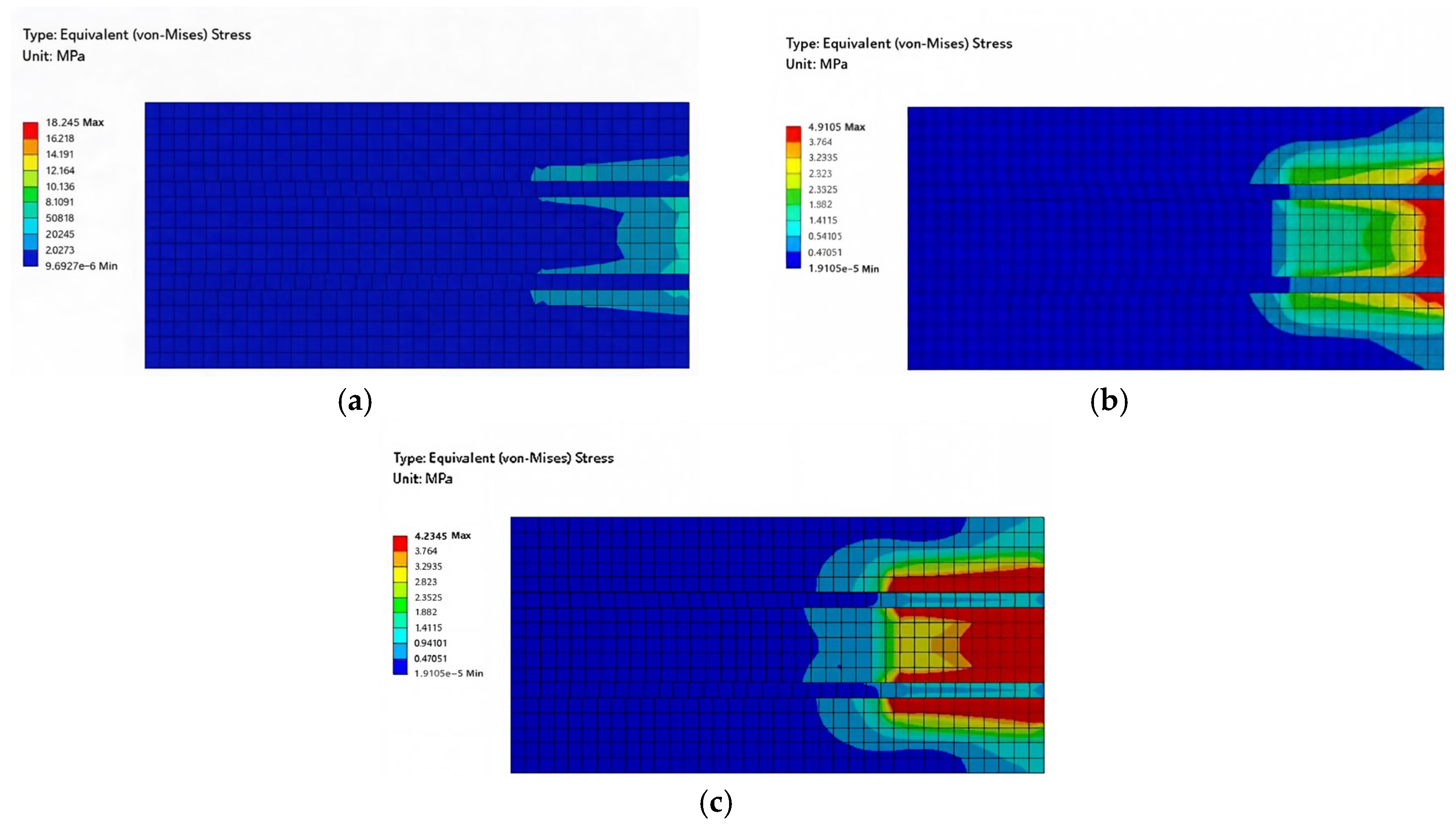
The numerical results further indicated that stress concentration mainly occurred near the loaded end and gradually extended along the bonded region with increasing displacement, which was consistent with the interfacial debonding and near-surface masonry damage observed in the double-shear tests. This agreement demonstrates that the numerical model can effectively capture the interfacial stress transfer characteristics and overall mechanical response of CFRP-strengthened traditional masonry interfaces. After this experimental–numerical comparison, the finite element model was further employed for parametric analysis of bond width effects.
4.3. Numerical Investigation of Load-Transfer Characteristics Under Different Bond Width Conditions
The experimental results demonstrated that the influence trend of bond width on the interfacial load-carrying performance remained consistent under different interface conditions. Therefore, the verified finite element model was further employed to extend the bond width range and evaluate the influence of bond width on interfacial capacity, stiffness variation, and load-transfer characteristics.
Based on the verified model, a parametric analysis was conducted to further evaluate the role of bond width. To examine the influence of bond width under a consistent bonding condition, all extended numerical cases were established with a constant bond length of L = 200 mm and an intact interface condition. In addition to the experimentally investigated bond widths of B = 50, 75, and 100 mm, four additional cases with bond widths of B = 62.5, 87.5, 112.5, and 125 mm were considered. The detailed parameters of the extended cases are summarized in
Table 8.
Figure 16 presents the stress distribution at different loading stages, which is used to characterize the load-transfer process and interfacial response of the CFRP–masonry interface. According to the numerical results, the loading process of the CFRP–masonry interface can be divided into three stages: the elastic stage, nonlinear load-transfer stage, and interfacial debonding stage.
During the elastic stage, the CFRP sheet and masonry substrate maintained compatible deformation, and the force–displacement response exhibited an approximately linear trend. The stress distribution within the bonded region was relatively uniform during the initial loading stage. With increasing displacement, nonlinear interfacial response gradually developed near the loaded end, accompanied by local stress redistribution and interfacial slip, resulting in a reduction in the slope of the force–displacement curve. As the peak force was approached, the stress concentration region gradually extended along the bonded length, and interfacial separation occurred, eventually leading to complete debonding. This stress-transfer process was consistent with the debonding behavior observed in the double-shear tests.
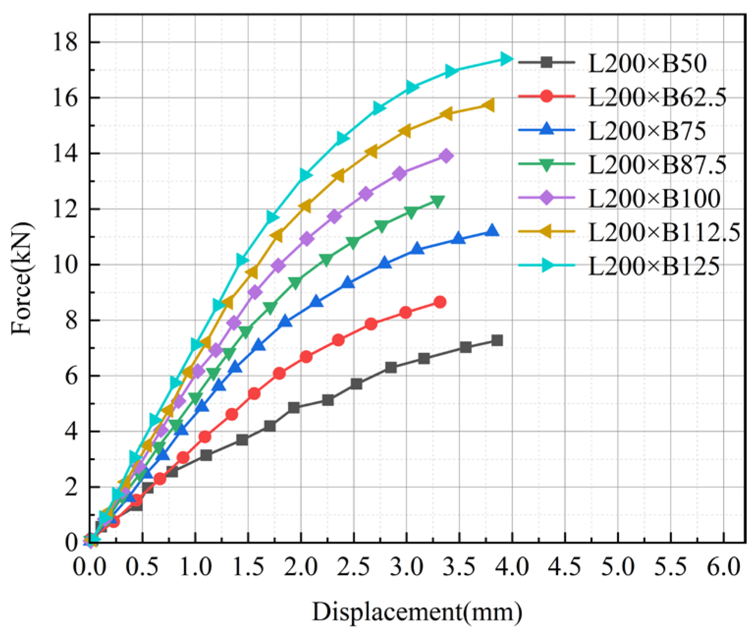
Figure 17 shows the force–displacement responses of the interface with different bond widths. Overall, all cases exhibited similar nonlinear response characteristics, while the curves shifted upward with increasing bond width. Bond width exhibited a significant influence on the ultimate interfacial capacity. For a constant bond length of L = 200 mm, increasing the bond width from 50 mm to 125 mm increased the ultimate capacity from 7.27 kN to 17.40 kN, corresponding to an increase of approximately 139%. The ultimate capacities for bond widths of 62.5, 75, 87.5, 100, 112.5, and 125 mm were approximately 8.65, 11.19, 12.32, 13.92, 15.74, and 17.40 kN, respectively. These results indicate that, within the investigated range, the ultimate interfacial capacity increased approximately linearly with increasing bond width. It should be noted that this nearly linear increase is partly associated with the increase in bonded area under the adopted equivalent cohesive-zone model. Therefore, the width-related increase in numerical capacity should not be interpreted as an independent enhancement of the local interfacial bond property.
From a mechanical perspective, increasing the bond width enlarges the effective load-transfer region between the CFRP sheet and masonry substrate, allowing wider CFRP sheets to participate in load transfer over a larger bonded area. However, this effect should be interpreted as a geometry-related stress-transfer mechanism within the adopted model and tested parameter range, rather than as a direct improvement in the intrinsic local bond strength of the CFRP–masonry interface.
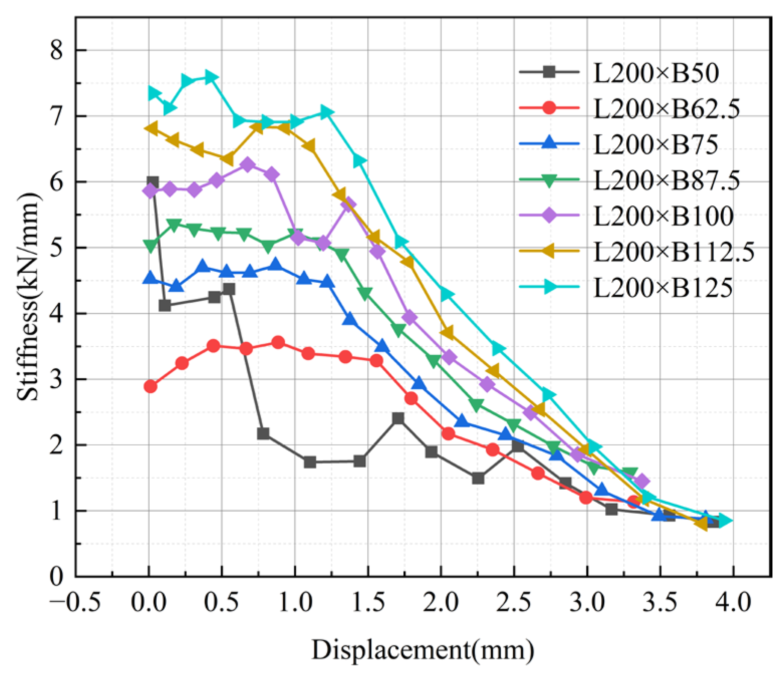
Figure 18 presents the evolution of interfacial stiffness with displacement for different bond widths. The stiffness curves were obtained by calculating the first derivative of the force–displacement relationship and were used to characterize the variation in interfacial stiffness during loading. During the initial loading stage, all cases exhibited relatively high stiffness, and specimens with larger bond widths showed higher initial stiffness, indicating improved early-stage load-transfer capability. With increasing displacement, nonlinear interfacial response gradually developed near the loaded end, resulting in a continuous decrease in interface stiffness and increasing differences among specimens with different bond widths. Compared with narrower CFRP sheets, specimens with larger bond widths maintained higher stiffness over a wider displacement range, demonstrating that increasing bond width contributes to maintaining interfacial stiffness during loading.
At the final stage, the stiffness of all cases gradually decreased to a relatively low level, indicating that the contribution of interfacial bonding to load transfer was reduced under large deformation conditions. At this stage, the influence of bond width on stiffness became less significant.
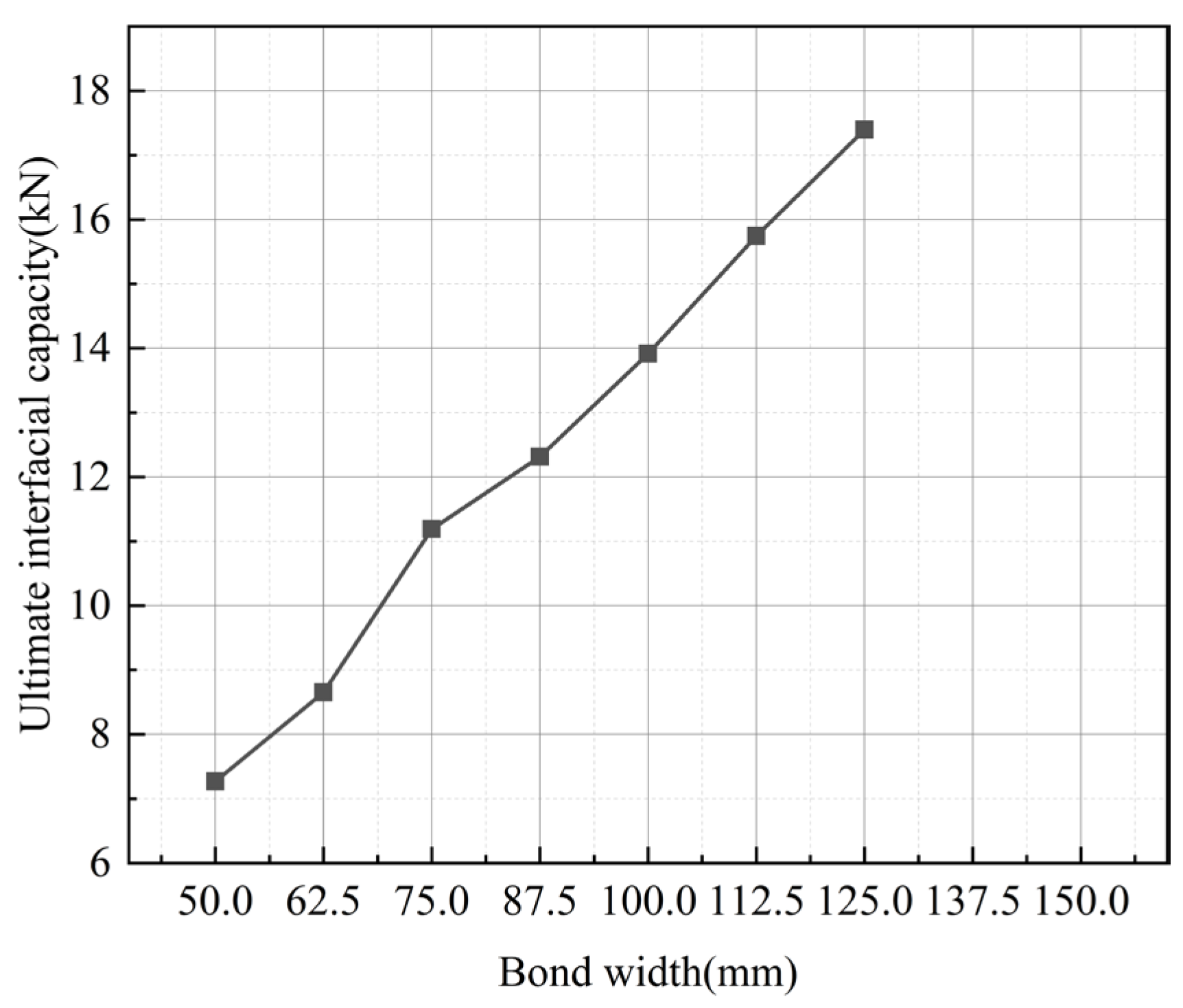
Figure 19 further illustrates the relationship between ultimate interfacial capacity and bond width. As shown in the figure, the ultimate capacity increased monotonically with increasing bond width, with a relatively stable growth rate. When the bond width increased from 50 mm to 125 mm, the ultimate capacity increased from approximately 7.27 kN to 17.40 kN, corresponding to an increase of approximately 139%. This result indicates that bond width is an important geometric parameter affecting the load-carrying performance of CFRP–masonry interfaces within the investigated range.
To avoid evaluating the width effect only based on the absolute peak force, the nominal bond stress listed in
Table 4 was used as a normalized index. The nominal bond stress was calculated as the peak shear force transferred by one CFRP–masonry bonded interface divided by the effective bonded area of one interface. The results show that the increase in absolute peak force with bond width does not necessarily correspond to a proportional increase in nominal bond stress. This indicates that the observed increase in capacity is mainly related to the enlarged bonded area and the corresponding extension of the stress-transfer region.
Overall, increasing the bond width enhanced the ultimate interfacial capacity and contributed to maintaining interfacial stiffness during loading within the investigated range. However, the present numerical analysis mainly focused on the influence of bond width under a constant bond length of L = 200 mm. The effective bond length was not independently determined in this study. Therefore, the width-related trend should be interpreted within the tested bond-length and bond-width ranges, rather than as a general effective-bond-length rule for CFRP-strengthened masonry interfaces. In addition, existing FRP-to-masonry bond-strength formulations have mostly been developed or calibrated using conventional masonry substrates and adhesive systems. Since the present study focuses on traditional grey brick masonry bonded with glutinous rice mortar, direct application of these formulations may introduce uncertainty. Therefore, the present results are used mainly to interpret the tested material system and geometries, while systematic comparison with existing design formulations should be further examined using expanded experimental datasets.