Article

Seismic Response Mitigation of Reinforced-Concrete High-Speed Railway Bridges with Hierarchical Curved Steel Dampers

1
School of Civil Engineering, Central South University, Changsha 410075, China
2
National Engineering Research Center for High-Speed Railway Construction, Changsha 410075, China
*
Author to whom correspondence should be addressed.
Materials 2025, 18(9), 2120; https://doi.org/10.3390/ma18092120
Submission received: 21 March 2025 / Revised: 20 April 2025 / Accepted: 28 April 2025 / Published: 5 May 2025

Abstract

:
To address the seismic vulnerability of high-speed railway bridges (HSRBs) in seismically active regions, this study proposes a hierarchical curved steel damper (CSD) designed to mitigate excessive girder displacements induced by conventional isolation devices. The CSD integrates U-shaped and hollow diamond-shaped steel plates to achieve stable energy dissipation through coupled bending deformation. A finite element model is developed, and its hysteretic behavior is confirmed, with an energy dissipation coefficient of 1.82 and an equivalent damping ratio of 12.7%. An integrated high-speed railway track–bridge-CSD spatial coupling model is developed in OpenSees, which incorporates nonlinear springs for interlayer track interactions. Nonlinear time–history analyses under 40 spectrum-matched ground motions reveal that the CSD reduces transverse girder displacements by 73.7–79.2% and attenuates track slab acceleration peaks by 52.4% compared with uncontrolled cases. However, it increases the maximum bending moment at pier bases by up to 18.3%, necessitating supplemental energy-dissipating components for balanced force redistribution. This work provides a theoretical foundation and practical methodology for seismic response control and retrofitting of the HSRB in high-intensity seismic regions.

1. Introduction

The rapid expansion of China’s high-speed railway network relies heavily on bridge-centric designs, with bridges constituting more than 80% of certain routes in seismically active southwestern regions [1]. While such designs enhance route alignment and terrain adaptability, they expose inherent seismic vulnerabilities: earthquakes frequently induce girder displacements, bearing failures, and pier shear damage [2,3]. Statistical analyses reveal that seismic damage rates increase exponentially with increasing intensity [4], posing catastrophic risks to both infrastructure integrity and train operational safety. This dilemma necessitates advanced seismic mitigation strategies tailored to the stringent displacement tolerances of the HSRB [5].
Current seismic solutions face critical limitations. Conventional isolation bearings, such as rubber bearings and friction pendulum bearings, struggle to balance displacement control and durability. Despite their high vertical stiffness and adaptability to beam rotations, rubber bearings suffer from aging-induced stiffness degradation and insufficient energy dissipation [6]. Friction pendulum bearings, although durable and capable of large vertical load bearing, amplify girder displacements by 30–50% under near-fault motions, exacerbating track geometric errors [7]. Energy dissipation devices, including active magnetorheological dampers [8] and passive rotary friction devices [9], either require unreliable external power or inadequate constrain responses. Notably, prior studies [10,11] often overlook the coupled dynamics of systems, limiting real-world applicability.
To address these gaps, this study proposes a hierarchical curved steel damper (CSD) that integrates U-shaped and hollow diamond-shaped steel plates. The CSD’s innovation lies in its dual-plate bending mechanism: during low-intensity vibrations, the U-shaped plate initiates flexural deformation for initial energy absorption; under large displacements, the hollow diamond plate engages to provide stable hysteretic energy dissipation with an energy dissipation coefficient of 1.82. This hierarchical design minimizes displacement amplification while maintaining compatibility with the HSRB’s strict serviceability requirements, effectively resolving the trade-off in traditional solutions [12,13].
A multi-scale analytical framework is adopted to validate the CSD’s efficacy. Component-level validation involves ABAQUS simulations of the CSD’s cyclic behavior, calibrating model parameters against experimental hysteresis loops. System-level integration employs OpenSees3.7.1 to construct a high-speed railway track–bridge-CSD spatial model that incorporates nonlinear track interactions such as fastener slip and sliding layer friction [14,15]. Seismic performance is assessed under 40 spectrum-matched ground motions, covering diverse seismic scenarios from moderate to near-fault events [16,17]. This approach ensures rigorous quantification of CSD effectiveness across varying intensity levels.
Three critical research frontiers remain: redefining energy dissipation thresholds through double-plate bending mechanisms [18,19], developing system-level modeling frameworks for high-speed railway bridge–track interactions [20,21], and establishing quantitative retrofitting guidelines with operational indicators [22,23]. The seismic resilience paradigm shift from hazard resistance to functional recovery capacity [24,25], aligned with China’s “New Infrastructure” sustainability agenda, represents a transformative solution for high-speed railway bridge (HSRB) networks in seismically active regions [26,27].
This study proposes a novel damping system with graded control capabilities to effectively reduce structural seismic responses. Finite element analysis was conducted to investigate its hysteretic behavior. A controlled seismic damper-integrated high-speed railway vertical track–bridge dynamics (CSD-HSRVTBD) system was developed to examine CSD’s impact on seismic performance responses of critical structural components in HSRVTBD systems.

2. Mechanical Characterization of the CSD

2.1. Introduction

Mild steel dampers (MSDs) are widely recognized for their ability to mitigate structural vibrations through the stable hysteretic behavior of metallic materials in the plastic range. By harnessing the inelastic deformation of low-carbon steel, MSDs dissipate seismic energy during yielding, thereby protecting primary structural components. However, conventional single-plate bending dampers often exhibit insufficient load-bearing capacity and limited energy dissipation modes, particularly under large displacements [28,29,30,31,32,33]. To address these limitations, this chapter introduces a hierarchical curved steel damper (CSD) that integrates U-shaped and hollow diamond-shaped plates, with dimensional details of these components illustrated in Figure 1. Through finite element modeling in ABAQUS, the hysteresis performance of the CSD is systematically analyzed, focusing on its synergistic energy dissipation mechanisms and displacement control capabilities [29,34].

2.2. Design of the CSD

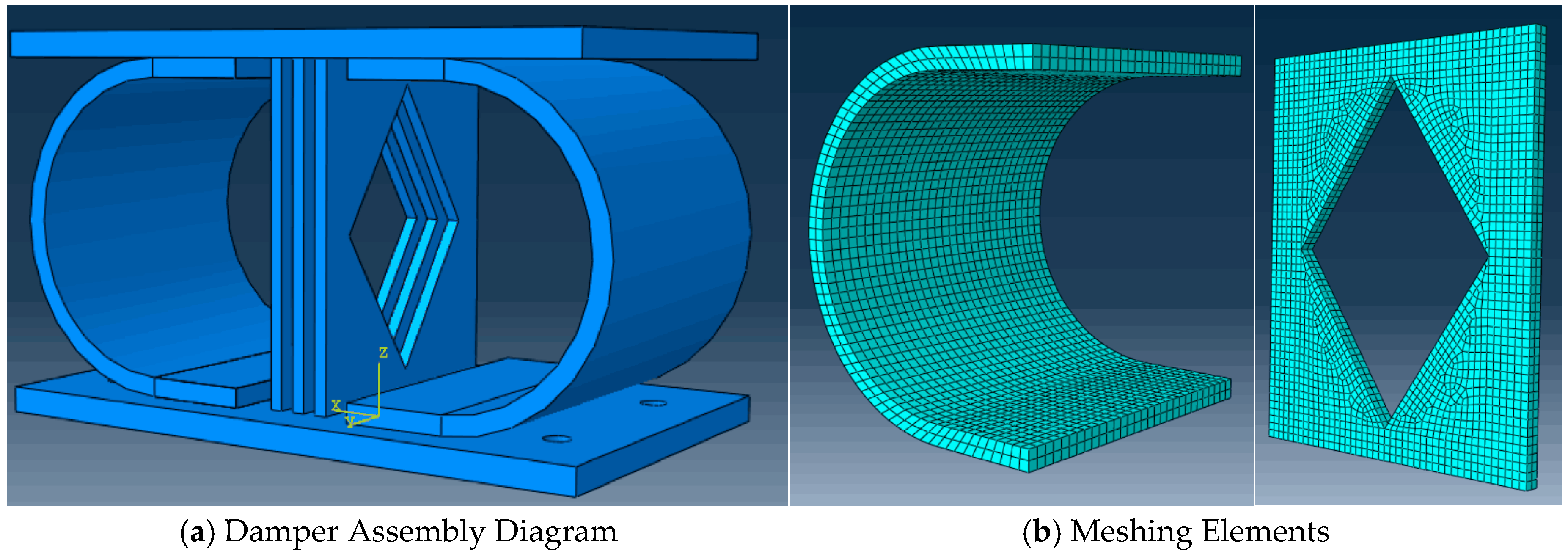
The design of the CSD builds on prior advancements in U-shaped damper technology. Experimental studies [9] demonstrated that U-shaped combined steel dampers (UCSDs) enhance energy dissipation and reduce seismic fragility in bridge systems. Prior research [35] highlighted the benefits of hybrid configurations (e.g., combining U-shaped plates with rectangular plates) for yield displacement control. Additional work [34] further identified thickness optimization as a critical factor in mitigating fracture risk in seismic isolation systems. Leveraging these insights, the CSD is composed of a central energy-dissipating plate assembly and upper/lower connecting steel plates, as shown in Figure 2. The energy-dissipating assembly consists of three parallel-arranged hollow rhombic steel plates positioned symmetrically about the central axis, flanked by bilateral U-shaped plates with inward-facing notches. This configuration facilitates energy dissipation primarily through flexural deformation of the curved segments in the metallic U-plates, where the arc-shaped portions undergo bending deformation to achieve hysteretic energy absorption. Material selection prioritizes functional differentiation: Q235 steel (yield strength: 235 MPa) is used for energy-dissipating components, whereas Q345 steel (yield strength: 345 Mpa) ensures structural stability in non-dissipative regions [36]. Finite element validation in ABAQUS confirms the CSD’s synergistic energy dissipation through sequential activation of U-shaped and diamond plates [28], with that of conventional dampers [29]. This design effectively addresses the limitations of traditional MSDs in terms of load-bearing and multi-directional energy dissipation [30].

2.3. Finite Element Modeling Framework

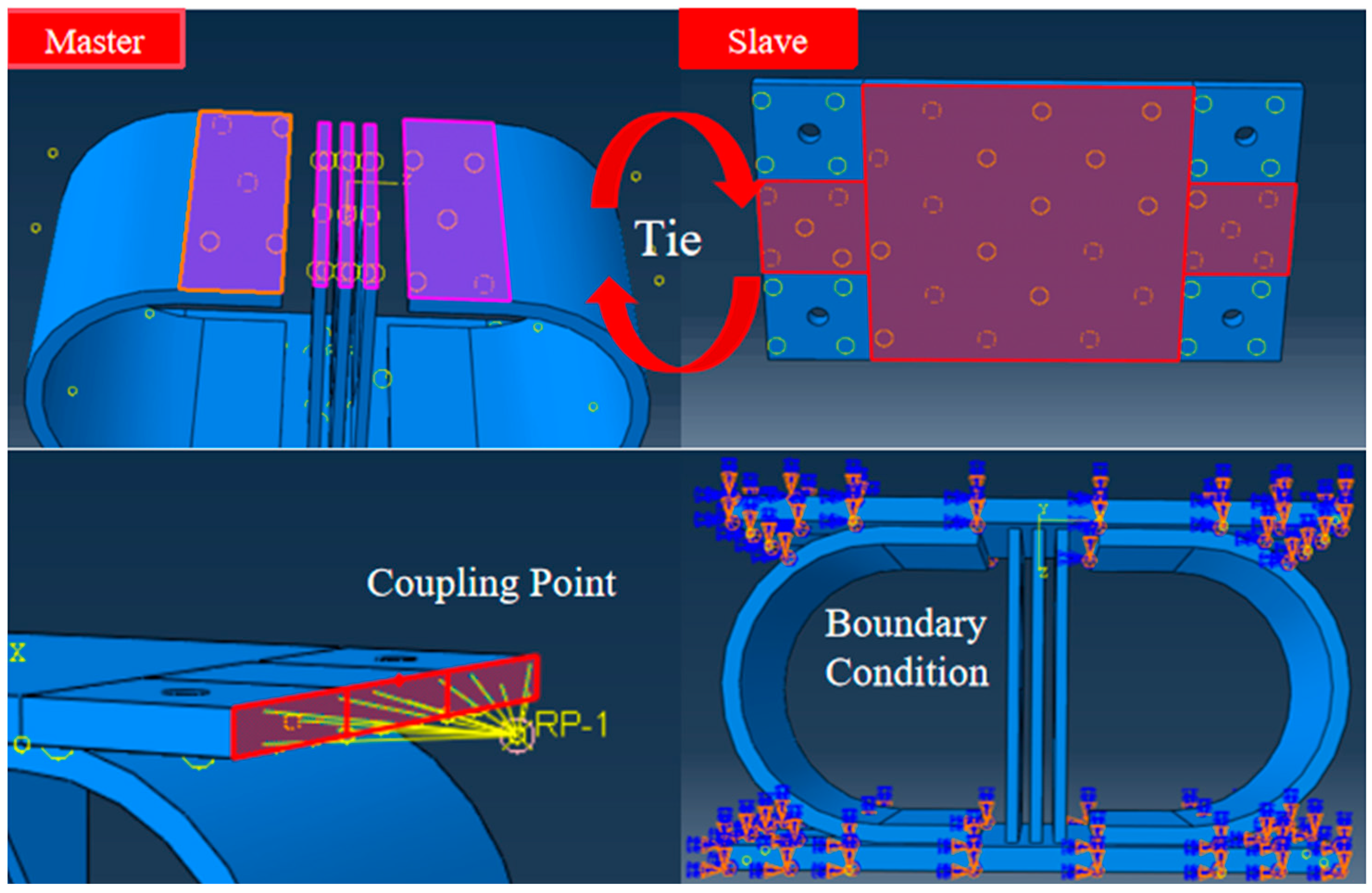
The finite element model framework incorporates constitutive models for the Q235 and Q345 steels, with bilinear kinematic hardening assigned to the Q235 steel to simulate post-yield behavior. Welds between components are omitted because of their negligible impact on global hysteresis, whereas auxiliary restraints are idealized as rigid constraints. The Newton–Raphson method was implemented in ABAQUS 2022, with convergence verified through residual force and displacement correction criteria. Following an initial analysis with coarse mesh configurations, progressive grid refinement was performed until the results variation between successive meshes fell below 5%, at which point the mesh was considered sufficiently refined. The meshing of the central energy-dissipating plate is shown in Figure 2. A 5 mm tetrahedral element grid is adopted to balance computational accuracy and efficiency. The U-shaped plate uses 8 mm hexahedral elements, with local refinement to 5 mm in the stress concentration regions, whereas the connecting plates employ a 10 mm structured mesh. As shown in Figure 3, surface-to-surface tie constraints bind energy-dissipating components to connecting plates, with master-slave pairs defined on the basis of the stiffness hierarchy. Displacement-controlled cyclic loading is applied at the upper plate’s reference point (RP-1) through a coupling mechanism, following a multi-stage protocol (0–60 mm) to capture both elastic and plastic response regimes. The boundary conditions, including full fixation of the lower plate and X-axis displacement constraints on the upper plate, are visually summarized.

2.4. Analysis of Deformation Modes and Hysteretic Performance Evaluation

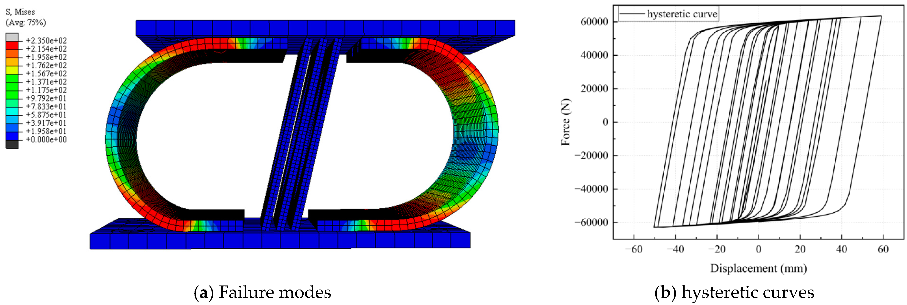
As shown in Figure 4, the FEM simulation of the CSD reveals that the maximum equivalent stress is concentrated in the bending segment and connection ends, indicating potential plastic deformation and low-cycle fatigue failure due to exceeding the material yield strength. Sub-high stress bands in transition zones form continuous stress transfer paths with the main bending area, where cracks may propagate along geometric discontinuities. The steep stress gradient at the connection ends suggests that tear risk occurs near bolt holes or welds, while drastic stress variations in thin-walled regions may trigger material delamination or micro-damage accumulation.
The CSD exhibits a full hysteresis loop without pinching effects, as demonstrated in Figure 4. The quantitative metrics reveal an energy dissipation coefficient (Ed) of 1.82 ± 0.15 across loading cycles and an equivalent damping ratio (ξeq) of 12.7% at the maximum displacement (60 mm). The ductility ratio (μ) reaches 5.3, surpassing that of conventional U-dampers (μ < 4.0). Parametric analysis revealed two distinct dissipation phases: initial yielding (0–10 mm) dominated by U-plate deformation (Ed = 0.95) and subsequent hollow diamond plate activation (10–60 mm), resulting in Ed > 1.5. These results validate the CSD’s hierarchical energy dissipation mechanism and its ability to mitigate displacement amplification risks inherent in traditional dampers.

3. Seismic Analysis of the HSR Track–Bridge System Integrated with CSD

3.1. Introduction

High-speed railway (HSR) bridges exhibit unique dynamic interactions that are distinct from those of conventional highway bridges because of their integration with ballastless track systems. The continuous track–bridge coupling amplifies the vibration transmission complexity [37,38], where localized damage—such as bearing failure or girder displacement—can cascade into systemic risks, compromising structural integrity and train operational safety (Figure 5). This interdependence necessitates holistic modeling of the HSR vehicle–track–bridge–damper (HSRVTBD) system [39] under seismic excitation. Building on Chapter 2′s validated CSD design, this chapter establishes a spatial finite element model (FEM) in OpenSees to quantify CSD’s efficacy in mitigating seismic responses across coupled subsystems.

3.2. Finite Element Modeling of the HSRVTBD System

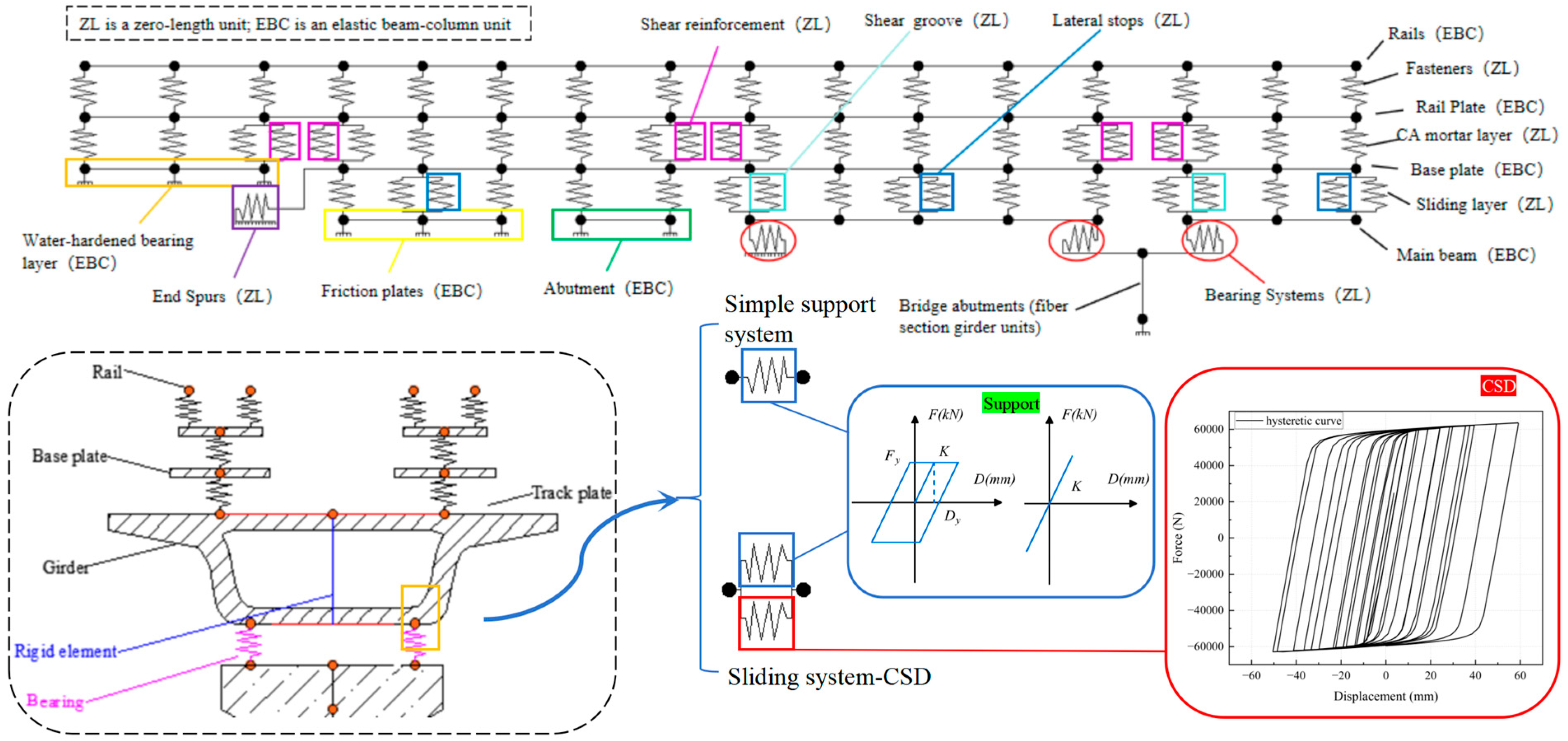
The analysis targets a 5-span simply supported girder bridge with a CRTS II slab track, featuring uniform pier heights (14 m) and 32.6 m spans. The transition zones (50 m) and embankment sections (90 m) flank the bridge ends to simulate realistic boundary conditions [40]. Figure 6 shows a partial finite element model of the high-speed railway track–bridge system. The system consists of two parts: the bridge structure and the track structure. The bridge structure includes the main girder, bearings, piers, and abutments. The composition of the track structure varies depending on its installation location. Longitudinal components along the track alignment comprise rails, track slabs, fasteners, and CA mortar layers. For track structures on bridges, additional elements include base plates, sliding layers, shear reinforcement, shear keys, and lateral restraint blocks. The track structure in the bridge–subgrade transition zone incorporates base plates, sliding layers, end studs, and friction plates. Subgrade sections utilize hydraulically stabilized base layers to support the track structure. Theoretical and experimental analyses confirm that rails, track slabs, base plates, and friction plates generally remain elastic under seismic loads, thus modeled as elastic beam elements. Interlayer connectors such as fasteners, CA mortar layers, sliding layers, shear keys, shear reinforcement, and lateral restraint blocks are simulated using zero-length elements [41].
The main girder, a 32.6 m span prestressed concrete box girder with a single-cell cross-section, is detailed in Figure 7. The key dimensions include a girder height of 3.05 m, a top flange width of 12.6 m, and a bottom flange width of 5.5 m, conforming to the General Reference Drawing for Railway Engineering Construction. Abutments adopt a gravity-type design with longitudinal lengths of 2.5 m and 10 cm girder-abutment clearance. Elastic beam-column elements simulate the girder’s high shear stiffness and predominantly elastic seismic response.
The material properties of critical structural components, including the concrete grade, steel reinforcement, and interfacial connections, are rigorously calibrated against design codes and experimental data (Table 1) [42]. For example, the main girders (C50 concrete) and piers (C40 concrete) employ the Concrete01 and Concrete04 models to distinguish cover and confined core behaviors, while the Q345 steel reinforcement follows the Giuffre–Menegotto–Pinto kinematic hardening law.
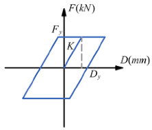
Interlayer connection mechanics, which are pivotal for track–bridge interaction accuracy, are defined through nonlinear spring elements (Table 2) [9,41,42]. Fasteners (WJ-8 type) exhibit horizontal yield forces of 15 kN with ideal elastoplasticity, while sliding layers combine Coulomb friction (μ = 0.2) and compression-only vertical springs (1.4 × 10⁶ kN/mm). Shear keys, which are essential for longitudinal force transfer, are modeled with elastic-perfectly plastic behavior (yield displacement: 0.12 mm, stiffness: 1 × 10⁶ kN/mm).
The CSD, validated in Chapter 2, is implemented as nonlinear springs between piers and girders, with its hysteresis behavior embedded via user-defined material subroutines [43].

3.3. Ground Motion Selection and Spectral Matching

Appropriate ground motion records serve as a critical foundation for conducting nonlinear time history analyses. Currently, three primary methodologies are employed for selecting ground motion records: seismological parameter-based approaches, target spectrum-based methods, and most unfavorable earthquake-based criteria. To capture the inherent variability of ground motions, 40 ground motion records were extracted from the Pacific Earthquake Engineering Research Center (PEER) database. These records were scaled to match a site-specific design spectrum (PGA: 0.1 g–0.6 g) [30], ensuring intensity consistency (Intensity Measure, IA = 0.8–1.2) while preserving frequency content diversity. Table 3 summarizes key parameters of the selected records, including magnitude, epicentral distance, and peak ground acceleration. Figure 8 compares the adjusted response spectra with the target spectrum, demonstrating deviations within 10% across the dominant frequency range (0.5–10 Hz) [34]. Pulse-like ground motions require focused attention on instantaneous failure mechanisms, whereas non-pulse motions necessitate mitigation of cumulative damage. This ground motion suite incorporates both strong velocity pulse and non-pulse events to account for potential extreme scenarios. The input ground vibrations were assumed to be uniformly distributed at all structural supports, with the ground motion direction defined as transverse.
Building upon the comprehensive finite element model of the HSRVTBD system established in this chapter—which integrates multi-component realism (track–bridge interaction, CSD nonlinearity) and validated material laws (concrete, steel, interfacial connections)—nonlinear time history analyses were conducted. These analyses quantitatively evaluate the effectiveness of CSD in mitigating girder displacements, fastener forces, and track-slab accelerations. By synergizing design specifications (e.g., general reference diagrams) with advanced numerical techniques, this model advances seismic assessment methodologies for HSR infrastructure, particularly in seismically active regions requiring stringent displacement tolerances.

4. Seismic Mitigation Efficacy of CSD Dampers in HSR Bridge–Track Systems

4.1. Component-Level Deformation Analysis via MATLAB Visualization

The seismic performance of an HSR bridge–track system (BTS) retrofitted with combined steel dampers (CSDs) is systematically evaluated through MATLAB R2024b-driven data visualization. Comparative analyses between the baseline system (BTS) and the retrofitted system (BTS-CSD) focus on eight critical components, quantifying deformation reductions and identifying force redistribution patterns.
The assessment of structural safety status conventionally adopts peak response as the key indicator for evaluating component exceedance. To simplify the description, the mean value of lateral peak response of components considering all ground motion components was adopted to assess structural safety status.
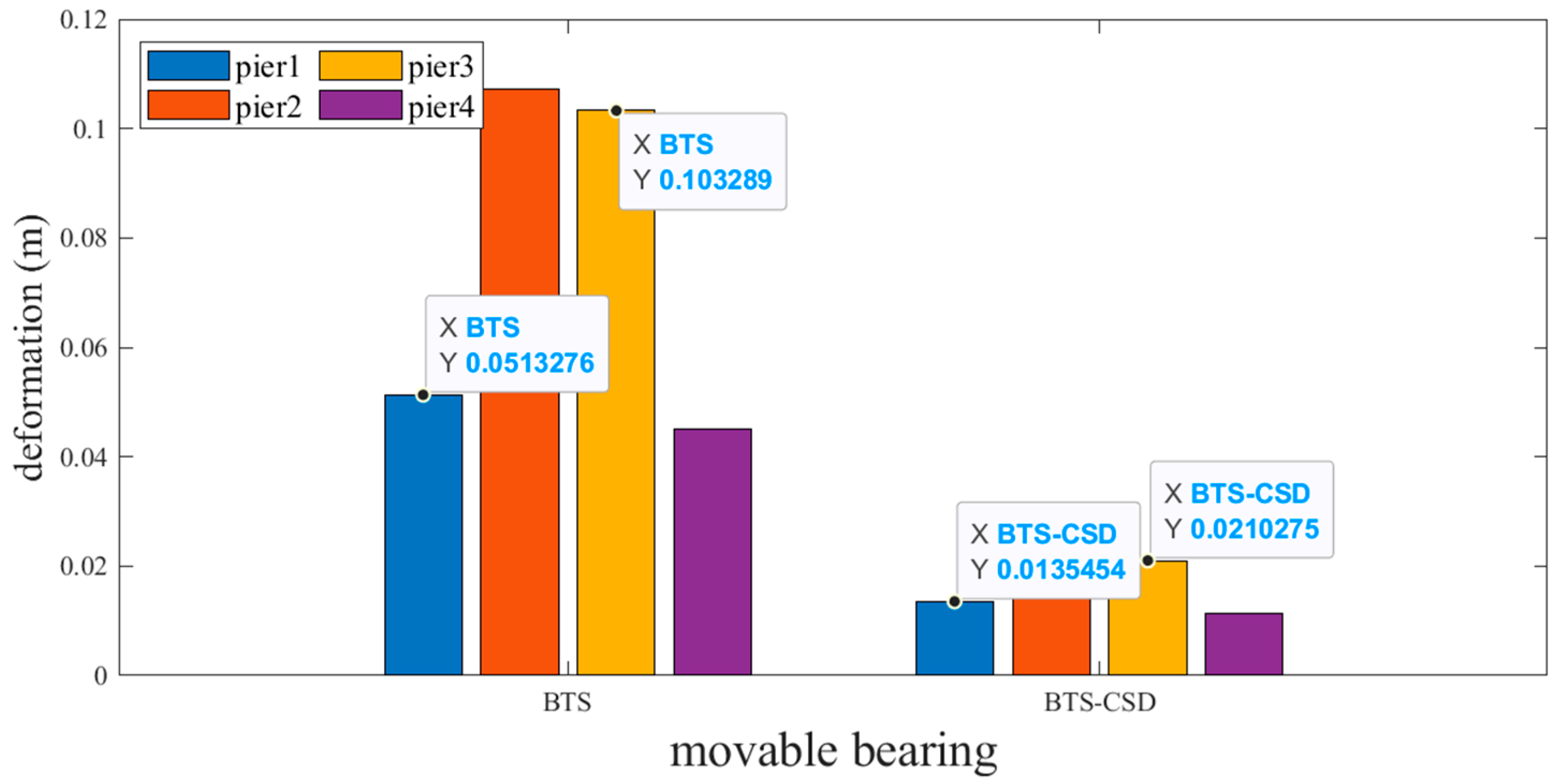
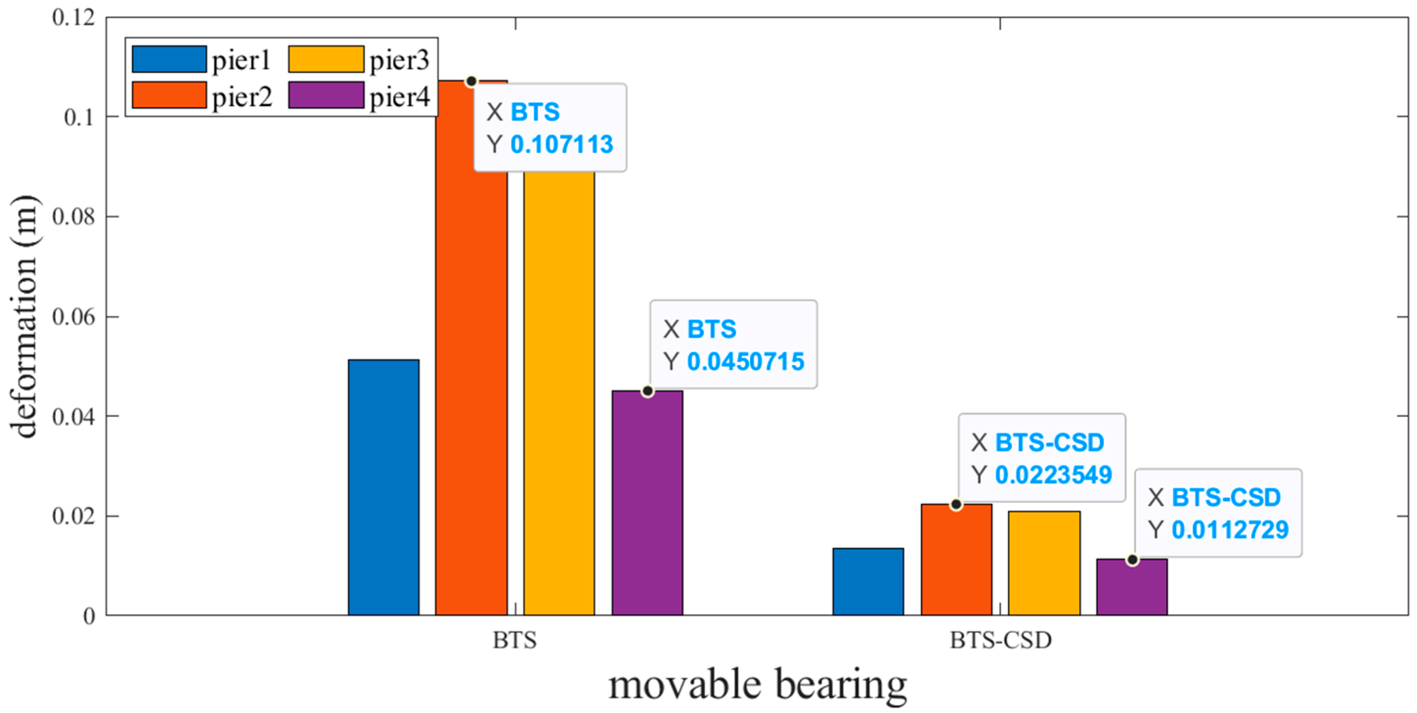
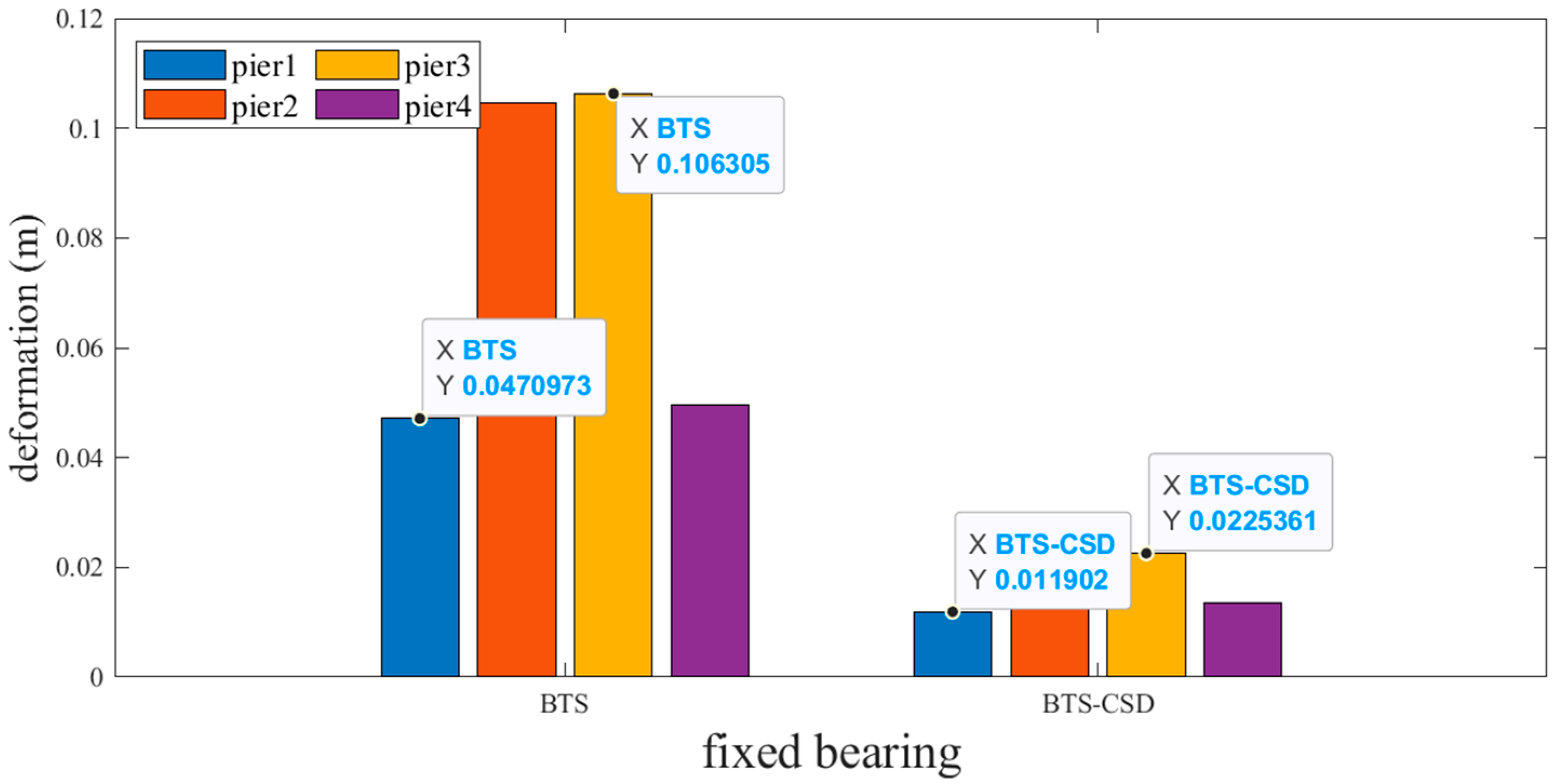
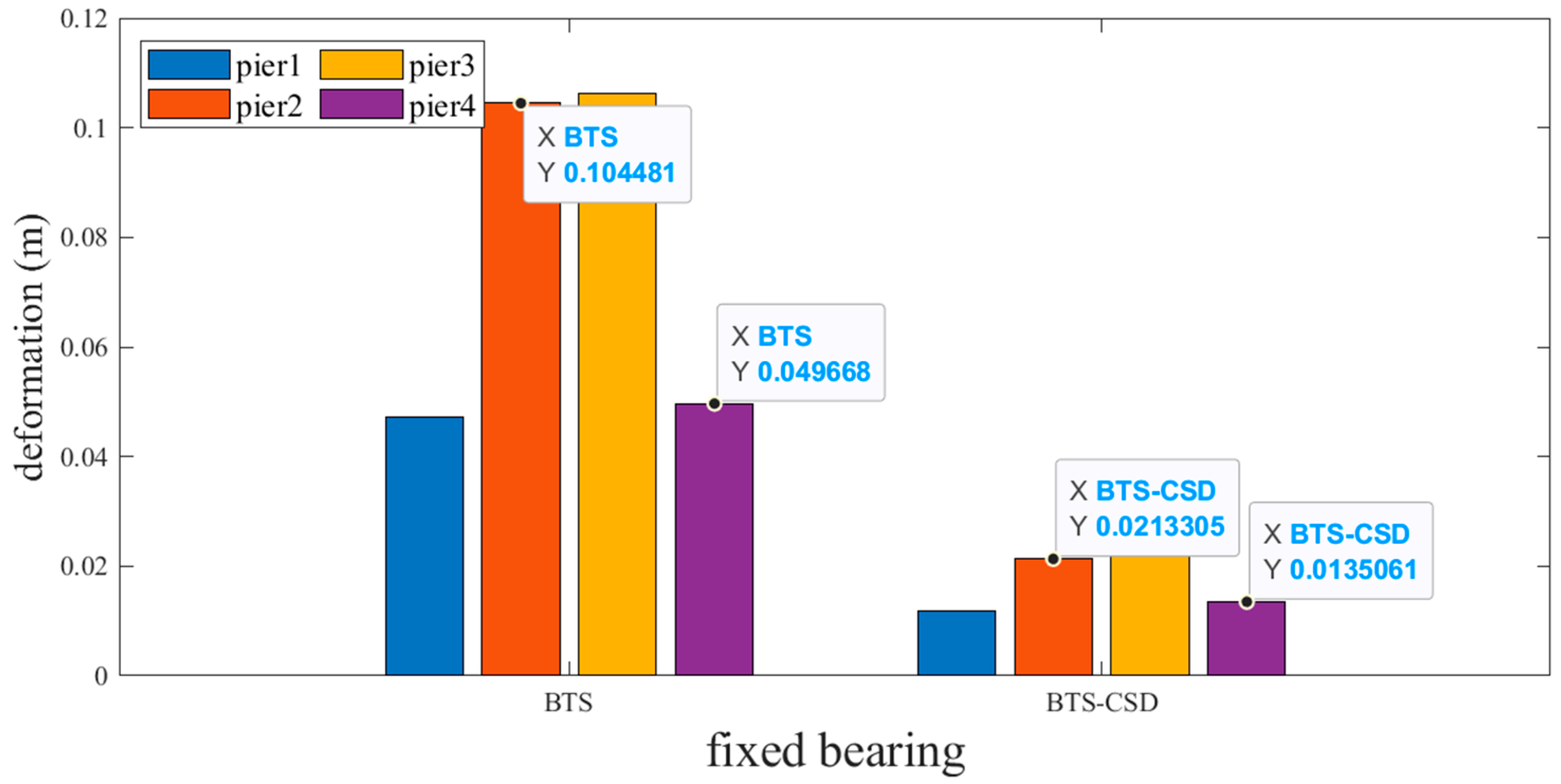
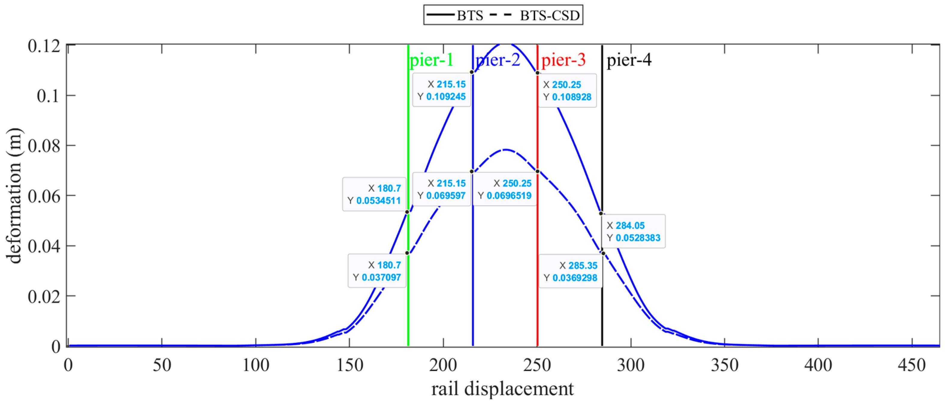
Sliding and fixed bearings exhibit the most pronounced improvements. Figure 9 and Figure 10 reveal that CSD implementation reduces sliding bearing deformation by 73.7% (Pier 1: 0.0514 m → 0.0134 m), 79.2% (Pier 2), 79.6% (Pier 3), and 74.9% (Pier 4), with analogous trends observed for fixed bearings (Figure 11 and Figure 12). Specifically, the fixed-bearing deformation decreases by 74.7% at Pier 1 (0.0471 m → 0.0119 m) and 72.8% at Pier 4 (Table 4 and Table 5). This uniform reduction (>70% across all piers) underscores CSD’s efficacy in restraining lateral displacements at bearing interfaces while maintaining torsional equilibrium.
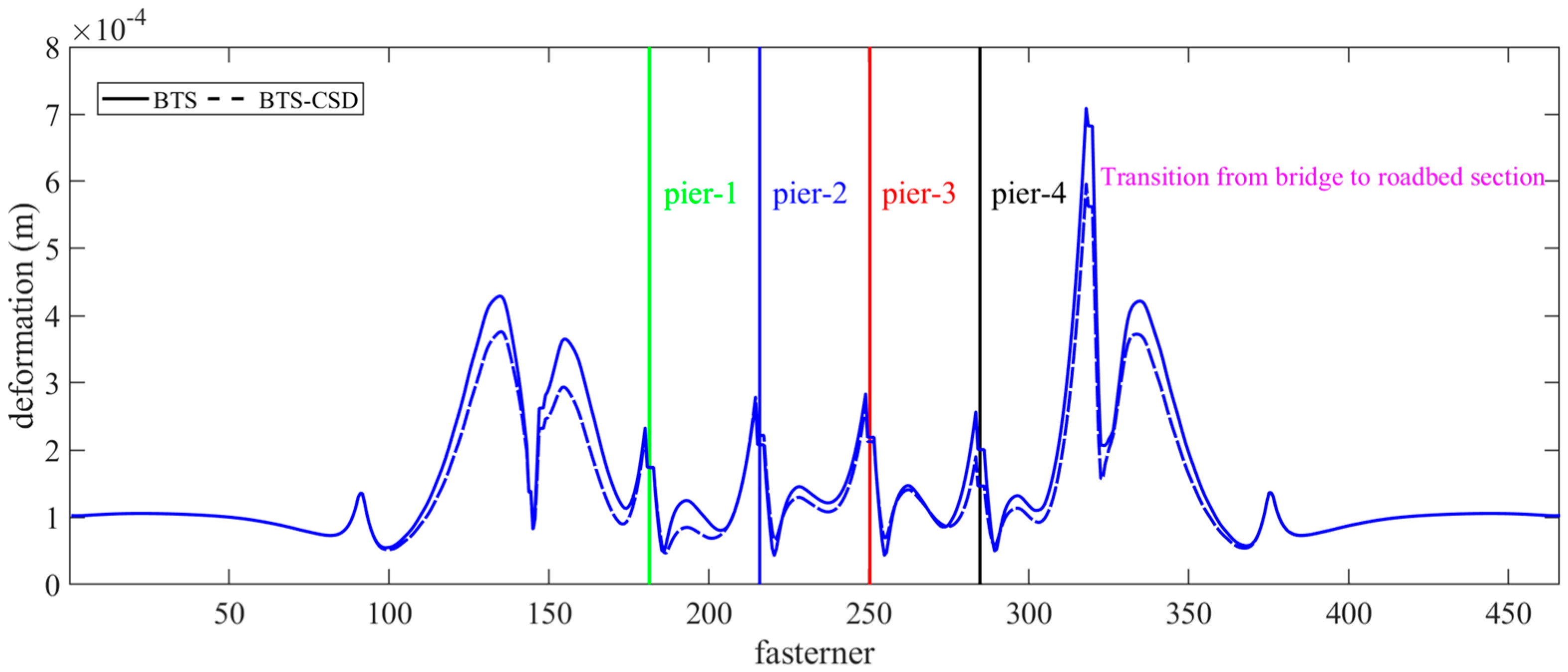
The deformation of fasteners is recognized as critical to maintaining track alignment accuracy, with a 30–35% reduction in deformation magnitude observed specifically within stress concentration zones (bridge–subgrade transition sections), serving as localized peak values (Figure 13). Detailed analysis attributes residual deformations to design limitations (suboptimal fastener geometry) [44], material degradation (fatigue-induced stiffness loss), and environmental effects (thermal preload relaxation). These insights highlight the need for integrated retrofitting strategies that combine CSD installation with fastener geometry optimization.
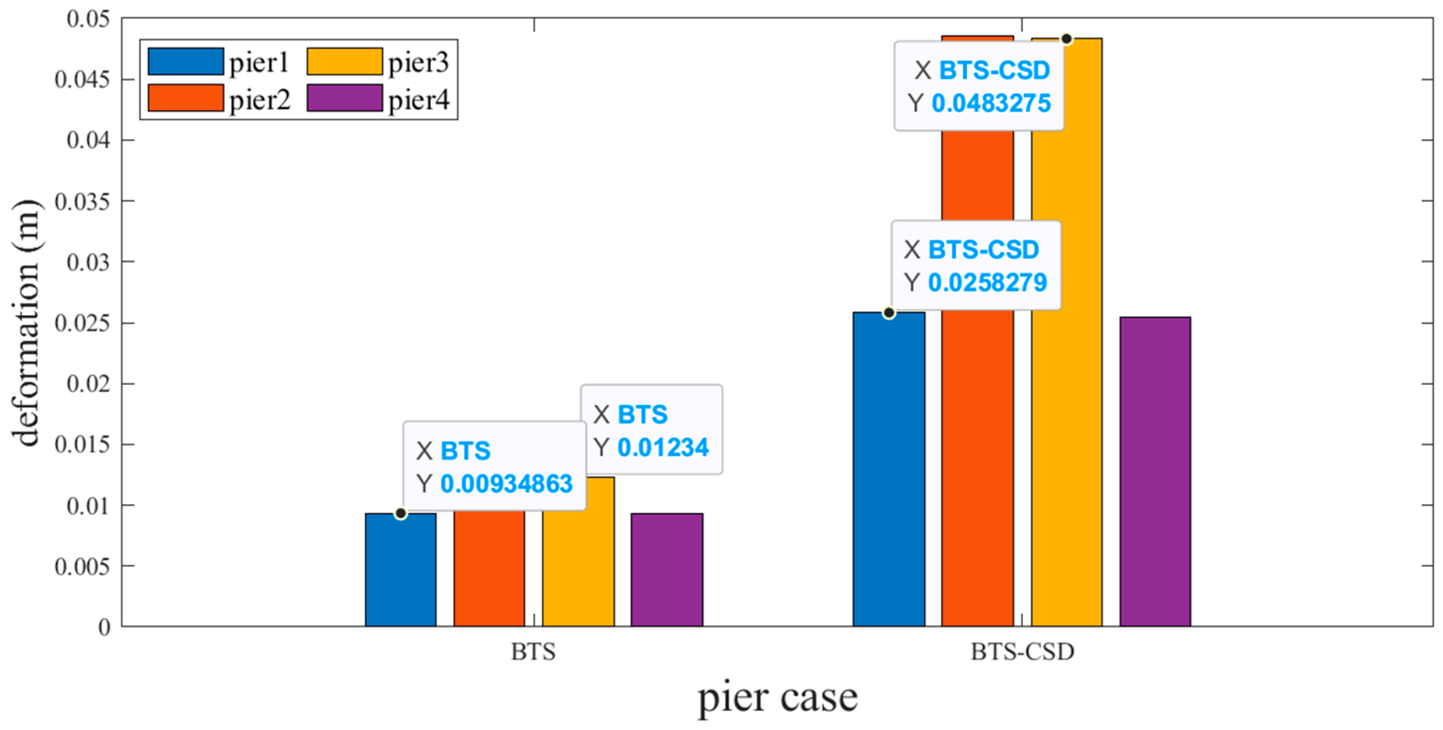
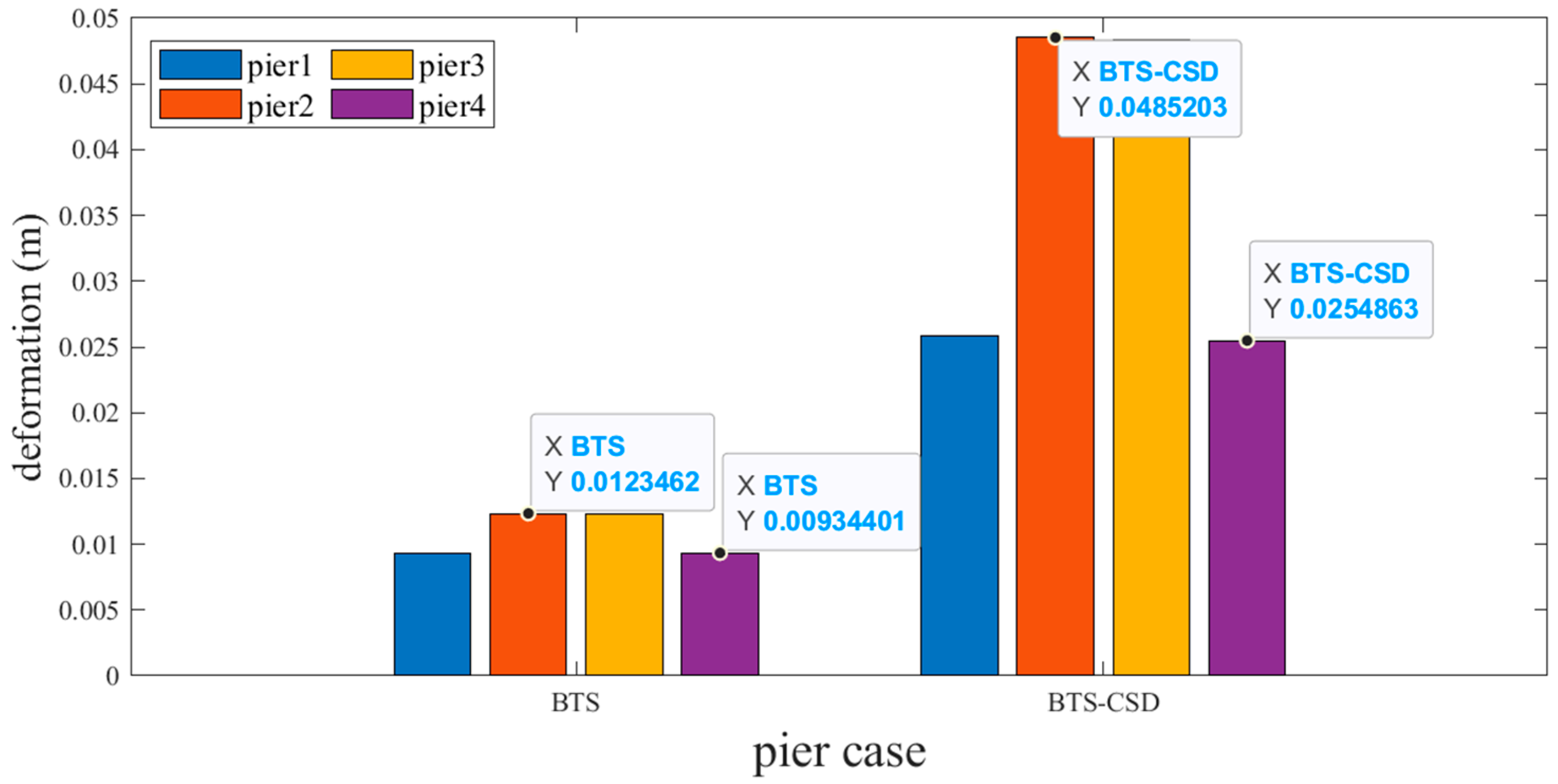
However, the experience of a counterintuitive 12–18% deformation increase occurs post-CSD installation (Figure 14 and Figure 15). For example, Pier 1 abutment deformation increases from 0.00935 m (BTS) to 0.0258 m (BTS-CSD). This phenomenon may stem from CSD-induced force redistribution, which transfers partial seismic energy from the superstructure to the substructure. Despite increased displacements, stress levels remain within 65% of yield thresholds, ensuring substructure safety.
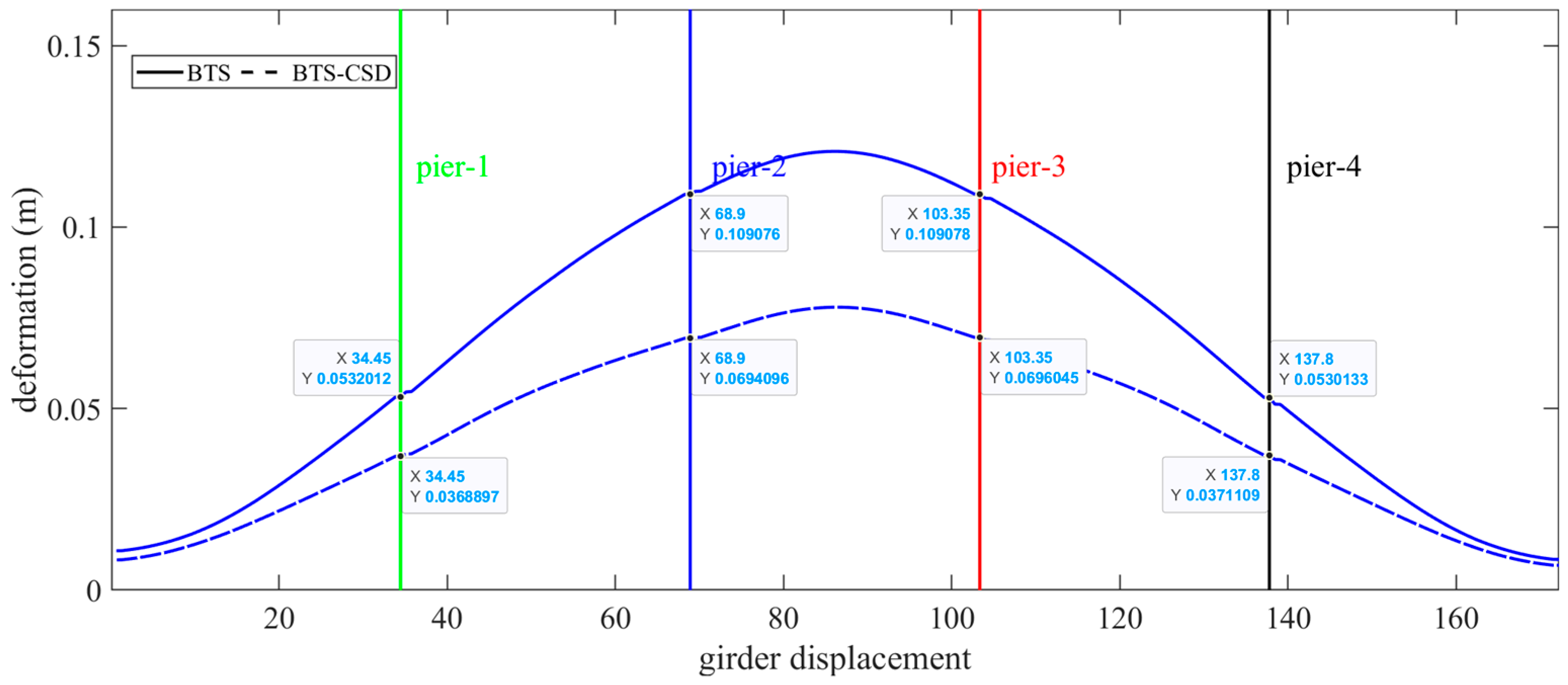
The main girders and bridge rails benefit significantly from CSD integration. Figure 16 and Figure 17 illustrate parallel displacement reductions: the main girders decrease by 30.6% (Pier 1), 36.4% (Pier 2), 36.2% (Pier 3), and 30.1% (Pier 4), while bridge rails exhibit comparable improvements (30.5% at Piers 1 to 36.3% at Piers 2) (Table 6 and Table 7). These results validate CSD’s dual role in safeguarding structural integrity and operational stability.
Shear key performance further corroborates CSD’s effectiveness. Position 5 corresponds to the subgrade connection zone where shear keys exhibit amplified dynamic responses. Mitigating these responses is critical to ensuring the structural integrity of the bridge–track system; therefore, this specific area has been selected as the focal point for detailed analysis in the present study. Figure 18 shows a 48.5% deformation reduction at Position 5 (0.33 mm → 0.17 mm), mitigating interface shear stresses and preserving track alignment under seismic loads.

4.2. Synthesis of Seismic Retrofitting Outcomes

MATLAB-driven analytics establish CSD as a transformative solution for HSR seismic retrofitting. The key findings include the following: (1) Critical Components: Sliding/fixed bearing deformations are reduced by 73–80%, ensuring lateral stability; (2) Operational Elements: Fastener, girder, and rail displacements are decreased by 30–36%, enhancing operational safety; and (3) Force Redistribution Trade-offs: Moderate abutment deformation increases (<20%) remain within elastic limits.
The engineering implications emphasize three actionable strategies: (1) stress concentration mitigation, which involves reinforce fastener zones at bridge–roadbed transitions via high-cycle fatigue-resistant alloys; (2) CSD deployment prioritization, which involves target piers with the highest baseline bearing displacements (Piers 2–3) for maximum efficacy; and (3) monitoring protocols, which implement real-time deformation sensors at abutments to track force redistribution effects.

5. Conclusions

This study evaluated the seismic performance of a combined steel damper (CSD) integrated into a 5-span CRTS II-track high-speed railway (HSR) bridge system. Through finite element model and nonlinear time-history analyses, the following conclusions are drawn:
(1) Hysteretic Performance of CSD. The proposed CSD, which integrates U-shaped and hollow diamond steel plates, exhibits full hysteresis loops without pinching effects, achieving an energy dissipation coefficient of 1.82 and an equivalent damping ratio of 12.7%. This validates its superior energy dissipation capacity under cyclic loading;
(2) System-level seismic mitigation. CSD implementation reduces critical component deformations by 73–80% for sliding/fixed bearings by 30–36% for fasteners, main girders, and bridge rails and by 48.5% for shear keys. The observed 12% to 18% increase in abutment deformation may be attributed to force redistribution mechanisms, while the stress level remains below 65% of the yield strength threshold, ensuring structural integrity within safe limits.

Author Contributions

Conceptualization, L.J.; Methodology, M.L.; Software, M.L.; Formal analysis, M.L. and J.H.; Investigation, M.L. and J.H.; Data curation, J.H.; Writing—original draft, M.L.; Writing—review & editing, L.J. and J.H.; Visualization, J.H.; Supervision, L.J.; Project administration, L.J.; Funding acquisition, L.J. All authors have read and agreed to the published version of the manuscript.

Funding

This research was financially supported by the National Key Research and Development Program of China (2022YFC3004304).

Institutional Review Board Statement

Not applicable.

Informed Consent Statement

Not applicable.

Data Availability Statement

The original contributions presented in this study are included in the article. Further inquiries can be directed to the corresponding author.

Conflicts of Interest

The authors declare no conflict of interest.

References

  1. Jiang, L.; Zhong, B.; Zhang, Y.; Zhou, W.; Lai, Z. A Novel Seismic-Resistant Design for Track Structures in the Bridge-Embankment Transition Zone of Multi-Span High-Speed Railways Simply Supported Bridges. Eng. Struct. 2025, 324, 119349. [Google Scholar] [CrossRef]
  2. Duan, H.; Jiang, L.; Wen, T.; Jiang, L. An Improved Interlayer Area Damage Model for Seismic Damage Assessment of a High-Speed Railway Long-Span Arch Bridge-Track System. SOIL Dyn. Earthq. Eng. 2024, 184, 108811. [Google Scholar] [CrossRef]
  3. Zhou, Y.; Gao, C.; Yang, S.; Guo, W.; Jiang, L. Seismic Fragility Analysis of Reinforced Concrete Simply Supported Girder Bridges Resting on Double-Column Piers for High Speed Railway. Buildings 2024, 14, 3072. [Google Scholar] [CrossRef]
  4. Zhou, W.; Xiong, L.; Jiang, L. Multi-Parameter Seismic Fragility Analysis of High-Speed Railway Track-Bridges: Embracing Structural and Earthquake Uncertainties. Int. J. Struct. Stab. Dyn. 2024, 2630001. [Google Scholar] [CrossRef]
  5. Zhou, W.; Wu, L.; Zhong, T.; Jiang, L.; Liu, S. Impact of Vertical Girder Deformations on the High-Speed Train Operation Performance. Struct. Infrastruct. Eng. 2024, 1–17. [Google Scholar] [CrossRef]
  6. Zhao, L.; Zhou, L.; Zhang, G.; Wei, T.; Mahunon, A.; Jiang, L.; Zhang, Y. Experimental Study of the Temperature Distribution in CRTS-II Ballastless Tracks on a High-Speed Railway Bridge. Appl. Sci. 2020, 10, 1980. [Google Scholar] [CrossRef]
  7. Jiang, L.; Duan, H.; Wen, T.; Jiang, L. Effects of Near-Fault Pulse-like Ground Motions and Pulse Parameters on a High-Speed Railway Long-Span Arch Bridge-Track System. J. Bridge Eng. 2025, 30, 04024112. [Google Scholar] [CrossRef]
  8. Jiang, L.; Yu, K.; Jiang, L.; Wen, T.; Hu, Y.; Pang, L. Effects of Shear Panel Dampers on Seismic Response Mitigation of High-Speed Railway Simply Supported Bridge-Track System under Far-Field and near-Field Ground Motions. Arch. Civ. Mech. Eng. 2023, 23, 93. [Google Scholar] [CrossRef]
  9. Jiang, L.; Liu, J.; Wen, T.; Jiang, L.; Yan, Y.; He, C. Damage Dispersion Study of High-Speed Railway Track-Bridge System with the UCSD Considering Train Effects. Structures 2024, 68, 107213. [Google Scholar] [CrossRef]
  10. Lai, Z.; Jiang, L.; Chen, Y.; Wei, B. An Improved Model for the Nonlinear Simulation of the High-Speed Vehicle-Track-Bridge Coupling System under Seismic Shaking. Earthq. Eng. Struct. Dyn. 2024, 53, 3775–3797. [Google Scholar] [CrossRef]
  11. Zhou, W.; Xiao, J.; Liu, S.; Jiang, L.; Yu, J.; Zu, L.; Wu, L.; Ren, Z. Analysis of Key Influencing Factors of Track Dynamic Irregularity Induced by Earthquakes in the High-Speed Railway Track-Bridge System. Int. J. Struct. Stab. Dyn. 2024, 24, 2450246. [Google Scholar] [CrossRef]
  12. Zhou, W.; Xiong, L.; Jiang, L.; Zhong, B. Innovative Approaches in High-Speed Railway Bridge Model Simplification for Enhanced Computational Efficiency. J. Cent. South Univ. 2024, 31, 4203–4217. [Google Scholar] [CrossRef]
  13. Wei, B.; Wang, P.; Yan, B.; Jiang, L.; He, X. Parameter Optimization of Damper-Friction Isolation Systems Using Concave Friction Distribution. J. Vibroengineering 2016, 18, 1668–1682. [Google Scholar] [CrossRef]
  14. Wen, T.; Jiang, L.; Jiang, L.; Zhou, W.; Du, Y. Interlayer Area Damage Modeling and Damage-Based Seismic Fragility Analysis of High-Speed Railway Bridge and Track System. Eng. Struct. 2022, 272, 114989. [Google Scholar] [CrossRef]
  15. Zhou, W.; Xiong, L.; Jiang, L. New Parameter Updating Method for Bidirectional Simplified Seismic Models of High-Speed Railway Bridges. Structures 2025, 71, 107959. [Google Scholar] [CrossRef]
  16. Wen, T.; Duan, H.; Jiang, L.; Zhou, W.; Du, Y.; Jiang, L. Refined Probabilistic Seismic Demand Modeling of High-Speed Railway Bridge under near-Fault Hanging-Wall Effects and Velocity Pulse Effects by a Novel Ground Motion Selection Approach. Int. J. Struct. Stab. Dyn. 2024, 2650074. [Google Scholar] [CrossRef]
  17. Jiang, L.; Li, W.; Jiang, L.; Wang, Z.; Wen, T. Railway Alignment Optimization and Seismic Responses of High-Speed Railway Bridge Considering the Spatial Effects of Mountainous-Plateau. Int. J. Struct. Stab. Dyn. 2024, 2550170. [Google Scholar] [CrossRef]
  18. Wei, B.; Xiao, B.; Tan, H.; Yang, Z.; Jiang, L.; Yu, Y. Energy Response Analysis and Seismic Isolation Strategy Optimization of High-Speed Railway Bridge-Track System under Earthquake Action. Soil Dyn. Earthq. Eng. 2024, 186, 108917. [Google Scholar] [CrossRef]
  19. Liu, B.; He, C.; Lai, Z.; Jiang, L.; Li, D. Elastoplastic Bridge Deck Response Spectra of High-Speed Railway Simply-Supported Girder Bridge with CRTSII Track System. J. Cent. South Univ. 2024, 31, 4174–4186. [Google Scholar] [CrossRef]
  20. Zhao, H.; Wei, B.; Zhang, P.; Guo, P.; Shao, Z.; Xu, S.; Jiang, L.; Hu, H.; Zeng, Y.; Xiang, P. Safety Analysis of High-Speed Trains on Bridges under Earthquakes Using a LSTM-RNN-Based Surrogate Model. Comput. Struct. 2024, 294, 107274. [Google Scholar] [CrossRef]
  21. Wang, Z.; Jiang, L.; Jiang, L.; Zhou, W.; Du, Y. Seismic Response of High-Speed Railway Simple-Supported Girder Track-Bridge System Considering Spatial Effect at near-Fault Region. Soil Dyn. Earthq. Eng. 2022, 158, 107283. [Google Scholar] [CrossRef]
  22. Wen, T.; Jiang, L.; Jiang, L.; Jin, Z.; Du, Y.; Pang, L. Repair Cost Assessment of Longitudinal Continuous Ballastless Track Structure on High-Speed Railway Bridge with Spatially Distributed Interlayer Area Damage. Structures 2023, 57, 105157. [Google Scholar] [CrossRef]
  23. Wen, T.; Jiang, L.; Jiang, L.; Zhou, W.; Du, Y. Optimal Intensity Measure Selection in Incremental Dynamic Analysis: Methodology Improvements and Application to a High-Speed Railway Bridge. Bull. Earthq. Eng. 2024, 22, 2059–2083. [Google Scholar] [CrossRef]
  24. Liu, X.; Jiang, L.; Xiang, P.; Jiang, L.; Lai, Z. Safety and Comfort Assessment of a Train Passing over an Earthquake-Damaged Bridge Based on a Probability Model. Struct. Infrastruct. Eng. 2023, 19, 525–536. [Google Scholar] [CrossRef]
  25. Li, S.; Xiang, P.; Wei, B.; Zuo, C.; Jiang, L.; He, W. Interface Friction Effects on Scaling a Vertical Spring-Viscous Damper Isolation System in a Shaking Table Test. Structures 2021, 33, 1878–1891. [Google Scholar] [CrossRef]
  26. Tan, H.; Wei, B.; Wang, W.; Xiao, B.; Li, S.; Jiang, L. Influence of Pier Height and Ground Motion Parameters on Seismic Response and Energy Dissipation of Isolated Railway Bridges. Structures 2024, 68, 107236. [Google Scholar] [CrossRef]
  27. Wei, B.; Wang, P.; He, X.; Jiang, L. Seismic Response of Spring-Damper-Rolling Systems with Concave Friction Distribution. Earthq. Struct. 2016, 11, 25–43. [Google Scholar] [CrossRef]
  28. Guo, W.; Zeng, C.; Gou, H.; Hu, Y.; Xu, H.; Guo, L. Rotational Friction Damper’s Performance for Controlling Seismic Response of High Speed Railway Bridge-Track System. CMES-Comput. Model. Eng. Sci. 2019, 120, 491–515. [Google Scholar] [CrossRef]
  29. Isacchi, G.; Ripamonti, F.; Corsi, M. Innovative Passive Yaw Damper to Increase the Stability and Curve-Taking Performance of High-Speed Railway Vehicles. Veh. Syst. Dyn. 2023, 61, 2273–2291. [Google Scholar] [CrossRef]
  30. Kahya, V.; Araz, O. A Simple Design Method for Multiple Tuned Mass Dampers in Reduction of Excessive Vibrations of High-Speed Railway Bridges. J. Fac. Eng. Archit. Gazi Univ. 2020, 35, 607–618. [Google Scholar] [CrossRef]
  31. Luu, M.; Martinez-Rodrigo, M.D.; Zabel, V.; Koenke, C. Semi-Active Magnetorheological Dampers for Reducing Response of High-Speed Railway Bridges. Control Eng. Pract. 2014, 32, 147–160. [Google Scholar] [CrossRef]
  32. Moliner, E.; Museros, P.; Martinez-Rodrigo, M.D. Retrofit of Existing Railway Bridges of Short to Medium Spans for High-Speed Traffic Using Viscoelastic Dampers. Eng. Struct. 2012, 40, 519–528. [Google Scholar] [CrossRef]
  33. Tell, S.; Leander, J.; Andersson, A.; Ulker-Kaustell, M. Probability-Based Evaluation of the Effect of Fluid Viscous Dampers on a High-Speed Railway Bridge. Struct. Infrastruct. Eng. 2021, 17, 1730–1742. [Google Scholar] [CrossRef]
  34. Jin, T.; Liu, Z.; Sun, S.; Ren, Z.; Deng, L.; Yang, B.; Christie, M.D.; Li, W. Development and Evaluation of a Versatile Semi-Active Suspension System for High-Speed Railway Vehicles. Mech. Syst. Signal Process. 2020, 135, 106338. [Google Scholar] [CrossRef]
  35. Martinez-Rodrigo, M.D.; Lavado, J.; Museros, P. Dynamic Performance of Existing High-Speed Railway Bridges under Resonant Conditions Retrofitted with Fluid Viscous Dampers. Eng. Struct. 2010, 32, 808–828. [Google Scholar] [CrossRef]
  36. Luu, M.; Martinez-Rodrigo, M.D.; Zabel, V.; Koenke, C. H∞ Optimization of Fluid Viscous Dampers for Reducing Vibrations of High-Speed Railway Bridges. J. Sound Vib. 2014, 333, 2421–2442. [Google Scholar] [CrossRef]
  37. Xu, X.; Chen, X.; Hu, H.; Zhou, X.; Cheng, M.; Sun, L.; Li, X. Energy Dissipation and Seismic Response Reduction System for High-Speed Railway Bridges Based on Multiple Performance Requirements. Eng. Struct. 2024, 307, 117919. [Google Scholar] [CrossRef]
  38. Wang, X.; Liu, B.; Di Gialleonardo, E.; Kovacic, I.; Bruni, S. Application of Semi-Active Yaw Dampers for the Improvement of the Stability of High-Speed Rail Vehicles: Mathematical Models and Numerical Simulation. Veh. Syst. Dyn. 2022, 60, 2608–2635. [Google Scholar] [CrossRef]
  39. Alehashem, S.M.S.; Ni, Y.Q.; Liu, X.Z. A Full-Scale Experimental Investigation on Ride Comfort and Rolling Motion of High-Speed Train Equipped With MR Dampers. IEEE Access 2021, 9, 118113–118123. [Google Scholar] [CrossRef]
  40. Sang, H.; Zeng, J.; Gan, F.; Mu, J.; Qi, Y. A Study of Wheel Wear on a High-Speed Railway Motor Car. Proc. Inst. Mech. Eng. Part F J. Rail Rapid Transit 2023, 237, 80–92. [Google Scholar] [CrossRef]
  41. Ren, J.; Li, Q.; Ren, Z.; Yang, G. A New Hydraulic Damper Dynamics Model and the Availability on High Speed Vehicle Dynamics Investigation. Veh. Syst. Dyn. 2023, 61, 356–374. [Google Scholar] [CrossRef]
  42. Zhu, Q.K. Interaction Between Simply-Supported Beam Bridges and CRTS II Slab Ballastless Track in High-Speed Railways. Master’s Thesis, Central South University, Changsha, China, 2013. [Google Scholar]
  43. Hu, Z.; Song, D.; Zeng, Y.; Zhang, W. Analysis of the Service Life of Railway Hydraulic Dampers Considering Temperature and Loading. Proc. Inst. Mech. Eng. Part F J. Rail Rapid Transit 2021, 235, 3–11. [Google Scholar] [CrossRef]
  44. Zhang, Y.; Yang, X.; Liu, S. Design and Parameters Influence Analysis of Dynamic Vibration Absorber for Fastener Clips in High-Speed Railway. J. Vib. Control 2024, 30, 472–486. [Google Scholar] [CrossRef]
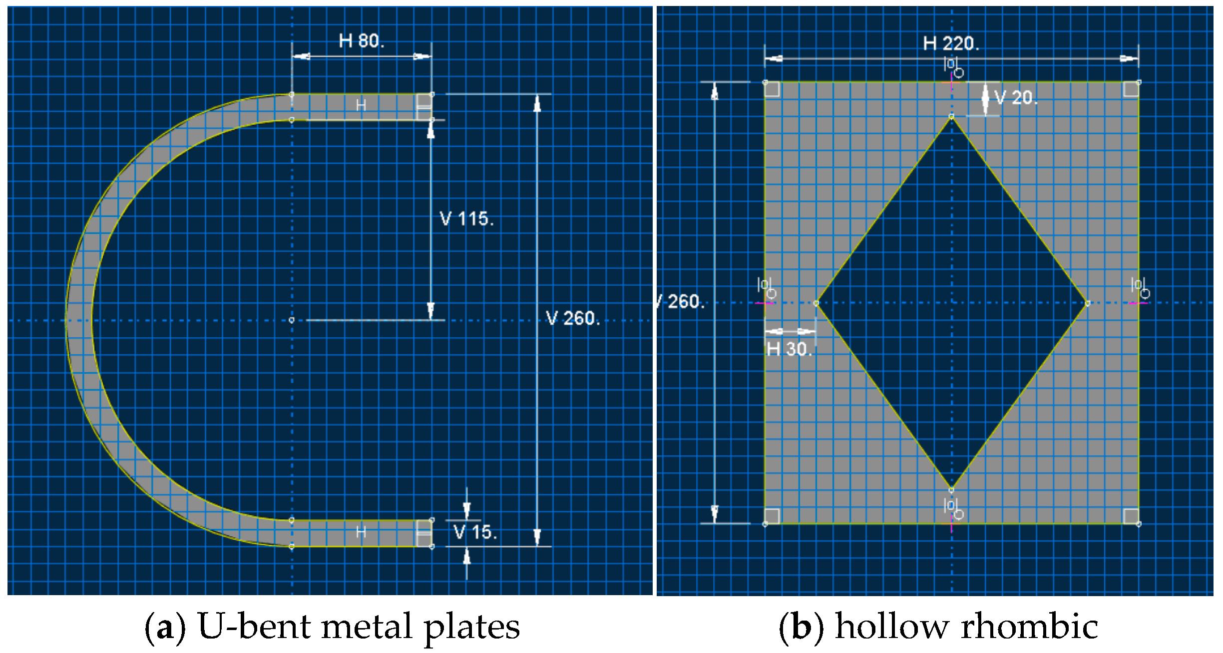
Figure 1. Dimensions of the hollow rhombic and U-bent metal plates.
Materials 18 02120 g001
Figure 2. Damper Assembly Diagram and Meshing Elements.
Materials 18 02120 g002
Figure 3. Finite element modeling process.
Materials 18 02120 g003
Figure 4. Finite element simulation results.
Materials 18 02120 g004
Figure 5. Schematic of HSRTTBS with CSD.
Materials 18 02120 g005
Figure 6. Schematic diagram of the finite element model of the HSRTTBDS.
Materials 18 02120 g006
Figure 7. Schematic diagram of the main girder and abutment cross-section.
Materials 18 02120 g007
Figure 8. Response spectra and grouping information for ground shaking records.
Materials 18 02120 g008
Figure 9. Comparison of BTS and BTS-CSD Deflections—Sliding Support Piers 1 and 3.
Materials 18 02120 g009
Figure 10. Comparison of BTS and BTS-CSD Deflections—Sliding Bearing Piers 2 and 4.
Materials 18 02120 g010
Figure 11. Comparison of BTS and BTS-CSD Deflections—Fixed Support Piers 1 and 3.
Materials 18 02120 g011
Figure 12. Comparison of BTS and BTS-CSD Deflections—Fixed Support Piers 2 and 4.
Materials 18 02120 g012
Figure 13. Comparison of BTS and BTS-CSD Deflections—Fasteners.
Materials 18 02120 g013
Figure 14. Comparison of BTS and BTS-CSD Deflections for Abutments 1 and 3.
Materials 18 02120 g014
Figure 15. Comparison of BTS and BTS-CSD Deflections—Abutments 2 and 4.
Materials 18 02120 g015
Figure 16. Comparison of BTS and BTS-CSD Deflections—Main Beam.
Materials 18 02120 g016
Figure 17. Comparison of BTS and BTS-CSD Deflections—Bridge Tracks.
Materials 18 02120 g017
Figure 18. Comparison of the amount of the deformation between the BTS and BTS-CSD—shear tooth slot.
Materials 18 02120 g018
Table 1. Material Parameters of the Major Structural Elements.
ComponentMaterialE (MPa)S (m2)
Main girder (mid-span)C503.55 × 1048.722
Main girder (end)C503.55 × 10414.22
Steel railQ2352.06 × 1050.007745
Rail plateC553.65 × 1040.51
Base plateC303.25 × 1040.5605
Friction plateC303.25 × 1043.6
Water-hardened bearing layerwater-hard material1.80 × 1040.92
Table 2. Material parameters for the interlayer connection elements [9,41,42].
ComponentHorizontal DirectionVertical Direction
Fl
(kN)
Dl
(mm)
Ft
(kN)
Dt
(mm)
Kv
(kN/mm)
Fastener1521522.4 × 103
CA mortar layer450.5450.52.0 × 103
Sliding layer on bridge60.560.5/
Friction plate sliding layer140.5140.5/
Shear groove12000.1212000.122.3 × 104
Shear reinforcement1730.0751730.0750
Lateral block0045320
Fixed end of support10002100021.0 × 104
Sliding end of support100210021.0 × 104
Force–displacement curveMaterials 18 02120 i001Materials 18 02120 i002
Table 3. Ground shaking record data.
RecordSeismic IntensityEpicenter Distance (km)Nearest Distance (km)Preferred Vs30
(m/s)
FN PulsePulse Period
(s)
Conversion Factor
17.013.06.12130−99.003.63
26.52.60.727512.304.28
36.543.210.420914.035.23
46.518.97.32750−99.003.54
56.519.40.118613.352.41
66.526.36.220314.494.10
76.529.412.519617.363.96
86.532.017.91970−99.007.18
96.528.712.916315.244.41
106.527.17.120914.612.48
116.527.84.020614.052.33
126.527.51.420313.842.08
136.528.13.920615.392.87
146.527.25.120215.862.43
156.519.87.720314.803.93
166.548.612.73490−99.008.00
176.336.719.02750−99.005.82
185.920.516.734913.583.66
196.220.317.22710−99.006.20
206.224.817.62070−99.008.00
216.535.818.21920−99.003.13
226.519.513.01940−99.003.88
236.932.414.32220−99.003.84
246.927.28.537114.472.97
256.79.04.427512.651.78
266.711.18.72980−99.003.59
276.74.914.72670−99.002.45
286.713.05.437313.531.60
296.713.112.54460−99.004.13
306.720.35.92690−99.001.70
316.719.37.35080−99.002.90
326.710.96.528211.231.42
336.712.410.13090−99.003.17
346.713.65.237113.491.45
356.946.019.22560−99.003.67
367.141.312.03260−99.001.93
377.11.66.62760−99.001.85
386.225.519.742813.196.82
396.210.16.25530−99.002.85
406.214.512.55530−99.008.00
Table 4. Comparison of Sliding Bearing Deflection Volume Data.
Sliding SupportBTSBTS-CSDDifferencePercentage Reduction
Pier 10.05130.01350.037873.7%
Pier 20.10710.02230.084879.2%
Pier 30.10330.02110.082279.6%
Pier 40.04510.01130.033874.9%
Table 5. Comparison of fixed bearing deformation data.
Fixed SupportBTSBTS-CSDDifferencePercentage Reduction
Pier 10.04710.01190.035274.7%
Pier 20.10450.02130.083279.6%
Pier 30.10630.02250.083878.8%
Pier 40.04970.01350.036272.8%
Table 6. Comparison of the main beam displacement and deformation data.
Main Beam DeformationBTSBTS-CSDDifferencePercentage Reduction
Pier 10.05320.03690.016330.6%
Pier 20.10910.06940.039736.4%
Pier 30.10910.06960.039536.2%
Pier 40.05310.03710.01630.1%
Table 7. Comparison of bridge track displacement and deformation data.
Bridge Track DeformationBTSBTS-CSDDifferencePercentage Reduction
Pier 10.05340.03710.016330.5%
Pier 20.10920.06960.039636.3%
Pier 30.10890.06970.039236.0%
Pier 40.05280.03710.015729.7%
Disclaimer/Publisher’s Note: The statements, opinions and data contained in all publications are solely those of the individual author(s) and contributor(s) and not of MDPI and/or the editor(s). MDPI and/or the editor(s) disclaim responsibility for any injury to people or property resulting from any ideas, methods, instructions or products referred to in the content.