

Development of a Methodology for Assessing Mechanical Damage in Biological Objects: Impact Parameters and Micro-Damage Analysis

 ,
,  , , and
Abstract
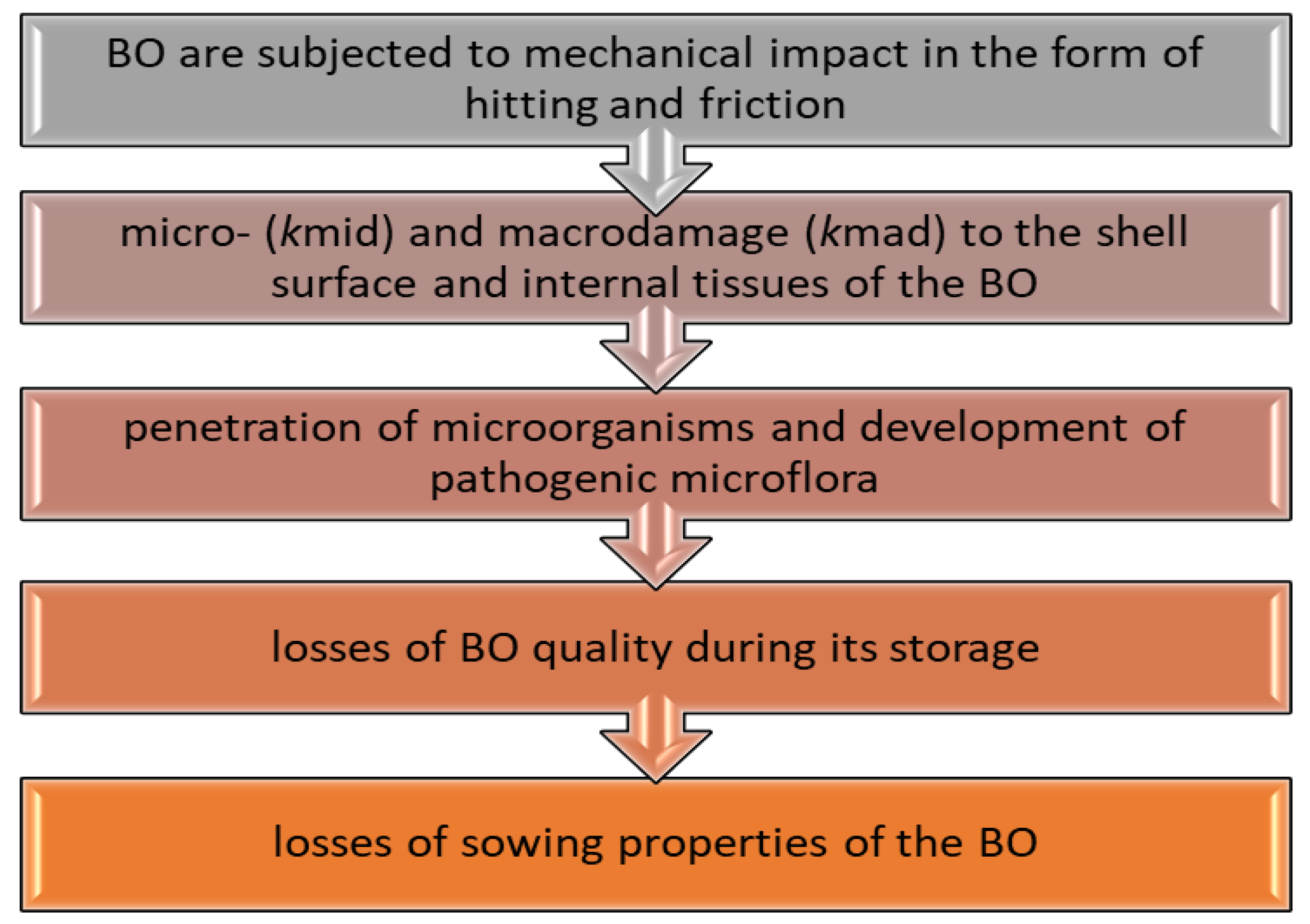
1. Introduction
2. Materials and Methods
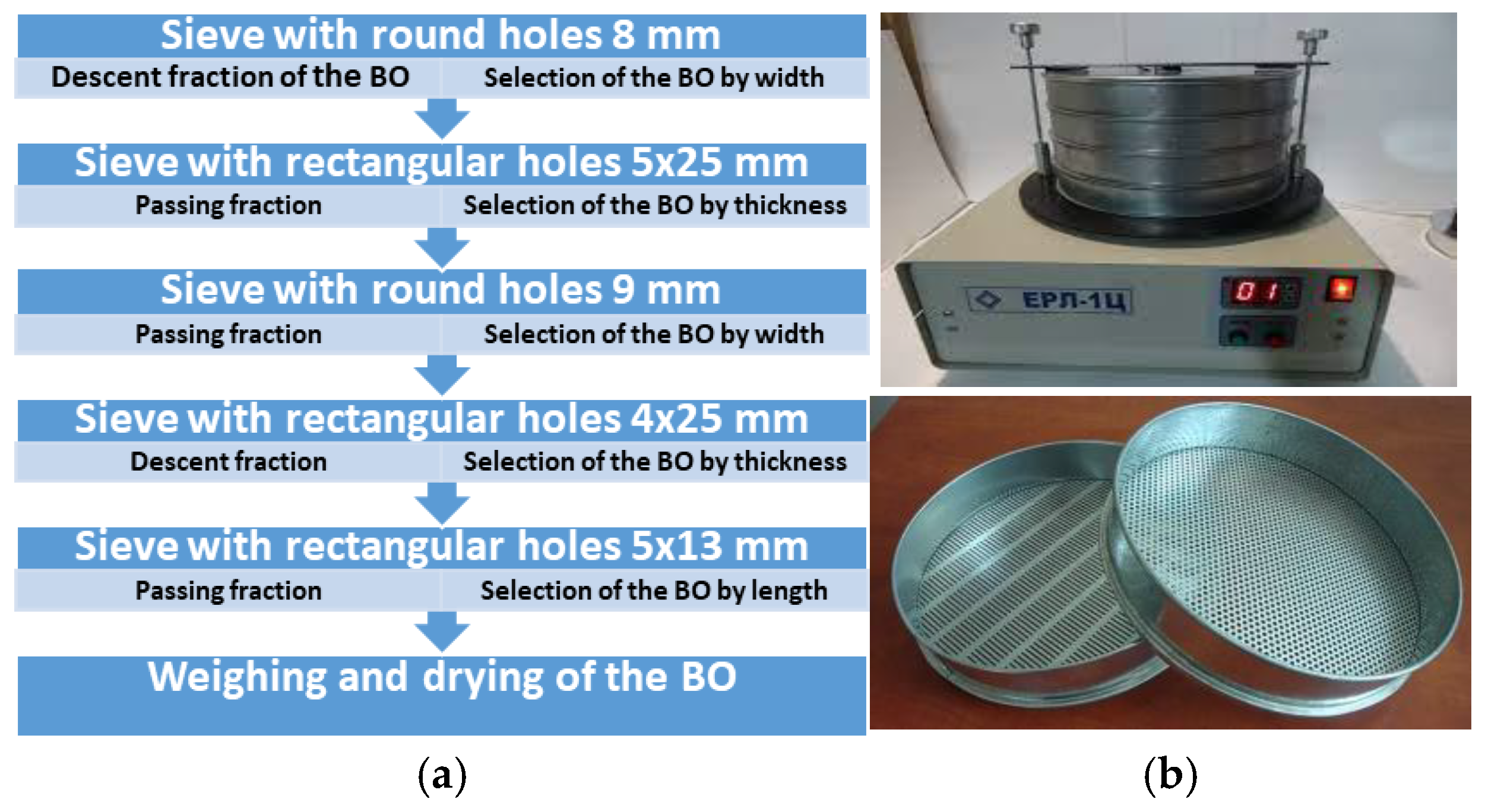
2.1. Sampling
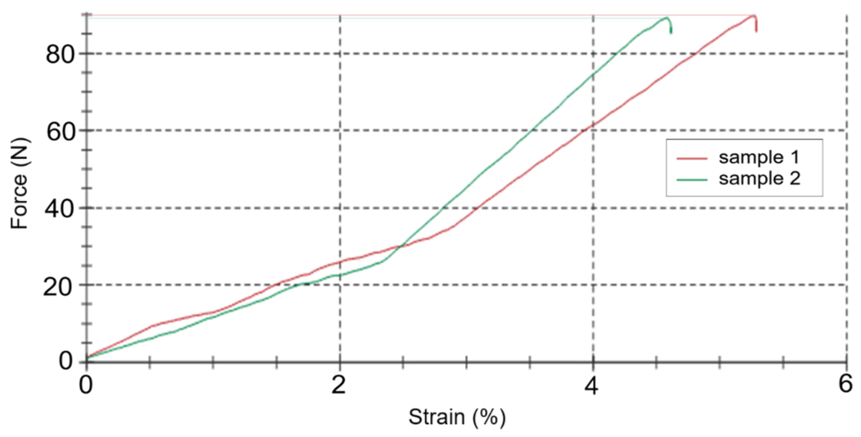
2.2. External Loading of the BO
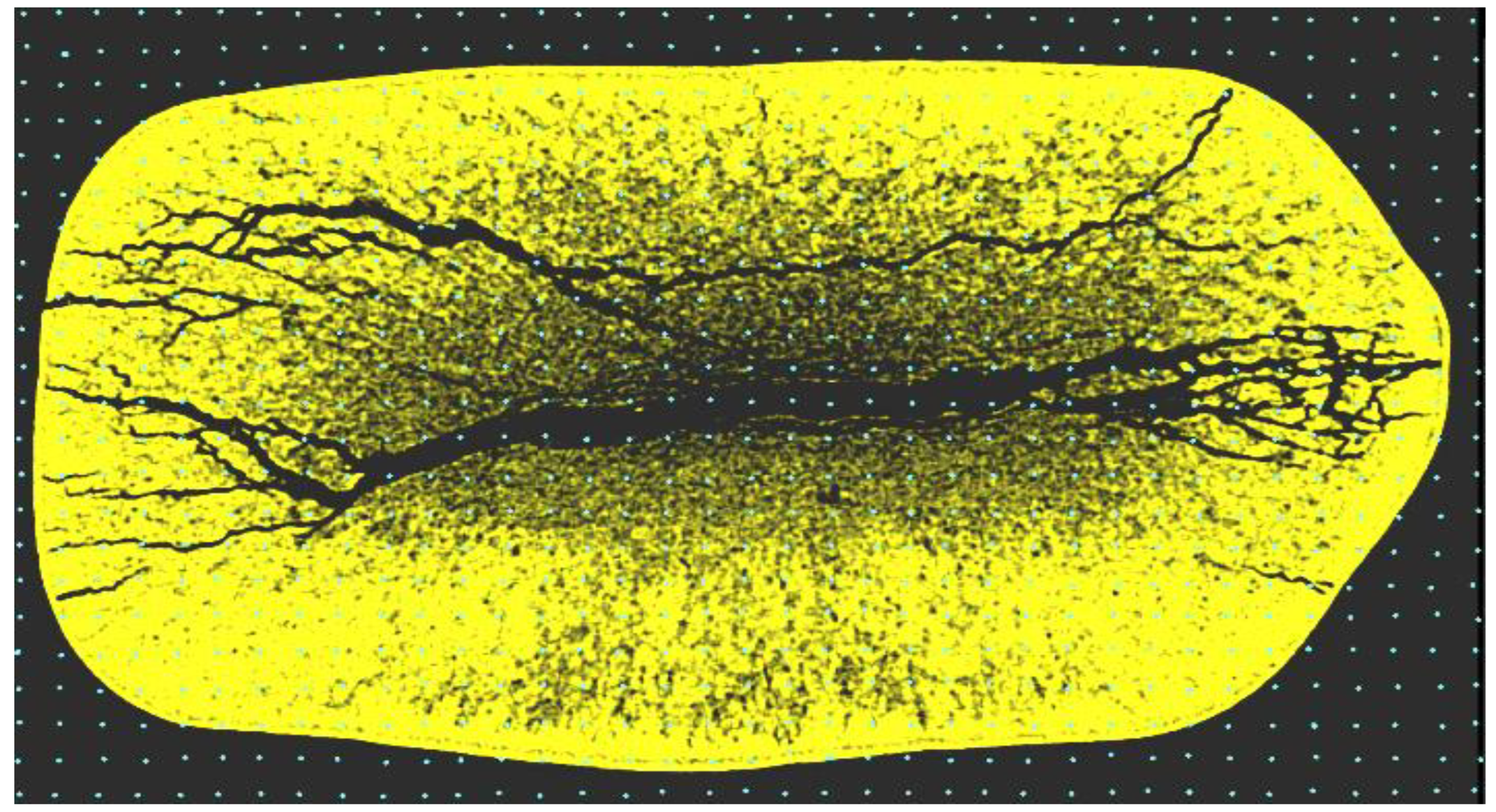
2.3. Tomography of Damaged BO
2.4. Data Processing Using the Monte Carlo Method
- Build a grid on the 2D image of the BO with a uniform distribution and generate the coordinates of the point (x, y).
- Check if the point (x, y) belongs to the shape (damage) that we are defining. If there is no hit, i.e., at least one of the system inequalities is not satisfied, then go to step 1 and generate the coordinates of the new point. If we have a hit, we fix it. The value of the hit counter increase the number of hits and go to point 1 again.
3. Results and Discussion
4. Conclusions
Author Contributions
Funding
Institutional Review Board Statement
Informed Consent Statement
Data Availability Statement
Acknowledgments
Conflicts of Interest
References
- Al Afif, R.; Bikić, S.; Radojčin, M. Bioenergy Conversion Technologies: A Review and Case Study. J. Process. Energy Agric. 2023, 27, 1450–5029. [Google Scholar] [CrossRef]
- Halkos, G.E. (Ed.) Current Issues in Natural Resource and Environmental Economics. In Economies; MDPI: Basel, Switzerland, 2023; p. 220. ISBN 978-3-0365-6260-5. [Google Scholar] [CrossRef]
- Kaletnik, G.M.; Palamarchuk, V.D.; Honcharuk, I.V.; Yemchyk, T.V.; Telekalo, N.V. Perspektyvy Vykorystannia Kukurudzy Dlia Enerhoefektyvnoho ta Ekolohobezpechnoho Rozvytku Silskykh Terytorii: Monohrafiia; FOP Kushnir Yu.V.: Vinnytsia, Ukraine, 2021; p. 260. [Google Scholar]
- Ng, H.F.; Wilcke, W.F.; Morey, R.V.; Meronuck, R.A.; Lang, J.P. Mechanical damage and corn storability. Trans. ASAE 1998, 41, 1095–1100. [Google Scholar] [CrossRef]
- Finch-Savage, W.E.; Bassel, G.W. Seed vigour and crop establishment: Extending performance beyond adaptation. J. Exp. Bot. 2016, 67, 567–591. [Google Scholar] [CrossRef] [PubMed]
- Khazaei, J.; Shahbazi, F.; Massah, J.; Nikravesh, M.; Kianmehr, M.H. Evaluation and Modeling of Physical and Physiological Damage to Wheat Seeds Under Successive Impact Loadings: Mathematical and Neural Networks Modeling. Crop Sci. 2008, 48, 1532–1544. [Google Scholar] [CrossRef]
- Derevyanko, D.A. Effect of Technical Means and Work Processes on Damaging and Quality of Seeds; Monograph: Zhitomir, Ukraine, 2015; p. 772. [Google Scholar]
- Frączek, J.; Kaczorowski, J.; Ślipek, Z.; Horabik, J.; Molenda, M. Standaryzacja metod pomiaru właściwości fizyczno-mechanicznych roślinnych materiałów ziarnistych. Acta Agrophysica 2003, 92, 1–169. [Google Scholar]
- Ślipek, Z.; Złobecki, A. Wpływ obciążeń wielokrotnych na uszkodzenia ziarna. Zesz. Probl. Postępu Nauk. Rol. 1992, 402, 197–203. [Google Scholar]
- Ślipek, Z.; Złobecki, A.; Frączek, J. Metoda oceny uszkadzalności ziarna przy uszkodzeniach wielokrotnych. Zesz. Probl. Postępu Nauk. Rol. 1994, 415, 187–195. [Google Scholar]
- Barbosa-Cánovas, G.V.; Juliano, P.; Peleg, M. Engineering Properties of Foods, in Food Engineering. In Encyclopedia of Life Support Systems (EOLSS); Barbosa-Cánovas, G.V., Ed.; Eolss Publishers: Oxford, UK, 2006; p. 31. [Google Scholar]
- Cicero, S.; Heijden, G.V.; Burg, W.V.; Bino, R.J. Evaluation of mechanical damage in seeds of maize (Zea mays L.) by X-ray and digital imaging. Seed Sci. Technol. 1998, 26, 603–612. [Google Scholar]
- Kęska, W. Badania przebiegu sił przy zderzeniu nasion niektórych roślin uprawowych z powierzchniami roboczymi maszyn rolniczych. Pr. Przemysłowego Inst. Masz. Rol. 1996, 41, 17–21. [Google Scholar]
- Michalak, D. Modelowe badania wytrzymałościowe ziarna zbóż na użytek projektowania maszyn rolniczych. Pr. PIMR 1997, 43, 17–21. [Google Scholar]
- Olshanskyi, V.; Kharchenko, S.; Kharchenko, F.; Kovalyshyn, S.; Shchur, T.; Gabriel, Y.; Bałdowska-Witos, P.; Tomporowski, A.; Kasner, R. About Calculation and Forecast of Temperature in the Layer Cell of Self-Heating of Raw Materials in a Silo. Sustainability 2022, 14, 14362. [Google Scholar] [CrossRef]
- Horabik, J.; Molenda, M. Właściwości fizyczne sypkich surowców spożywczych. Acta Agrophysica 2002, 74, 3–89. [Google Scholar]
- Horabik, J. Charakterystyka właściwości fizycznych roślinnych materiałów sypkich istotnych w procesach składowania. Acta Agrophysica 2001, 54, 5–121. [Google Scholar]
- Derevjanko, D.; Sukmaniuk, E.; Chychylyuk, S.; Grudovyi, R.; Derevjanko, O. The modeling of the seed injury dynamics. In Massachusetts Review of Science and Technologies; MIT Press: Cambridge, MA, USA, 2016; Volume 1, pp. 743–749. [Google Scholar]
- Piven, M.; Volokh, V.; Piven, A.; Kharchenko, S. Research into the process of loading the surface of a vibrosieve when a loose mixture is fed unevenly. East.-Eur. J. Enterp. Technol. 2018, 6, 62–70. [Google Scholar] [CrossRef]
- Akhmadiev, F.G.; Gizzyatov, R.F.; Kiyamov, K.G. Mathematical modeling of thin-layer separation of granular materials on sieve classifiers. Theor. Found. Chem. Eng. 2013, 47, 254–261. [Google Scholar] [CrossRef]
- Kharchenko, S.; Kovalishin, S.; Zavgorodniy, A.; Kharchenko, F.; Mikhaylov, Y. Effective sifting of flat seeds through sieve. INMATEH—Agric. Eng. 2019, 58, 17–26. [Google Scholar] [CrossRef]
- Zavgorodny, O.I. Scientific Bases of the Processes of Cleaning the Sieve Holes of Grain Cleaning Machines: Monograph; Osnova: Kharkiv, Ukraine, 2001; p. 163. [Google Scholar]
- Kharchenko, S.; Samborski, S.; Kharchenko, F.; Kotliarevskyi, I. Determination of Hole Blocking Conditions for Perforated Sifting Surfaces. Adv. Sci. Technol. Res. J. 2024, 18, 342–360. [Google Scholar] [CrossRef]
- Mohsenin, N.N. Physical Properties of Plant and Animal Materials: V. 1: Physical Characteristics and Mechanical Properties, 1st ed.; Routledge: New York, NY, USA, 1971. [Google Scholar] [CrossRef]
- Laskowski, J.; Janiak, G. Metodyka określania cech wytrzymałościowych ziarna dla potrzeb procesów przetwórczych. Biul. Nauk. Przemysłu Paszowego 1996, 1, 45–58. [Google Scholar]
- Łysiak, G. Wpływ Właściwości Fizycznych Surowców Roślinnych na Przebieg Procesu Rozdrabniania. Ph.D. Thesis, Akademia Rolnicza Lublin, Lublin, Poland, 1997. [Google Scholar]
- Woźniak, W.; Grundas, S.; Niewczas, J. Zastosowanie metody kolorymetrycznej i rentgenograficznej w badaniach uszkodzeń mechanicznych ziarna pszenicy. Ann. Univ. Mariae Curie-Skłodowska Sect. AAA Phys. 1992, 46–47, 469–475. [Google Scholar]
- Rahman, A.; Cho, B.-K. Assessment of seed quality using non-destructive measurement techniques: A review. Seed Sci. Res. 2016, 26, 285–305. [Google Scholar] [CrossRef]
- Hamdy, S.; Charrier, A.; Le Corre, L.; Rasti, P.; Rousseau, D. Toward robust and high-throughput detection of seed defects in X-ray images via deep learning. Plant Methods 2024, 20, 63. [Google Scholar] [CrossRef] [PubMed]
- Kovalyshyn, S.Y.; Shvets, O.P. Assessment of the degree of trauma to winter rapeseed by electron microscopic method. Bull. P.M. Vasylenko KHNTUA Tech. Sci. 2012, 1, 270–276. [Google Scholar]
- Niewczas, J. Ocena uszkodzeń mechanicznych ziarna pszenicy wykrywanych techniką rentgenograficzną. Acta Agrophysica 1994, 2, 1234–4125. [Google Scholar]
- Kytyr, D.; Koudelka, P.; Drozdenko, D.; Vavro, M.; Fíla, T.; Rada, V.; Vavro, L.; Mathis, K.; Soucek, K. Acoustic emission and 4D X-ray micro-tomography for monitoring crack propagation in rocks. Int. J. Rock Mech. Min. Sci. 2024, 183, 105917. [Google Scholar] [CrossRef]
- Piven, M.V. Substantiation of the Parameters of the Grating Separation Process of Grain Mixtures. Ph.D. Thesis, Kharkiv Petro Vasylenko KHNTUA, Kharkiv, Ukraine, 2006. [Google Scholar]
- Kawrakow, I.; Roges, D. The EGSnrc Code System: Monte Carlo Simulation of Electron Transport. In PIRS-701; NRCC: Ottawa, ON, Canada, 2000. [Google Scholar]
- Briesmeister, J.F. MCNP—A General Monte Carlo N-Particle Transport Code. Version 4B2; Los Alamos National Laboratory: Los Alamos, NM, USA, 1997; p. 736. [Google Scholar]
- Kling, A.; Baräo, F.J.C.; Nakagawa, M.; Távora, L.; Vaz, P. Advanced Monte Carlo for Radiation Physics, Particle Transport Simulation and Applications; Springer: Berlin/Heidelberg, Germany, 2001. [Google Scholar] [CrossRef]
- Available online: https://www.fao.org/faostat (accessed on 30 April 2025).
- Figiel, A. Właściwości mechaniczne ziarna polskiej pszenicy twardej. Inżynieria Rol. 2011, 134, 23–30. [Google Scholar]
- Dziki, D.; Laskowski, J. Wheat kernel physical properties and milling process. Acta Agrophysica 2005, 6, 59–71. [Google Scholar]
- Maize Biology: An Introduction, Directorate of Maize Research; Indian Council of Agricultural Research (ICAR): Technical Bullettin: New Delhi, India, 2012; Volume 2, p. 32.
- Fortes, M.; Okos, M.R. Changes in physical properties of corn during drying. Trans. ASAE 1980, 23, 1004–1009. [Google Scholar] [CrossRef]
- Księżak, J. Yield evaluation of maize varieties grown for grain in the organic and integrated system. Pol. J. Agron. 2021, 45, 12–20. [Google Scholar] [CrossRef]
- Cox, W.J.; Cherney, J.H. Agronomic comparisons of conventional and organic maize during the transition to an organic cropping system. Agronomy 2018, 8, 113. [Google Scholar] [CrossRef]
- Hossard, L.; Archer, D.W.; Bertrand, M.; Colnenne-David, C.; Debaeke, P.; Ernfors, M.; Jeuffroy, M.; Munier-Jolain, N.; Nilsson, C.; Sanford, G.R.; et al. Meta-analysis of maize and wheat yields in low-input vs. conventional and organic systems. Agron. J. 2016, 108, 1155–1167. [Google Scholar] [CrossRef]
- Kindruk, M.; Sliusarenko, O.; Hechu, V. Seeds of Agricultural Crops. Methods for Determining the Quality: DSTU 4138-2002 (State standard of Ukraine); Derzhspozhyvstandart Ukrainy: Kyiv, Ukraine, 2002; p. 173. [Google Scholar]
- Milivojević, M.; Ripka, Z.; Petrović, T. ISTA rules changes in seed germination testing at the beginning of the 21st century. J. Process. Energy Agric. 2018, 22, 40–45. [Google Scholar] [CrossRef]
- Rodrigues, D.M.; Coradi, P.C.; Teodoro, L.P.R.; Teodoro, P.E.; Moraes, R.d.S.; Leal, M.M. Monitoring and predicting corn grain quality on the transport and post-harvest operations in storage units using sensors and machine learning models. Sci. Rep. 2024, 14, 6232. [Google Scholar] [CrossRef] [PubMed]
- Kharchenko, S.; Samborski, S.; Kharchenko, F.; Korzec-Strzałka, I. The methodology and results of determining the geometric dimensions of loose material particles. In Proceedings of the IX International Conference of Computational Methods in Engineering Science—CMES 2024, Sandomierz, Poland, 27–29 November 2024; Book of Abstracts. p. 113. [Google Scholar]
- Wozniak, W.; Grundas, S. Porównanie właściwości mechanicznych ziarna pszenicy i jęczmienia przed oraz po nawilżaniu i suszeniu. Motrol Motoryz. Energetyka Rol. 2006, 08, 261–269. [Google Scholar]
- Horabik, J.; Beczek, M.; Mazur, R.; Parafiniuk, P.; Ryżak, M.; Molenda, M. Determination of the restitution coefficient of seeds and coefficients of visco-elastic Hertz contact models for DEM simulations. Biosyst. Eng. 2017, 161, 106–119. [Google Scholar] [CrossRef]
- Szwed, G.; Pecen, J. Wyniki badań współczynnika restytucji niektórych nasion roślin uprawnych. Inżynieria Rol. 2006, 4, 289–295. [Google Scholar]
- Wang, W.; Hua, X.; Wang, X.; Chen, Z.; Song, G. Advanced Impact Force Model for Low-Speed Pounding between Viscoelastic Materials and Steel. J. Eng. Mech. 2017, 143, 04017139. [Google Scholar] [CrossRef]
- Fraczek, J. A Test stand for fatigue testing of plant materials. Zesz. Probl. Postawowych Nauk. Rol. 1995, 426, 53–63. [Google Scholar]
- Fraczek, J.; Ślipek, Z. Influence of moisture content and number of mechanical impacts, upon the energy and sprouting capacity of wheat grains. Int. Agrophysics 1998, 12, 97–101. [Google Scholar]
- Kęska, W.; Marcinkiewicz, J.; Gierz, Ł.; Staszak, Ż.; Selech, J.; Koszela, K. Simulation Verification of the Contact Parameter Influence on the Forces’ Course of Cereal Grain Impact against a Stiff Surface. Appl. Sci. 2021, 11, 466. [Google Scholar] [CrossRef]
- Szwajka, K.; Szewczyk, M.; Trzepieciński, T. Experimental Compaction of a High-Silica Sand in Quasi-Static Conditions. Materials 2023, 16, 28. [Google Scholar] [CrossRef]
- Putri, R.E.; Yahya, A.; Adam, N.M.; Aziz, S.A. Related Fracture Resistance with Moisture Content in Different Grain Orientation of Paddy Grain. J. Biol. Agric. Healthc. 2015, 5, 64–69. [Google Scholar]
- Available online: https://info.dragonfly-pro.com/home.html (accessed on 30 April 2025).
- Rubinstein, R.Y.; Kroese, D.P. Simulation and the Monte Carlo Method, 3rd ed.; Wiley: Hoboken, NJ, USA, 2016; p. 345. [Google Scholar]
- Fischer, D.G.; Prahl, S.A.; Duncan, D.D. Monte Carlo modeling of spatial coherence: Free-space diffraction. J. Opt. Soc. Am. A 2008, 25, 2571–2581. [Google Scholar] [CrossRef] [PubMed]
- Doronin, A.; Malinski, I. Peer-to-peer Monte Carlo simulation of photon migration in topical applications of biomedical optics. J. Biomed. Opt. 2013, 17, 090504-1–090504-3. [Google Scholar] [CrossRef] [PubMed]
- Bajus, P.; Mraz, M.; Rigo, I.; Findura, P.; Fürstenzeller, A.; Kiełbasa, P.; Malaga-Toboła, U. The Influence of Drying Temperature and Moisture of Corn Seeds Planted on Their Damage. Agric. Eng. 2019, 23, 5–12. [Google Scholar] [CrossRef]
- Baryeh, E.A. A simple grain impact damage assessment device for developing countries. J. Food Eng. 2002, 56, 37–42. [Google Scholar] [CrossRef]
- Ptasznik, W.; Barnard, J.; Giec, W.; Khan, A.A. Susceptibility of bean seeds to thermal and impact damage. J. Agric. Eng. Res. 1995, 61, 137–144. [Google Scholar] [CrossRef]
- Shahbazi, F. Impact damage to chickpea seeds as affected by moisture content and impact velocity. Appl. Eng. Agric. 2011, 27, 771–775. [Google Scholar] [CrossRef]


| Technical Specifications | Value |
|---|---|
| Test load maximum, kN | 2.5 |
| Drive travel resolution, μm | 0.0277 |
| Initial force, N | 1 |
| Speed of measurement, mm/min | 5 |
| Paratemer | Value |
|---|---|
| X-ray source | 30–160 kV, 10 W maximum power, 12 filters for energy selection |
| X-ray detector | Dual-stage detector system with 2k × 2k pixel. The detector turret of multiple objectives (0.4×, 4×, 20×) at different magnifications with optimized scintillators for highest contrast |
| Spatial resolution | <0.7 µm true spatial resolution and below 70 nm voxel size |
| Reconstruction | XMReconstructor |
| Analysis software | Dragonfly Pro [58] |
| Radiation safety | <1 µSv/h at 10 cm from the instrument surface |
| Properties | Unit of Measurement | Value | |
|---|---|---|---|
| Min | Max | ||
| Density | kg/m3 | 618.13 | 622.35 |
| Length | mm | 12.09 | 13.11 |
| Width | mm | 8.02 | 9.07 |
| Thickness | mm | 4.1 | 5.05 |
| Moisture content | % | 14.92 | 15.11 |
Disclaimer/Publisher’s Note: The statements, opinions and data contained in all publications are solely those of the individual author(s) and contributor(s) and not of MDPI and/or the editor(s). MDPI and/or the editor(s) disclaim responsibility for any injury to people or property resulting from any ideas, methods, instructions or products referred to in the content. |
© 2025 by the authors. Licensee MDPI, Basel, Switzerland. This article is an open access article distributed under the terms and conditions of the Creative Commons Attribution (CC BY) license (https://creativecommons.org/licenses/by/4.0/).
Share and Cite
Kharchenko, S.; Samborski, S.; Al Afif, R.; Kharchenko, F.; Kłonica, M.; Piven, M. Development of a Methodology for Assessing Mechanical Damage in Biological Objects: Impact Parameters and Micro-Damage Analysis. Materials 2025, 18, 2075. https://doi.org/10.3390/ma18092075
Kharchenko S, Samborski S, Al Afif R, Kharchenko F, Kłonica M, Piven M. Development of a Methodology for Assessing Mechanical Damage in Biological Objects: Impact Parameters and Micro-Damage Analysis. Materials. 2025; 18(9):2075. https://doi.org/10.3390/ma18092075
Chicago/Turabian StyleKharchenko, Serhii, Sylwester Samborski, Rafat Al Afif, Farida Kharchenko, Mariusz Kłonica, and Mykhailo Piven. 2025. "Development of a Methodology for Assessing Mechanical Damage in Biological Objects: Impact Parameters and Micro-Damage Analysis" Materials 18, no. 9: 2075. https://doi.org/10.3390/ma18092075
APA StyleKharchenko, S., Samborski, S., Al Afif, R., Kharchenko, F., Kłonica, M., & Piven, M. (2025). Development of a Methodology for Assessing Mechanical Damage in Biological Objects: Impact Parameters and Micro-Damage Analysis. Materials, 18(9), 2075. https://doi.org/10.3390/ma18092075