
Mechanical Properties of Aluminum Alloy Tubes Fabricated Through Surface Mechanical Grinding Treatment and Graphene Lubrication Under Biaxial Stress States


Abstract
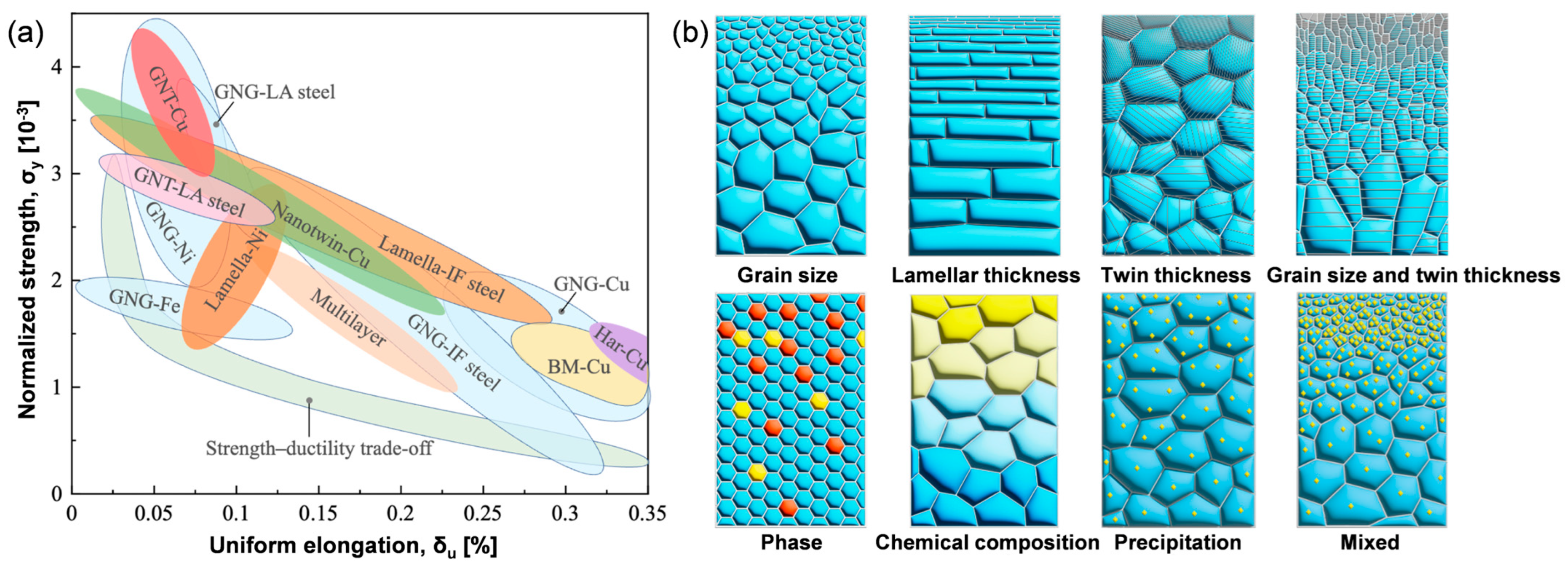
1. Introduction
2. Materials and Methods
2.1. Surface Mechanical Grinding Treatment for Tubes
2.2. Mechanical Property Testing of Tubes
2.3. Microstructure Characterization
3. Results
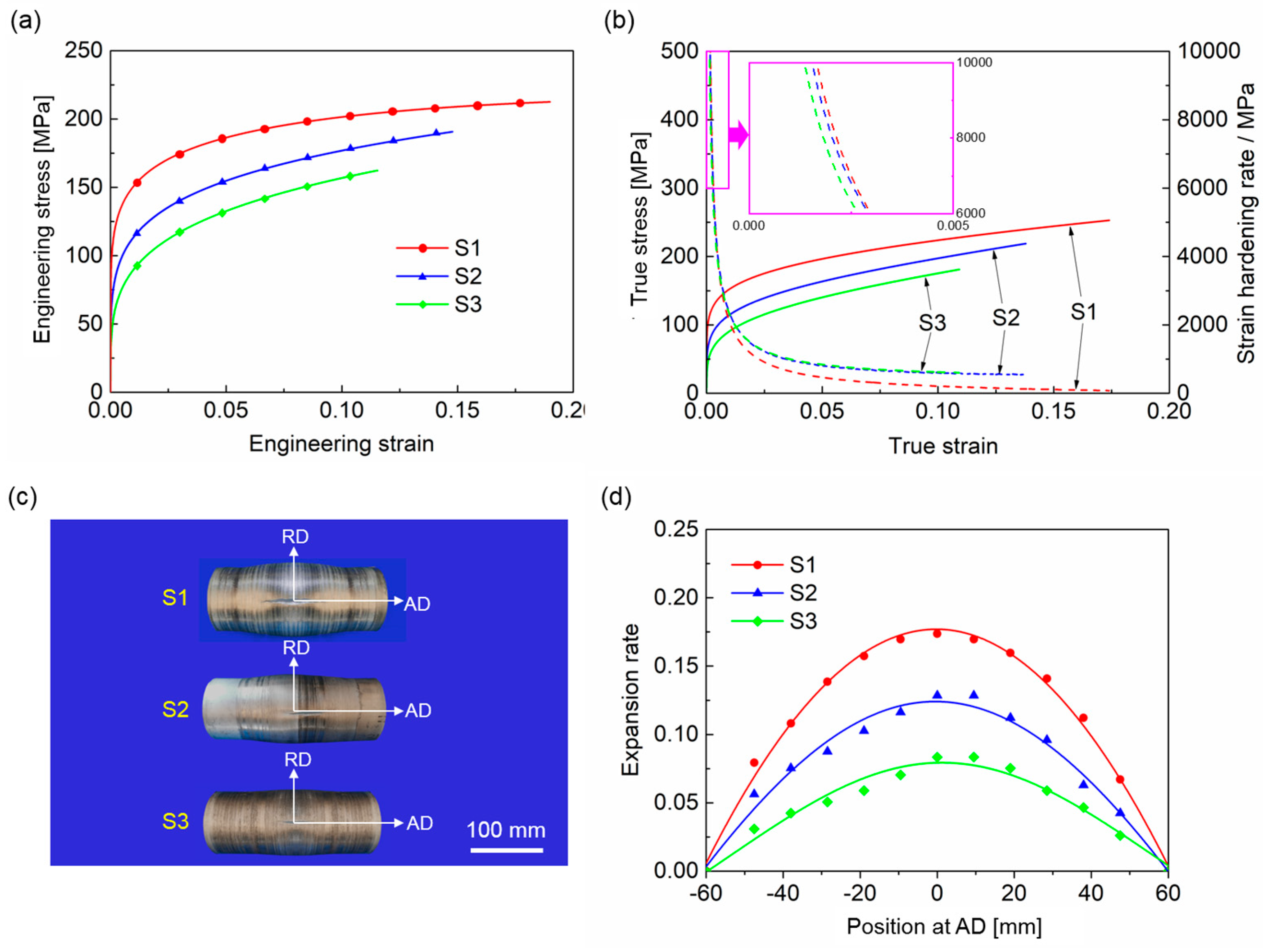
3.1. Mechanical Properties of Tubes Under Biaxial Stress States
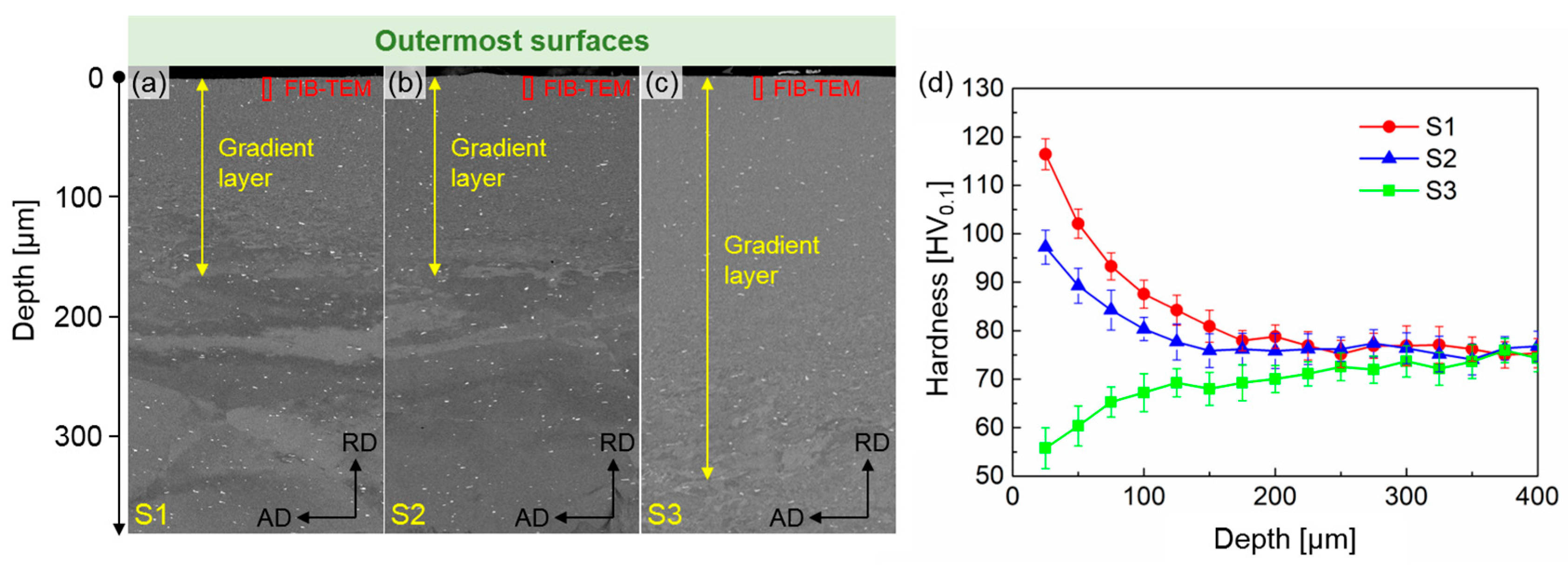
3.2. Microhardness Distributions at Cross-Sections
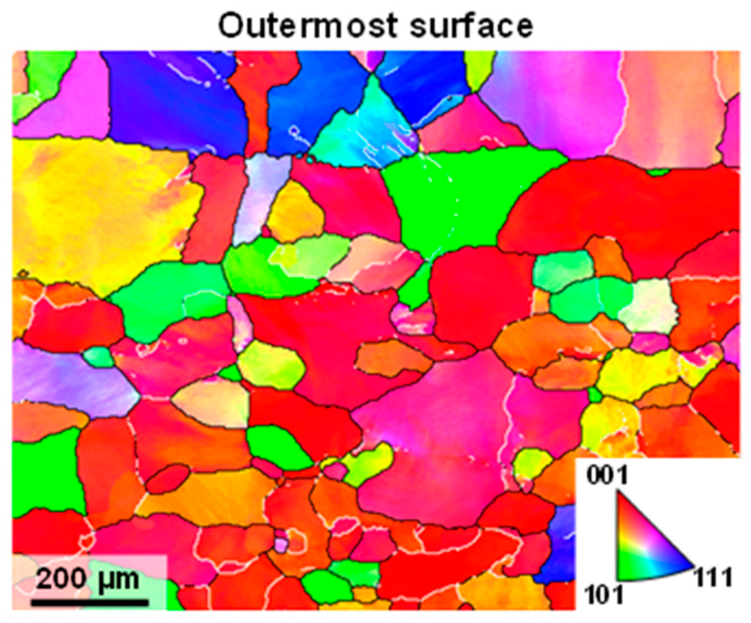
3.3. Microstructures at the Outermost Surface
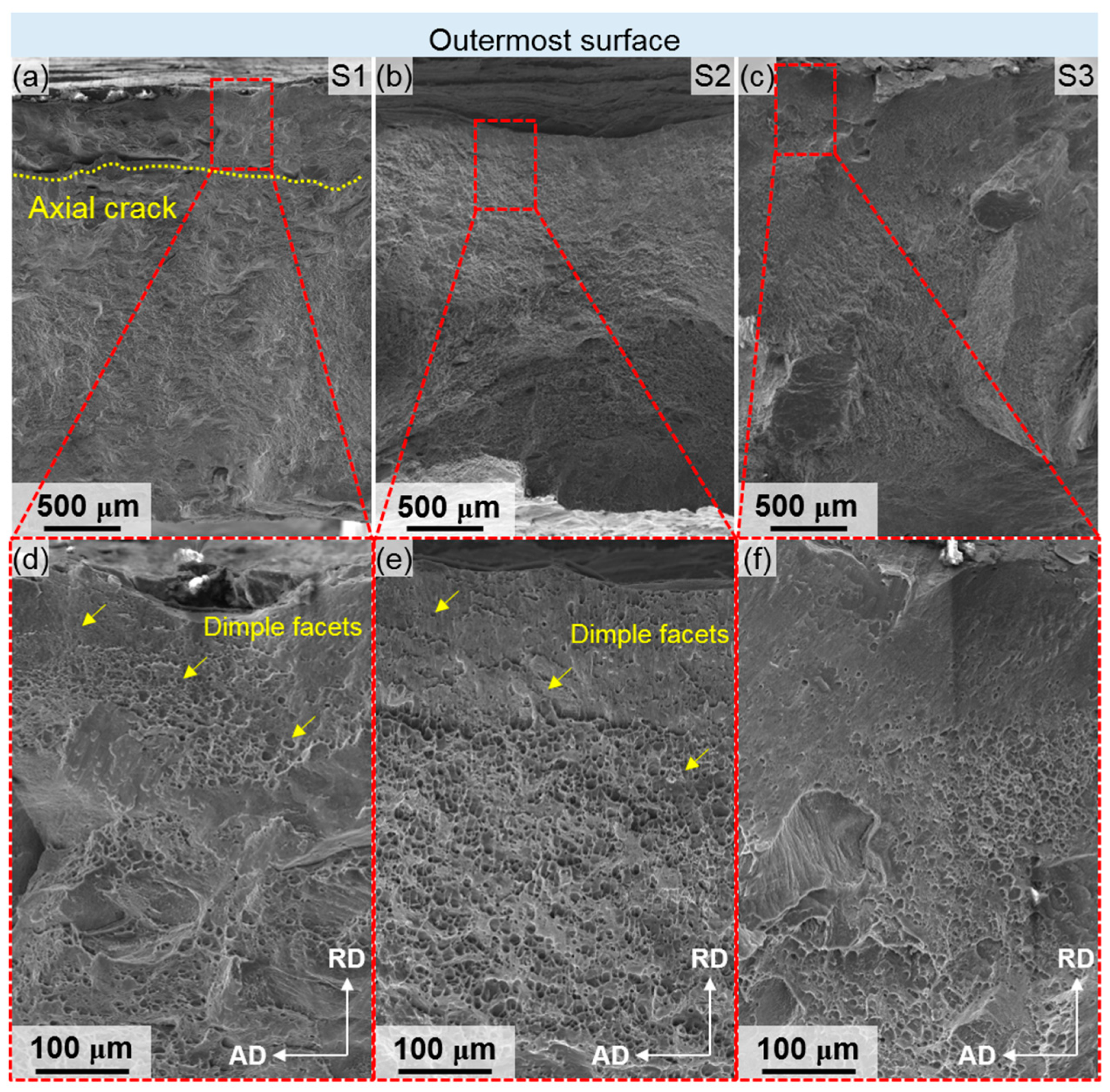
3.4. Fracture Morphologies of Bulged Tubes
4. Discussion
4.1. Microstructure of SMGTed Aluminum Alloy Tubes
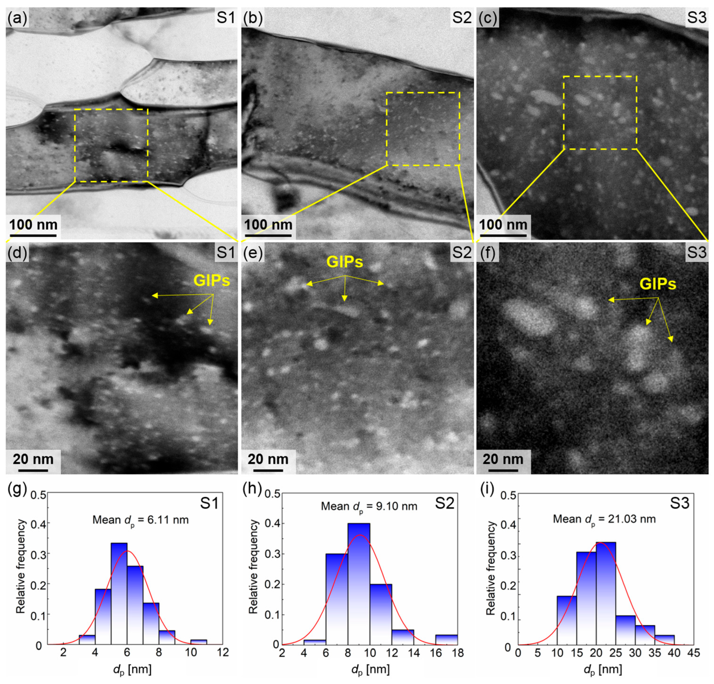
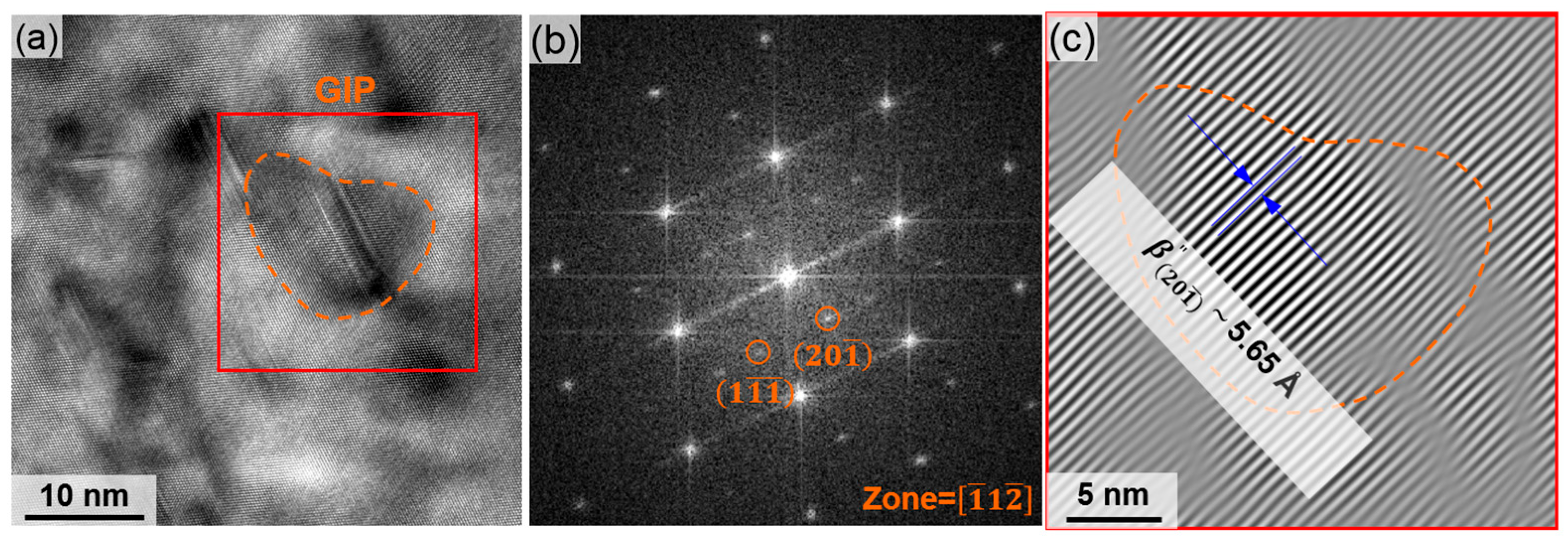
4.2. Precipitate Behavior in SMGTed Aluminum Alloy Tubes
4.3. Strengthening Mechanisms at the Outermost Surface of SMGTed Tubes
4.4. Deformation Mechanism of SMGTed Tubes During Hydro-Bulging
5. Conclusions
- Under graphene lubrication, surface mechanical grinding treatment (SMGT) was applied to the tubes. With water cooling, a gradient layer approximately 180 μm thick was formed, featuring an amorphous outer surface and nano-lamellar grains, along with internal (Mg5Si6) precipitates. The density of nano-precipitates increases with higher rotational speeds. In contrast, under air cooling conditions, the gradient layer exceeds 300 μm in thickness, displaying lamellar grains on the outer surface and containing both precipitates and oxides within its interior;
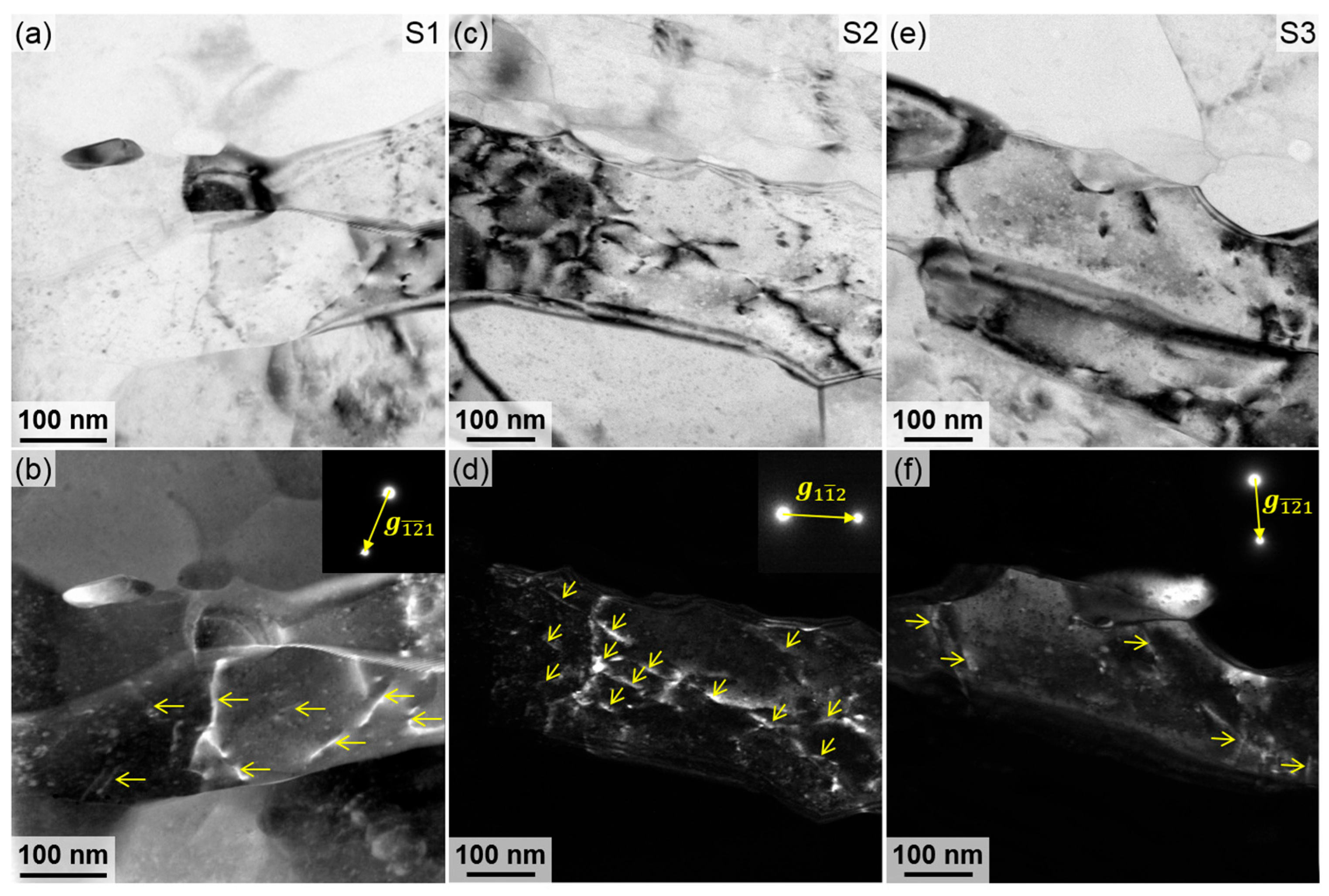
- The tube prepared under the condition of 1120 r/min with water cooling exhibits significantly enhanced strength during tube bulging, which can be attributed to grain boundary strengthening, precipitation strengthening, and dislocation hardening. Specifically, the yield strength reaches up to 120 MPa. In contrast, when the rotational speed is reduced to 710 r/min, the lamellar spacing decreases, the size of precipitates increases, and their density decreases. Despite this, the dislocation density increases, ultimately leading to a reduction in overall strength. Moreover, when the tube is fabricated at 1120 r/min with air cooling, oxides form within the lamellar grains, thereby compromising the mechanical strength;
- The tube, operating at a rotational speed of 1120 r/min under water-cooling conditions, demonstrates a high hardening rate during the initial deformation stage. Although this hardening rate decreases rapidly in subsequent stages, the tube retains a sustained strain hardening capability throughout the entire process. Fracture morphology analysis reveals that the gradient layer plays a critical role in enhancing the tube’s resistance to fracture across its entirety. In contrast, when the rotational speed is reduced to 710 r/min or air cooling is used instead of water cooling, both the sustained strain hardening capacity and ductility of the tubes decline significantly;
- Surface mechanical grinding treatment can effectively enhance the strength and toughness of aluminum alloy tubes at room temperature. The process parameters of this treatment are directly correlated with the gradient of microstructure and the resulting mechanical properties of the tube. Future research could leverage artificial intelligence to optimize these parameters, thereby fully maximizing the advantages of gradient-structured aluminum alloy tubes.
Supplementary Materials
Author Contributions
Funding
Institutional Review Board Statement
Informed Consent Statement
Data Availability Statement
Conflicts of Interest
Abbreviations
| SMGT | Surface Mechanical Grinding Treatment |
| AD | Axial Direction |
| RD | Radial Direction |
| GD | Grinding Direction |
| BSE | Backscattered Electron |
| FIB | Focused Ion Beam |
| TEM | Transmission Electron Microscopy |
| WBDF | Weak-Beam Dark-Field |
| SEM | Scanning Electron Microscopy |
| S1 | The First Set |
| S2 | The Second Set |
| S3 | The Third Set |
| HRTEM | High-Resolution Transmission Electron Microscopy |
| FFT | fast Fourier transform |
| GIP | Grain Internal Precipitation |
| HAADF | High Angle Annular Dark Field |
| EDS | Energy Dispersive Spectrometer |
| ω | Rotation speed |
| Horizontal length | |
| Vertical length | |
| Intersections of horizontal lines | |
| Intersections of vertical lines | |
| Thickness | |
| Dislocation density | |
| True strain | |
| True stress | |
| k | Hall–Petch coefficient |
| Strength increment due to grain refinement | |
| Strength increment due to precipitation | |
| Strength increment due to dislocation hardening | |
| Lamellar spacing | |
| Taylor factor | |
| Burgers vector | |
| Poisson’s ratio | |
| Shear modulus | |
| Average diameter of the nano-precipitations | |
| Average distance between neighboring the nano-precipitations |
References
- Yuan, S.; Fan, X. Developments and perspectives on the precision forming processes for ultra-large size integrated components. Int. J. Extreme Manuf. 2019, 1, 022002. [Google Scholar] [CrossRef]
- Cai, Y.; Wang, X.S.; Yuan, S.J. Pre-form design for hydro-forming of aluminum alloy automotive cross members. Int. J. Adv. Manuf. Technol. 2016, 86, 463–473. [Google Scholar] [CrossRef]
- Cai, Y.; Wang, X.; Yuan, S. Analysis of surface roughening behavior of 6063 aluminum alloy by tensile testing of a trapezoidal uniaxial specimen. Mater. Sci. Eng. A 2016, 672, 184–193. [Google Scholar] [CrossRef]
- Liu, X.C.; Zhang, H.W.; Lu, K. Formation of nano-laminated structure in nickel by means of surface mechanical grinding treatment. Acta Mater. 2015, 96, 24–36. [Google Scholar] [CrossRef]
- Li, X.; Lu, L.; Li, J.; Zhang, X.; Gao, H. Mechanical properties and deformation mechanisms of gradient nanostructured metals and alloys. Nat. Rev. Mater. 2020, 5, 706–723. [Google Scholar] [CrossRef]
- Nutor, R.K.; Cao, Q.; Wei, R.; Su, Q.M.; Du, G.H.; Wang, X.D.; Li, F.S.; Zhang, D.X.; Jiang, J.Z. A dual-phase alloy with ultrahigh strength-ductility synergy over a wide temperature range. Sci. Adv. 2021, 7, eabi4404. [Google Scholar] [CrossRef]
- Fang, T.H.; Li, W.L.; Tao, N.R.; Lu, K. Revealing Extraordinary Intrinsic Tensile Plasticity in Gradient Nano-Grained Copper. Science 2011, 331, 1587–1590. [Google Scholar] [CrossRef]
- Wang, J.J.; Tao, N.R.; Lu, K. Revealing the deformation mechanisms of nanograins in gradient nanostructured Cu and CuAl alloys under tension. Acta Mater. 2019, 180, 231–242. [Google Scholar] [CrossRef]
- Lu, K. Gradient Nanostructured Materials. Acta Metall. Sin. 2015, 51, 1–10. [Google Scholar]
- Ji, W.; Zhou, R.; Vivegananthan, P.; Wu, M.S.; Gao, H.; Zhou, K. Recent progress in gradient-structured metals and alloys. Prog. Mater. Sci. 2023, 140, 101194. [Google Scholar] [CrossRef]
- Xu, P.; Luo, H.; Han, Z.; Zou, J. Tailoring a gradient nanostructured age-hardened aluminum alloy using high-gradient strain and strain rate. Mater. Des. 2015, 85, 240–247. [Google Scholar] [CrossRef]
- He, Z.; Yuan, S.; Lin, Y.; Wang, X.X.; Hu, W.L. Analytical model for tube hydro-bulging tests, part II: Linear model for pole thickness and its application. Int. J. Mech. Sci. 2014, 87, 307–315. [Google Scholar] [CrossRef]
- He, Z.; Yuan, S.; Lin, Y.; Wang, X.X.; Hu, W.L. Analytical model for tube hydro-bulging test, part I: Models for stress components and bulging zone profile. Int. J. Mech. Sci. 2014, 87, 297–306. [Google Scholar] [CrossRef]
- Zhao, D.; Xie, K. Dislocation imaging via the virtual dark-field technique using the precession electron diffraction data. Microsc. Microanal. 2021, 27, 2916–2917. [Google Scholar] [CrossRef]
- Wang, S.; Hashimoto, N.; Wang, Y.; Ohnuki, S. Activation volume and density of mobile dislocations in hydrogen-charged iron. Acta Mater. 2013, 61, 4734–4742. [Google Scholar] [CrossRef]
- Zhu, Y.; Wu, X. Heterostructured materials. Prog. Mater. Sci. 2023, 131, 101019. [Google Scholar] [CrossRef]
- Wang, X.; Fan, X.; Chen, X.; Yuan, S. Cryogenic deformation behavior of 6061 aluminum alloy tube under biaxial tension condition. J. Mater. Process. Tech. 2022, 303, 117532. [Google Scholar] [CrossRef]
- He, Z.; Zhang, K.; Zhu, H.; Lin, Y.L.; Fu, M.; Yuan, S. An anisotropic constitutive model for forming of aluminum tubes under both biaxial tension and pure shear stress states. Int. J. Plast. 2022, 152, 103259. [Google Scholar] [CrossRef]
- Oh, J.; Park, H.D.; Gwak, M.; Lee, J.; Son, S.; Amanov, A.; Kim, H.; Seol, J.; Sunh, H.; Kim, J. Mechanical property enhancement in gradient structured aluminum alloy by ultrasonic nanocrystalline surface modification. Mater. Sci. Eng. A 2021, 812, 141101. [Google Scholar] [CrossRef]
- Hou, H.; Dong, R.; Tan, Y.; Li, C.; Zhang, X.; Wu, L.; Zhu, B.; Zhao, Y. Microstructural characteristics and enhanced mechanical properties of 2024 aluminum alloy resulting from shot-peening treatment. Mater. Charact. 2023, 206, 113412. [Google Scholar] [CrossRef]
- Meng, X.; Liu, B.; Luo, L.; Ding, Y.; Rao, X.; Hu, B.; Liu, Y.; Lu, J. The Portevin-Le Châtelier effect of gradient nanostructured 5182 aluminum alloy by surface mechanical attrition treatment. J. Mater. Sci. Technol. 2018, 34, 2307–2315. [Google Scholar] [CrossRef]
- Sahu, A.; Maurya, R.S.; Laha, T. Advances in Synthesis and Characterization of Aluminum-Based Amorphous Alloys: A Review. Adv. Eng. Mater. 2024, 26, 2301150. [Google Scholar] [CrossRef]
- Li, Y.; Hou, P.; Wu, Z.; Feng, Z.; Ren, Y.; Choo, H. Dynamic recrystallization of a wrought magnesium alloy: Grain size and texture maps and their application for mechanical behavior predictions. Mater. Des. 2021, 202, 109562. [Google Scholar] [CrossRef]
- Deng, S.Q.; Godfrey, A.; Liu, W.; Hansen, N. A gradient nanostructure generated in pure copper by platen friction sliding deformation. Scr. Mater. 2016, 117, 41–45. [Google Scholar] [CrossRef]
- Du, Y.; Huo, W.; Xu, J.; Zhang, W. Mechanical Behavior and Strengthening Mechanisms in Precipitation-Strengthened Aluminum Alloy with Gradient Structure Induced by Sliding Friction Treatment. Metall. Mater. Trans. A 2020, 51, 6207–6221. [Google Scholar] [CrossRef]
- Chrominski, W.; Lewandowska, M. Precipitation phenomena in ultrafine grained Al–Mg–Si alloy with heterogeneous microstructure. Acta Mater. 2016, 103, 547–557. [Google Scholar] [CrossRef]
- Kahlenberg, R.; Wojcik, T.; Falkinger, G.; Krejci, A.; Milkereit, B.; Kozeschnik, E. On the precipitation mechanisms of β-Mg2Si during continuous heating of AA6061. Acta Mater. 2023, 261, 119345. [Google Scholar] [CrossRef]
- Trink, B.; Weißensteiner, I.; Uggowitzer, P.J.; Strobel, K.; Hofer-Roblyek, A.; Pogatscher, S. Processing and microstructure–property relations of Al-Mg-Si-Fe crossover alloys. Acta Mater. 2023, 257, 119160. [Google Scholar] [CrossRef]
- Liao, Z.; Zhang, L.; Hou, X.; Huang, X. Grain boundary segregation of solutes and associated plastic deformation mechanisms in nanocrystalline Al–Cu and Al–Mg alloys: A molecular dynamics study. J. Mater. Res. Technol. 2025, 35, 25–36. [Google Scholar] [CrossRef]
- Ma, S.; Liu, W.; Li, Q.; Zhang, J.; Huang, S.; Xiong, Y.; Xu, B.; Yang, T.; Zhao, S. Mechanism of elemental segregation around extended defects in high-entropy alloys and its effect on mechanical properties. Acta Mater. 2024, 264, 119537. [Google Scholar] [CrossRef]
- Maleki, M.; Berndorf, S.; Mohammadzehi, S.; Mirzadeh, H.; Emamy, M.; Ullmann, M.; Prahl, U. Grain refinement and improved mechanical properties of Mg-4Zn-0.5Ca-0.5RE magnesium alloy by thermomechanical processing. J. Alloys Compd. 2023, 954, 170224. [Google Scholar] [CrossRef]
- Gu, Y.; Stiles, C.D.; El-Awady, J.A. A statistical perspective for predicting the strength of metals: Revisiting the Hall–Petch relationship using machine learning. Acta Mater. 2024, 266, 119631. [Google Scholar] [CrossRef]
- Ma, K.; Hu, T.; Yang, H.; Topping, T.; Yousefiani, A.; Lavernia, E.; Schoenung, J. Coupling of dislocations and precipitates: Impact on the mechanical behavior of ultrafine grained Al–Zn–Mg alloys. Acta Mater. 2016, 103, 153–164. [Google Scholar] [CrossRef]
- Mohammadi, A.; Enikeev, N.A.; Murashkin, M.Y.; Arita, M.; Edalati, K. Examination of inverse Hall-Petch relation in nanostructured aluminum alloys by ultra-severe plastic deformation. J. Mater. Sci. Technol. 2021, 91, 78–89. [Google Scholar] [CrossRef]
- Zhang, P.; Shi, K.; Bian, J.; Zhang, J.; Peng, Y.; Liu, G.; Deschamps, A.; Sun, J. Solute cluster evolution during deformation and high strain hardening capability in naturally aged Al–Zn–Mg alloy. Acta Mater. 2021, 207, 116682. [Google Scholar] [CrossRef]
- Hasan, M.; Liu, Y.; An, X.; Gu, J.; Song, M.; Cao, Y.; Li, Y.; Zhu, Y.; Liao, X. Simultaneously enhancing strength and ductility of a high-entropy alloy via gradient hierarchical microstructures. Int. J. Plast. 2019, 123, 178–195. [Google Scholar] [CrossRef]
- Li, G.; Liu, C.; Ma, P.; Yang, J.; Feng, Z. Improving formability and retaining dislocation hardening of heavily cold-worked Al alloy by fast heating and fast deformation. Mater. Sci. Eng. A 2021, 819, 141455. [Google Scholar] [CrossRef]
- Wu, X.; Zhu, Y.; Lu, K. Ductility and strain hardening in gradient and lamellar structured materials. Scr. Mater. 2020, 186, 321–325. [Google Scholar] [CrossRef]
- Zhang, J.; Zhang, X.; Wei, S.; Chen, X.; Pan, S.; Yang, C.; Pan, H.; Zhou, D.; Zhang, D.; Qin, G. Deformation faulting in ultrafine-grained aluminum alloys: Nucleation mechanisms and critical assessment of strengthening-ductilization contributions. Acta Mater. 2025, 286, 120750. [Google Scholar] [CrossRef]


| Mg | Cu | Si | Mn | Al |
|---|---|---|---|---|
| 0.60 | 0.10 | 0.40 | 0.10 | balanced |
| Specimen No. | Rotation Speed ω [r/min] | Lubrication | Cooling | Radial Feed | Grinding Tool Speed |
|---|---|---|---|---|---|
| S1 | 1120 | Grease/Graphene | Water-cooling | 0.5 mm | 5 mm/min |
| S2 | 710 | Water-cooling | |||
| S3 | 1120 | Air-cooling |
| Specimen No. | Yield Stress [MPa] | Ultimate Stress [MPa] | Ultimate Strain | Maximum Expansion Rate |
|---|---|---|---|---|
| S1 | 120 | 208 | 0.189 | 0.164 |
| S2 | 91 | 191 | 0.148 | 0.128 |
| S3 | 67 | 163 | 0.116 | 0.083 |
Disclaimer/Publisher’s Note: The statements, opinions and data contained in all publications are solely those of the individual author(s) and contributor(s) and not of MDPI and/or the editor(s). MDPI and/or the editor(s) disclaim responsibility for any injury to people or property resulting from any ideas, methods, instructions or products referred to in the content. |
© 2025 by the authors. Licensee MDPI, Basel, Switzerland. This article is an open access article distributed under the terms and conditions of the Creative Commons Attribution (CC BY) license (https://creativecommons.org/licenses/by/4.0/).
Share and Cite
Cai, Y.; Cui, X.-L.; Guo, C.; Jiang, F.; Yang, P. Mechanical Properties of Aluminum Alloy Tubes Fabricated Through Surface Mechanical Grinding Treatment and Graphene Lubrication Under Biaxial Stress States. Materials 2025, 18, 2038. https://doi.org/10.3390/ma18092038
Cai Y, Cui X-L, Guo C, Jiang F, Yang P. Mechanical Properties of Aluminum Alloy Tubes Fabricated Through Surface Mechanical Grinding Treatment and Graphene Lubrication Under Biaxial Stress States. Materials. 2025; 18(9):2038. https://doi.org/10.3390/ma18092038
Chicago/Turabian StyleCai, Yang, Xiao-Lei Cui, Chunhuan Guo, Fengchun Jiang, and Piaoping Yang. 2025. "Mechanical Properties of Aluminum Alloy Tubes Fabricated Through Surface Mechanical Grinding Treatment and Graphene Lubrication Under Biaxial Stress States" Materials 18, no. 9: 2038. https://doi.org/10.3390/ma18092038
APA StyleCai, Y., Cui, X.-L., Guo, C., Jiang, F., & Yang, P. (2025). Mechanical Properties of Aluminum Alloy Tubes Fabricated Through Surface Mechanical Grinding Treatment and Graphene Lubrication Under Biaxial Stress States. Materials, 18(9), 2038. https://doi.org/10.3390/ma18092038