Article

The Effect of Pulse Frequency on the Microstructure and Corrosion Resistance of an AZ31B Magnesium Alloy Composite Coating with Electron-Beam Remelting and Micro-Arc Oxidation

by
Yinghe Ma
1,2,
Zhen Yu
1,2,
Jinpeng Zhang
1,2,
Yonghui Hu
1,2,
Mengliang Zhou
1,2,
Jinhui Mei
1,2,
Zhihui Cai
3,*,
Wenjian Zheng
1,2 and
Jianguo Yang
1,2,*
1
Institute of Process Equipment and Control Engineering, College of Mechanical Engineering, Zhejiang University of Technology, Hangzhou 310023, China
2
Engineering Research Center of Process Equipment and Remanufacturing, Ministry of Education, Zhejiang University of Technology, Hangzhou 310023, China
3
Wenzhou Special Equipment Inspection & Science Research Institute, Wenzhou 325800, China
*
Authors to whom correspondence should be addressed.
Materials 2025, 18(9), 1962; https://doi.org/10.3390/ma18091962
Submission received: 24 February 2025 / Revised: 8 April 2025 / Accepted: 22 April 2025 / Published: 25 April 2025
(This article belongs to the Special Issue Latest Research in Joining and Welding Processes)

Abstract

:
This study presents a systematic investigation into the influence of pulse frequency on the micro-arc oxidation (MAO) coating of AZ31B magnesium alloy following electron-beam remelting (EBR). The morphology, thickness, and corrosion resistance of the EBR-MAO composite coating were meticulously analyzed across various pulse frequencies (100 Hz, 200 Hz, 300 Hz, 400 Hz) employing scanning electron microscopy (SEM), X-ray diffraction (XRD), and electrochemical measurement techniques. The results show that as the pulse frequency escalates from 100 Hz to 400 Hz, the average thickness of the EBR-MAO composite coating diminishes from 41.1 μm to 38.5 μm, reduced by 6.7% compared to 10.4% in the MAO coating. Concurrently, the porosity exhibits a reduction from 1.93% to 1.35%, accompanied by a densification of the coating’s structure. High pulse frequencies yield coatings with enhanced smoothness and fewer defects. Notably, the corrosion resistance of the coatings demonstrates significant improvement at higher frequencies (400 Hz) compared to their lower-frequency (100 Hz) counterparts, as evidenced by a tenfold increase in corrosion current density. This research underscores the pivotal role of pulse frequency in optimizing the protective qualities of MAO coatings on magnesium alloys.

1. Introduction

Magnesium alloys, as an important class of lightweight structural materials, possess advantages such as weight ratio, good ductility, excellent processability, and low density [1,2,3]. Additionally, the degradation of magnesium alloys in the human body releases magnesium ions with good biocompatibility, making them highly promising in various fields including engineering machinery, aerospace, biomedical applications, the automotive industry, sports equipment, and electronic devices. As such, magnesium alloys are regarded as one of the most promising metal materials of the 21st century [4,5,6].
However, due to their chemically active nature and the presence of secondary phases such as aluminum and manganese, magnesium alloys have a stable potential of −1.5 to −1.6 V in seawater, making them highly susceptible to surface oxidation and galvanic corrosion [7,8,9]. This results in poor corrosion resistance in various media, greatly limiting their practical applications in engineering. Therefore, to enhance corrosion resistance and extend service life, surface treatment is essential. Commonly used surface-treatment methods include electrochemical treatments, electroplating and electroless plating, organic coating treatments, and surface-modification technologies [10,11,12,13].
In terms of improving surface properties, W. Li et al. [14] significantly enhanced the wear and corrosion resistance of AZ31B magnesium alloy micro-arc oxidation (MAO) coatings through laser surface melting (LSM) pretreatment. After LSM treatment, the grain size of the substrate was significantly refined, the average pore area of the MAO coating decreased to 0.84 μm2, porosity was reduced to 7.14%, the wear rate decreased by 50%, the self-corrosion current density was reduced by two orders of magnitude, and polarization resistance increased by one order of magnitude. Y.J. Wang [15] further confirmed that the grain size and uniformity of magnesium alloys are key factors affecting their corrosion resistance. S.Y. Huang et al. [16] found that introducing an anodic pause time (as opposed to a cathodic pause) in the MAO process significantly improved the corrosion resistance of the coating. H.R. Dong et al. [17] systematically studied the coating-formation ability and performance of MAO coatings in different types of single electrolytes, offering deeper insight into the coating-formation mechanism. L.J. Bai et al. [18] employed an asymmetric bipolar pulse MAO technique to fabricate black, corrosion-resistant, and light-absorbing ceramic coatings on AZ31 magnesium alloy and investigated the influence of positive pulse voltage on coating color and corrosion resistance. D.Y. Wang et al. [19] aimed to regulate the degradation rate of AZ31B magnesium alloy for use in biomedical implants by creating microporous structures with varying pore diameters and spacings on the MAO coating surface using femtosecond lasers. H.K. Pan et al. [20] first applied MAO to AZ31 alloy and then conducted cathodic deposition (CD) in an ethylene glycol organic electrolyte, successfully preparing composite coatings with excellent corrosion and friction resistance. S. Sun et al. [21] sequentially applied laser remelting, MAO treatment, and layered double hydroxide (LDH) sealing treatment on AZ31 alloy, significantly enhancing the corrosion resistance of the composite coatings.
Although LSM is widely applied, it poses challenges when used on magnesium alloys due to their sensitivity to oxidation during laser processing, which may negatively affect subsequent MAO treatment. In contrast, electron-beam remelting (EBR) technology has recently attracted increasing attention. EBR has gained wide interest due to its unique advantages. Compared with other surface-modification techniques, EBR offers several notable advantages [22,23]: (1) high energy density and rapid heating with a small heat-affected zone, beneficial for preserving the substrate properties; (2) precise control over processing parameters; (3) rapid solidification conducive to grain refinement and property enhancement; and (4) operation in a vacuum environment, which avoids high-temperature oxidation and facilitates the formation of dense, high-quality modified layers. G.H. Zhao et al. [24] used EBR to improve the surface performance of stainless steel, achieving enhanced surface morphology, reduced roughness, refined grains, and increased dislocations density. J.Y. Yao et al. [25] applied EBR to improve the surface properties of Inconel 625 nickel-based alloy, and the modified material showed significant reductions in oxidative and adhesive wear compared to the untreated material.
At present, single surface-treatment methods can no longer meet the complex and demanding requirements of practical engineering applications. The fabrication of high-performance composite coatings by combining multiple surface-treatment techniques has gradually become a research hotspot and development trend in the field of surface engineering. Previous studies have shown that EBR significantly improves the density and corrosion resistance of MAO coatings on AZ31B magnesium alloy [26]. Given that electrical parameters in the MAO process—especially pulse frequency—have a major influence on the microstructure and properties of the coatings, further in-depth research is necessary to optimize these parameters and enhance the overall performance of the composite coatings.
In this study, AZ31B magnesium alloy samples treated with EBR were subjected to MAO treatment under different pulse-frequency conditions. The effects of pulse frequency on the microstructure and composition of the coatings were systematically analyzed, and the corrosion resistance of the resulting composite coatings was thoroughly evaluated. Based on the experimental results, the influence mechanism of pulse frequency on the performance of EBR-MAO composite coatings was elucidated, providing valuable theoretical guidance and technical insights for optimizing coating processes and improving the comprehensive performance of magnesium alloy materials.

2. Experimental Details

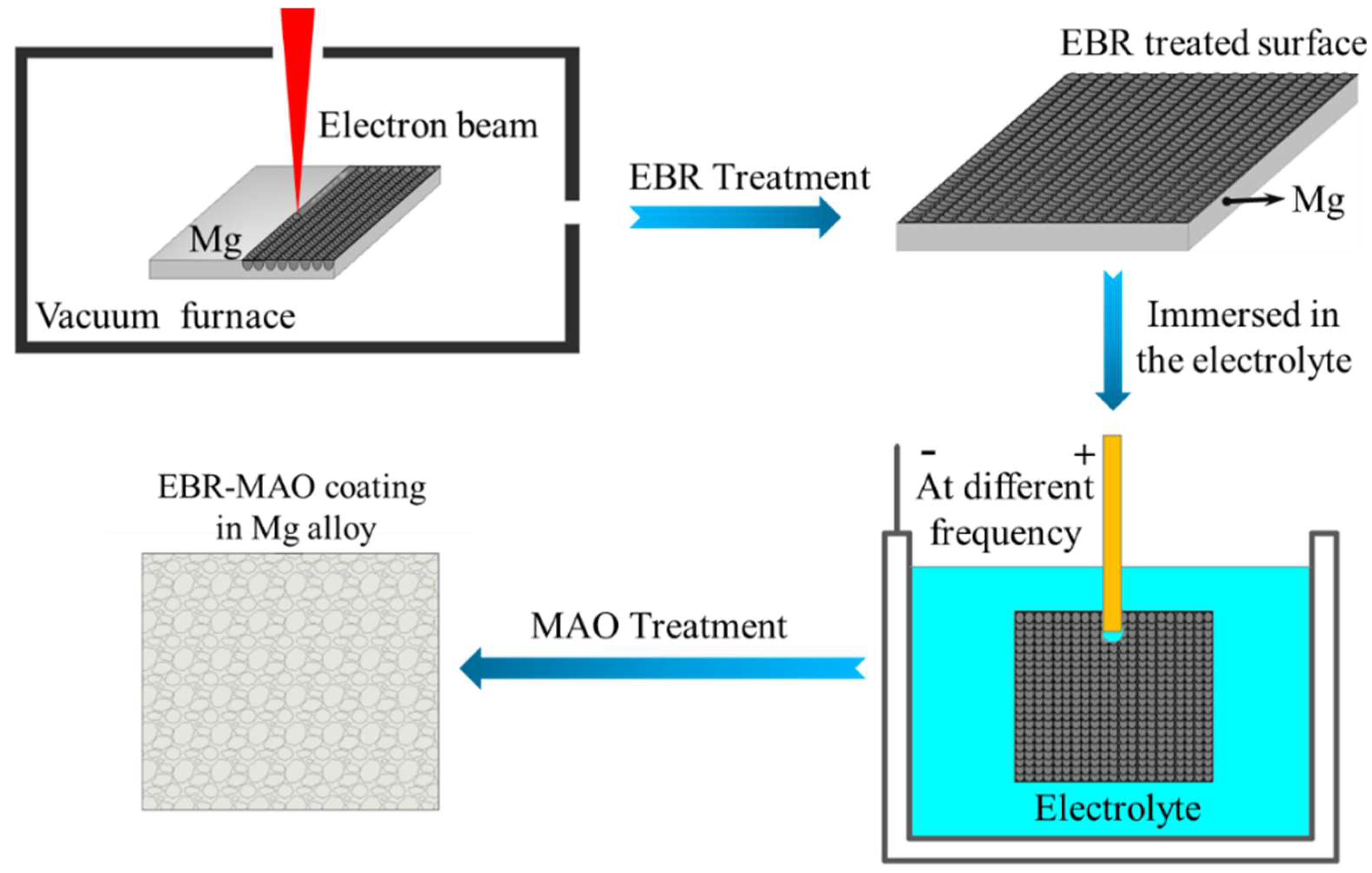
2.1. Preparation of EBR AZ31B Magnesium Alloy Samples

AZ31B magnesium alloy plates with a thickness of 2 mm were machined into specimens measuring 33 × 33 mm. The surfaces were sequentially ground using 320#, 600#, 800#, and 1000# SiC abrasive papers until smooth. The specimens were then ultrasonically cleaned in acetone and ethanol for 3 min each to thoroughly remove surface oils and other contaminants. Electron-beam remelting (EBR) was performed on the prepared AZ31B specimens using a THDW-4 electron-beam welding machine manufactured by Guilin Sida Technology Co., Ltd. (Guilin, China). The EBR process parameters were as follows: an accelerating voltage of 65 kV, a welding speed of 200 mm/min, a beam overlap rate of 50%, and an electron-beam current of 0.5 mA.

2.2. Preparation of EBR-MAO Composite Coatings

After the EBR process, the samples were further ground and polished using sandpapers and a 0.25 μm diamond suspension polishing agent to ensure a smooth surface. The samples were then ultrasonically cleaned in alcohol and acetone, followed by drying for subsequent use. The micro-arc oxidation (MAO) treatment was performed in a silicate-based electrolyte system (Na2-SiO3: 8 g/L, NaF: 0.5 g/L, KOH: 1 g/L, pH 12–13) with an electrolyte volume of 6 L. The MAO process was conducted under constant-voltage mode with the following parameters: a voltage of 520 V, a duty cycle of 20%, a treatment time of 20 min, and pulse frequencies of 100, 200, 300, and 400 Hz. The MAO sample numbers at different frequencies are as follows: M100, M200, M300, M400. The EBR-MAO sample numbers at different frequencies are as follows: EM100, EM200, EM300, EM400. During the MAO process, the electrolytic cell was cooled using circulating water to maintain the temperature below 40 °C. After the MAO treatment, the samples were rinsed with deionized water for 3 min to remove residual electrolytes. A schematic diagram illustrating the preparation process of the EBR-MAO composite coatings is presented in Figure 1.

2.3. Characterization

The surface roughness of the substrate with and without electron-beam remelting (EBR) treatment was characterized using an Olympus laser confocal microscope (OLS5000 model, Beijing, China). The microstructure of MAO (micro-arc oxidation) and EBR-MAO coatings at different pulse frequencies was observed using Hitachi ultra-high resolution scanning electron microscope (FE-SEM SUS8010, Guangzhou, China) and its accompanying Bruker D8 Advance energy dispersive spectrometer (EDS) (Shanghai, China). In addition, D8 Discoverer X-ray diffractometer (XRD) was used to analyze the phases of MAO and EBR-MAO coatings at different pulse frequencies.
The electrochemical performance test was conducted using the CorrTest CS350H electrochemical workstation (Wuhan, China), based on the classic three-electrode battery system: the sample was used as the working electrode (WE), the platinum plate was used as the auxiliary electrode (CE), and the saturated calomel electrode (RE) was used as the reference electrode. The electrochemical testing medium is a 3.5 wt.% NaCl solution. The testing includes alternating current impedance testing (EIS) and dynamic potential scanning testing. In AC impedance testing, the amplitude of the AC signal is 10 mV and the frequency range is 10−1~105 Hz. In the dynamic potential scanning test, the potential scanning range is −3.5~0.5 V, and the scanning speed is 1 mV/s, in order to obtain the polarization curve and further analyze the corrosion resistance of the coating.

3. Results and Discussion

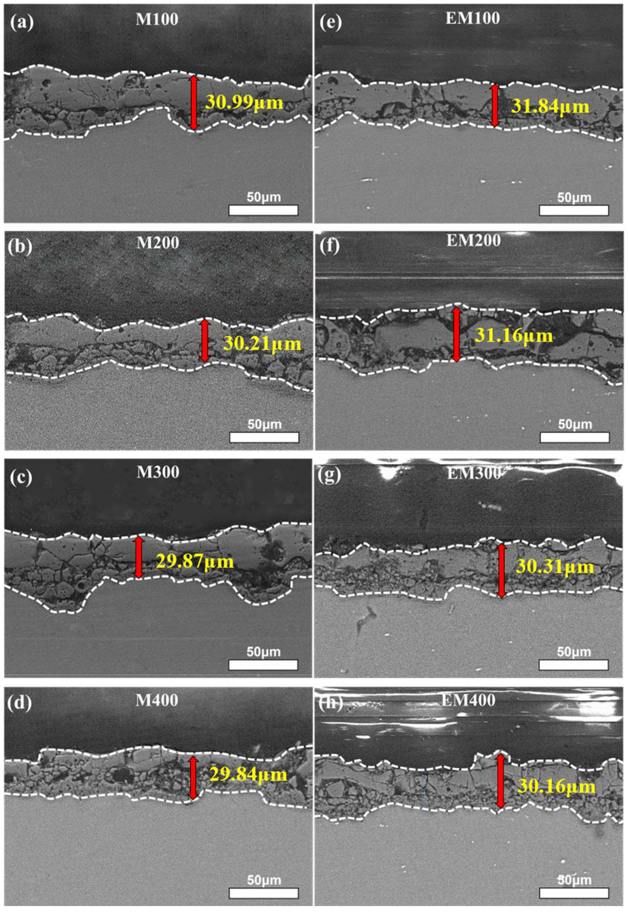
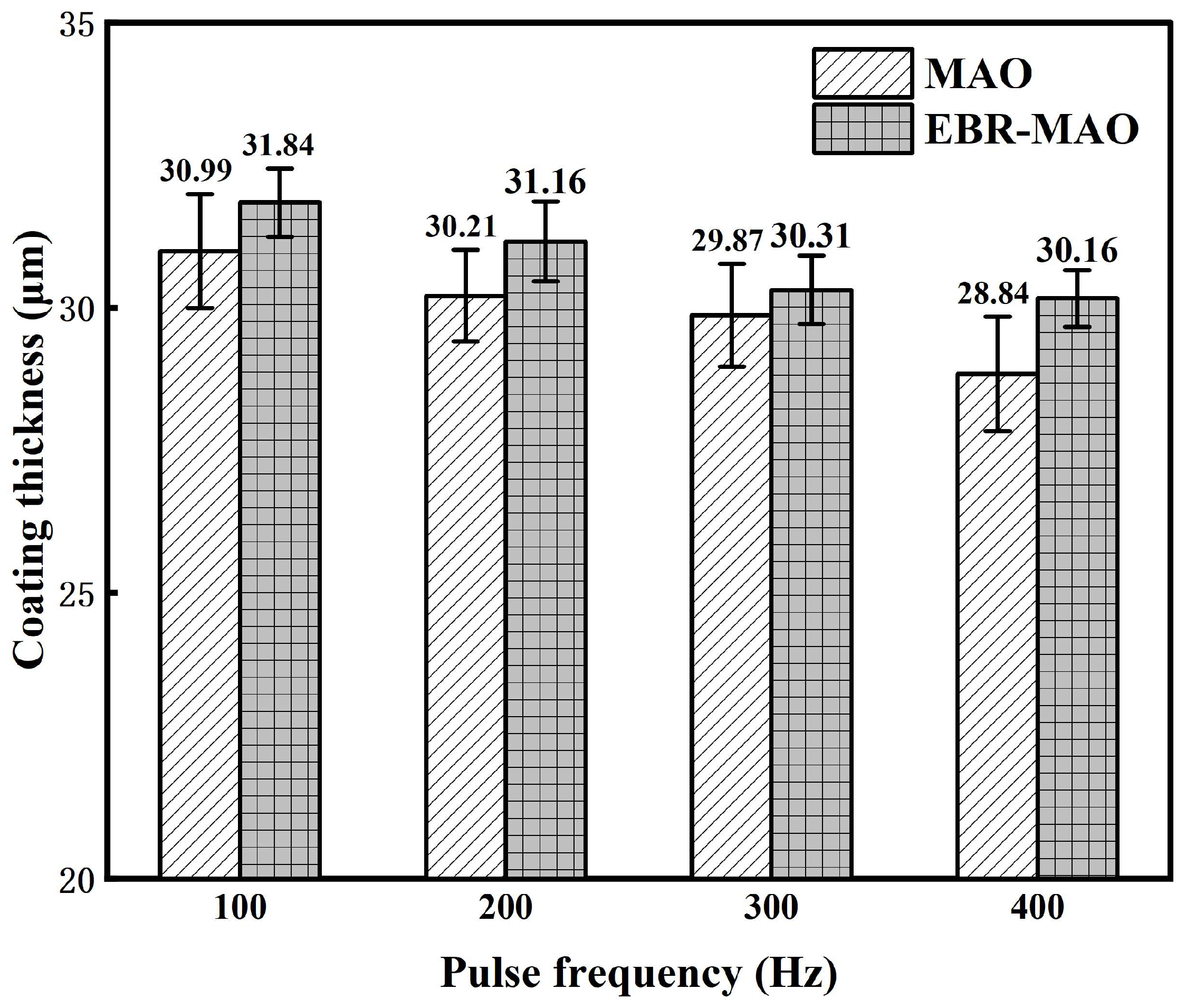
3.1. Cross-Sectional Morphology and Thickness of the Composite Coating

Figure 2 shows the 3D morphology of the substrate surface with and without electron-beam remelting. It can be seen from the figure that there is not much difference in the 3D contour between the two, but the roughness of the substrate has decreased from 2.785 μm to 2.155 μm, indicating that the surface roughness of the substrate has been reduced after electron-beam remelting.
Figure 3 presents the cross-sectional morphology of the MAO coatings and EBR-MAO coatings at different pulse frequencies. The bonding between coating and substrate is metallurgical bonding. The uneven interface observed in the MAO coating–substrate system can be attributed to the high temperature and pressure generated during the breakdown of the micro-arc oxidation film layer. This process causes localized melting of the film layer and substrate, resulting in an uneven metallurgical bond [27]. Notably, the interface between the EBR-MAO coating and the substrate is significantly smoother compared to that of the MAO coating and substrate. The EBR treatment refines the grains on the substrate surface and reduces the original surface roughness of the substrate. These modifications facilitate the formation of a denser layer, which subsequently influences the breakdown and discharge behavior during the MAO process, leading to a more uniform and compact coating structure.
Figure 4 illustrates the average thickness of MAO coatings and EBR-MAO coatings at different pulse frequencies. The trend in thickness variation for both MAO and EBR-MAO coatings is consistent across the pulse frequencies. As the pulse frequency increases, the thickness of the coatings gradually decreases. This phenomenon can be attributed to the reduction in pulse duration within each cycle at higher frequencies, which leads to fewer discharges occurring at the same location and weaker discharge intensity. Weaker discharges result in lower temperatures and pressures within the discharge channels, reducing the amount of oxide that is melted, sputtered, and deposited. Consequently, at higher pulse frequencies, the growth rate of the coating is slower [15,21]. This trend highlights the critical role of pulse frequency in controlling the thickness and growth dynamics of MAO and EBR-MAO coatings.

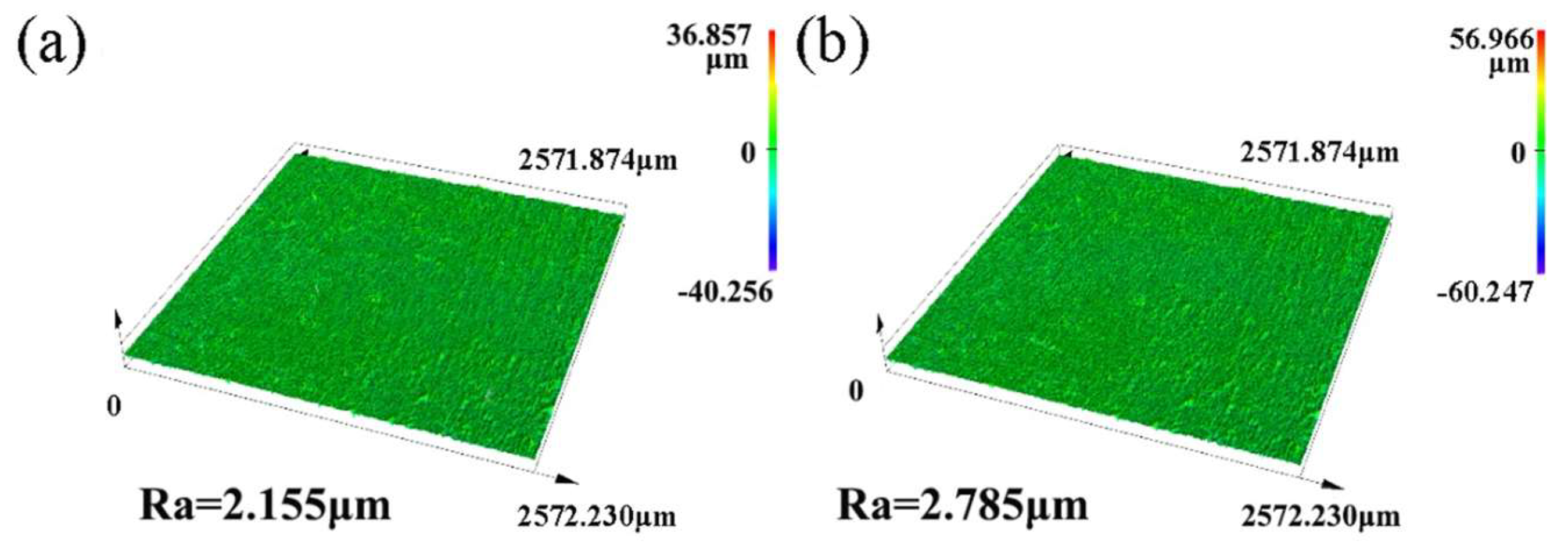
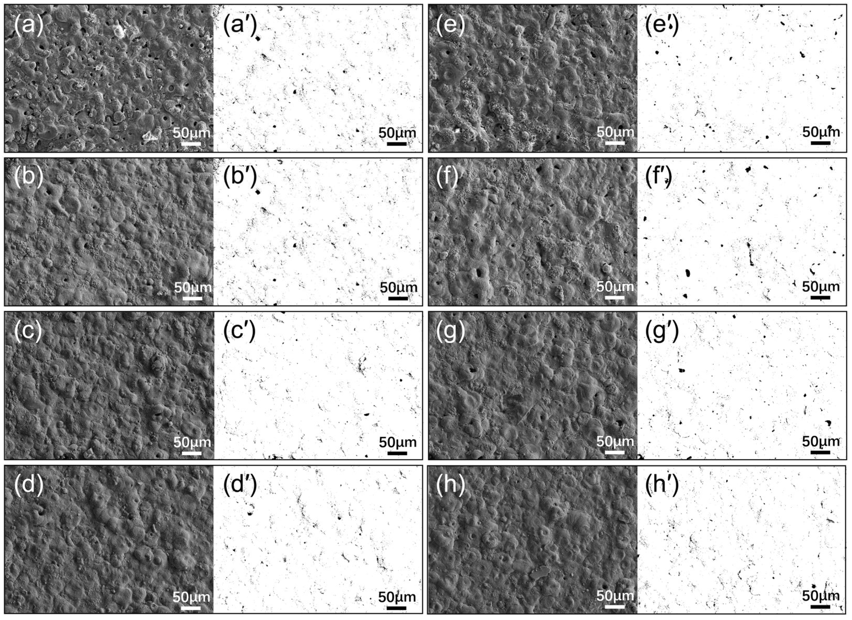
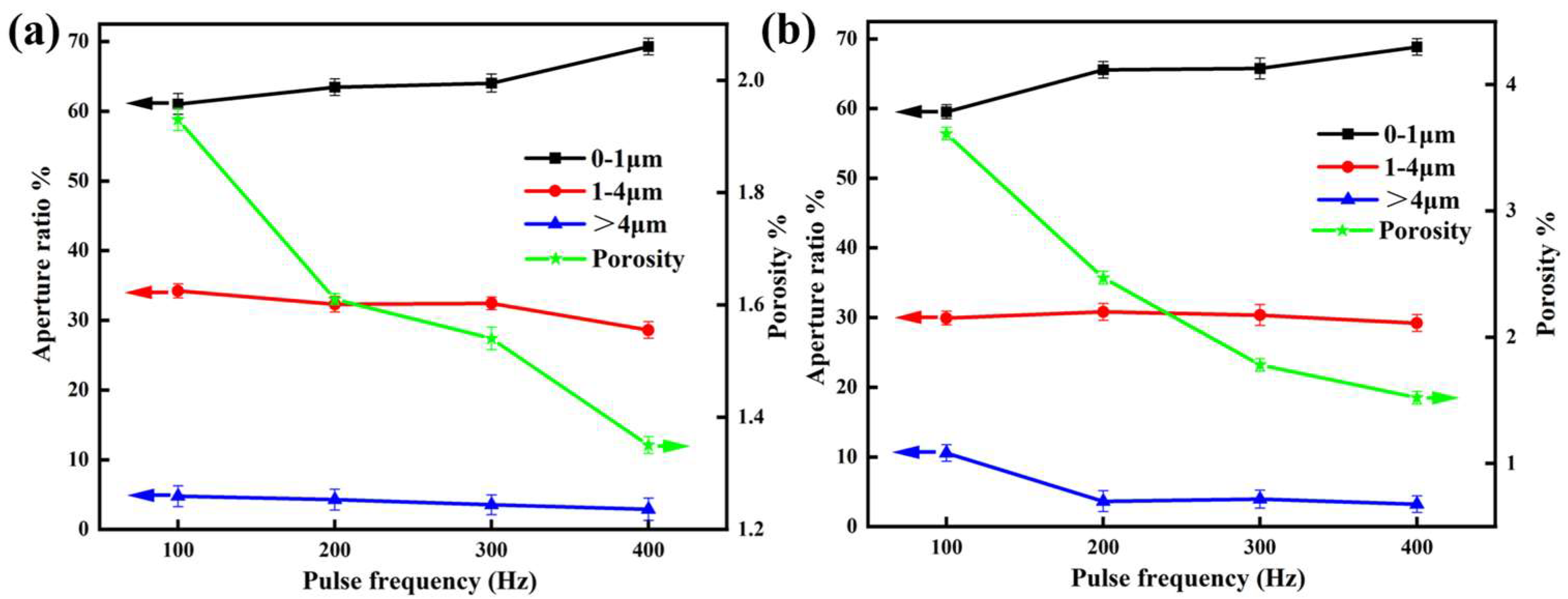
3.2. Surface Morphology of the Composite Coating

Figure 5 presents the surface morphology of MAO coatings and EBR-MAO coatings at different pulse frequencies. The coated surface has numerous micropores, which are mostly circular or elliptical in shape. The microstructure of micro-arc oxidation (MAO) coatings, characterized by these micropores, is one of its distinctive features. The formation mechanism of these micropores is closely related to the localized high-temperature melting and rapid cooling processes during micro-arc discharge. The diameter of these micropores typically ranges from sub-micron to several microns, with the specific size largely dependent on process parameters (such as pulse frequency, voltage, electrolyte composition, etc.) and the substrate material. These micropores are usually unevenly distributed, varying in size and shape, and are primarily located on the surface and within the coating. At low pulse frequencies, the micropores are larger and unevenly distributed, potentially forming interconnected channels; whereas at high pulse frequencies, the size of the micropores decreases, their shape becomes more regular, distribution more uniform, the surface smoother, and they are predominantly sub-micron in size.
Figure 6 illustrates the porosity and aperture ratio of these coatings, as analyzed using lmageJ 1.53c software. The results reveal that the porosity of EBR-MAO coatings is consistently lower than that of MAO coatings, with the porosity of EBR-MAO coatings reaching a minimum of 1.35% at 400 Hz. However, the porosity of both coatings varies with pulse frequency. At 100 Hz, the porosity of the EBR-MAO coating is significantly lower than that of the MAO coating. As the pulse frequency increases, the difference in porosity between the two types of coatings gradually diminishes. It can be attributed to the decrease in single-pulse duration and corresponding pulse energy at higher frequencies during the MAO process. As a result, the pores generated by each pulse become smaller, and the amount of molten material ejected from these pores decreases, leading to more uniform coating deposition.
In addition, the results show that with increasing pulse frequency, the proportion of micropores in the range of 0–1 μm gradually increases. When the pulse frequency increases from 100 to 300 Hz, the proportion of 0–1 μm pores approaches 60%, and at 400 Hz, it rises to nearly 70%. In contrast, the proportion of large pores (>4 μm) decreases significantly, while the proportion of medium-sized pores (1–4 μm) remains relatively stable. This indicates that high-frequency pulses help suppress the formation of large pores and promote the generation of finer micropores, resulting in a more uniform and compact coating structure. Meanwhile, the porosity shows a clear decreasing trend. As shown in Figure 6b, the porosity decreases from 3.61% to approximately 1.6%, and in Figure 6a, it decreases from 1.93% to about 1.3%. This suggests that increasing the pulse frequency can effectively reduce the overall porosity of the coating. This trend can be attributed to the lower energy and shorter duration of each discharge event at higher frequencies, which reduces intense local melting and surface ablation, thus favoring the formation of a stable, fine-pored ceramic layer.
Overall, appropriately increasing the pulse frequency is an effective strategy to optimize the pore structure of MAO coatings, enhancing both their compactness and corrosion resistance. Especially after electron-beam remelting, the coating’s microstructural uniformity and overall stability are further improved, providing a solid structural foundation for enhanced corrosion protection.

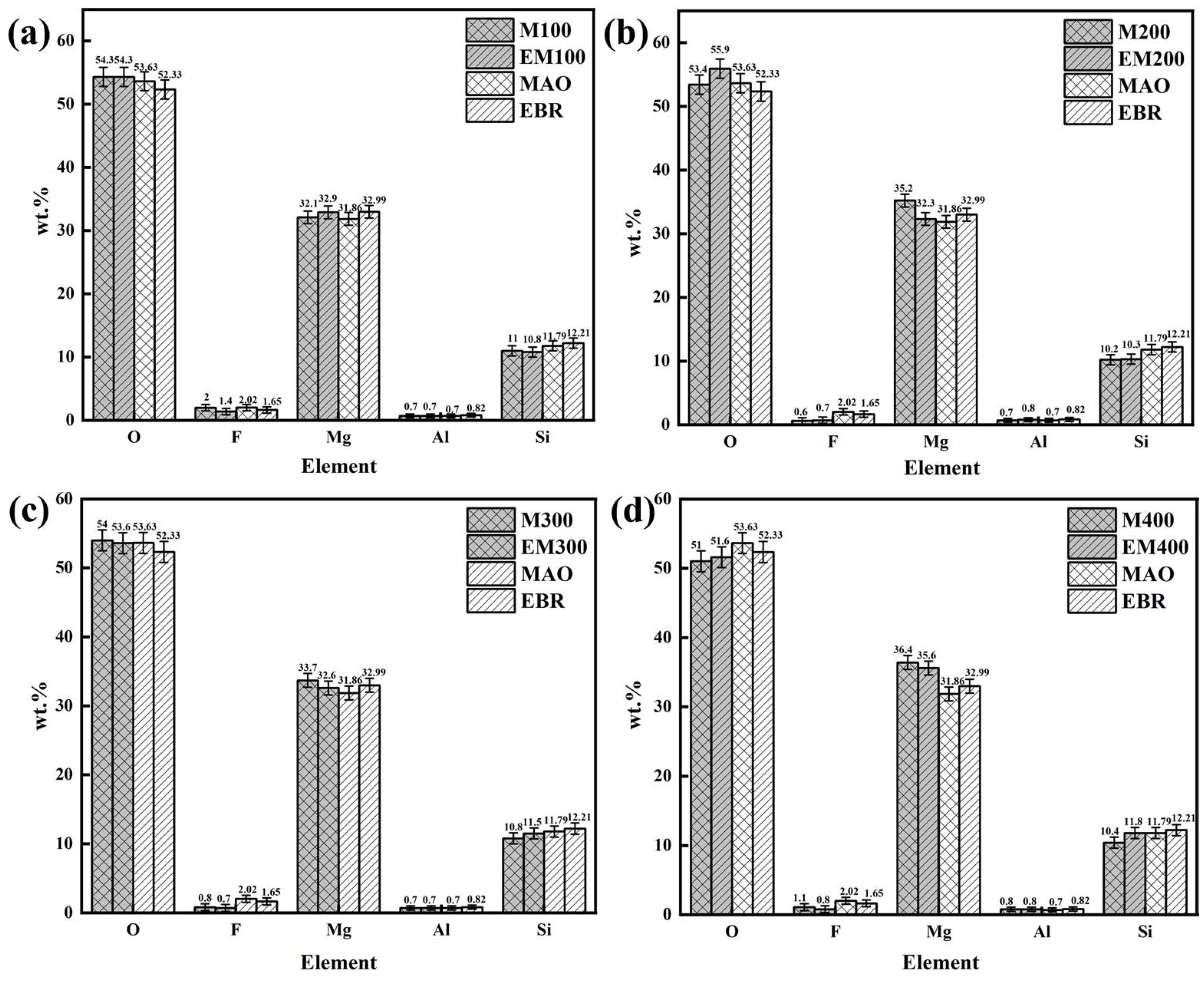
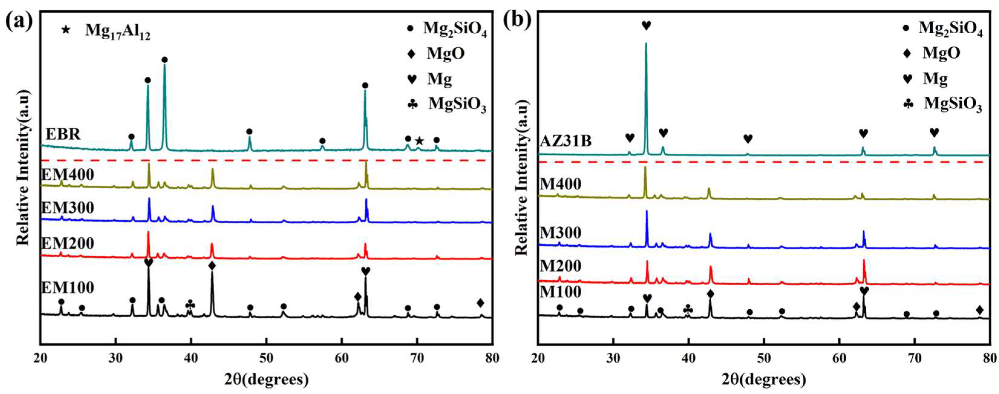
3.3. Composition of the Composite Coating

Figure 7 shows the EDS elemental composition analysis of MAO and EBR-MAO coatings at pulse frequencies ranging from 100 Hz to 400 Hz. The results indicate that the relative content of Mg element in both MAO and EBR-MAO coatings reaches its maximum at 400 Hz. This indicates that when the pulse frequency is 400 Hz, more magnesium remains in the film during the micro-arc oxidation process rather than being ejected from the film surface.
Comparing the Si content in MAO and EBR-MAO coatings across different pulse frequencies, it is observed that the Si content does not change significantly after remelting at frequencies of 100–200 Hz. However, at 300–400 Hz, the increase in Si content becomes more pronounced. Specifically, at 400 Hz, the Si content in the EBR-MAO coating rises from 10.4% to 11.8% compared to the MAO coating. This increase in Si content indicates greater participation of the electrolyte in the reaction, which aligns with the observed increase in the thickness of the EBR-MAO coating compared to the MAO coating under the same parameters.
Additionally, Figure 8 includes the XRD patterns of MAO coatings at different pulse frequencies with and without electron-beam remelting. The analysis reveals that the phases present in the coatings remain consistent with and without remelting, primarily consisting of Mg, MgO, Mg2-SiO4, and Mg2-SiO3 phases. MgO is the first oxide formed during the micro-arc oxidation (MAO) process. It suppresses redox reactions and delays the penetration of corrosive media (such as Cl) into the metallic substrate. Due to its extremely low electrical conductivity, MgO effectively increases the charge transfer resistance (Rt) of the coating. However, MgO forms rapidly under MAO conditions and tends to have a porous structure, often accompanied by microcracks, which may serve as potential corrosion pathways. Mg2-SiO4 is typically formed through the reaction between SiO32− ions from the electrolyte and magnesium ions. It deposits in nanoscale or microscale dimensions within the microcracks and pores of the MgO layer, effectively sealing these defects and enhancing the overall coating density. As a high-hardness ceramic phase, Mg2-SiO4 possesses excellent structural stability, contributing to improved electrochemical stability. Furthermore, Mg2-SiO4 has very poor conductivity for both electrons and ions, thus further enhancing the impedance of the coating.
In summary, MgO plays a role in rapid film formation and provides basic protection, while Mg2-SiO4 contributes to densification and long-term stability. The synergistic effect of these two phases results in a high-performance MAO coating.
This consistency suggests that the porous structure of the MAO coatings allows X-rays to penetrate easily, corroborating the SEM analysis results. Furthermore, the pulse frequency does not significantly influence the phase composition of the EBR-MAO coatings. The Mg peaks observed in the XRD patterns are primarily attributed to the substrate.

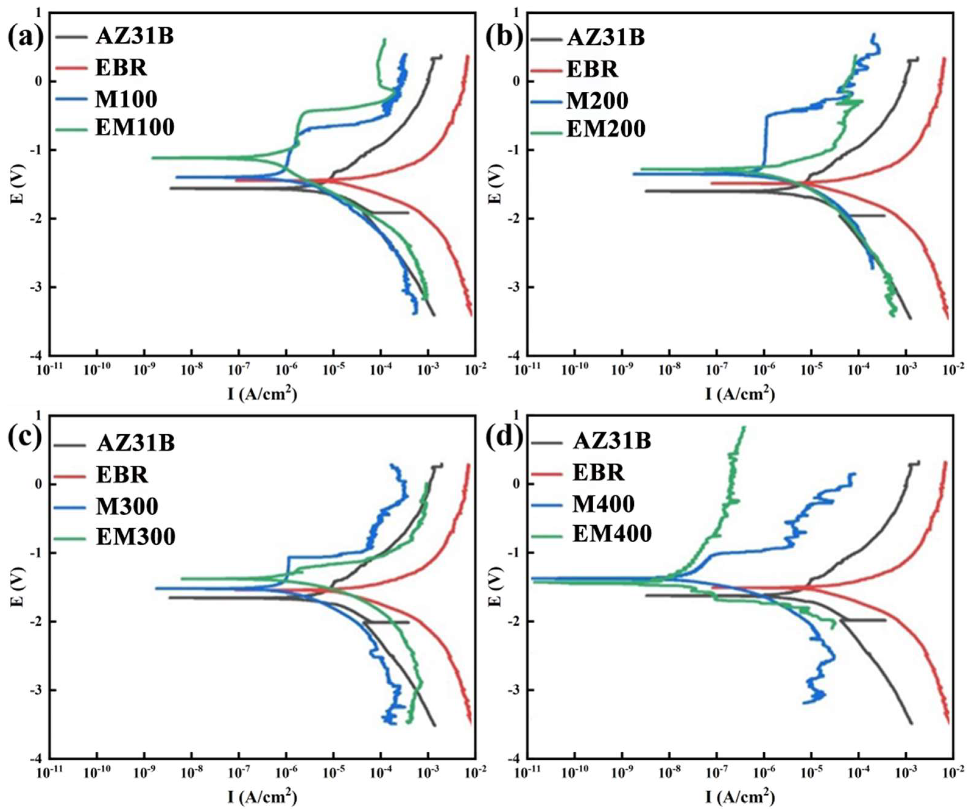
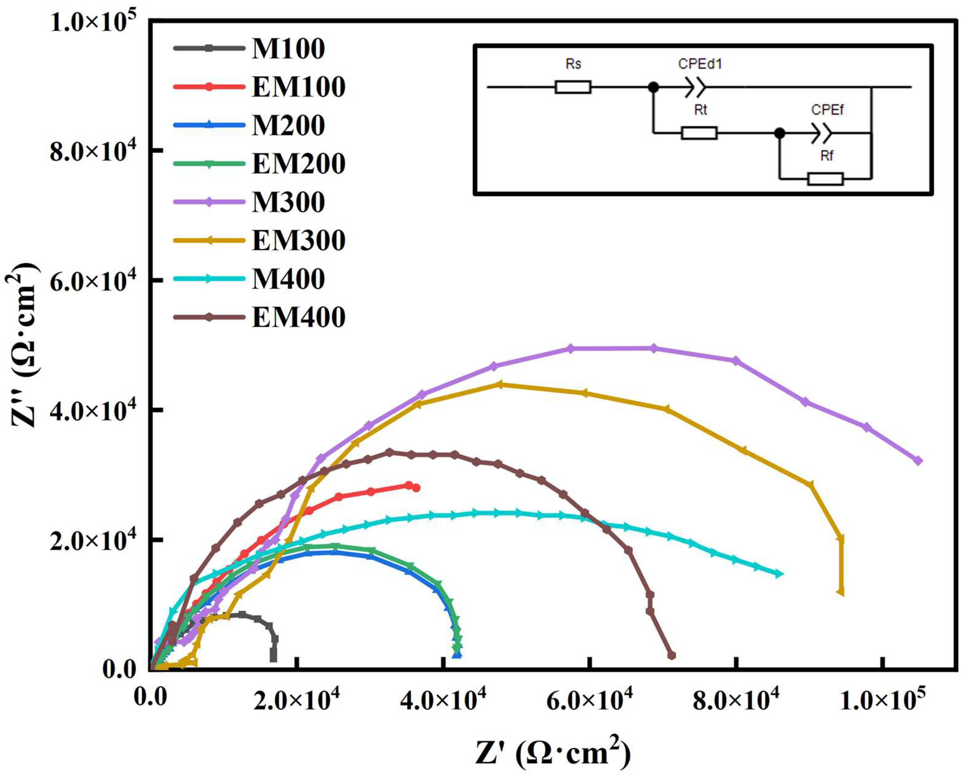
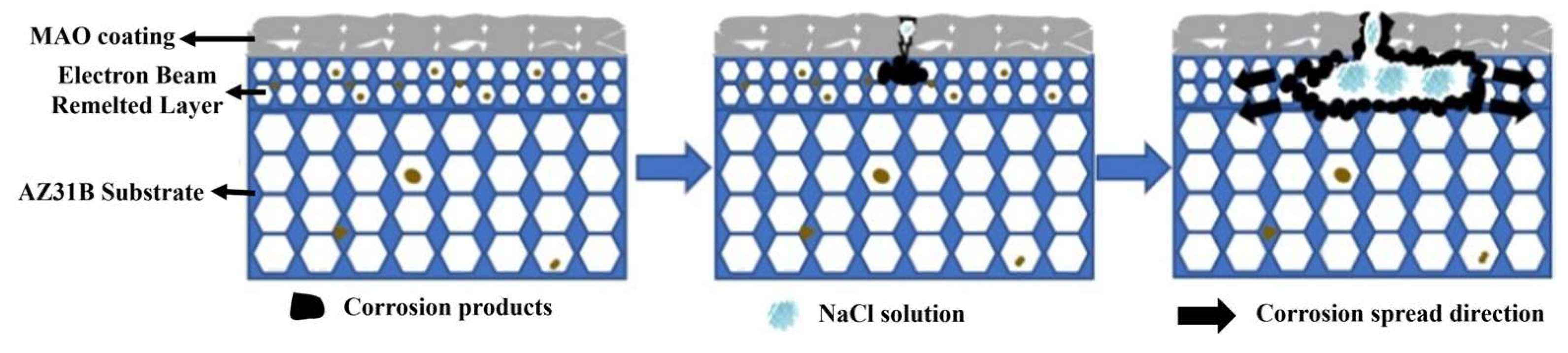
3.4. Corrosion Resistance of the Composite Coating

Figure 9 displays the potentiodynamic polarization curves of MAO and EBR-MAO coatings at different pulse frequency parameters, while Table 1 provides the fitted values for the self-corrosion potential Ecorr and corrosion current density Icorr. From Table 1, it is evident that the Ecorr of the magnesium alloy substrate increased from −1.672 V to −1.521 V after electron-beam remelting. At pulse frequencies ranging from 100 Hz to 300 Hz, the Ecorr of the EBR-MAO coating is higher than that of the MAO coating. Notably, at 100 Hz, the Ecorr of the EBR-MAO coating reaches its highest value of −1.162 V.
Furthermore, at all tested pulse frequencies, the corrosion current density Icorr of the EBR-MAO coating is reduced by an order of magnitude compared to that of the MAO coating. At 400 Hz, the Icorr of the EBR-MAO coating reaches its lowest value of 2.897 × 10⁻⁸ A·cm−2. As shown in Figure 6a, the porosity of the coating also reaches its minimum value at 400 Hz. Combining the results from Figure 3h, it is clear that at 400 Hz, the coating exhibits the most complete bonding with the substrate, and the micro-discharge channels within the structure are uniformly distributed. These factors collectively contribute to the superior corrosion resistance of the EBR-MAO coating at this frequency.
Figure 10 presents the Nyquist curves of MAO and EBR-MAO coatings at different pulse frequencies. As observed, all samples exhibit typical semicircular characteristics, indicating that the charge transfer process plays a dominant role in the corrosion mechanism. In comparison, the samples treated with electron-beam remelting generally show larger semicircular radii, suggesting higher charge-transfer resistance (Rt) and thus better corrosion resistance. Among them, the EM400 sample exhibits the largest impedance, indicating the best corrosion resistance, which may be attributed to its dense and uniform surface film that effectively hinders Cl ion penetration and localized corrosion.
To further quantitatively analyze the electrochemical behavior of the different samples, the equivalent circuit model shown in Figure 9 was used for fitting. The model consists of the following elements: Rs represents the solution resistance, Rt is the charge-transfer resistance, Rf denotes the film resistance, CPEdl represents the constant phase element of the double layer, and CPEf corresponds to the constant phase element of the surface film. The fitting results are presented in Table 2.
At pulse frequencies of 100 Hz and 400 Hz, the Rf value of EBR-MAO coatings increases by an order of magnitude compared to MAO coatings, indicating that the remelted layer significantly enhances long-term corrosion resistance. The Rf value reaches the highest value of 4.57 × 10⁵ Ω·cm2 at 400 Hz. In contrast, at pulse frequencies of 200 Hz and 300 Hz, the Rt and Rf values of the MAO coating with and without EBR show no significant difference, and the Nyquist curves reveal that the capacitance arc radii of the two coatings are similar.
Combining the insights from the polarization curves (Figure 9) and AC impedance spectra (Figure 10), it is clear that at a pulse frequency of 400 Hz, the MAO coating exhibits the lowest porosity, with most pores being micropores (0–1 μm), and demonstrates the best corrosion resistance. As is well known, once the breakdown potential is reached, micro-discharges occur at the metal/electrolyte interface. The presence of interconnected pores, particularly in coatings formed at lower pulse frequencies, can serve as channels for corrosive solutions to penetrate the coating. However, as the pulse frequency increases, the bonding at the metal/electrolyte interface becomes denser, and the coating’s compact structure effectively hinders the penetration of corrosive solutions, thereby significantly enhancing the anti-corrosion capability of the coating.
Pulse frequency has a significant influence on the microstructure and corrosion resistance of EBR-MAO composite coatings on magnesium alloys. In the composite coating system, the electron-beam remelting (EBR) process markedly improves the density of the substrate surface and refines the grain structure, providing a more stable interface foundation for the subsequent MAO treatment. As the MAO pulse frequency increases, the discharge behavior becomes more uniform and the discharge intensity weakens, resulting in fewer surface micropores, smaller pore sizes, and a denser outer-layer structure. These structural characteristics help inhibit the penetration and migration of corrosive media, particularly Cl ions, thereby slowing down the corrosion process.
In contrast, low-frequency discharge tends to cause localized overheating and the formation of larger pores, creating corrosion-sensitive regions that facilitate the penetration of Cl ions and the initiation of pitting corrosion at the coating–substrate interface. Under appropriate high-frequency conditions, the content of Mg, MgO, Mg2-SiO4, and Mg2-SiO3 phases in the coating increases, enhancing the bonding strength and forming a multilayered, multi-impedance protective system. This effectively improves the corrosion resistance of the composite coating. The corresponding corrosion mechanism is illustrated in Figure 11.

4. Conclusions

(1)
Pulse frequency significantly influences the morphology of MAO and EBR-MAO coatings. As the pulse frequency increases, the proportion of micropores (0–1 μm) on the surface of EBR-MAO coatings rises from 61.03% to 69.27%, while the porosity gradually decreases from 1.93% to 1.35%. EBR-MAO coatings are denser especially at high frequency 400 Hz.
(2)
The thickness of both MAO and EBR-MAO coatings decreases with increasing pulse frequency. Compared to MAO coatings, the thickness of the EBR-MAO coatings decreases slowly.
(3)
The corrosion resistance of EBR-MAO coatings is consistently higher than that of MAO coatings at different pulse frequencies. At 400 Hz, Icorr of the EBR-MAO coating reaches its lowest value of 2.897 × 10⁻⁸ A·cm−2, and R2 reaches the highest value 4.57 × 10⁵ Ω·cm2.
These findings highlight the critical role of pulse frequency and electron-beam remelting in optimizing the microstructure, adhesion, and corrosion resistance of MAO coatings in magnesium alloys. This study investigated the effect of pulse frequency on the microstructure and corrosion resistance of electron-beam remelting–micro-arc oxidation (EBR-MAO) composite coatings on AZ31B magnesium alloy by controlling a single variable. In future work, orthogonal experiments can be conducted to explore the influence of multiple process parameters on the growth of MAO coatings. Additionally, pore-sealing treatment can be applied to the EBR-MAO coatings to further enhance their corrosion resistance.

Author Contributions

Conceptualization, methodology, investigation, project administration, writing—original draft, funding acquisition, Y.M.; resources, investigation, data curation, Z.Y., J.Z. and J.M.; resources, data curation, M.Z. and Y.H.; supervision, review, and editing, Z.C. and W.Z.; review and editing, supervision, funding acquisition, J.Y. All authors have read and agreed to the published version of the manuscript.

Funding

The work was supported by the National Natural Science Foundation of China (grant number 52375391) and Wenzhou Basic Scientific Research Project (grant number G2023065).

Institutional Review Board Statement

Not applicable.

Informed Consent Statement

Not applicable.

Data Availability Statement

The data that support the findings of this study are available from the corresponding author upon reasonable request.

Conflicts of Interest

The authors declare no conflict of interest.

References

  1. Dou, J.H.; Chen, Y.; Yu, H.J.; Chen, C.Z. Research status of magnesium alloys by micro-arc oxidation: A review. Surf. Eng. 2017, 33, 731–738. [Google Scholar] [CrossRef]
  2. Kaya, A.A. A Review on Developments in Magnesium Alloys. Front. Mater. 2020, 7, 198. [Google Scholar] [CrossRef]
  3. Lin, Z.S.; Wang, T.L.; Yu, X.M.; Sun, X.T.; Yang, H.Z. Functionalization treatment of micro-arc oxidation coatings on magnesium alloys: A review. J. Alloys Compd. 2021, 879, 160453. [Google Scholar] [CrossRef]
  4. She, J.; Chen, J.; Xiong, X.M.; Yang, Y.; Peng, X.D.; Chen, D.L.; Pan, F.S. Research advances of magnesium and magnesium alloys globally in 2023. J. Magnes. Alloys 2024, 12, 3441–3475. [Google Scholar] [CrossRef]
  5. Bai, J.Y.; Yang, Y.; Wen, C.; Chen, J.; Zhou, G.; Jiang, B.; Peng, X.D.; Pan, F.S. Applications of magnesium alloys for aerospace: A review. J. Magnes. Alloys 2023, 11, 3609–3619. [Google Scholar] [CrossRef]
  6. Chen, H.L.; Wang, Y.; He, L.; Zhang, X.Y.; Mei, Y.N.; Wu, T.; Wang, J.; Zheng, Y.; Tang, H. Surface engineering of biodegradable magnesium alloys as orthopedic implant materials: Recent developments and future prospects. Coatings 2025, 15, 191. [Google Scholar] [CrossRef]
  7. Chi, J.W.; Zhang, H.L.; Song, S.Y.; Zhang, W.S.; He, X.Y.; Nong, Z.S.; Cui, X.; Liu, T.; Man, T.N. The impact of pre- and post-treatment processes on corrosion resistance of micro-arc oxidation coatings on mg alloys: A systematic review. Materials 2025, 18, 723. [Google Scholar] [CrossRef]
  8. Wu, T.; Zhang, K.M. Corrosion and protection of magnesium alloys: Recent advances and future perspectives. Coatings 2023, 13, 1533. [Google Scholar] [CrossRef]
  9. Jiang, J.H.; Geng, X.; Zhang, X.B. Stress corrosion cracking of magnesium alloys: A review. J. Magnes. Alloys 2023, 11, 1906–1930. [Google Scholar] [CrossRef]
  10. Kaseem, M.; Fatimah, S.; Nashrah, N.; Ko, Y.G. Recent progress in surface modification of metals coated by plasma electrolytic oxidation: Principle, structure, and performance. Prog. Mater. Sci. 2021, 117, 100735. [Google Scholar]
  11. Yao, W.H.; Wu, L.; Wang, J.F.; Jiang, B.; Zhang, D.F.; Serdechnova, M.; Shulha, T.; Blawert, C.; Zheludkevich, M.L.; Pan, F.S. Micro-arc oxidation of magnesium alloys: A review. J. Mater. Sci. Technol. 2022, 118, 158–180. [Google Scholar] [CrossRef]
  12. Chen, C.A.; Lee, J.L.; Jian, S.Y.; Lee, C.Y.; Ger, M.D. Effect of Surface Activation on the Corrosion Resistance of a MAO/Ni-P Composite Coating on LZ91 Magnesium Alloy. J. Taiwan Inst. Chem. Eng. 2023, 147, 104881. [Google Scholar] [CrossRef]
  13. Xie, Z.H.; Teng, Y.H.; Huang, Z.F.; Feng, P.C.; Yong, Q.W.; Jiang, X.; Wu, L. Corrosion-resistant and superhydrophobic nickel-based composite coating on magnesium alloy. Surf. Coat. Technol. 2025, 496, 131638. [Google Scholar] [CrossRef]
  14. Li, W.; Yang, K.; Yang, J.W.; Zhang, Z.C.; Yang, G. Effect of laser surface melting pretreatment on wear and corrosion properties of micro-arc oxidation coatings on magnesium alloys. Ceram. Int. 2025, 51, 3037–3052. [Google Scholar] [CrossRef]
  15. Wang, Y.J.; Zhang, Y.; Jiang, H.T. Effect of grain size uniformity and crystallographic orientation on the corrosion behavior of Mg-2Zn-1Al bar. Mater. Charact. 2021, 179, 111374. [Google Scholar] [CrossRef]
  16. Huang, S.Y.; Chu, Y.R.; Yang, S.H.; Lee, Y.L. Effect of pause time on microstructure and corrosion resistance in AZ31 magnesium Alloy’s micro-arc oxidation coating. Surf. Coat. Technol. 2023, 475, 130164. [Google Scholar] [CrossRef]
  17. Dong, H.R.; Li, Q.; Xie, D.B.; Jiang, W.G.; Ding, H.J.; Wang, S.; An, L.Y. Forming characteristics and mechanisms of micro-arc oxidation coatings on magnesium alloys based on different types of single electrolyte solutions. Ceram. Int. 2023, 49, 32271–32281. [Google Scholar] [CrossRef]
  18. Bai, L.J.; Dong, B.X.; Chen, G.T.; Xin, T.; Wu, J.N.; Sun, X.D. Effect of positive pulse voltage on color value and corrosion property of magnesium alloy black micro-arc oxidation ceramic coating. Surf. Coat. Technol. 2019, 374, 402–408. [Google Scholar] [CrossRef]
  19. Wang, D.Y.; Yuan, J.; Liu, Q.B. Biodegradable behavior of the micro-arc oxidation coating with micro-nano structure formed by femtosecond laser on magnesium alloy AZ31B. Ceram. Int. 2025, 51, 9864–9876. [Google Scholar] [CrossRef]
  20. Pan, H.K.; Hu, H.H.; Wei, Z.H.; Yang, F.; Fan, Z.S.; Lu, H.L. Investigation on surface properties of AZ31 magnesium alloy modified by micro-arc oxidation and cathodic deposition techniques. Surf. Coat. Technol. 2025, 496, 131599. [Google Scholar] [CrossRef]
  21. Sun, S.; Shang, J. Improvement of corrosion resistance of AZ31 magnesium alloy by laser remelting/microarc oxidation/LDH composite layer. Mater. Lett. 2024, 356, 135531. [Google Scholar] [CrossRef]
  22. Zhao, G.H.; Zhang, P.; Li, J.; Zhang, Z.; Li, H.Y.; Ma, L.F. Effects of different scanning speeds on microstructure evolution and tribological properties of Inconel 718 alloy vacuum electron beam surface modification. Mater. Today Sustain. 2024, 25, 100613. [Google Scholar] [CrossRef]
  23. Niu, S.Q.; Yin, L.X.; You, Q.F.; You, X.G.; Wang, Y.N.; Tan, Y. The alloying elements dispersion and its mechanisms in a Ni-based superalloy during electron beam remelting. Vacuum 2019, 166, 107–113. [Google Scholar] [CrossRef]
  24. Zhao, G.H.; Sun, M.X.; Zhao, H.; Li, J.; Li, H.Y.; Ma, L.F. Study on modification of 253 MA austenitic stainless steel by electron beam surface remelting treatment. Surf. Coat. Technol. 2023, 470, 129834. [Google Scholar] [CrossRef]
  25. Yao, J.Y.; Li, J.; Zhao, G.H.; Li, H.Y.; Ma, L.F.; Liu, J. Microstructure Evolution and Mechanical Properties of TiC Coating over Inconel 625 Obtained by Vacuum Electron Beam Surface Alloying. Metals 2023, 13, 275. [Google Scholar] [CrossRef]
  26. Ma, Y.H.; Mei, J.H.; Ouyang, J.X.; Wu, P.; Wang, S.; Yang, J.G.; He, Y.M.; Zheng, W.J.; Li, H.X.; Lu, C.Y.; et al. Structure and corrosion resistance of electron-beam-strengthened and micro-arc oxidized coatings on magnesium alloy AZ31. J. Vac. Sci. Technol. A 2023, 41, 53101. [Google Scholar] [CrossRef]
  27. Zhao, J.H.; Wen, F.L.; Gu, C.; Gao, L.S.; Zhang, J.Y. Effect of vacuum induction heat treatment on the formation of intermetallic compounds between electroplated Ni coating and TC4 alloy. Vacuum 2021, 191, 110380. [Google Scholar] [CrossRef]
Figure 1. Flow chart of EBR-MAO process.
Materials 18 01962 g001
Figure 2. Three-dimensional surface morphology with and without remelting: (a) electron-beam remelting; (b) AZ31B.
Materials 18 01962 g002
Figure 3. Cross-sectional morphologies of MAO coatings with and without beam remelting under different pulse frequencies: (ad) M100, M200, M300, M400; (eh) EM100, EM200, EM300, EM400.
Materials 18 01962 g003
Figure 4. Thickness of MAO coating with and without electron-beam remelting under different pulse frequencies.
Materials 18 01962 g004
Figure 5. The surface morphology and pore distribution of MAO coatings with and without electron-beam remelting under different pulse frequencies: (a,a′d,d′) M100, M200, M300, M400; (e,e′h,h′) EM100, EM200, EM300, EM400.
Materials 18 01962 g005
Figure 6. Surface porosity and pore size ratio of MAO coating with and without electron-beam remelting at different pulse frequencies: (a) EBR-MAO coatings; (b) MAO coatings.
Materials 18 01962 g006
Figure 7. An analysis of the proportion of EDS elements in MAO coating with and without electron-beam remelting under different pulse frequencies. (a) 100 Hz, (b) 200 Hz, (c) 300 Hz, (d) 400 Hz.
Materials 18 01962 g007
Figure 8. XRD patterns of MAO coating with and without electron-beam remelting under different pulse frequencies: (a) EBR-MAO coatings; (b) MAO coatings.
Materials 18 01962 g008
Figure 9. Polarization curves of MAO coating with and without electron-beam remelting under different pulse frequencies. (a) 100 Hz, (b) 200 Hz, (c) 300 Hz, (d) 400 Hz.
Materials 18 01962 g009
Figure 10. Nyquist curve of MAO coating with and without electron-beam remelting under different pulse frequencies.
Materials 18 01962 g010
Figure 11. Corrosion mechanism diagram of EBR-MAO treated magnesium alloy.
Materials 18 01962 g011
Table 1. Polarization-curve parameters of MAO coating with and without electron-beam remelting under different pulse frequencies.
Ecorr/VIcorr/(A·cm−2)
AZ31B−1.6721.607 × 10−5
EBR−1.5211.144 × 10−5
M100−1.4602.012 × 10−6
EM100−1.1626.423 × 10−7
M200−1.3671.929 × 10−6
EM200−1.2955.681 × 10−7
M300−1.4871.802 × 10−6
EM300−1.3374.238 × 10−7
M400−1.3641.261 × 10−7
EM400−1.4382.897 × 10−8
Table 2. Nyquist fitting data of MAO coating with and without electron-beam remelting under different pulse frequencies.
Rs
(Ω·cm2)
CPEd1
−1sncm−2)
N1Rt
(Ω·cm2)
CPEf
−1sncm−2)
N2Rf
(Ω·cm2)
AZ31B33.151.33 × 10−60.934.20 × 1021.25 × 10−60.911.64 × 103
EBR39.568.77 × 10−60.956.40 × 1024.99 × 10−71.061.69 × 103
M10048.301.38 × 10−70.724.60 × 1044.44 × 10−80.842.22 × 104
EM10035.263.24 × 10−70.786.08 × 1045.99 × 10−70.691.14 × 104
M20034.63.69 × 10−80.804.24 × 1042.22 × 10−70.793.05 × 104
EM20030.65.67 × 10−80.785.14 × 1042.80 × 10−80.864.81 × 104
M30044.64.62 × 10−80.847.54 × 1041.59 × 10−80.872.35 × 104
EM30034.23.54 × 10−80.808.34 × 1041.09 × 10−80.788.41 × 104
M40033.21.18 × 10−70.955.36 × 1043.97 × 10−70.894.15 × 104
EM40032.73.34 × 10−70.875.89 × 1043.97 × 10−80.794.57 × 105
Disclaimer/Publisher’s Note: The statements, opinions and data contained in all publications are solely those of the individual author(s) and contributor(s) and not of MDPI and/or the editor(s). MDPI and/or the editor(s) disclaim responsibility for any injury to people or property resulting from any ideas, methods, instructions or products referred to in the content.

