
Process and Properties of Al-Mg-Er-Zr-Sc High-Strength Aluminum Alloy Powder Prepared by Vacuum Induction Melting Gas Atomization


 , , ,
, , ,
Abstract
1. Introduction
2. Numerical Models and Calculation Methods
3. Experimental Design and Methods
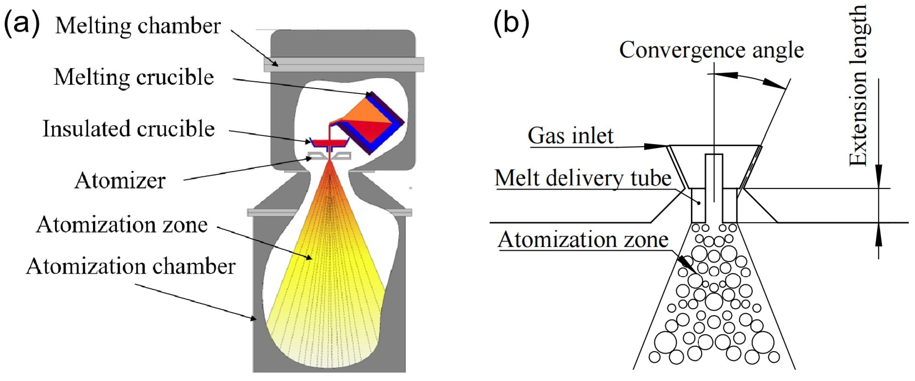
3.1. Powder Preparation
3.2. Powder Performance Testing
3.3. LPBF Process
4. Experimental Results and Discussion
4.1. Numerical Calculation Result and Experimental Verification
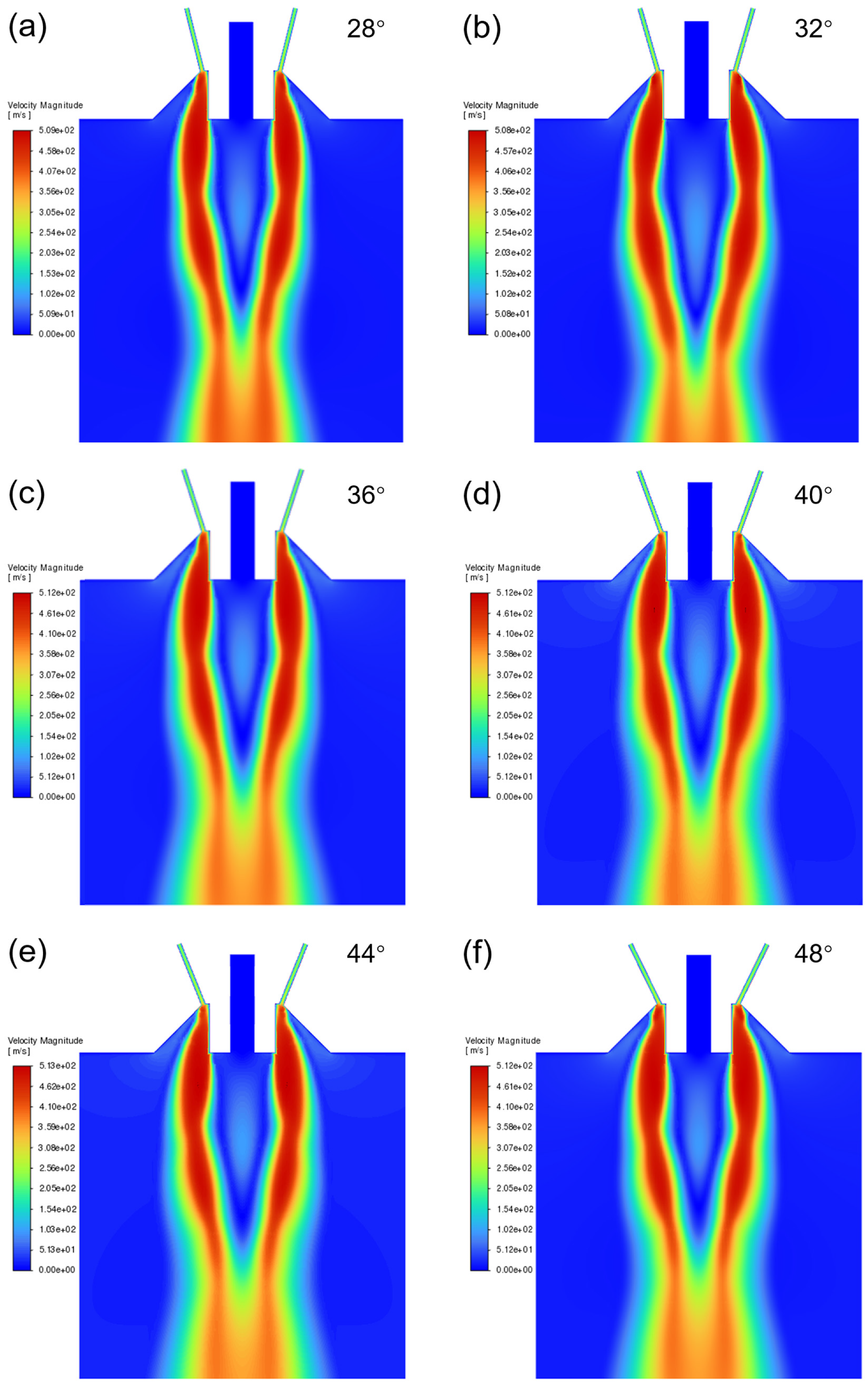
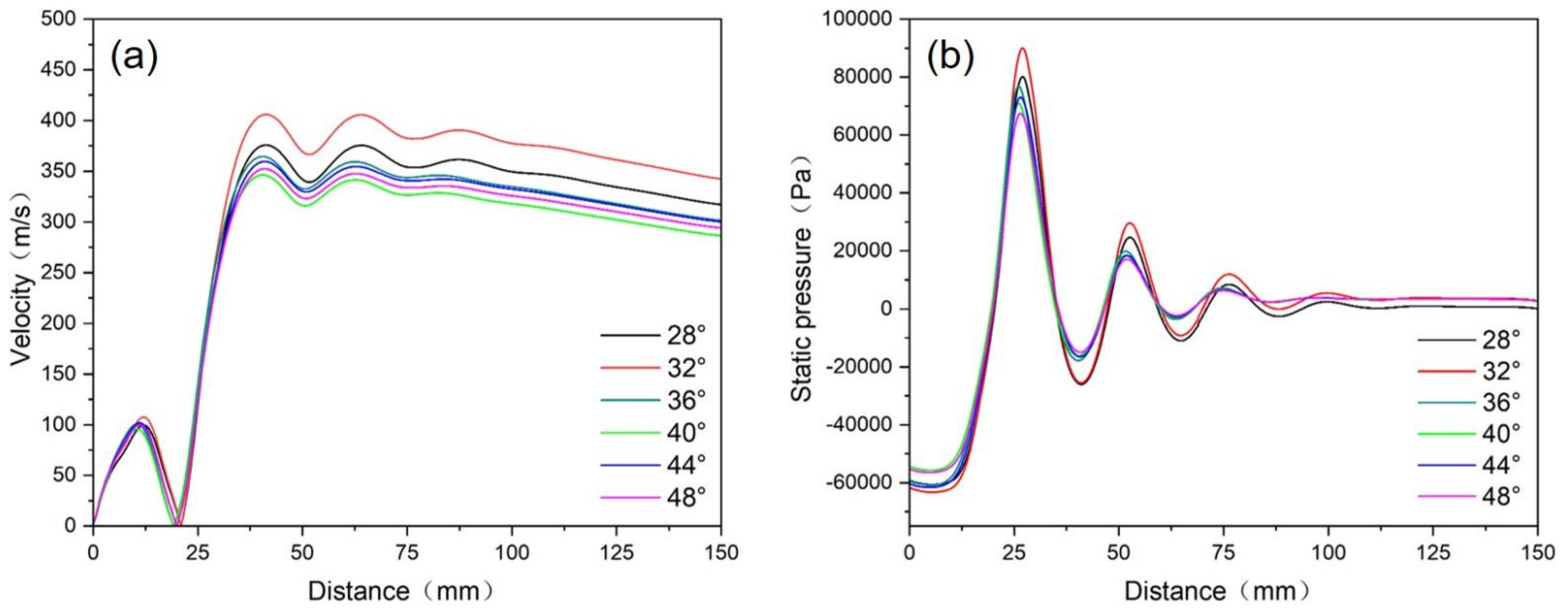
4.1.1. Research on Convergence Angle of Atomizer Nozzle
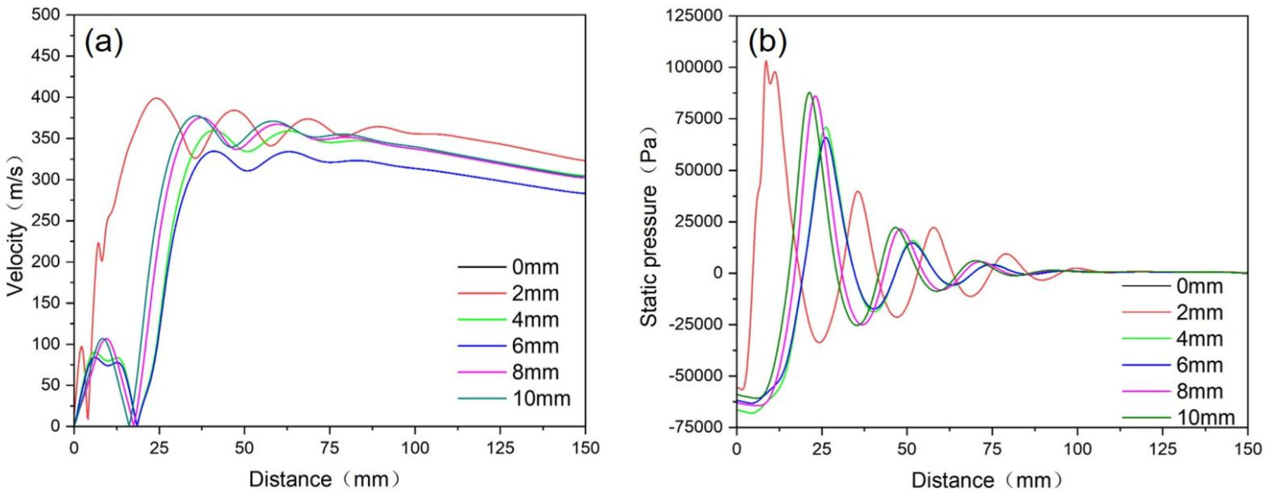
4.1.2. Research on the Extension Length of the Melt Delivery Tube
4.1.3. Experimental Verification
4.2. Research on Melt Temperature and Atomization Pressure
4.3. Powder Performance
4.4. LPBF-Processed Part Performance
5. Conclusions
- When the convergence angle was 32° and the extension length was 5 mm, the large negative pressure and suction force at the tube outlet could facilitate the smooth flow of the melt and a suitable powder particle size distribution was obtained.
- When the melt temperature was 800 °C and the atomization pressure was 3.25 Mpa, the melt had low viscosity and the atomization gas could fully interact with the melt. Meanwhile, atomized droplets had suitable cooling conditions, avoiding the generation of irregular powder and improving the powder sphericity. Under the optimal processing parameters, the prepared powders were spherical or nearly spherical with fine particle size and a high yield of about 39.45%.
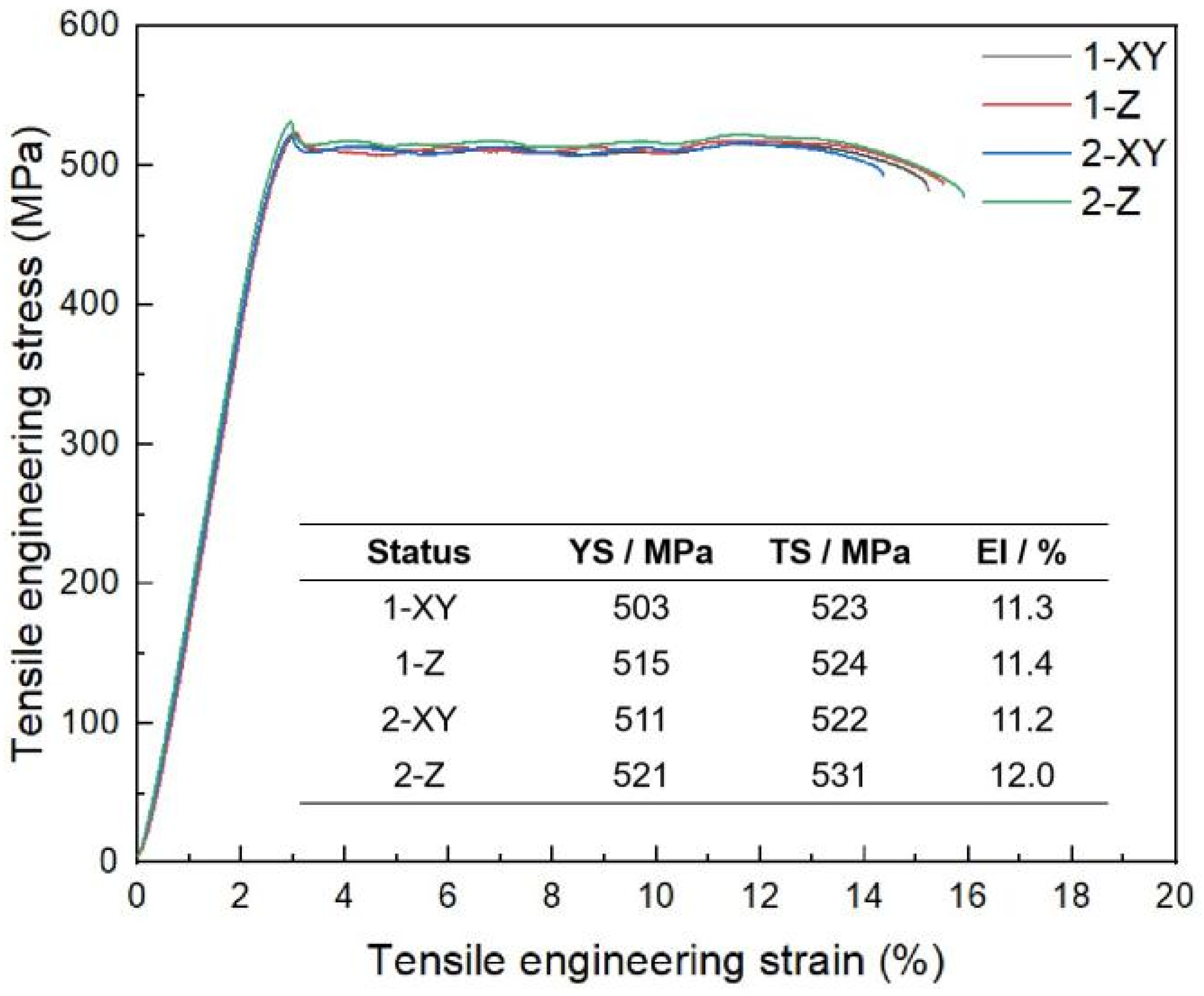
- The LPBF-processed Al-Mg-Er-Zr-Sc high-strength aluminum alloy exhibited excellent mechanical properties, with a tensile strength of over 520 MPa, a yield strength of over 500 MPa, and an elongation of over 11%.
Author Contributions
Funding
Institutional Review Board Statement
Informed Consent Statement
Data Availability Statement
Conflicts of Interest
References
- Chang, K.; Liang, E.; Zhang, R.; Zheng, M.; Wei, L.; Huang, W.; Lin, X. Status of metal additive manufacturing and its application research in the field of civil aviation. Mater. Rep. 2021, 35, 3176–3182. [Google Scholar]
- Spierings, A.B.; Dawson, K.; Kern, K.; Palm, F.; Wegener, K. SLM-processed Sc- and Zr- modified Al-Mg alloy: Mechanical properties and microstructural effects of heat treatment. Mater. Sci. Eng. A 2017, 701, 264–273. [Google Scholar] [CrossRef]
- Jia, Q.; Rometsch, P.; Kürnsteiner, P.; Chao, Q.; Huang, A.; Weyland, M.; Bourgeois, L.; Wu, X. Selective laser melting of a high strength Al-Mn-Sc alloy: Alloy design and strengthening mechanisms. Acta Mater. 2019, 171, 108–118. [Google Scholar] [CrossRef]
- Spierings, A.B.; Dawson, K.; Uggowitzer, P.J.; Wegener, K. Influence of SLM scan-speed on microstructure, precipitation of Al3Sc particles and mechanical properties in Sc- and Zr-modified Al-Mg alloys. Mater. Des. 2018, 140, 134–143. [Google Scholar] [CrossRef]
- Gao, Z.; Ma, T.; Li, H.; Huang, H.; Nie, Z. Microstructure and mechanical properties of a novel AlMgErZrSc alloy fabricated by selective laser melting. Mater. Res. Technol. 2023, 27, 6880–6891. [Google Scholar] [CrossRef]
- Available online: http://amreference.com/?p=22196 (accessed on 25 September 2024).
- Liu, J.; Liu, Y.; Wang, C.; Yu, X.; Liu, Z.; Wang, R.; Bi, Z.; Liang, J. Numerical simulation and experimental validation on preparation of 18Ni250 steel powder by VIGA process. Iron Steel 2024, 59, 112–121. [Google Scholar]
- Bi, J.; Wei, W.; Guo, Y.; Qi, P.; Shi, W.; Zhou, X.; Wen, S.; Huang, H.; Nie, Z. Evolution of multi-cellular structure on Zr and Er modified Al6Si1Mg alloy fabricated by laser powder bed fusion. J. Mater. Res. Technol. 2023, 25, 398–410. [Google Scholar] [CrossRef]
- Guo, Y.W.; Wei, W.; Shi, W.; Xue, D.; Zhou, X.R.; Wen, S.P.; Wu, X.L.; Gao, K.Y.; Huang, H.; Nie, Z.R. Selective laser melting of Er-modified AlSi7Mg alloy: Effect of processing parameters on forming quality, microstructure, and mechanical properties. Mater. Sci. Eng. A 2022, 842, 143085. [Google Scholar] [CrossRef]
- Guo, Y.; Wei, W.; Shi, W.; Zhang, B.; Zhou, X.; Wen, S.; Wu, X.; Gao, K.; Rong, L.; Huang, H.; et al. Effect of Er and Zr additions and aging treatment on grain refinement of aluminum alloy fabricated by laser powder bed fusion. J. Alloy. Compd. 2022, 912, 165237. [Google Scholar] [CrossRef]
- Tsirlis, M.; Michailidis, N. Low-pressure gas atomization of aluminum through a venturi nozzle. Adv. Powder Technol. 2020, 31, 1720–1727. [Google Scholar] [CrossRef]
- Pinotti, V.E.; Andreoli, A.F.; Gargarella, P. Gas atomization of AA2017 aluminum alloy: Effect of process parameters in the physical properties of powders for additive manufacturing. J. Mater. Res. Technol. 2024, 30, 3650–3662. [Google Scholar] [CrossRef]
- Liu, Y.; Li, Z.; Xu, W.; Yuan, H. Flow fields simulation of nozzle construction of spray forming atomizer. Powder Metall. Tech. 2014, 32, 87–91. [Google Scholar]
- Zhang, G.; Zhang, Y.; Zheng, L.; Peng, Z. Research progress in powder metallurgy superalloys and manufacturing technologies for aero-engine application. Acta Metall. Sin. 2019, 55, 1133–1143. [Google Scholar]
- Lubandska, H. Correlation of spray ring data for gas atomization of liquid metals. J. Miner. Met. Mater. Soc. 1970, 22, 45–49. [Google Scholar] [CrossRef]
- Chen, M. Research on the Impact of Vacuum Atomization Nozzle Parameters on Flow Field Characteristics and Atomization Metal Particle Size Based on CFD. Master’s Thesis, Ningxia University, Yinchuan, China, 2022. [Google Scholar]
- Ünal, R. The influence of the pressure formation at the tip of the melt delivery tube on tin powder size and gas/melt ratio in gas atomization method. J. Mater. Process. Technol. 2006, 180, 291–295. [Google Scholar] [CrossRef]
- Ting, J.; Peretti, M.W.; Eisen, W.B. The effect of wake-closure phenomenon on gas atomization performance. Mater. Sci. Eng. A 2002, 326, 110–121. [Google Scholar] [CrossRef]
- Urionabarrenetxea, E.; Avello, A.; Rivas, A.; Martín, J.M. Experimental study of the influence of operational and geometric variables on the powders produced by close-coupled gas atomization. Mater. Des. 2021, 199, 109441. [Google Scholar] [CrossRef]
- Xu, X.; Lu, L.; Wu, W. Research progress of close-coupled gas atomization based on image and numerical simulation. Powder Metall. Ind. 2023, 33, 118–126. [Google Scholar]
- Sun, J.; Cao, F.; Cui, C.; Shen, J.; Li, Q. Dynamic behaviors of gas velocity field during metal atomization. Powder Metallurgy Tech. 2002, 20, 79–81. [Google Scholar]
- Luo, S.; Wang, H.; Gao, Z.; Wu, Y.; Wang, H. Interaction between high-velocity gas and liquid in gas atomization revealed by a new coupled simulation model. Mater. Des. 2021, 212, 110264. [Google Scholar] [CrossRef]
- Tan, X.; Guo, Z.; Li, C.; Li, C.; Zhang, H.; Su, X. Numerical simulation and experimental study on the influence of the length of guide tube and atomization pressure on gas reflux. Powder Metall. Ind. 2024, 34, 30–36. [Google Scholar]
- Wang, C.; Liu, Y.; Cao, C.; Lang, T.; Ma, C.; Xie, D. Numerical simulation and mechanism analysis of gas atomized pulverizing process for additive manufacturing. Powder Metall. Ind. 2021, 31, 22–28. [Google Scholar]
- Guo, K.; Chen, J.; Liu, C.; Chen, S. Numerical simulation of the intersection angle influence on atomization process of powders produced by VIGA. J. Northeast. Univ. 2020, 41, 729–735. [Google Scholar]
- Ban, W.; Chen, J.; Liu, L.; Ge, T.; Zhang, S. Research on flow field characteristic of close-coupled gas atomizing nozzles. Powder Metall. Technol. 2024, 42, 312–319. [Google Scholar]
- Hou, W.; Wu, J.; Meng, J.; Liang, J.; Li, J. Atomization simulation and preparation of GH3536 powders at different atomization pressures. Powder Metall. Technol. 2023, 41, 410–419. [Google Scholar]
- Si, C.; Zhang, X.; Wang, J. Low-pressure argon atomization process of 7055Al alloy powders. Mater. Sci. Eng. Powder Metall. 2015, 20, 112–117. [Google Scholar]
- Li, X.; Zeng, K.; He, P.; Luo, H.; Zong, W.; Song, X.; Zhu, J. Effect of atomization pressure on particle size and morphology of Inconel 625 alloy powder for selective laser melting. Mater. Sci. Eng. Powder Metall. 2019, 24, 374–378. [Google Scholar]
- Wang, S.; Yu, H.; Wang, H.; Zhang, Z.; Min, G. Microstructure and mechanical properties of Al-Zn-Mg-Cu alloy powders prepared by gas atomization process. Powder Metall. Technol. 2010, 28, 12–16. [Google Scholar]
- Li, S.; Mao, X.; Liang, H.; Hu, Z. Effects of rapid solidification and atomization technology on morphology and size distribution of aluminium alloy powders. Foundry Technol. 2005, 26, 264–267. [Google Scholar]
- Zhong, W.; Jiao, D.; Qiu, W.; Liu, Z. Influence of melt temperature and atomization pressure on argon-atomized nickel-based superalloy powder. Mater. Rep. 2023, 37, 147–152. [Google Scholar]
- Yan, J.; Hodge, A.M. Study of β precipitation and layer structure formation in Al 5083: The role of dispersoids and grain boundaries. J. Alloy. Compd. 2017, 703, 242–250. [Google Scholar] [CrossRef]


| Number | Material System | Brand | Company | Tensile Strength /MPa | Yield Strength /MPa | Elongation /% |
|---|---|---|---|---|---|---|
| 1 | Al-Mg-Er-Zr | HSAL-13 | Avimetal-am | 520 | 500 | 11–13% |
| 2 | Al-Cu-TiB2 | AM205 | Aeromet International | 450–511 | 390–440 | 10–13% |
| 3 | Al-Mg-Sc-Zr | Scalmalloy | The Airbus Apworks | 520 | 480 | 13% |
| 4 | Al-Mg-Sc-Zr | HAlSc | Changsha New Material Industry Research Institute | 535 | 510 | 12% |
| 5 | Al-Mg-Sc-Zr | CRRC-HAP-1 | CRRC Academy | 560 | 500 | 10% |
| 6 | Al-Mg-Sc-Zr | HS5501 | Baohang materials | 530 | 520 | 10% |
| 7 | Al-Mn-Sc-Zr | Al250C | SuZhou Am proinnovations | 590 | 580 | 11% |
| 8 | Al-Cu-Ag | AM 2139 | EOS | 520–540 | 460 | 4–6% |
| Element | Al | Mg | Er | Zr | Sc | Fe | Si | Mn |
|---|---|---|---|---|---|---|---|---|
| Mass ratio (%) | Bal. | 4.50 | 0.70 | 0.50 | 0.30 | 0.30 | 0.30 | 0.50 |
| Parameter | Laser Power | Scan Speed | Scan Spacing | Layer Thickness | Fill Angle |
|---|---|---|---|---|---|
| Numerical value | 280 W | 1200 mm/s | 0.08 mm | 30 μm | 67° |
| Number | Convergence Angle/° | Extension Length/mm |
|---|---|---|
| 2–1 | 28 | 6 |
| 2–2 | 32 | 6 |
| 2–3 | 36 | 6 |
| 2–4 | 40 | 6 |
| 2–5 | 44 | 6 |
| 2–6 | 48 | 6 |
| Number | Convergence Angle/° | Extension Length/mm |
|---|---|---|
| 2–1 | 28 | 5 |
| 2–2 | 28 | 6 |
| 2–3 | 28 | 7 |
| 2–4 | 30 | 5 |
| 2–5 | 30 | 6 |
| 2–6 | 30 | 7 |
| 2–7 | 32 | 5 |
| 2–8 | 32 | 6 |
| 2–9 | 32 | 7 |
| Number | Convergence Angle/° | Extension Length/mm | D50/μm | nρ/% |
|---|---|---|---|---|
| 2-1 | 28 | 5 | 46.43 | 32.64. |
| 2-2 | 28 | 6 | 49.25 | 31.58 |
| 2-3 | 28 | 7 | 54.02 | 29.31 |
| 2-4 | 30 | 5 | 45.24 | 33.59 |
| 2-5 | 30 | 6 | 47.45 | 32.15 |
| 2-6 | 30 | 7 | 52.53 | 30.02 |
| 2-7 | 32 | 5 | 44.65 | 34.53 |
| 2-8 | 32 | 6 | 48.27 | 31.79 |
| 2-9 | 32 | 7 | 56.25 | 28.56 |
| Number | Melt Temperature/°C | Atomization Pressure/MPa |
|---|---|---|
| 3-1 | 750 | 3.0 |
| 3-2 | 750 | 3.25 |
| 3-3 | 750 | 3.50 |
| 3-4 | 800 | 3.0 |
| 3-5 | 800 | 3.25 |
| 3-6 | 800 | 3.50 |
| 3-7 | 850 | 3.0 |
| 3-8 | 850 | 3.25 |
| 3-9 | 850 | 3.50 |
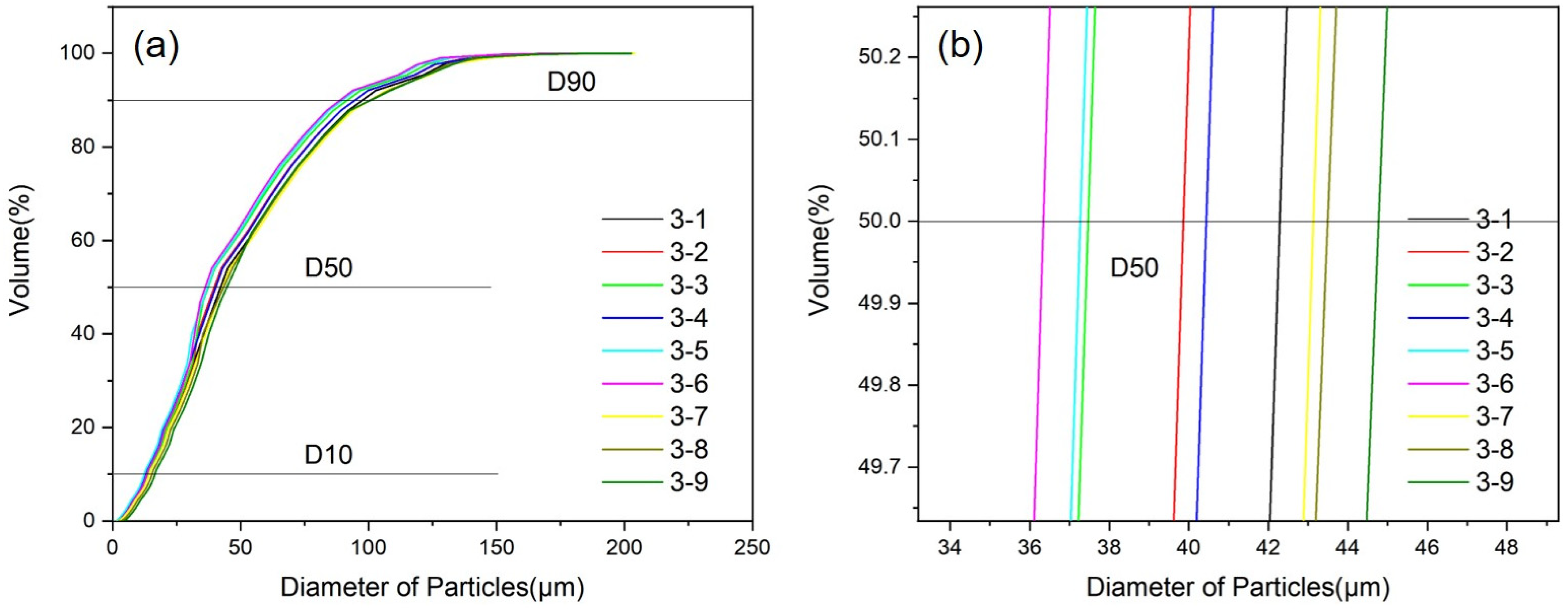
| Number | Melt Temperature/°C | Atomization Pressure/MPa | D50/μm | nρ/% |
|---|---|---|---|---|
| 3-1 | 750 | 3.0 | 44.65 | 34.53 |
| 3-2 | 750 | 3.25 | 41.98 | 36.28 |
| 3-3 | 750 | 3.50 | 40.13 | 36.98 |
| 3-4 | 800 | 3.0 | 39.26 | 37.54 |
| 3-5 | 800 | 3.25 | 37.57 | 39.45 |
| 3-6 | 800 | 3.50 | 38.64 | 38.03 |
| 3-7 | 850 | 3.0 | 43.44 | 35.26 |
| 3-8 | 850 | 3.25 | 42.03 | 36.03 |
| 3-9 | 850 | 3.50 | 41.08 | 36.55 |
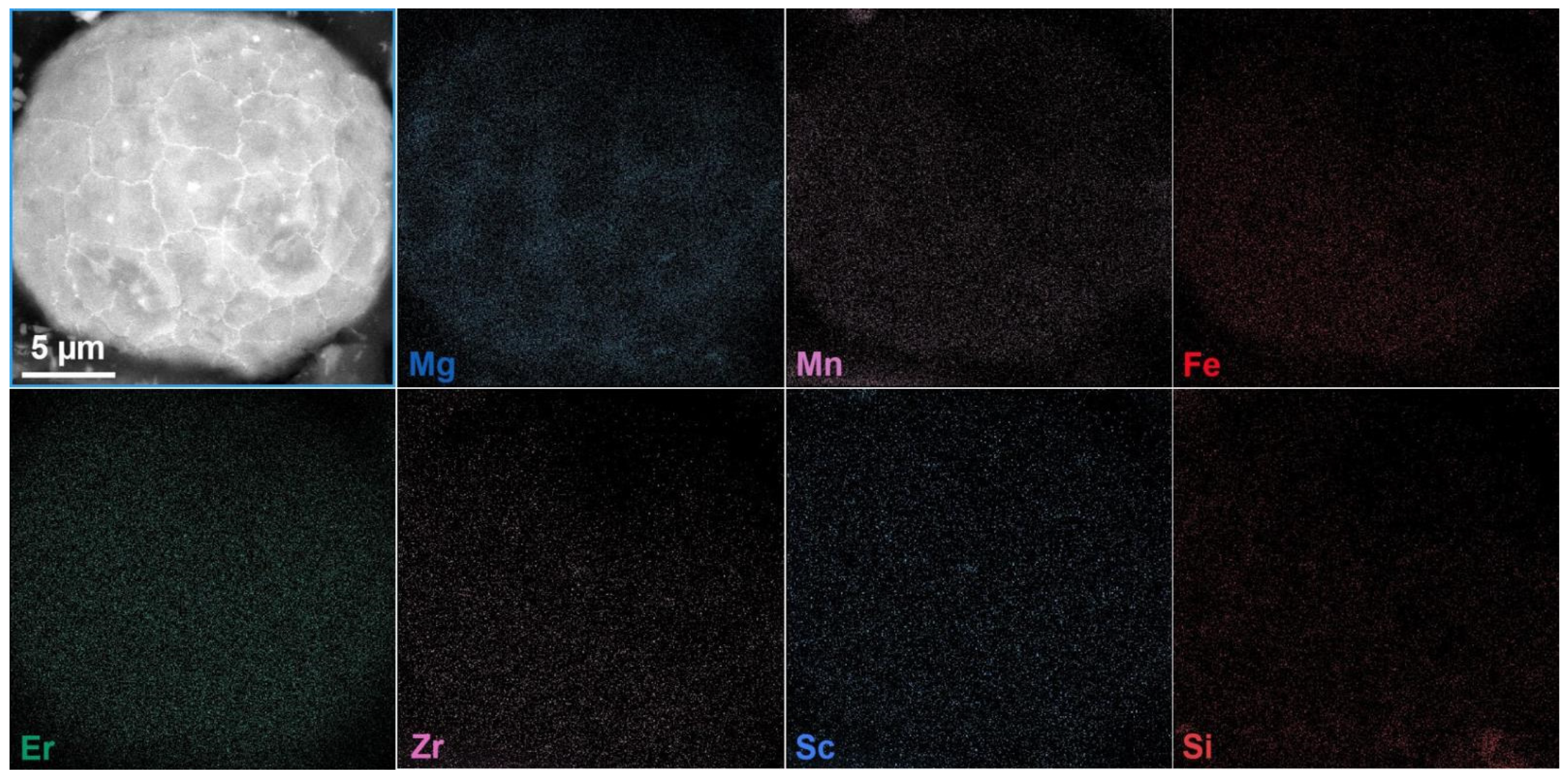
| Element | Al | Mg | Er | Zr | Sc | Fe | Si | Mn | O | N |
|---|---|---|---|---|---|---|---|---|---|---|
| Mass ratio (%) | bal | 4.15 | 0.66 | 0.47 | 0.31 | 0.28 | 0.19 | 0.53 | 0.035 | 0.012 |
| Test Indicators | Apparent Density/g/cm3 | Tap Density/g/cm3 | Hall Flow Rate/s/50 g |
|---|---|---|---|
| Numerical value | 1.13 | 1.36 | 75 |
Disclaimer/Publisher’s Note: The statements, opinions and data contained in all publications are solely those of the individual author(s) and contributor(s) and not of MDPI and/or the editor(s). MDPI and/or the editor(s) disclaim responsibility for any injury to people or property resulting from any ideas, methods, instructions or products referred to in the content. |
© 2025 by the authors. Licensee MDPI, Basel, Switzerland. This article is an open access article distributed under the terms and conditions of the Creative Commons Attribution (CC BY) license (https://creativecommons.org/licenses/by/4.0/).
Share and Cite
Gao, Z.; Zhang, F.; Li, H.; Ma, T.; Yang, H.; Wang, W.; Wei, W.; Wen, S.; Huang, H.; Wu, X.; et al. Process and Properties of Al-Mg-Er-Zr-Sc High-Strength Aluminum Alloy Powder Prepared by Vacuum Induction Melting Gas Atomization. Materials 2025, 18, 1763. https://doi.org/10.3390/ma18081763
Gao Z, Zhang F, Li H, Ma T, Yang H, Wang W, Wei W, Wen S, Huang H, Wu X, et al. Process and Properties of Al-Mg-Er-Zr-Sc High-Strength Aluminum Alloy Powder Prepared by Vacuum Induction Melting Gas Atomization. Materials. 2025; 18(8):1763. https://doi.org/10.3390/ma18081763
Chicago/Turabian StyleGao, Zhengjiang, Fei Zhang, Hui Li, Teng Ma, Huan Yang, Wei Wang, Wu Wei, Shengping Wen, Hui Huang, Xiaolan Wu, and et al. 2025. "Process and Properties of Al-Mg-Er-Zr-Sc High-Strength Aluminum Alloy Powder Prepared by Vacuum Induction Melting Gas Atomization" Materials 18, no. 8: 1763. https://doi.org/10.3390/ma18081763
APA StyleGao, Z., Zhang, F., Li, H., Ma, T., Yang, H., Wang, W., Wei, W., Wen, S., Huang, H., Wu, X., Gao, K., Rong, L., Xiong, X., & Nie, Z. (2025). Process and Properties of Al-Mg-Er-Zr-Sc High-Strength Aluminum Alloy Powder Prepared by Vacuum Induction Melting Gas Atomization. Materials, 18(8), 1763. https://doi.org/10.3390/ma18081763