
Nanostructures Formed by Brass Electrochemical Oxidation—Fabrication Strategies and Emerging Applications


Abstract
1. Introduction
2. Electrochemical Oxidation of Copper
2.1. Strategies for Copper Electrochemical Oxidation
2.2. Applications of Nanostructures Formed by Copper Electrochemical Oxidation
3. Electrochemical Oxidation of Zinc
3.1. Strategies for Zinc Electrochemical Oxidation

| Passivation System and Procedure | Remarks | Reference |
|---|---|---|
| Various concentrations of H2SO4 in ethanol, 1–40 V | Sulfuric acid concentration in ethanol ranged from 0.2 to 4.0 M; various morphologies like stripes were obtained; corrosion was competing with anodizing. | [90] |
| 0.3 M (COOH)2, or 0.2 M NaOH, 100 A/m2, 20 °C, 2 min | Both acidic and alkaline electrolytes were applied. Nanostructured oxide was formed when NaOH was applied as an electrolyte. | [91] |
| 1–100 mM NaHCO3 and ethanol in 10:1 v/v ratio, 1–10 V, 1 s–30 min, RT | The nanowires were made of amorphous precursors, such as Zn5(OH)6(CO3)2. Annealing allowed the formation of crystalline ZnO. Carbonates were involved in the formation of the nanowires. | [75] |
| 5 mM NaHCO3, 10 V, RT | After anodizing, samples were annealed at temperatures ranging from 100 to 300 °C for 2 h; high-aspect-ratio nanowires were obtained as long as 20 µm with diameters ranging from 100 to 200 nm. The band gap of the obtained wurtzite nanowires ranged from 3.20 to 3.23 eV. | [92] |
| 5–50 mM NaHCO3 or NH4HCO3, 5–20 V, 1–30 min | Samples after anodizing were annealed in the air, 200 °C, 2 h; the longer the anodization time, the more densely packed the nanowires. | [76] |
| 50 mM NaHCO3, 10 V (1–5 min), 2 min (2.5–15 V) | Annealing at 100–400 °C was performed; Raman spectra were recorded. | [93] |
| 50–230 mM KHCO3, 5–15 V, 5–20 min | Annealing at 350 °C for 1 h was performed; UV–visible diffuse reflectance spectra (DRS) were recorded. | [50] |
| 0,1 M KOH, 3–15 V, 25 °C, 30 min | Oxide with a highly developed surface area was obtained, but not made of nanowires. | [94] |
| NaHCO3-KHCO3, 20 V, RT, 20 min | Annealing at 400 °C for 70 min was performed; various concentrations of sodium and potassium bicarbonates were applied. | [51] |
| 10 mM NaHCO3, or 10 mM Na2CO3, or 5 mM NaHCO3 + 5 mM Na2CO3, 10 V, 10 min | ZnCO3⋅H2O or Zn(HCO3)(OH) is formed on the Zn surface during anodizing. | [95] |
| 50 mM KHCO3, 2, 40, or 60 V, 30, 60, or 120 min | Samples after anodizing were annealed in the air, 300 °C, 1 h; efficient photocatalyst for methylene blue decomposition, up to 87.3% | [96] |
| 1 M NaOH, 2 V, 2–120 min, RT | Some of the samples were annealed in the air at 200 °C; the mechanism of growth involves the formation of Zn(OH)42− as an intermediate; the Incident Photon to Current Efficiency exceeded 16% for the optimized samples. | [97] |
| 0.5 mM NaHCO3, 5 V vs. Hg|HgO, 2, 30, or 40 min | Three-electrode system with a potentiostat was applied; Zn/ZnO served as the anode in high-capacity batteries. | [98] |
3.2. Applications of Electrochemically Grown ZnO
4. Electrochemical Oxidation of Brass—Synthesis and Applications
4.1. Brass as a Substrate for Electrochemical Oxidation
4.2. Electrochemical Oxidation of Brass—Strategies and Applications
5. Summary and Further Challenges
Funding
Conflicts of Interest
References
- Koop, R.; Moji, Y. Boric/Sulfuric Acid Anodize-Alternative to Chromic Acid Anodize; SAE Technical Paper; SAE International: Warrendale, PA, USA, 1992; p. 920944. [Google Scholar] [CrossRef]
- Thompson, G.E.; Zhang, L.; Smith, C.J.E.; Skeldon, P. Boric/Sulfuric Acid Anodizing of Aluminum Alloys 2024 and 7075: Film Growth and Corrosion Resistance. Corrosion 1999, 55, 1052–1061. [Google Scholar] [CrossRef]
- Thompson, G.E.; Furneaux, R.C.; Wood, G.C. Electron microscopy of ion beam thinned porous anodic films formed on aluminium. Corr. Sci. 1978, 18, 481–498. [Google Scholar] [CrossRef]
- Thompson, R.C.; Wood, G.C. Porous anodic film formation on aluminium. Nature 1981, 290, 230–232. [Google Scholar] [CrossRef]
- Furneaux, R.C.; Rigby, W.R.; Davidson, A.P. The formation of controlled-porosity membranes from anodically oxidized aluminium. Nature 1989, 337, 147–149. [Google Scholar] [CrossRef]
- Masuda, H.; Fukuda, K. Ordered Metal Nanohole Arrays Made by a Two-Step Replication of Honeycomb Structures of Anodic Alumina. Science 1995, 268, 1466–1468. [Google Scholar] [CrossRef]
- Stępniowski, W.J.; Bojar, Z. Synthesis of anodic aluminum oxide (AAO) at relatively high temperatures. Study of the influence of anodization conditions on the alumina structural features. Surf. Coat. Technol. 2011, 206, 265–272. [Google Scholar] [CrossRef]
- Belwalkar, A.; Grasing, E.; Van Geertruyden, W.; Huang, Z.; Misiolek, W.Z. Effect of processing parameters on pore structure and thickness of anodic aluminum oxide (AAO) tubular membranes. J. Memb. Sci. 2008, 319, 192–198. [Google Scholar] [CrossRef] [PubMed]
- Kikuchi, T.; Onoda, F.; Iwai, M.; Suzuki, R.O. Influence of sub-10 nm anodic alumina nanowire morphology formed by two-step anodizing aluminum on water wettability and slipping behavior. Appl. Surf. Sci. 2021, 546, 149090. [Google Scholar] [CrossRef]
- Ono, S.; Saito, M.; Asoh, H. Self-ordering of anodic porous alumina formed in organic acid electrolytes. Electrochim. Acta 2005, 51, 827–833. [Google Scholar] [CrossRef]
- Nishinaga, O.; Kikuchi, T.; Natsui, S.; Suzuki, R.O. Rapid fabrication of self-ordered porous alumina with 10-/sub-10-nm-scale nanostructures by selenic acid anodizing. Sci. Rep. 2013, 3, 2748. [Google Scholar] [CrossRef]
- Stępniowski, W.J.; Nowak-Stępniowska, A.; Michalska-Domańska, M.; Norek, M.; Czujko, T.; Bojar, Z. Fabrication and geometric characterization of highly-ordered hexagonally arranged arrays of nanoporous anodic alumina. Pol. J. Chem. Technol. 2014, 16, 63–69. [Google Scholar] [CrossRef]
- Nakajima, D.; Kikuchi, T.; Yoshioka, T.; Matsushima, H.; Ueda, M.; Suzuki, R.O.; Natsui, S. A Superhydrophilic Aluminum Surface with Fast Water Evaporation Based on Anodic Alumina Bundle Structures via Anodizing in Pyrophosphoric Acid. Materials 2019, 12, 3497. [Google Scholar] [CrossRef] [PubMed]
- Stępniowski, W.J.; Norek, M.; Michalska-Domańska, M.; Bojar, Z. Ultra-small nanopores obtained by self-organized anodization of aluminum in oxalic acid at low voltages. Mater. Lett. 2013, 111, 20–23. [Google Scholar] [CrossRef]
- Akiya, S.; Kikuchi, T.; Natsui, S.; Suzuki, R.O. Optimum Exploration for the Self-Ordering of Anodic Porous Alumina Formed via Selenic Acid Anodizing. J. Electrochem. Soc. 2015, 162, E244–E250. [Google Scholar] [CrossRef]
- Stępniowski, W.J.; Forbot, D.; Norek, M.; Michalska-Domańska, M.; Król, A. The impact of viscosity of the electrolyte on the formation of nanoporous anodic aluminum oxide. Electrochim. Acta 2014, 133, 57–64. [Google Scholar] [CrossRef]
- Stępniowski, W.J.; Moneta, M.; Norek, M.; Michalska-Domańska, M.; Scarpellini, A.; Salerno, M. The influence of electrolyte composition on the growth of nanoporous anodic alumina. Electrochim. Acta 2016, 211, 453–460. [Google Scholar] [CrossRef]
- Rozenblium, I.; Yuferov, Y.; Borodianskiy, K. A Comprehensive Study of Aluminum Anodization in Transition Modes. Materials 2024, 17, 3438. [Google Scholar] [CrossRef] [PubMed]
- Cantelli, L.; Santos, J.S.; Trivinho-Strixino, F. The effect of anodization temperature on optical properties of nanoporous anodic alumina (NAA) films. J. Electroanal. Chem. 2016, 780, 386–390. [Google Scholar] [CrossRef]
- Stępniowski, W.J.; Zasada, D.; Bojar, Z. First step of anodization influences the final nanopore arrangement in anodized alumina. Surf. Coat. Technol. 2011, 206, 1416–1422. [Google Scholar] [CrossRef]
- Masuda, H.; Hasegwa, F.; Ono, S. Self-ordering of cell arrangement of anodic porous alumina formed in sulfuric acid solution. J. Electrochem. Soc. 1997, 144, L127–L130. [Google Scholar] [CrossRef]
- Nowak-Stępniowska, A. A review of quantitative arrangement analysis methods applied to nanostructured anodic oxides characterization. Curr. Nanosci. 2015, 11, 581–592. [Google Scholar] [CrossRef]
- Ono, S.; Saito, M.; Ishiguro, M.; Asoh, H. Controlling factor of self-ordering of anodic porous alumina. J. Electrochem. Soc. 2004, 151, B473–B478. [Google Scholar] [CrossRef]
- Nielsch, K.; Choi, J.; Schwirn, K.; Wehrspohn, R.B.; Gösele, U. Self-ordering Regimes of Porous Alumina: The 10% Porosity Rule. Nano Lett. 2002, 2, 677–680. [Google Scholar] [CrossRef]
- Stępniowski, W.J.; Michalska-Domańska, M.; Norek, M.; Czujko, T. Fast Fourier transform based arrangement analysis of poorly organized alumina nanopores formed via self-organized anodization in chromic acid. Mater. Lett. 2014, 117, 69–73. [Google Scholar] [CrossRef]
- Stȩpniowski, W.J.; Nowak-Stȩpniowska, A.; Presz, A.; Czujko, T.; Varin, R.A. The effects of time and temperature on the arrangement of anodic aluminum oxide nanopores. Mater. Character. 2014, 91, 1–9. [Google Scholar] [CrossRef]
- Norek, M.; Łażewski, M. Manufacturing of highly ordered porous anodic alumina with conical pore shape and tunable interpore distance in the range of 550 nm to 650 nm. Mater. Sci. 2017, 35, 511–518. [Google Scholar] [CrossRef]
- Norek, M.; Włodarski, M. Morphological and chemical characterization of highly ordered conical-pore anodic alumina prepared by multistep citric acid anodizing and chemical etching process. J. Porous. Mater. 2018, 25, 45–53. [Google Scholar] [CrossRef]
- Brzózka, A.; Szeliga, D.; Kurowska-Tabor, E.; Sulka, G.D. Synthesis of copper nanocone array electrodes and its electrocatalytic properties toward hydrogen peroxide reduction. Mater. Lett. 2016, 174, 66–70. [Google Scholar] [CrossRef]
- He, S.; Xie, W.; Fang, S.; Huang, X.; Zhou, D.; Zhang, Z.; Du, J.; Du, C.; Wang, D. Silver films coated inverted cone-shaped nanopore array anodic aluminum oxide membranes for SERS analysis of trace molecular orientation. Appl. Surf. Sci. 2019, 488, 707–713. [Google Scholar] [CrossRef]
- Ku, C.-A.; Yu, C.-Y.; Hung, C.-W.; Chung, C.-K. Advances in the Fabrication of Nanoporous Anodic Aluminum Oxide and Its Applications to Sensors: A Review. Nanomaterials 2023, 13, 2853. [Google Scholar] [CrossRef] [PubMed]
- Kim, B.; Lee, J.S. Formation of Anodic Aluminum Oxide with Branched and Meshed Pores. J. Nanosci. Nanotechnol. 2016, 16, 6575–6579. [Google Scholar] [CrossRef] [PubMed]
- Zaraska, L.; Kurowska, E.; Sulka, G.D.; Jaskuła, M. Porous alumina membranes with branched nanopores as templates for fabrication of Y-shaped nanowire arrays. J. Solid State Electrochem. 2012, 16, 3611–3619. [Google Scholar] [CrossRef]
- Ganapathi, A.; Swaminathan, P.; Neelakantan, L. Anodic Aluminum Oxide Template Assisted Synthesis of CopperNanowires using a Galvanic Displacement Process for Electrochemical Denitrification. ACS Appl. Nano Mater. 2019, 2, 5981–5988. [Google Scholar] [CrossRef]
- Stępniowski, W.J.; Moneta, M.; Karczewski, K.; Michalska-Domańska, M.; Czujko, T.; Mol, J.M.C.; Buijnsters, J.G. Fabrication of copper nanowires via electrodeposition in anodic aluminum oxide templates formed by combined hard anodizing and electrochemical barrier layer thinning. J. Electroanal. Chem. 2018, 809, 59–66. [Google Scholar] [CrossRef]
- Wang, J.; Pan, S. Electrodeposition of vertically standing czujkAg nanoplates and nanowires on transparent conductive electrode using porous anodic aluminum oxide template. Nanotechnology 2017, 28, 425601. [Google Scholar] [CrossRef]
- Schiavi, P.G.; Altimari, P.; Rubino, A.; Pagnanelli, F. Electrodeposition of cobalt nanowires into alumina templates generated by one-step anodization. Electrochim. Acta 2018, 259, 711–722. [Google Scholar] [CrossRef]
- Fu, J.; Cherevko, S.; Chung, C.H. Electroplating of metal nanotubes and nanowires in a high aspect-ratio nanotemplate. Electrochem. Commun. 2008, 10, 514–518. [Google Scholar] [CrossRef]
- Gomez, H.; Riveros, G.; Ramirez, D.; Henriquez, R.; Schrebler, R.; Marotti, R.; Dalchiele, E. Growth and characterization of ZnO nanowire arrays electrodeposited into anodic alumina templates in DMSO solution. J. Solid State Electrochem. 2012, 16, 197–204. [Google Scholar] [CrossRef]
- Wu, C.; Shi, J.B.; Chen, C.J.; Lin, J.Y. Synthesis and optical properties of ordered 30 nm PbS nanowire arrays fabricated into sulfuric anodic alumina membrane. Mater. Lett. 2006, 60, 3618–3621. [Google Scholar] [CrossRef]
- Chen, R.; Xu, D.; Guo, G.; Gui, L. Silver telluride nanowires prepared by dc electrodeposition in porous anodic alumina templates. J. Mater. Chem. 2002, 12, 2435–2438. [Google Scholar] [CrossRef]
- Yan, H.; Zhang, L.; Shen, J.; Chen, Z.; Shi, G.; Zhang, B. Synthesis, property and field-emission behaviour of amorphous polypyrrole nanowires. Nanotechnology 2006, 17, 3446–3450. [Google Scholar] [CrossRef] [PubMed]
- Sulka, G.D.; Hnida, K.; Brzózka, A. pH sensors based on polypyrrole nanowire arrays. Electrochim. Acta 2013, 104, 536–541. [Google Scholar] [CrossRef]
- Lee, W.; Scholz, R.; Nielsch, K.; Gösele, U. A Template-Based Electrochemical Method for the Synthesis of Multisegmented Metallic Nanotubes. Angew. Chem. Int. Ed. 2005, 44, 6050–6054. [Google Scholar] [CrossRef] [PubMed]
- Yi, Y.; Lee, J.K.; Lee, H.J.; Uhm, S.; Nam, S.C.; Lee, J. A single-step approach to create nanopottery structures for efficient water electrocatalysis. Electrochem. Commun. 2009, 11, 2121–2124. [Google Scholar] [CrossRef]
- Liu, L.; Jia, N.; Zhou, Q.; Yan, M.; Jiang, Z. Electrochemically fabricated nanoelectrode ensembles for glucose biosensors. Mat. Sci. Eng. C 2007, 27, 57–60. [Google Scholar] [CrossRef]
- Jung, M.; Kim, J.H.; Choi, Y.W. Preparation of Anodic Aluminum Oxide Masks with Size-Controlled Pores for 2D Plasmonic Nanodot Arrays. J. Nanomater. 2018, 2018, 249890. [Google Scholar] [CrossRef]
- Gan, Q.; Yu, J.; Liao, Y.; Huang, W.; Lin, G.; Wang, J.; Xu, J.; Li, C.; Chen, S.; Zheng, J. Fabrication of ordered arrays of GeSn nanodots using anodic aluminum oxide as a template. Jap. J. Appl. Phys. 2022, 61, 070902. [Google Scholar] [CrossRef]
- Lee, W.H.; Han, G.; Kim, J.O.; Madhusudan, P. Growth characteristic of Fe, Zn, and Zr oxide nanotubes and their novel application for phosphate recovery from wastewater. Separ. Purif. Technol. 2025, 354, 128995. [Google Scholar] [CrossRef]
- Tantray, A.M.; Shah, M.A. Photo electrochemical ability of dense and aligned ZnO nanowire arrays fabricated through electrochemical anodization. Chem. Phys. Lett. 2020, 747, 13734. [Google Scholar] [CrossRef]
- Tantray, A.M.; Shah, M.A. Photo electrochemical stability response of ZnO nanoflowers fabricated through single step electrochemical anodization. Chem. Pap. 2021, 75, 1739–1747. [Google Scholar] [CrossRef]
- Wierzbicka, E.; Syrek, K.; Sulka, G.D.; Pisarek, M.; Janik-Czachor, M. The effect of foil purity on morphology of anodized nanoporous ZrO2. Appl. Surf. Sci. 2016, 388, 799–804. [Google Scholar] [CrossRef]
- Kikuchi, T.; Kawashima, J.; Natsui, S.; Suzuki, R.O. Fabrication of porous tungsten oxide via anodizing in an ammonium nitrate/ethylene glycol/water mixture for visible light-driven photocatalyst. Appl. Surf. Sci. 2017, 422, 130–137. [Google Scholar] [CrossRef]
- Fernandez-Domene, R.M.; Rosello-Marquez, G.; Sanchez-Tovar, R.; Cifre-Herrando, M.; García-Anton, J. Synthesis of WO3 nanorods through anodization in the presence of citric acid: Formation mechanism, properties and photoelectrocatalytic performance. Surf. Coat. Technol. 2021, 422, 127489. [Google Scholar] [CrossRef]
- Cao, J.; Gao, Z.; Wang, C.; Muzammal, H.M.; Wang, W.; Gu, Q.; Dong, C.; Ma, H.; Wang, Y. Morphology evolution of the anodized tin oxide film during early formation stages at relatively high constant potential. Surf. Coat. Technol. 2020, 388, 125592. [Google Scholar] [CrossRef]
- Zaraska, L.; Gawlak, K.; Gurgul, K.; Dziurka, M.; Nowak, M.; Gilek, D.; Sulka, G.D. Influence of Anodizing Conditions on Generation of Internal Cracks in Anodic Porous Tin Oxide Films Grown in NaOH Electrolyte. Appl. Surf. Sci. 2018, 439, 672–680. [Google Scholar] [CrossRef]
- Zaraska, L.; Bobruk, M.; Jaskuła, M.; Sulka, G.D. Growth and Complex Characterization of Nanoporous Oxide Layers on Metallic Tin during One-step Anodic Oxidation in Oxalic Acid at Room Temperature. Appl. Surf. Sci. 2015, 351, 1034–1042. [Google Scholar] [CrossRef]
- Wierzbicka, E.; Szaniawska-Białas, E.; Schultz, T.; Basilio, A.O.; Siemiaszko, D.; Ray, K.; Koch, N.; Pinna, N.; Polański, M. Long-Term Stability of Light-Induced Ti3+ Defects in TiO2 Nanotubes for Amplified Photoelectrochemical Water Splitting. ChemSusChem 2024, 17, e202301614. [Google Scholar] [CrossRef]
- Domínguez-Jaimes, L.P.; Cedillo-González, E.I.; Luévano-Hipólito, E.; Acuña-Bedoya, J.D.; Hernández-López, J.M. Degradation of primary nanoplastics by photocatalysis using different anodized TiO2 structures. J. Hazard. Mater. 2021, 413, 125452. [Google Scholar] [CrossRef]
- Shin, S.; Kim, K.; Choi, J. Fabrication of ruthenium-doped TiO2 electrodes by one-step anodization for electrolysis applications. Electrochem. Commun. 2013, 36, 89–91. [Google Scholar] [CrossRef]
- Mohapatra, B.D.; Sulka, G.D. Review of Anodic Tantalum Oxide Nanostructures: From Morphological Design to Emerging Applications. ACS Appl. Nano Mater. 2024, 7, 13865–13892. [Google Scholar] [CrossRef] [PubMed]
- Alias, N.; Hussain, Z.; Tan, W.K.; Kawamura, G.; Muto, H.; Matsuda, A.; Lockman, Z. Photoreduction of Cr(VI) in wastewater by anodic nanoporous Nb2O5 formed at high anodizing voltage and electrolyte temperature. Environm. Sci. Poll. Res. 2022, 29, 60600–60615. [Google Scholar] [CrossRef] [PubMed]
- Herath, I.; Davies, J.; Will, G.; Tran, P.A.; Velic, A.; Sarvghad, M.; Islam, M.; Paritala, P.K.; Jaggessar, A.; Schuetz, M.; et al. Anodization of medical grade stainless steel for improved corrosion resistance and nanostructure formation targeting biomedical applications. Electrochim. Acta 2022, 416, 140274. [Google Scholar] [CrossRef]
- Domínguez-Jaimes, L.P.; Arenas Vara, M.Á.; Cedillo-González, E.I.; Ruiz Valdés, J.J.; De Damborenea, J.J.; Conde Del Campo, A.; Rodríguez-Varela, F.J.; Alonso-Lemus, I.L.; Hernández-López, J.M. Corrosion Resistance of Anodic Layers Grown on 304L Stainless Steel at Different Anodizing Times and Stirring Speeds. Coatings 2019, 9, 706. [Google Scholar] [CrossRef]
- Asoh, H.; Nakatani, M.; Ono, S. Fabrication of thick nanoporous oxide films on stainless steel via DC anodization and subsequent biofunctionalization. Surf. Coat. Technol. 2016, 307 Pt A, 441–451. [Google Scholar] [CrossRef]
- Chilimoniuk, P.; Socha, R.P.; Czujko, T. Nanoporous Anodic Aluminum-Iron Oxide with a Tunable Band Gap Formed on the FeAl3 Intermetallic Phase. Materials 2020, 13, 3471. [Google Scholar] [CrossRef] [PubMed]
- Chilimoniuk, P.; Michalska-Domańska, M.; Czujko, T. Formation of Nanoporous Mixed Aluminum-Iron Oxides by Self-Organized Anodizing of FeAl3 Intermetallic Alloy. Materials 2019, 12, 2299. [Google Scholar] [CrossRef]
- Del Olmo, R.; Łazińska, M.; Durejko, T.; Antolak-Duda, A.; Tynkevych, O.; Zaraska, L.; Michalska-Domańska, M. Anodization of cast and sintered Fe40Al alloy in etidronic acid: Morphological and semiconductive properties of the oxide films. J. Alloys Compd. 2024, 1005, 176033. [Google Scholar] [CrossRef]
- Stepniowski, W.J.; Misiolek, W.Z. Review of Fabrication Methods, Physical Properties, and Applications of Nanostructured Copper Oxides Formed via Electrochemical Oxidation. Nanomaterials 2018, 8, 379. [Google Scholar] [CrossRef]
- Stępniowski, W.J.; Wang, K.K.; Chandrasekar, S.; Paliwoda, D.; Nowak-Stępniowska, A.; Misiołek, W.Z. The impact of ethylenediaminetetraacetic acid (EDTA) additive on anodization of copper in KHCO3–hindering Cu2+ re-deposition by EDTA influences morphology and composition of the nanostructures. J. Electroanal. Chem. 2020, 781, 114245. [Google Scholar] [CrossRef]
- Stępniowski, W.J.; Misiołek, W.Z. The influence of electrolyte usage on the growth of nanostructured anodic films on copper in sodium carbonate aqueous solution. J. Electroanal. Chem. 2020, 857, 113491. [Google Scholar] [CrossRef]
- Brudzisz, A.; Giziński, D.; Wierzbicka, E.; Karczewski, K.; Tiringer, U.; Taheri, P.; Stępniowski, W.J. Pom-pom-like nanowire clusters prepared by potentiostatic oxidation of copper in NH4HCO3 solution. Surf. Coat. Technol. 2021, 425, 127674. [Google Scholar] [CrossRef]
- Brudzisz, A.; Giziński, D.; Liszewska, M.; Wierzbicka, E.; Tiringer, U.; Taha, S.A.; Zając, M.; Orzechowska, S.; Jankiewicz, B.; Taheri, P.; et al. Low-voltage anodizing of copper in sodium bicarbonate solutions. Electrochim. Acta 2023, 443, 141918. [Google Scholar] [CrossRef]
- Stępniowski, W.J.; Yoo, H.; Choi, J.; Chilimoniuk, P.; Karczewski, K.; Czujko, T. Investigation of oxide nanowires growth on copper via passivation in NaOH aqueous solution. Surf. Interfaces 2019, 14, 15–18. [Google Scholar] [CrossRef]
- Mah, C.F.; Beh, K.P.; Yam, F.K.; Hassan, Z. Rapid Formation and Evolution of Anodized-Zn Nanostructures in NaHCO3 Solution. ECS J. Solid State Sci. Technol. 2016, 5, M105–M112. [Google Scholar] [CrossRef]
- Zaraska, L.; Mika, K.; Syrek, K.; Sulka, G.D. Formation of ZnO nanowires during anodic oxidation of zinc in bicarbonate Electrolytes. J. Electroanal. Chem. 2017, 801, 511–520. [Google Scholar] [CrossRef]
- Samir, N.; Eissa, D.S.; Allam, N.K. Self-assembled growth of vertically aligned ZnO nanorods for light sensing applications. Mater. Lett. 2014, 137, 45–48. [Google Scholar] [CrossRef]
- Allam, N.K.; Grimes, C.A. Electrochemical fabrication of complex copper oxide nanoarchitectures via copper anodization in aqueous and non-aqueous electrolytes. Mater. Lett. 2011, 65, 1949–1955. [Google Scholar] [CrossRef]
- Oyarzún Jerez, D.P.; López Teijelo, M.; Ramos Cervantes, W.; Linarez Pérez, O.E.; Sánchez, J.; Pizarro, G.C.; Acosta, G.; Flores, M.; Arratia-Perez, R. Nanostructuring of anodic copper oxides in fluoride-containing ethylene glycol media. J. Electroanal. Chem. 2017, 807, 181–186. [Google Scholar] [CrossRef]
- Gizinski, D.; Brudzisz, A.; Alzahrani, M.R.; Wang, K.-K.; Misiołek, W.Z.; Stępniowski, W.J. Formation of CuOx Nanowires by Anodizing in Sodium Bicarbonate Solution. Crystals 2021, 11, 624. [Google Scholar] [CrossRef]
- Stępniowski, W.J.; Paliwoda, D.; Abrahami, S.T.; Michalska-Domańska, M.; Landskron, K.; Buijnsters, J.G.; Mol, J.M.C.; Terryn, H.; Misiołek, W.Z. Nanorods grown by copper anodizing in sodium carbonate. J. Electroanal. Chem. 2020, 857, 113628. [Google Scholar] [CrossRef]
- Anantharaj, S.; Sugime, H.; Noda, S. Ultrafast growth of a Cu(OH)2-CuO nanoneedle array on Cu foil for methanol oxidation electrocatalysis. ACS Appl. Mater. Interfaces 2020, 12, 27327–27338. [Google Scholar] [CrossRef]
- Anantharaj, S.; Sugime, H.; Yamaoka, S.; Noda, S. Pushing the Limits of Rapid Anodic Growth of CuO/Cu(OH)2 Nanoneedles on Cu for the Methanol Oxidation Reaction: Anodization pH Is the Game Changer. ACS Appl. Energy Mater. 2021, 4, 899–912. [Google Scholar] [CrossRef]
- Lee, S.Y.; Jung, H.; Kim, N.-K.; Oh, H.-S.; Min, B.K.; Hwang, Y.J. Mixed Copper States in Anodized Cu Electrocatalyst for Stable and Selective Ethylene Production from CO2 Reduction. J. Am. Chem. Soc. 2018, 140, 8681–8689. [Google Scholar] [CrossRef]
- Giziński, D.; Najderek, M.; Brudzisz, A.; Lee, J.; Choi, J.; Stępniowski, W.J. Surface reorganization of oxide-derived Cu-M (M = Zn, Ag) bimetallic catalysts in CO2 electroreduction environment. Surf. Interf. 2024, 44, 103692. [Google Scholar] [CrossRef]
- Xie, J.F.; Huang, Y.X.; Li, W.W.; Song, X.N.; Xiong, L.; Yu, H.Q. Efficient electrochemical CO2 reduction on a unique chrysanthemum like Cu nanoflower electrode and direct observation of carbon deposite. Electrochim. Acta 2014, 139, 137–144. [Google Scholar] [CrossRef]
- Sun, M.; Cheng, J.; Yamauchi, M. Gas diffusion enhanced electrode with ultrathin superhydrophobic macropore structure for acidic CO2 electroreduction. Nat. Commun. 2024, 15, 491. [Google Scholar] [CrossRef] [PubMed]
- Zhang, Z.; Dua, R.; Zhang, L.; Zhu, H.; Zhang, H.; Wang, P. Carbon-Layer-Protected Cuprous Oxide Nanowire Arrays for Efficient Water Reduction. ACS Nano 2013, 7, 1709–1717. [Google Scholar] [CrossRef]
- Oyarzún, D.P.; Tello, A.; Sánchez, J.; Boulett, A.; Linarez Pérez, O.E.; Martin-Trasanco, R.; Pizarro, G.d.C.; Flores, M.; Zúñiga, C. Exploration of Copper Oxide Nanoneedle Electrosynthesis Applied in the Degradation of Methylene Blue. Nanomaterials 2021, 11, 2994. [Google Scholar] [CrossRef]
- Kim, S.J.; Choi, J. Self-assembled arrays of ZnO stripes by anodization. Electrochem. Commun. 2008, 10, 175–179. [Google Scholar] [CrossRef]
- Ono, S.; Kobayashi, Y.; Asoh, H. Self-Organized and High Aspect Ratio Nanoporous Zinc Oxide Prepared by Anodization. ECS Trans. 2008, 13, 183–189. [Google Scholar] [CrossRef]
- Zaraska, L.; Mika, K.; Hnida, K.E.; Gajewska, M.; Łojewski, T.; Jaskuła, M.; Sulka, G.D. High aspect-ratio semiconducting ZnO nanowires formed by anodic oxidation of Zn foil and thermal treatment. Mater. Sci. Eng. B 2017, 226, 94–98. [Google Scholar] [CrossRef]
- Zamora-Peredo, L.; Ceballos-Valle, A.; Báez-Rodríguez, A.; Hernández-Torres, J.; García-González, L.; Orozco-Cruz, R. Raman Spectroscopy of ZnO Nanowires Obtained by Electrochemical Anodization: Effect of Thermal Treatment, Voltage and Anodizing Time. ECS Trans. 2019, 94, 329–337. [Google Scholar] [CrossRef]
- Masuda, R.; Kowalski, D.; Kitano, S.; Aoki, Y.; Nozawa, T.; Habazaki, H. Characterization of Dark-Colored Nanoporous Anodic Films on Zinc. Coatings 2020, 10, 1014. [Google Scholar] [CrossRef]
- Mika, K.; Wiercigroch, E.; Pisarek, M.; Kozieł, M.; Majda, D.; Lytvynenko, A.S.; Sulka, G.D.; Zaraska, L. Nanostructured films formed on Zn during anodic oxidation in different carbonate-based electrolytes. Appl. Surf. Sci. 2023, 623, 157102. [Google Scholar] [CrossRef]
- Oksuz, A.E.; Yurddaskal, M.; Doluel, E.C.; Kartal, U.; Dikici, T. Preparation and photocatalytic performances of ZnO nanostructures: Effects of anodization voltage and time. Surf. Interface Anal. 2023, 55, 192–200. [Google Scholar] [CrossRef]
- Mika, K.; Syrek, K.; Uchacz, T.; Sulka, G.D.; Zaraska, L. Dark nanostructured ZnO films formed by anodic oxidation as photoanodes in photoelectrochemical water splitting. Electrochim. Acta 2022, 414, 140176. [Google Scholar] [CrossRef]
- Peng, H.; Wang, X.; Liu, Z.; Lei, H.; Cui, S.; Xie, X.; Hu, Y.; Ma, G. Alleviating Zn Dendrites by Growth of Ultrafine ZnO Nanowire Arrays through Horizontal Anodizing for High-Capacity, Long-Life Zn Ion Capacitors. ACS Appl. Mater. Interfaces 2023, 15, 4071–4080. [Google Scholar] [CrossRef]
- Eissa, D.S.; El-Hagar, S.S.; Ashour, E.A.; Allam, N.K. Electrochemical nano-patterning of brass for stable and visible light-induced photoelectrochemical water splitting. Int. J. Hydrogen Energy 2019, 44, 14588–14595. [Google Scholar] [CrossRef]
- Ryczek, K.; Kozieł, M.; Wiercigroch, E.; Małek, K.; Jarosz, M.; Sulka, G.D.; Zaraska, L. Fast fabrication of nanostructured semiconducting oxides by anodic oxidation of brass. Mater. Sci. Semicond. Process. 2020, 113, 105035. [Google Scholar] [CrossRef]
- Nami, M.; Sheibani, S.; Rashchi, F. Photocatalytic performance of coupled semiconductor ZnO–CuO nanocomposite coating prepared by a facile brass anodization process. Mater. Sci. Semicond. Process. 2021, 135, 106083. [Google Scholar] [CrossRef]
- Dezfoolian, M.; Rashchi, F.; Nekouei, R.K. Synthesis of copper and zinc oxides nanostructures by brass anodization in alkaline media. Surf. Coat. Technol. 2015, 275, 245–251. [Google Scholar] [CrossRef]
- Gizinski, D.; Mojsilovic, K.; Brudzisz, A.; Tiringer, U.; Vasilic, R.; Taheri, P.; Stępniowski, W.J. Controlling the Morphology of Barrel-Shaped Nanostructures Grown via CuZn Electro-Oxidation. Materials 2022, 15, 3961. [Google Scholar] [CrossRef] [PubMed]
- Brudzisz, A.; Giziński, D.; Lee, J.; Ibrahim, M.; Gocman, K.S.; Choi, J.; Stępniowski, W.J. Electrochemical oxidation of brass in electrolytes with different viscosities. Electrochim. Acta 2023, 471, 143353. [Google Scholar] [CrossRef]
- Al-Osta, A.; Jadhav, V.V.; Zate, M.K.; Mane, R.S.; Hui, K.N.; Han, S.H. Electrochemical supercapacitors of anodized-brass-templated NiO nanostructured electrodes. Script. Mater. 2015, 99, 29–32. [Google Scholar] [CrossRef]
- Jha, S.K.; Kumari, A.; Modalavalasa, U.B.R.; Singh, S.K. Nanostructure-induced inhibition of oxygen evolution and enhancement of methanol electrooxidation on engineered anodized brass. Int. J. Hydrogen Energy 2024, 41, 1186–1197. [Google Scholar] [CrossRef]
- Juhl, A.D. Why it makes sense to upgrade to pulse anodizing: Mock finishing shop scenarios show how switching from conventional anodizing processes to newer methods can boost productivity while maximizing ROI. Metal Finish. 2009, 107, 24–27. [Google Scholar] [CrossRef]


| Passivation System and Procedure | Remarks/Applications | Reference |
|---|---|---|
| Potentiostat; 1.0 M KOH, −0.06 V vs. Hg|HgO, 10–100 s | At 0.60 V (methanol oxidation) vs. Hg|HgO, after passivation, current density increased over 10 times—methanol oxidation | [82] |
| Potentiostat; 0.01–6.0 M KOH, 0.864 V vs. RHE | It was found that the greater the pH the faster the nanostructures grow, and the greater the Cu(OH)2 to CuO ratio; for the samples obtained in the highest pH, the highest value of methanol oxidation current density oxidation was registered—methanol oxidation | [83] |
| NA; 3 M KOH, 10 mA/cm2, 60 s | It was found that selectivity towards ethylene formation is much greater than for the plain foil, accompanied by great stability—electrochemical CO2 reduction into ethylene | [84] |
| Potentiostat; 1.0–3.0 M NaOH, 0 or 100 mV vs. Hg|HgO, RT, 20 min | Cu was electrochemically oxidized at various operating conditions. It was found that the greater the electrolyte concentration, the greater the ECSA (electrochemical surface area) and the higher the current densities recorded during the carbon dioxide reduction reaction—electrochemical CO2 reduction | [85] |
| Potentiostat; 200 g/L of NaCl + 4 g/L of NaOH; pulse passivation (0.2 mA/cm2 for 10 s followed by 0 mA/cm2 for 2 s), 2160 s | Performance of electrochemically grown nanostructures vs. plain copper plate in carbon dioxide reduction into formic acid, methane, and ethene was compared: it was shown that selectivity toward carbon on low-oxidation-state products is much better for the electrochemically grown nanostructures, even after 9 h of reaction—electrochemical CO2 reduction | [86] |
| NA; 2 M KOH, 4 mA/cm2, 0 °C, 30 min | Electrochemically grown copper oxides served in Gas Diffusion Electrodes (GDE) as an active material for CO2 reduction; scalable technology has been reported; selectivity to C2+ products was as high as 87%—electrochemical CO2 reduction | [87] |
| Two-electrode; 3 M NaOH, 10 mA/cm2 (cupric hydroxide), or 0.2–5.0 mA/cm2 (cuprous oxide) 25 °C, 30 min | Photocorrosion performance of catalysts for H2 generation: CuOx nanostructures were coated with carbonized glucose, which improved stability—hydrogen generation (water splitting) | [88] |
| Two-electrode; 10 V, 5 °C, 3 min | Various electrolytes were applied: 0.1% NH4F in ethylene glycol with 10%, 5% H2O, or 1% H2O with 0.1 M KOH or 0.1 M NaOH. The greater the water content in the electrolyte, the longer the nanoneedles. Methylene blue (MB) was subjected to photodegradation on the formed materials; the longer nanoneedles composed of both Cu2O and CuO were found to provide the highest degradation efficiency, equal to 88% | [89] |
| % Zn | Passivation System and Procedure | Remarks | Reference |
|---|---|---|---|
| 30% | Two-electrode cell, 0.1 M or 1.0 M NaHCO3, 12 V, RT, 5 min | Samples were annealed in an air atmosphere at 450 °C for 3.5 h; applied in photoelectrochemical water splitting; IPCE at ca. 400 nm was ca. 15% | [99] |
| 32 ± 1% (EDS) | Two-electrode cell, 0.1 M NaOH, 30–60 V | Obtained samples were annealed at 200 °C for 2 h; nanocrystalline mixed oxide was formed | [100] |
| 35% | Two-electrode cell, 0.1 M NaOH + 0.025 M NH4Cl, 12 V, 25 °C, 15, 30, or 45 min | A developed surface area, nanocrystalline CuO-ZnO composite was formed, which was found to be a successful catalyst for methylene blue photodegradation | [101] |
| 35.54% (EDS) | Two-electrode cell, 0.05–0.3 M NaOH or KOH, 3–24 V, 15–120 min | The nanostructures were obtained in 0.1 M NaOH at 12 V for 60 min and 0.2 M KOH at 6 V for 60 min. Both CuO and ZnO were detected by XRD | [102] |
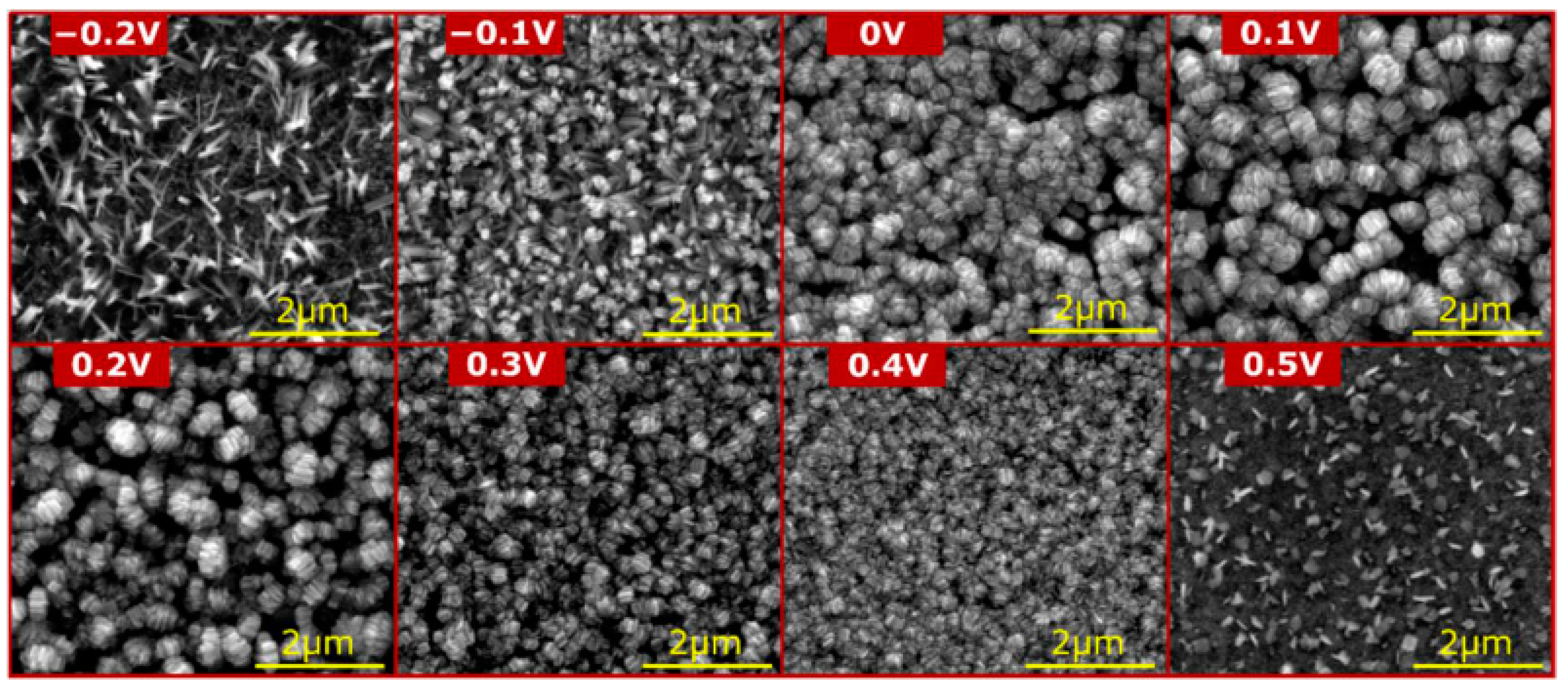
| 37% | Three-electrode system, 1.0 M NaOH, from −200 to 500 mV vs. Ag|AgCl, RT | The impact of the passivation potential on the morphology of the formed passive oxides was investigated; photodegradation of methyl orange was performed | [103] |
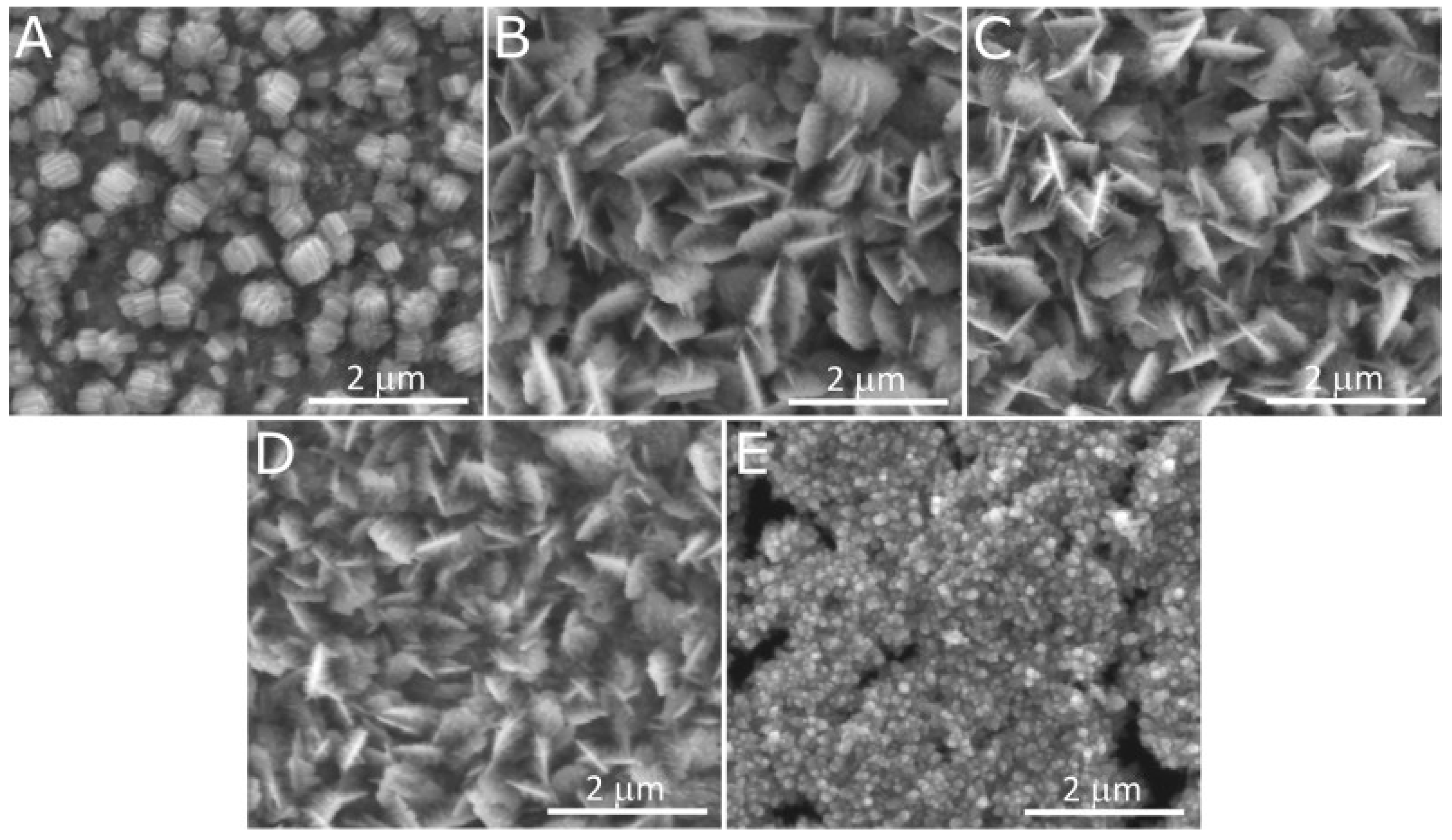
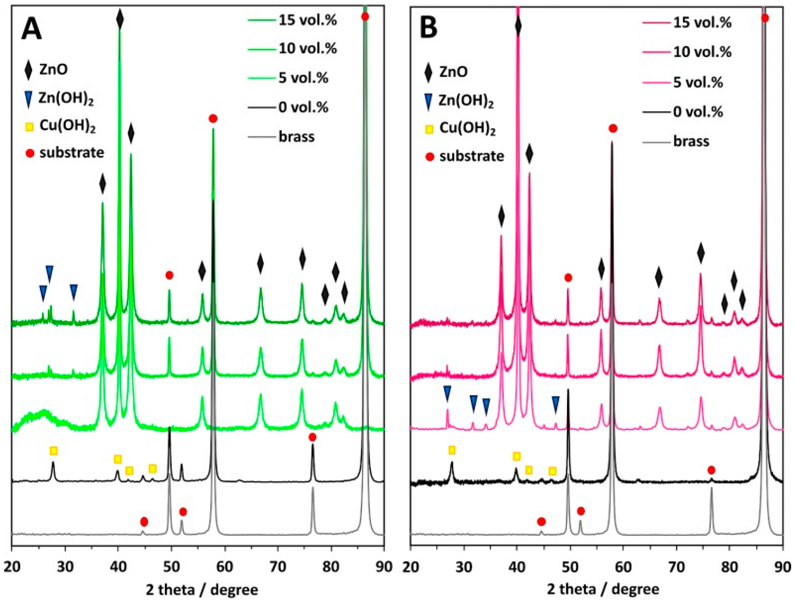
| 37% | Three-electrode system, 1.0 M NaOH, from 100 to 300 mV vs. Hg|HgO|3 M KOH, RT; from 0 to 30 vol. % of glycerol was added into electrolytes | In the study, the impact of the glycerol on the morphology and composition of the grown nanostructured passive films was investigated; the grown nanostructures were used as a cathode in the electrochemical carbon dioxide reduction reaction, and it was revealed that the best samples are the ones obtained in 1.0 M NaOH without additives | [104] |
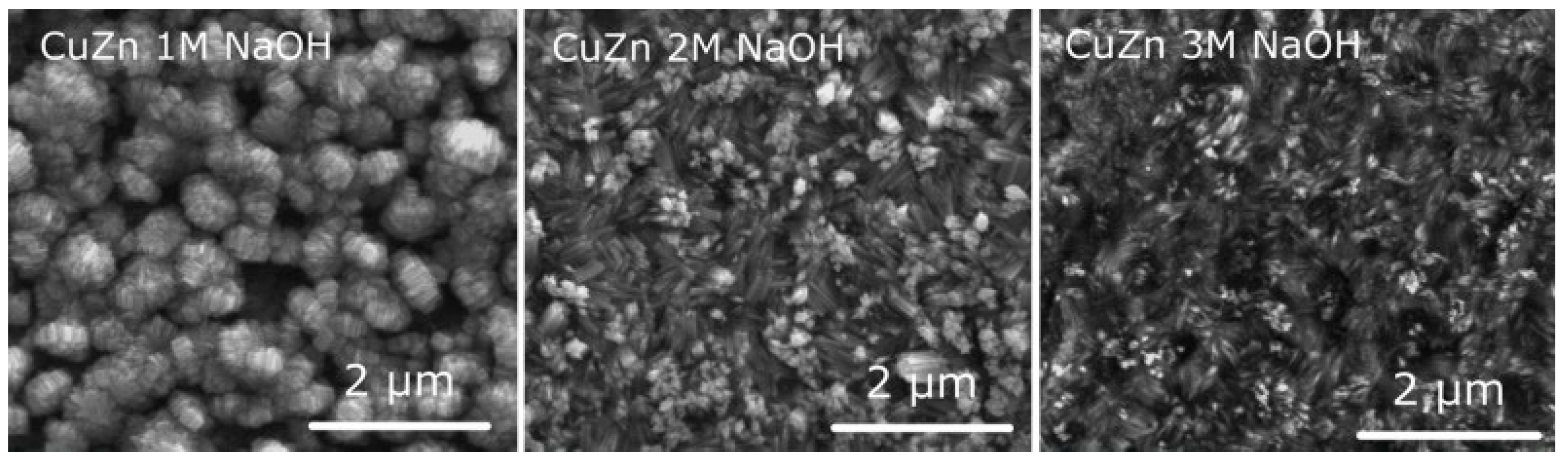
| 37% | Three-electrode system, 1.0–3.0 M NaOH, 0 or 100 mV vs. Hg|HgO|3 M KOH, RT | Cu, CuAg10, and Cu63Zn37 were oxidized using a potentiostat; the samples were examined before and after the electrochemical carbon dioxide reduction reaction to compare systematically the chemical composition and morphology before and after the reaction | [85] |
| NA; “Cu-Zn” | Two-electrode system, 1.0 M (COOH)2, 40 V, RT, 25 min | Cu-Zn anodization was used to increase the surface area of deposited NiO; developed morphology | [105] |
| 5% Zn (ASME SB36 C210) | Three-electrode system, 1.0 M KOH, −0.05, and −0.065 V vs. Hg|HgO, RT, 125 s | Depending on the applied potential, different morphologies were obtained; anodized brass lowered the onset potential for methanol electrooxidation (1.0 M KOH + 1.0 M CH3OH); based on EIS, also charge transfer resistance was low for the anodized samples | [106] |
| Synthesis Conditions | Remarks |
|---|---|
| Oxidation apparatus | Two-electrode system vs. potentiostat It was found that the ordered nanostructures were applied when the potentiostat was applied (Figure 6, Figure 8 and Figure 10) [85,103,104,106]. When a two-electrode, direct-current power supply was used, an oxide with a developed surface area was obtained, rather than the well-defined nanostructures [99,100,101,102] |
| Type of electrolyte | Electrolytes from mildly alkaline (1.0 M NaHCO3 [99]) to strongly alkaline (3 M NaOH [85]) were used; there is an individual report on brass passivation in 1.0 M (COOH)2 [105] |
| Electrolyte additives | Glycerol allows for steering the Cu:Zn ratio in the grown nanostructures and tunes the morphology [104]; NH4Cl allows the incorporation of CuCl2 in the grown oxide and the formation of a more developed surface area [101] |
Disclaimer/Publisher’s Note: The statements, opinions and data contained in all publications are solely those of the individual author(s) and contributor(s) and not of MDPI and/or the editor(s). MDPI and/or the editor(s) disclaim responsibility for any injury to people or property resulting from any ideas, methods, instructions or products referred to in the content. |
© 2025 by the authors. Licensee MDPI, Basel, Switzerland. This article is an open access article distributed under the terms and conditions of the Creative Commons Attribution (CC BY) license (https://creativecommons.org/licenses/by/4.0/).
Share and Cite
Anioł, W.J.; Dobroń, P.; Tomczyk, K.; Stępniowski, W.J. Nanostructures Formed by Brass Electrochemical Oxidation—Fabrication Strategies and Emerging Applications. Materials 2025, 18, 1728. https://doi.org/10.3390/ma18081728
Anioł WJ, Dobroń P, Tomczyk K, Stępniowski WJ. Nanostructures Formed by Brass Electrochemical Oxidation—Fabrication Strategies and Emerging Applications. Materials. 2025; 18(8):1728. https://doi.org/10.3390/ma18081728
Chicago/Turabian StyleAnioł, Wojciech Jan, Piotr Dobroń, Katarzyna Tomczyk, and Wojciech J. Stępniowski. 2025. "Nanostructures Formed by Brass Electrochemical Oxidation—Fabrication Strategies and Emerging Applications" Materials 18, no. 8: 1728. https://doi.org/10.3390/ma18081728
APA StyleAnioł, W. J., Dobroń, P., Tomczyk, K., & Stępniowski, W. J. (2025). Nanostructures Formed by Brass Electrochemical Oxidation—Fabrication Strategies and Emerging Applications. Materials, 18(8), 1728. https://doi.org/10.3390/ma18081728