
Optimization of LCD-Based 3D Printing for the Development of Clotrimazole-Coated Microneedle Systems

 , , , ,
  , ,
, ,  , ,
, , 
Abstract

1. Introduction
2. Materials and Methods
2.1. Materials
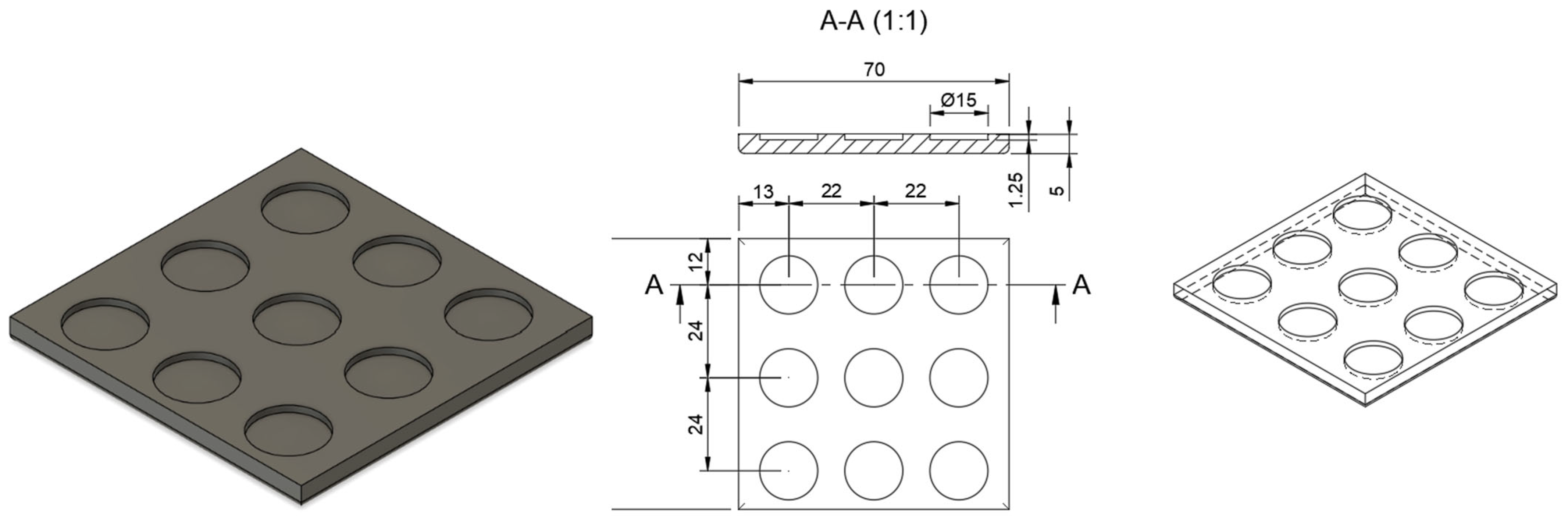
2.2. Design of Microneedle Systems
2.3. Manufacturing Process for Three-Dimensional (3D)-Printed Microneedle Systems
2.3.1. Optimizing Needle Density Within the Microneedle System
2.3.2. Optimizing Three-Dimensional (3D) Printing Parameters
2.4. Characterization of the Microneedle Systems
2.4.1. Insertion Studies
Parafilm® M Insertion
Agarose Gel Insertion
2.4.2. Mechanical Properties
2.5. Fabrication of Clotrimazole-Coated Microneedle Systems
2.5.1. Preparation of the Clotrimazole-Based Hydrogels
2.5.2. Coating Method for Microneedle Systems
2.6. Microscopic Analysis of Microneedle Systems
2.7. Pharmaceutical Evaluation of Clotrimazole (CLO)-Coated Microneedle Systems
2.7.1. High-Performance Liquid Chromatography (HPLC) Analysis
2.7.2. Drug Content Determination
2.7.3. Evaluation of In Vitro Drug Release
2.8. Antifungal Properties
2.9. Acute Toxicity
2.10. Statistical Analysis
3. Results
3.1. Optimizing the Manufacturing Process for Three-Dimensional (3D)-Printed Microneedle Systems
3.1.1. Needle Density
3.1.2. Anti-Aliasing
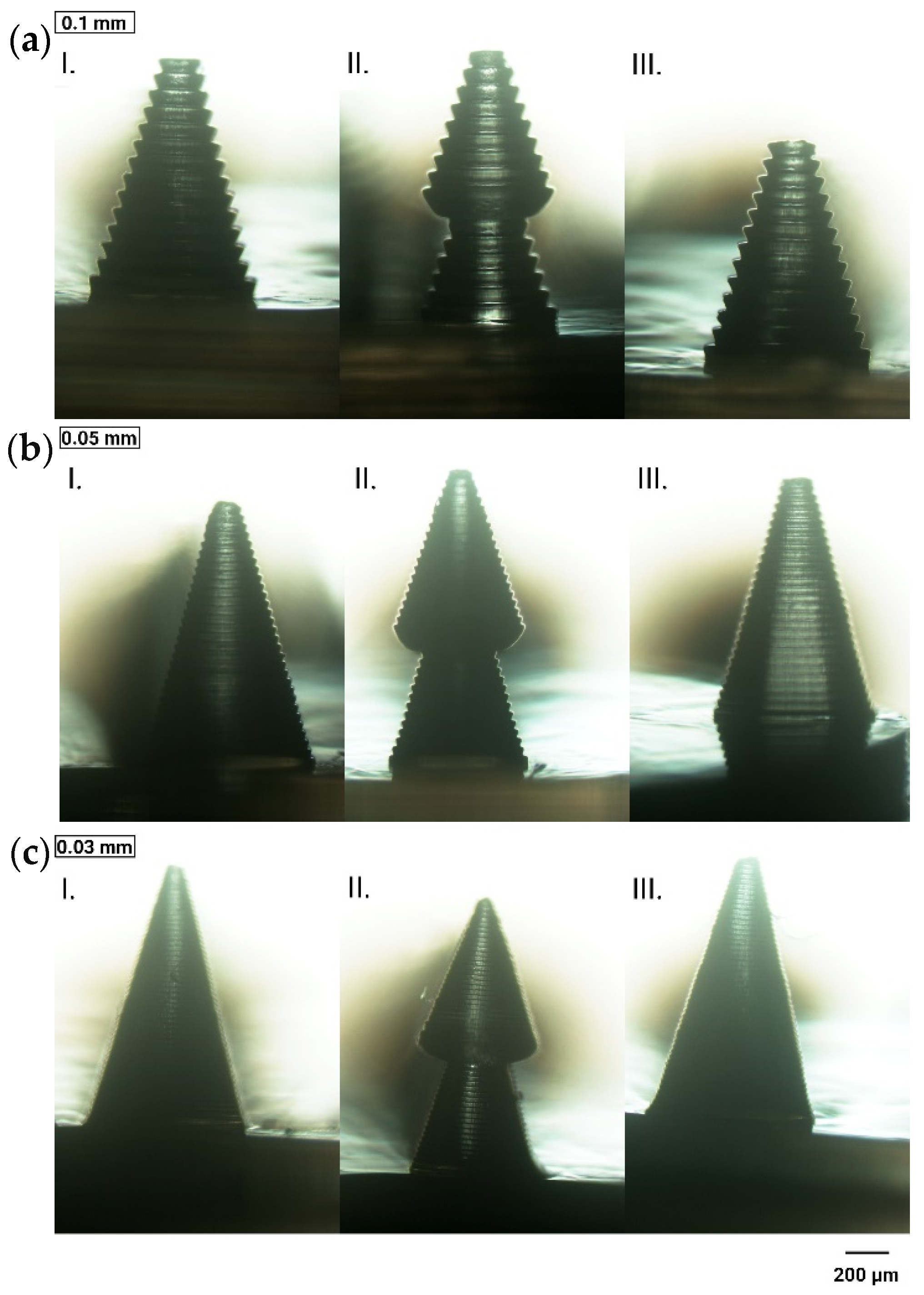
3.1.3. Layer Thickness
3.1.4. Curing Time
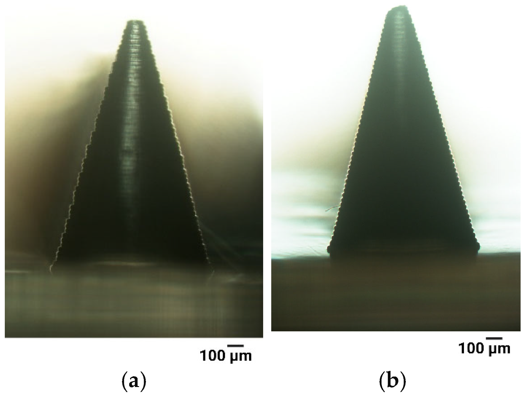
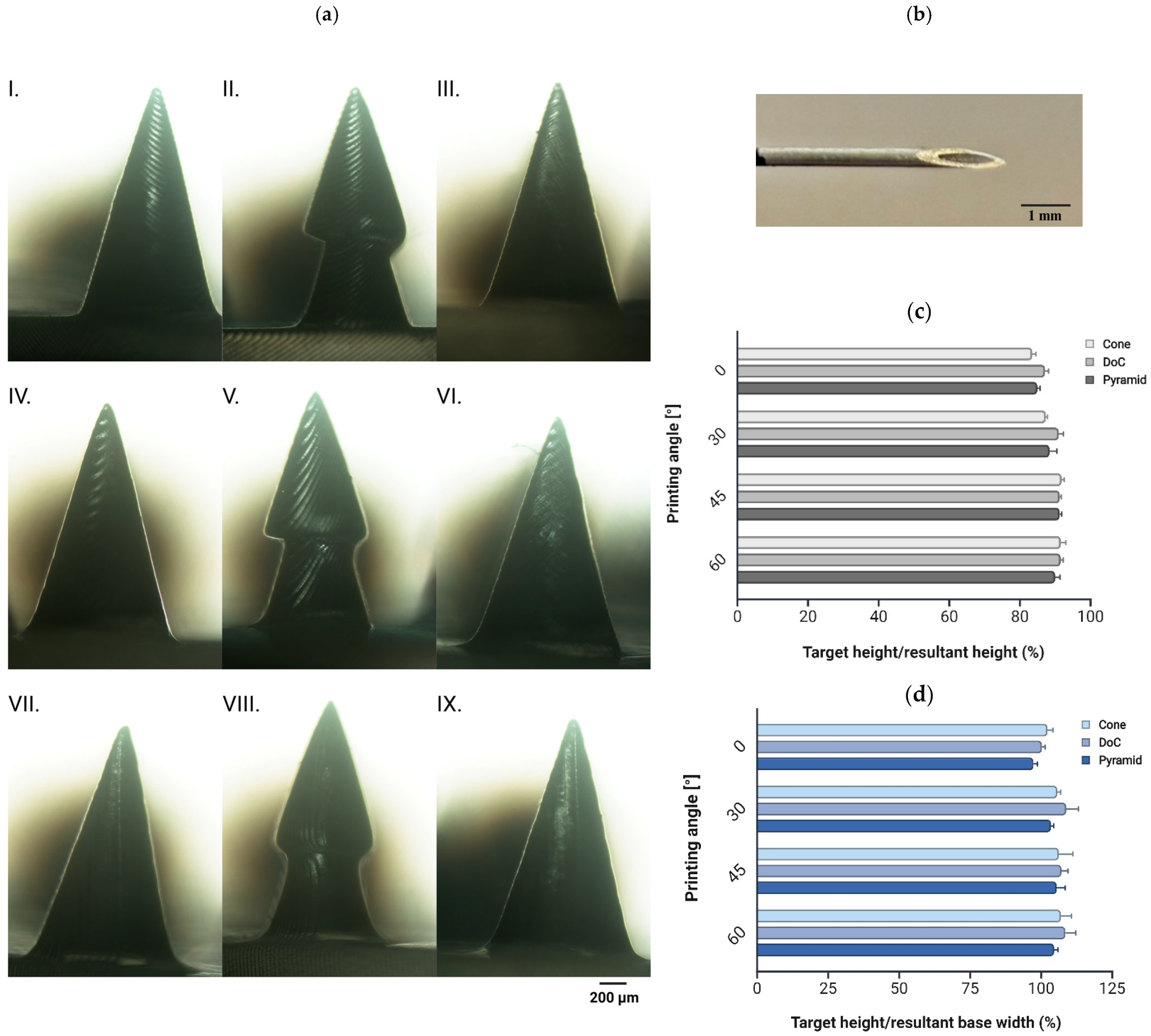
3.1.5. Printing Angle
- Shape A (cone) and shape C (pyramid): 17 microneedles per patch, 0.03 mm layer thickness, 7.5 s curing time, 45° printing angle, with anti-aliasing applied;
- Shape B (DoC): 17 microneedles per patch, 0.03 mm layer thickness, 7.5 s curing time, 60° printing angle, with anti-aliasing applied.
3.2. Characterization of the Microneedle Systems
3.2.1. Insertion Studies
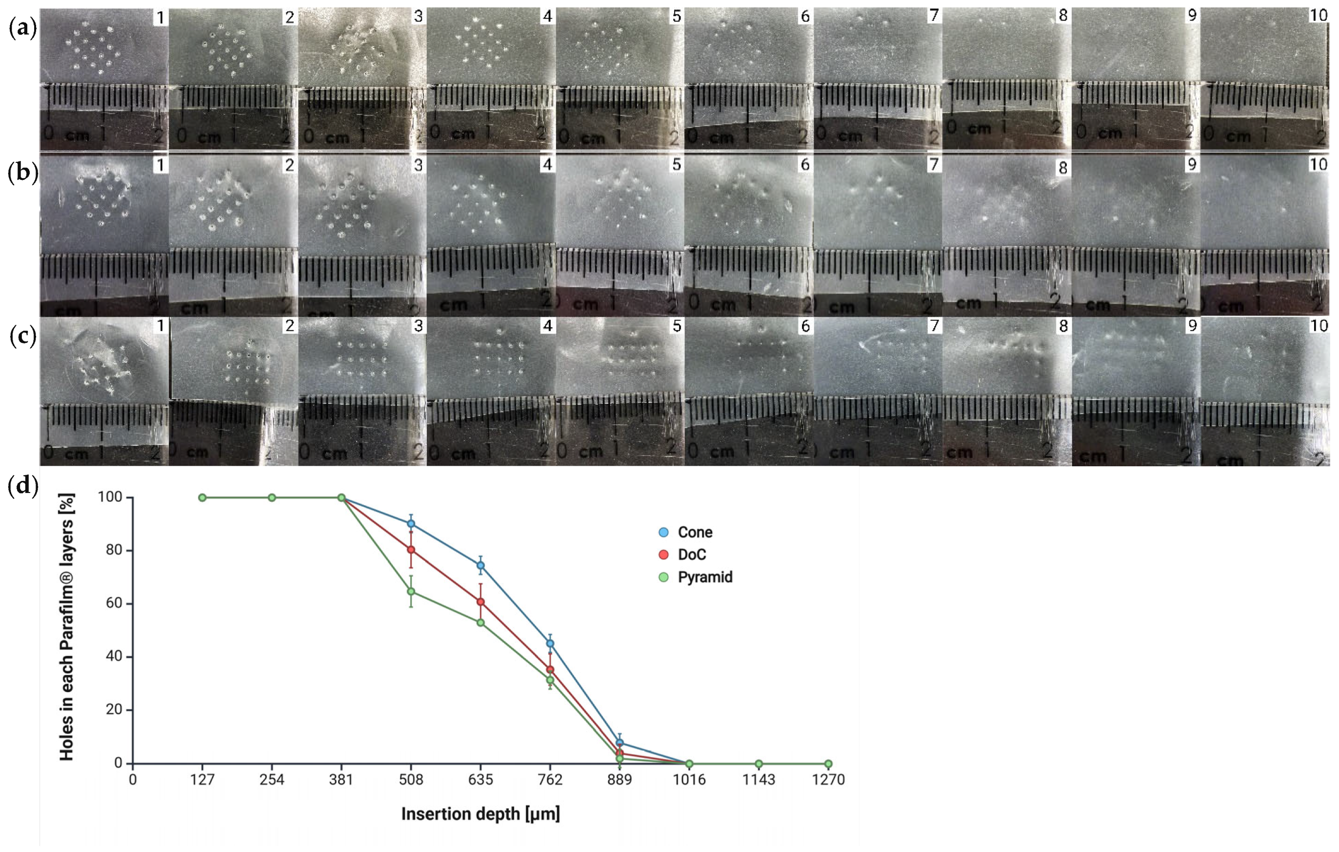
Parafilm® M Insertion
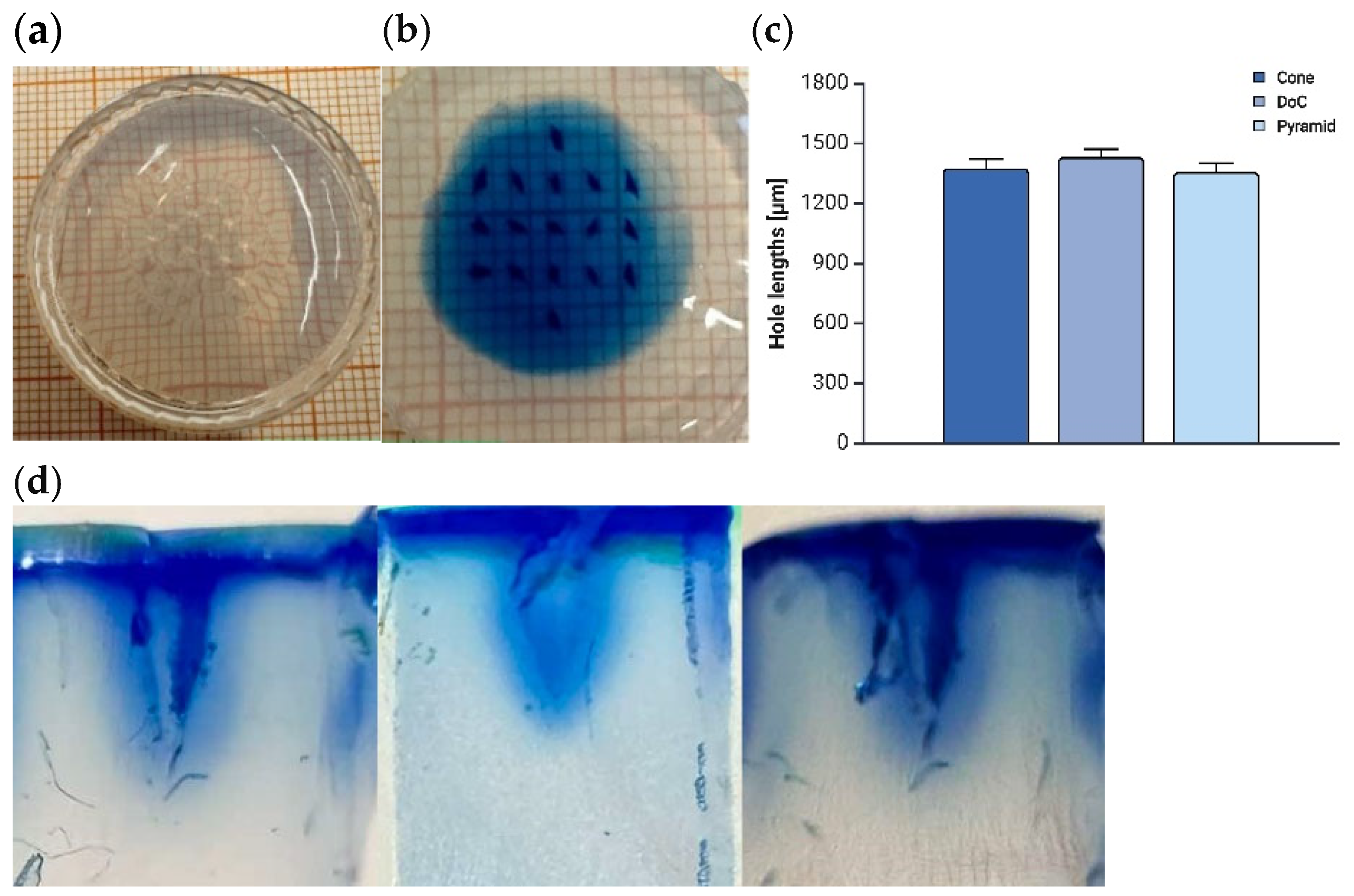
Agarose Insertion
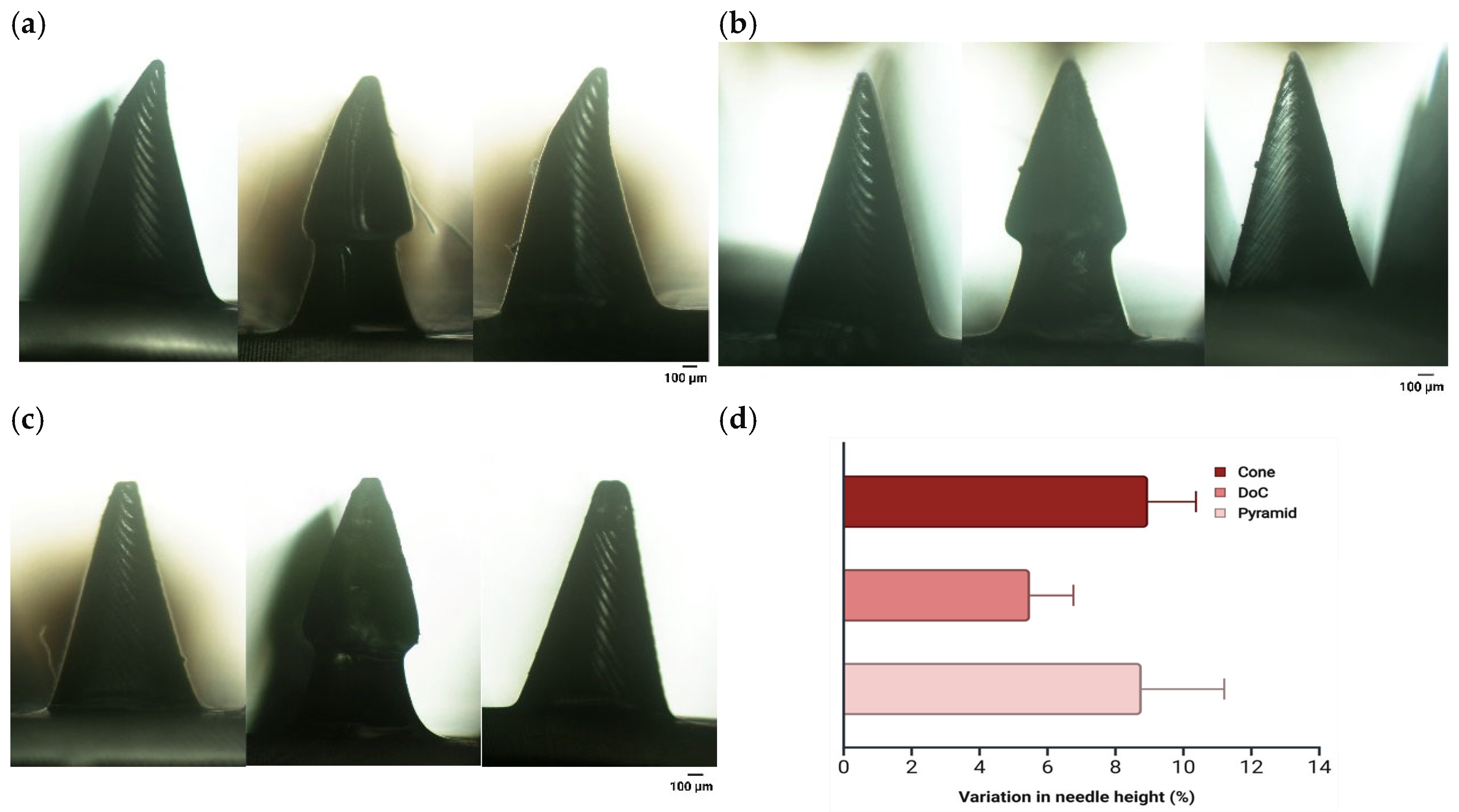
3.2.2. Mechanical Properties
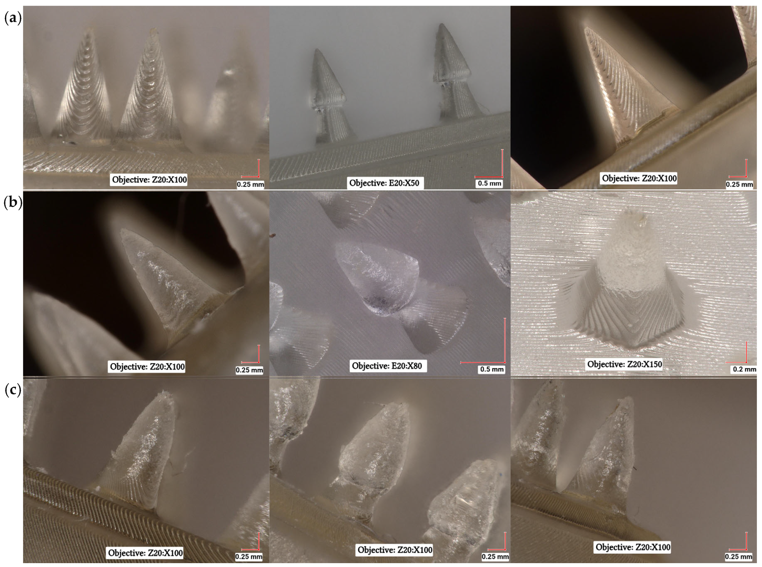
3.3. Microscopic Analysis of Microneedle Systems
3.4. Pharmaceutical Evaluation of Clotrimazole (CLO)-Coated Microneedle Systems
3.4.1. Drug Content Determination
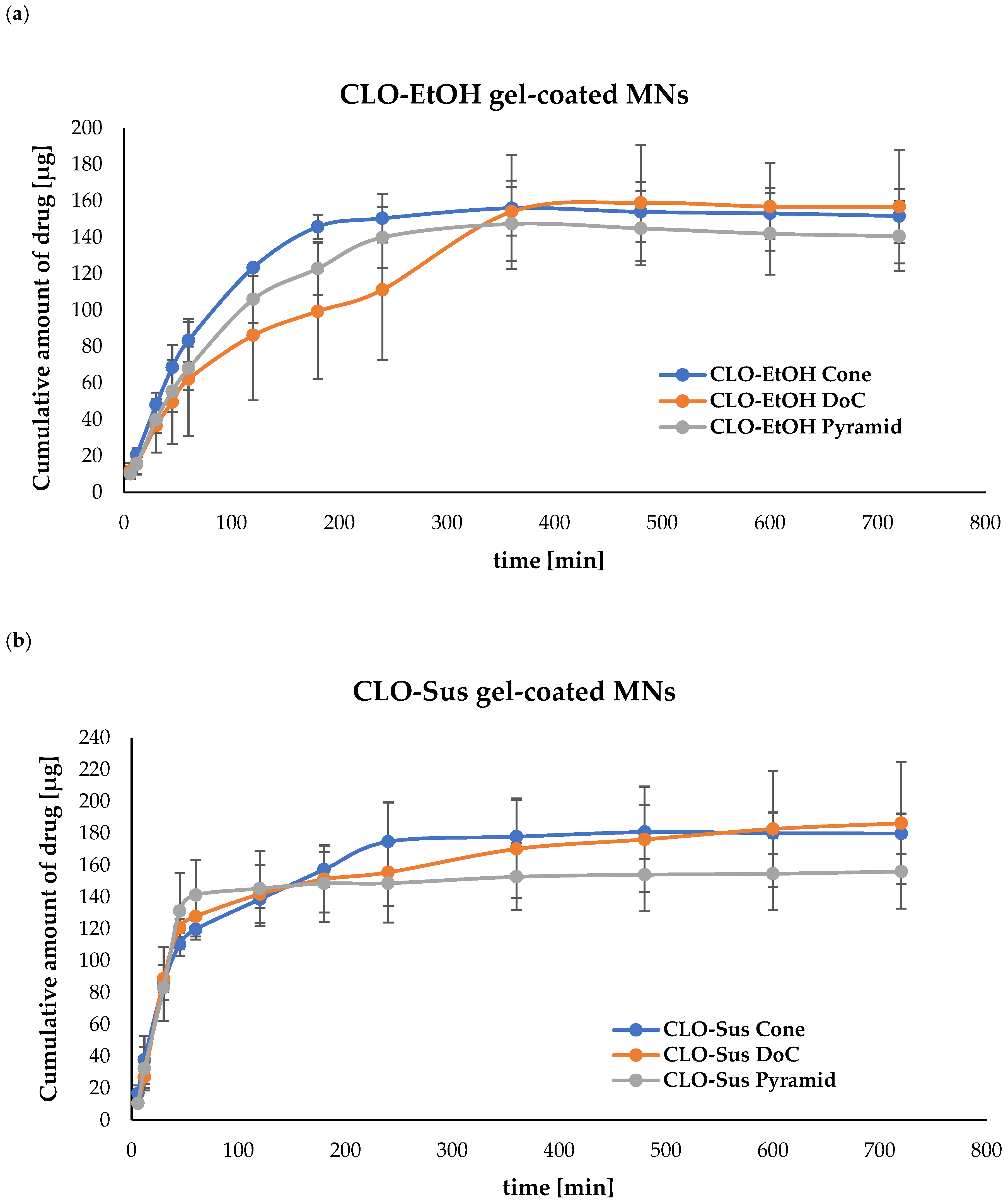
3.4.2. Evaluation of In Vitro Drug Release from Microneedle (MN) Systems
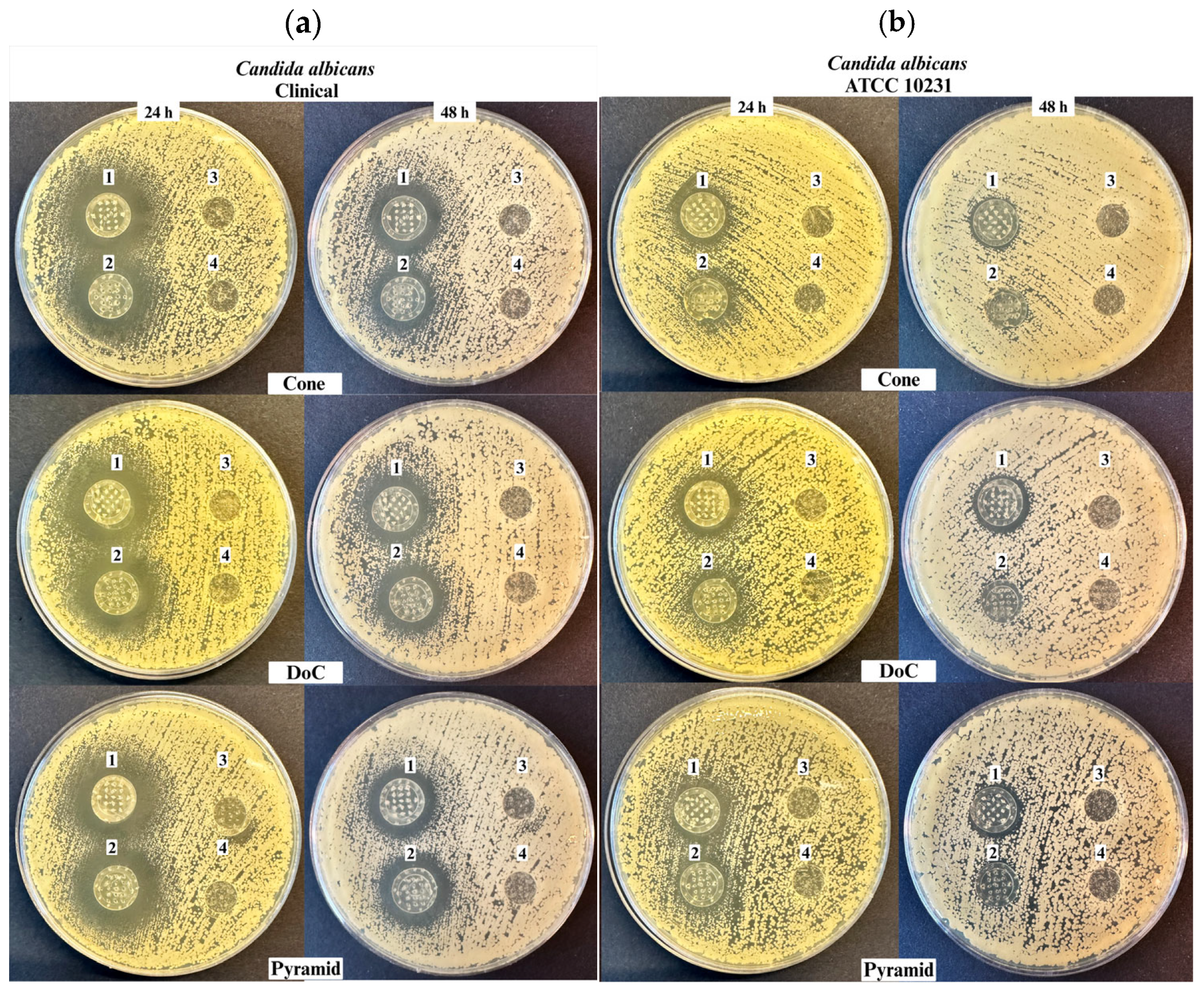
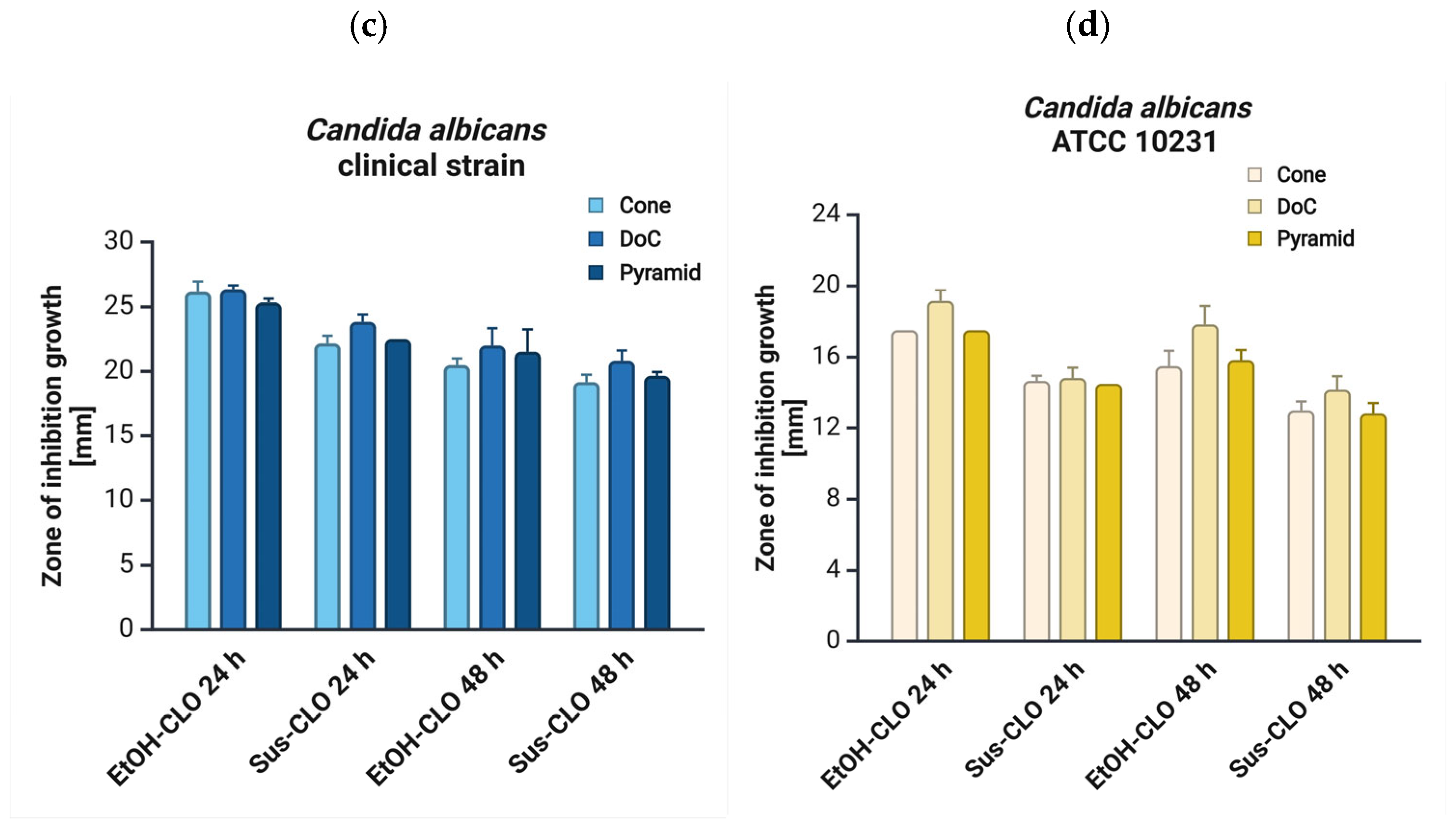
3.5. Antifungal Properties
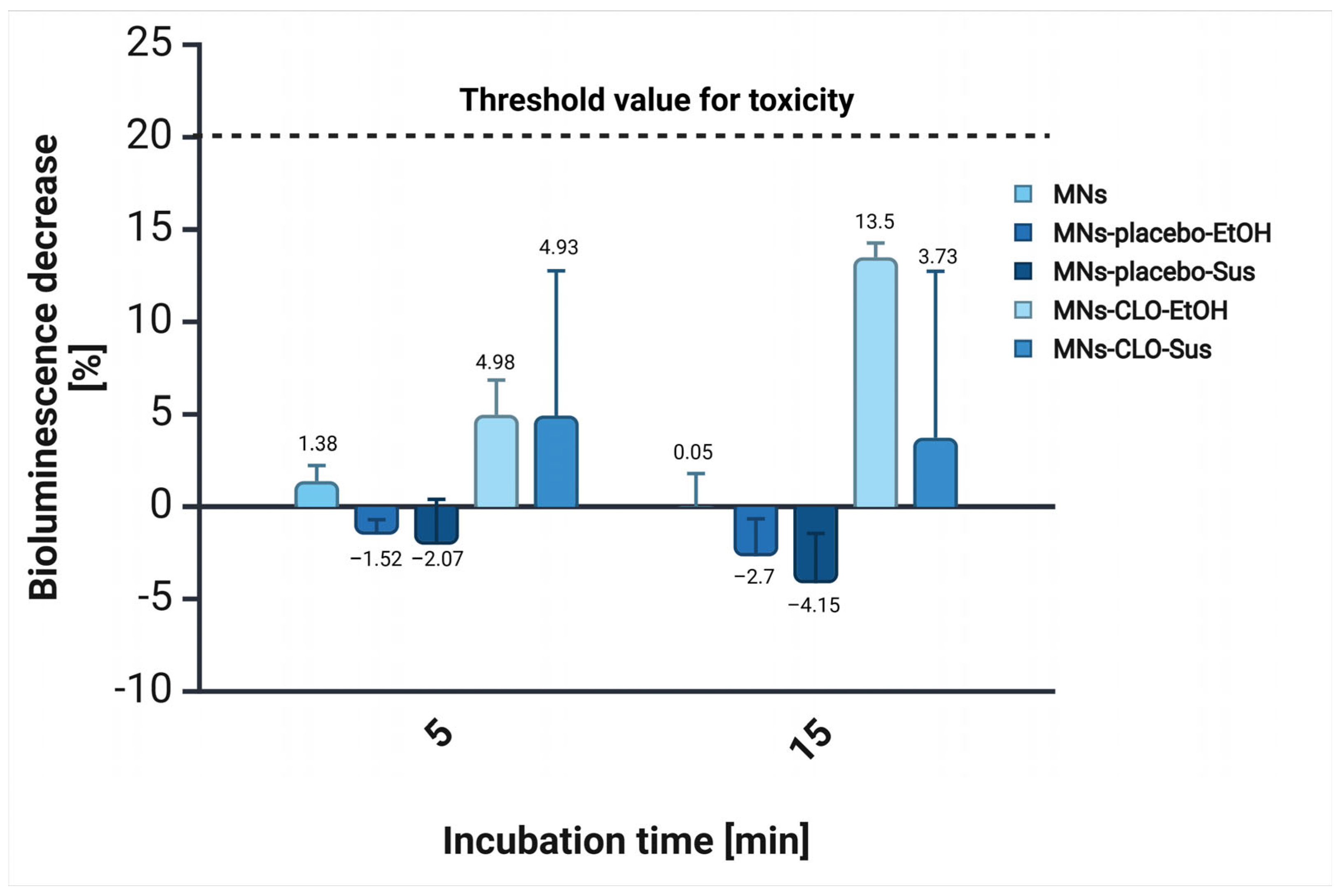
3.6. Acute Toxicity
4. Discussion
5. Conclusions
Author Contributions
Funding
Institutional Review Board Statement
Informed Consent Statement
Data Availability Statement
Acknowledgments
Conflicts of Interest
References
- Mudenda, S. Global Burden of Fungal Infections and Antifungal Resistance from 1961 to 2024: Findings and Future Implications. Pharmacol. Pharm. 2024, 15, 81–112. [Google Scholar] [CrossRef]
- Havlickova, B.; Czaika, V.A.; Friedrich, M. Epidemiological Trends in Skin Mycoses Worldwide. Mycoses 2008, 51, 2–15. [Google Scholar] [CrossRef] [PubMed]
- Kruithoff, C.; Gamal, A.; McCormick, T.S.; Ghannoum, M.A. Dermatophyte Infections Worldwide: Increase in Incidence and Associated Antifungal Resistance. Life 2023, 14, 1. [Google Scholar] [CrossRef] [PubMed]
- Haro, M.; Alemayehu, T.; Mikiru, A. Dermatophytosis and Its Risk Factors among Children Visiting Dermatology Clinic in Hawassa Sidama, Ethiopia. Sci. Rep. 2023, 13, 8630. [Google Scholar] [CrossRef]
- Shah, P.; Bhargava, S.; Chakrabarty, S.; Damodaran, R.T.; Saikia, P.K.; Shenoy, M.; Bangale, N. Rising Burden of Superficial Fungal Infections in India and the Role of Clotrimazole for Optimal Management. IP Ind. J. Clin. Exp. Dermatol. 2023, 9, 1–16. [Google Scholar] [CrossRef]
- Urban, K.; Chu, S.; Scheufele, C.; Giesey, R.L.; Mehrmal, S.; Uppal, P.; Delost, G.R. The Global, Regional, and National Burden of Fungal Skin Diseases in 195 Countries and Territories: A Cross-Sectional Analysis from the Global Burden of Disease Study 2017. JAAD Int. 2021, 2, 22–27. [Google Scholar] [CrossRef]
- Chanyachailert, P.; Leeyaphan, C.; Bunyaratavej, S. Cutaneous Fungal Infections Caused by Dermatophytes and Non-Dermatophytes: An Updated Comprehensive Review of Epidemiology, Clinical Presentations, and Diagnostic Testing. J. Fungi 2023, 9, 669. [Google Scholar] [CrossRef]
- Casadevall, A. Fungal Diseases in the 21st Century: The Near and Far Horizons. Pathog. Immunity 2018, 3, 183. [Google Scholar] [CrossRef]
- Loh, J.T.; Lam, K.-P. Fungal Infections: Immune Defense, Immunotherapies and Vaccines. Adv. Drug Deliv. Rev. 2023, 196, 114775. [Google Scholar] [CrossRef]
- Raut, A.; Huy, N.T. Rising Incidence of Mucormycosis in Patients with COVID-19: Another Challenge for India amidst the Second Wave? Lancet Respir. Med. 2021, 9, e77. [Google Scholar] [CrossRef]
- Denning, D.W. Global Incidence and Mortality of Severe Fungal Disease. Lancet Infect. Dis. 2024, 24, e428–e438. [Google Scholar] [CrossRef]
- Saadatfar, F.; Shayanfar, A.; Rahimpour, E.; Barzegar-Jalali, M.; Martinez, F.; Bolourtchian, M.; Jouyban, A. Measurement and Correlation of Clotrimazole Solubility in Ethanol + Water Mixtures at T = (293.2 to 313.2) K. J. Mol. Liq. 2018, 256, 527–532. [Google Scholar] [CrossRef]
- Blokhina, S.; Sharapova, A.; Ol’khovich, M.; Perlovich, G. Experimental Solubility of Clotrimazole and Some Thermodynamic Aspects of Dissolution in Different Solvents. Thermochim. Acta 2019, 682, 178431. [Google Scholar] [CrossRef]
- Crowley, P.D.; Gallagher, H.C. Clotrimazole as a Pharmaceutical: Past, Present and Future. J. Appl. Microbiol. 2014, 117, 611–617. [Google Scholar] [CrossRef]
- Khatter, N.J.; Khan, M.A. Clotrimazole. In StatPearls; StatPearls Publishing: Treasure Island, FL, USA, 2025. [Google Scholar]
- Waugh, C.D. Clotrimazole. In xPharm: The Comprehensive Pharmacology Reference; Elsevier: Amsterdam, The Netherlands, 2007; pp. 1–4. ISBN 978-0-08-055232-3. [Google Scholar]
- Usach, I.; Martínez-Álvarez, P.; Peris, J.-E. Topical Delivery Systems Containing Clotrimazole for the Management of Candidiasis: Effect of Different Excipients and Enhanced Antifungal Activity of Nanovesicles. Int. J. Pharm. 2023, 644, 123287. [Google Scholar] [CrossRef]
- Mijaljica, D.; Spada, F.; Harrison, I.P. Emerging Trends in the Use of Topical Antifungal-Corticosteroid Combinations. J. Fungi 2022, 8, 812. [Google Scholar] [CrossRef]
- Nikolaev, B.; Yakovleva, L.; Fedorov, V.; Li, H.; Gao, H.; Shevtsov, M. Nano- and Microemulsions in Biomedicine: From Theory to Practice. Pharmaceutics 2023, 15, 1989. [Google Scholar] [CrossRef]
- Bolla, P.K.; Meraz, C.A.; Rodriguez, V.A.; Deaguero, I.; Singh, M.; Yellepeddi, V.K.; Renukuntla, J. Clotrimazole Loaded Ufosomes for Topical Delivery: Formulation Development and In-Vitro Studies. Molecules 2019, 24, 3139. [Google Scholar] [CrossRef]
- Choudhury, Q.J.; Ambati, S.; Link, C.D.; Lin, X.; Lewis, Z.A.; Meagher, R.B. Dectin-3-targeted Antifungal Liposomes Efficiently Bind and Kill Diverse Fungal Pathogens. Mol. Microbiol. 2023, 120, 723–739. [Google Scholar] [CrossRef]
- Garg, A.K.; Maddiboyina, B.; Alqarni, M.H.S.; Alam, A.; Aldawsari, H.M.; Rawat, P.; Singh, S.; Kesharwani, P. Solubility Enhancement, Formulation Development and Antifungal Activity of Luliconazole Niosomal Gel-Based System. J. Biomater. Sci. Polym. Ed. 2021, 32, 1009–1023. [Google Scholar] [CrossRef]
- Gratieri, T.; Krawczyk-Santos, A.P.; Da Rocha, P.B.R.; Cunha–Filho, M.; Gelfuso, G.M.; Marreto, R.N.; Taveira, S.F. SLN- and NLC-Encapsulating Antifungal Agents: Skin Drug Delivery and Their Unexplored Potential for Treating Onychomycosis. Curr. Pharm. Des. 2018, 23, 6684–6695. [Google Scholar] [CrossRef]
- Godge, G.R.; Bharat, S.C.; Shaikh, A.B.; Randhawan, B.B.; Raskar, M.A.; Hiremath, S.N. Formulation Perspectives in Topical Antifungal Drug Therapy: A Review. J. Drug Deliv. Ther. 2023, 13, 110–119. [Google Scholar] [CrossRef]
- Ravani, L.; Esposito, E.; Bories, C.; Moal, V.L.-L.; Loiseau, P.M.; Djabourov, M.; Cortesi, R.; Bouchemal, K. Clotrimazole-Loaded Nanostructured Lipid Carrier Hydrogels: Thermal Analysis and in Vitro Studies. Int. J. Pharm. 2013, 454, 695–702. [Google Scholar] [CrossRef]
- Faraji Rad, Z.; Prewett, P.D.; Davies, G.J. Microneedle Patches—The Future of Drug Delivery and Vaccination? Beilstein J. Nanotechnol. 2023, 14, 494–495. [Google Scholar] [CrossRef]
- Gerstel, M.S.; Place, V.A. Drug Delivery Device. U.S. Patent No. US3964482A, 22 June 1976. Available online: https://patents.google.com/patent/US3964482A/en (accessed on 27 March 2025).
- Nayak, S.; Suryawanshi, S.; Bhaskar, V. Microneedle technology for transdermal drug delivery: Applications and combination with other enhancing techniques. J. Drug Deliv. Ther. 2016, 6, 65–83. [Google Scholar] [CrossRef]
- Mdanda, S.; Ubanako, P.; Kondiah, P.P.D.; Kumar, P.; Choonara, Y.E. Recent Advances in Microneedle Platforms for Transdermal Drug Delivery Technologies. Polymers 2021, 13, 2405. [Google Scholar] [CrossRef]
- Donnelly, R.F.; Singh, T.R.R.; Tunney, M.M.; Morrow, D.I.J.; McCarron, P.A.; O’Mahony, C.; Woolfson, A.D. Microneedle Arrays Allow Lower Microbial Penetration Than Hypodermic Needles In Vitro. Pharm. Res. 2009, 26, 2513–2522. [Google Scholar] [CrossRef]
- Coulman, S.A.; Birchall, J.C.; Alex, A.; Pearton, M.; Hofer, B.; O’Mahony, C.; Drexler, W.; Považay, B. In Vivo, In Situ Imaging of Microneedle Insertion into the Skin of Human Volunteers Using Optical Coherence Tomography. Pharm. Res. 2011, 28, 66–81. [Google Scholar] [CrossRef]
- Vora, L.K.; Moffatt, K.; Tekko, I.A.; Paredes, A.J.; Volpe-Zanutto, F.; Mishra, D.; Peng, K.; Raj Singh Thakur, R.; Donnelly, R.F. Microneedle Array Systems for Long-Acting Drug Delivery. Eur. J. Pharm. Biopharm. 2021, 159, 44–76. [Google Scholar] [CrossRef]
- Tarbox, T.N.; Watts, A.B.; Cui, Z.; Williams, R.O. An Update on Coating/Manufacturing Techniques of Microneedles. Drug Deliv. Transl. Res. 2018, 8, 1828–1843. [Google Scholar] [CrossRef]
- Shafique, H.; Karamzadeh, V.; Kim, G.; Morocz, Y.; Sohrabi-Kashani, A.; Shen, M.L.; Juncker, D. High-Resolution Low-Cost LCD 3D Printing of Microfluidics. arXiv 2024. [Google Scholar] [CrossRef]
- Loh, J.M.; Lim, Y.J.L.; Tay, J.T.; Cheng, H.M.; Tey, H.L.; Liang, K. Design and Fabrication of Customizable Microneedles Enabled by 3D Printing for Biomedical Applications. Bioact. Mater. 2024, 32, 222–241. [Google Scholar] [CrossRef]
- Pagac, M.; Hajnys, J.; Ma, Q.-P.; Jancar, L.; Jansa, J.; Stefek, P.; Mesicek, J. A Review of Vat Photopolymerization Technology: Materials, Applications, Challenges, and Future Trends of 3D Printing. Polymers 2021, 13, 598. [Google Scholar] [CrossRef]
- Iftekar, S.F.; Aabid, A.; Amir, A.; Baig, M. Advancements and Limitations in 3D Printing Materials and Technologies: A Critical Review. Polymers 2023, 15, 2519. [Google Scholar] [CrossRef]
- Fitaihi, R.; Abukhamees, S.; Chung, S.H.; Craig, D.Q.M. Optimization of Stereolithography 3D Printing of Microneedle Micro-Molds for Ocular Drug Delivery. Int. J. Pharm. 2024, 658, 124195. [Google Scholar] [CrossRef]
- Mathew, E.; Pitzanti, G.; Gomes Dos Santos, A.L.; Lamprou, D.A. Optimization of Printing Parameters for Digital Light Processing 3D Printing of Hollow Microneedle Arrays. Pharmaceutics 2021, 13, 1837. [Google Scholar] [CrossRef]
- Wichniarek, R.; Kuczko, W.; Tomczak, D.; Nowicka, A.; Wojtyłko, M.; Froelich, A.; Osmałek, T. Geometrical Accuracy and Strength of Micro-Needles Made of Polylactide by Fused Filament Fabrication Method. Adv. Sci. Technol. Res. J. 2023, 17, 116–126. [Google Scholar] [CrossRef]
- Bunea, A.-I.; Del Castillo Iniesta, N.; Droumpali, A.; Wetzel, A.E.; Engay, E.; Taboryski, R. Micro 3D Printing by Two-Photon Polymerization: Configurations and Parameters for the Nanoscribe System. Micro 2021, 1, 164–180. [Google Scholar] [CrossRef]
- Gittard, S.D.; Ovsianikov, A.; Chichkov, B.N.; Doraiswamy, A.; Narayan, R.J. Two-Photon Polymerization of Microneedles for Transdermal Drug Delivery. Expert Opin. Drug Deliv. 2010, 7, 513–533. [Google Scholar] [CrossRef]
- Johnson, A.R.; Procopio, A.T. Low Cost Additive Manufacturing of Microneedle Masters. 3D Print. Med. 2019, 5, 2. [Google Scholar] [CrossRef]
- Lo Giudice, A.; Ronsivalle, V.; Rustico, L.; Aboulazm, K.; Isola, G.; Palazzo, G. Evaluation of the Accuracy of Orthodontic Models Prototyped with Entry-Level LCD-Based 3D Printers: A Study Using Surface-Based Superimposition and Deviation Analysis. Clin. Oral Investig. 2022, 26, 303–312. [Google Scholar] [CrossRef]
- Tisato, S.; Vera, G.; Mani, A.; Chase, T.; Helmer, D. An Easy-to-Build, Accessible Volumetric 3D Printer Based on a Liquid Crystal Display for Rapid Resin Development. Addit. Manuf. 2024, 87, 104232. [Google Scholar] [CrossRef]
- Roohani, I.; Entezari, A.; Zreiqat, H. Liquid Crystal Display Technique (LCD) for High Resolution 3D Printing of Triply Periodic Minimal Surface Lattices Bioceramics. Addit. Manuf. 2023, 74, 103720. [Google Scholar] [CrossRef]
- Wang, Z.; Martin, N.; Hini, D.; Mills, B.; Kim, K. Rapid Fabrication of Multilayer Microfluidic Devices Using the Liquid Crystal Display-Based Stereolithography 3D Printing System. 3D Print. Addit. Manuf. 2017, 4, 156–164. [Google Scholar] [CrossRef]
- Chanabodeechalermrung, B.; Chaiwarit, T.; Chaichit, S.; Udomsom, S.; Baipaywad, P.; Worajittiphon, P.; Jantrawut, P. HPMC/PVP K90 Dissolving Microneedles Fabricated from 3D-Printed Master Molds: Impact on Microneedle Morphology, Mechanical Strength, and Topical Dissolving Property. Polymers 2024, 16, 452. [Google Scholar] [CrossRef]
- Quan, H.; Zhang, T.; Xu, H.; Luo, S.; Nie, J.; Zhu, X. Photo-Curing 3D Printing Technique and Its Challenges. Bioact. Mater. 2020, 5, 110–115. [Google Scholar] [CrossRef]
- Subirada, F.; Paoli, R.; Sierra-Agudelo, J.; Lagunas, A.; Rodriguez-Trujillo, R.; Samitier, J. Development of a Custom-Made 3D Printing Protocol with Commercial Resins for Manufacturing Microfluidic Devices. Polymers 2022, 14, 2955. [Google Scholar] [CrossRef]
- Barcena, A.J.R.; Ravi, P.; Kundu, S.; Tappa, K. Emerging Biomedical and Clinical Applications of 3D-Printed Poly(Lactic Acid)-Based Devices and Delivery Systems. Bioengineering 2024, 11, 705. [Google Scholar] [CrossRef]
- Kantaros, A.; Ganetsos, T.; Petrescu, F.I.T.; Alysandratou, E. Bioprinting and Intellectual Property: Challenges, Opportunities, and the Road Ahead. Bioengineering 2025, 12, 76. [Google Scholar] [CrossRef]
- Alghauli, M.A.; Aljohani, R.; Aljohani, W.; Almutairi, S.; Alqutaibi, A.Y. Evolution of Medical 3D Printing, Printable Biomaterials, Prosthetic and Regenerative Dental Applications. Bioprinting 2025, 46, e00395. [Google Scholar] [CrossRef]
- Kantaros, A. 3D Printing in Regenerative Medicine: Technologies and Resources Utilized. Int. J. Mol. Sci. 2022, 23, 14621. [Google Scholar] [CrossRef]
- El Aita, I.; Ponsar, H.; Quodbach, J. A Critical Review on 3D-Printed Dosage Forms. Curr. Pharm. Des. 2019, 24, 4957–4978. [Google Scholar] [CrossRef]
- Seniutinas, G.; Weber, A.; Padeste, C.; Sakellari, I.; Farsari, M.; David, C. Beyond 100 Nm Resolution in 3D Laser Lithography—Post Processing Solutions. Microelectron. Eng. 2018, 191, 25–31. [Google Scholar] [CrossRef]
- Anjani, Q.K.; Nainggolan, A.D.C.; Li, H.; Miatmoko, A.; Larrañeta, E.; Donnelly, R.F. Parafilm® M and Strat-M® as Skin Simulants in in Vitro Permeation of Dissolving Microarray Patches Loaded with Proteins. Int. J. Pharm. 2024, 655, 124071. [Google Scholar] [CrossRef]
- Larrañeta, E.; Moore, J.; Vicente-Pérez, E.M.; González-Vázquez, P.; Lutton, R.; Woolfson, A.D.; Donnelly, R.F. A Proposed Model Membrane and Test Method for Microneedle Insertion Studies. Int. J. Pharm. 2014, 472, 65–73. [Google Scholar] [CrossRef]
- Davis, S.P.; Landis, B.J.; Adams, Z.H.; Allen, M.G.; Prausnitz, M.R. Insertion of Microneedles into Skin: Measurement and Prediction of Insertion Force and Needle Fracture Force. J. Biomech. 2004, 37, 1155–1163. [Google Scholar] [CrossRef]
- Jadach, B.; Nowak, A.; Długaszewska, J.; Kordyl, O.; Budnik, I.; Osmałek, T. Coated Microneedle System for Delivery of Clotrimazole in Deep-Skin Mycoses. Gels 2024, 10, 264. [Google Scholar] [CrossRef]
- Wojtyłko, M.; Nowicka, A.B.; Froelich, A.; Szybowicz, M.; Banaszek, T.; Tomczak, D.; Kuczko, W.; Wichniarek, R.; Budnik, I.; Jadach, B.; et al. Characteristics of Hydrogels as a Coating for Microneedle Transdermal Delivery Systems with Agomelatine. Molecules 2025, 30, 322. [Google Scholar] [CrossRef]
- Ingrole, R.S.J.; Gill, H.S. Microneedle Coating Methods: A Review with a Perspective. J. Pharmacol. Exp. Ther. 2019, 370, 555–569. [Google Scholar] [CrossRef]
- Vilimi, Z.; Király, M.; Barna, Á.T.; Pápay, Z.E.; Budai, L.; Ludányi, K.; Kállai-Szabó, N.; Antal, I. Formulation of Emulgels Containing Clotrimazole for the Treatment of Vaginal Candidiasis. Gels 2024, 10, 730. [Google Scholar] [CrossRef]
- Alves, T.; Arranca, D.; Martins, A.; Ribeiro, H.; Raposo, S.; Marto, J. Complying with the Guideline for Quality and Equivalence for Topical Semisolid Products: The Case of Clotrimazole Cream. Pharmaceutics 2021, 13, 555. [Google Scholar] [CrossRef]
- Wellington, H.; Rath, S.; Kanfer, I. A Comprehensively Validated IVRT Method Reliably Discriminates Sameness and Differences between Several Topical Clotrimazole Creams. Eur. J. Pharm. Sci. 2024, 192, 106649. [Google Scholar] [CrossRef]
- Microbics, M. Microtox Manual—A Toxicity Handbook; Microbics Corporation Inc.: Carlsbad, CA, USA, 1992; Volume I–IV. [Google Scholar]
- Williams, C.F.; Geroni, G.M.; Lloyd, D.; Choi, H.; Clark, N.; Pirog, A.; Lees, J.; Porch, A. Bioluminescence of Vibrio Fischeri: Bacteria Respond Quickly and Sensitively to Pulsed Microwave Electric (but Not Magnetic) Fields. J. Biomed. Opt. 2019, 24, 051412. [Google Scholar] [CrossRef]
- Song, H.-C.; Ray, N.; Sokolov, D.; Lefebvre, S. Anti-Aliasing for Fused Filament Deposition. Comput.-Aided Des. 2017, 89, 25–34. [Google Scholar] [CrossRef]
- Bonada, J.; Muguruza, A.; Fernández-Francos, X.; Ramis, X. Influence of Exposure Time on Mechanical Properties and Photocuring Conversion Ratios for Photosensitive Materials Used in Additive Manufacturing. Procedia Manuf. 2017, 13, 762–769. [Google Scholar] [CrossRef]
- Conforti, F.; Ioele, G.; Statti, G.A.; Marrelli, M.; Ragno, G.; Menichini, F. Antiproliferative Activity against Human Tumor Cell Lines and Toxicity Test on Mediterranean Dietary Plants. Food Chem. Toxicol. 2008, 46, 3325–3332. [Google Scholar] [CrossRef]
- Drzymała, J.; Kalka, J. Elimination of the Hormesis Phenomenon by the Use of Synthetic Sea Water in a Toxicity Test towards Aliivibrio Fischeri. Chemosphere 2020, 248, 126085. [Google Scholar]
- Reynoso, M.; Chang, A.-Y.; Wu, Y.; Murray, R.; Suresh, S.; Dugas, Y.; Wang, J.; Arroyo-Currás, N. 3D-Printed, Aptamer-Based Microneedle Sensor Arrays Using Magnetic Placement on Live Rats for Pharmacokinetic Measurements in Interstitial Fluid. Biosens. Bioelectron. 2024, 244, 115802. [Google Scholar] [CrossRef]
- Makvandi, P.; Kirkby, M.; Hutton, A.R.J.; Shabani, M.; Yiu, C.K.Y.; Baghbantaraghdari, Z.; Jamaledin, R.; Carlotti, M.; Mazzolai, B.; Mattoli, V.; et al. Engineering Microneedle Patches for Improved Penetration: Analysis, Skin Models and Factors Affecting Needle Insertion. Nanomicro Lett. 2021, 13, 93. [Google Scholar] [CrossRef]
- Lhernould, M.S.; Gobillon, C.; Lambert, P. Microneedle Array Penetration Tests: Understanding the “bed of Nails’’ Phenomenon. ONdrugDelivery 2013, 40, 29–32. [Google Scholar]
- Yan, G.; Warner, K.S.; Zhang, J.; Sharma, S.; Gale, B.K. Evaluation Needle Length and Density of Microneedle Arrays in the Pretreatment of Skin for Transdermal Drug Delivery. Int. J. Pharm. 2010, 391, 7–12. [Google Scholar] [CrossRef] [PubMed]
- Hassanpour, M.; Narongdej, P.; Alterman, N.; Moghtadernejad, S.; Barjasteh, E. Effects of Post-Processing Parameters on 3D-Printed Dental Appliances: A Review. Polymers 2024, 16, 2795. [Google Scholar] [CrossRef] [PubMed]
- Tangpothitham, S.; Pongprueksa, P.; Inokoshi, M.; Mitrirattanakul, S. Effect of Post-Polymerization with Autoclaving Treatment on Monomer Elution and Mechanical Properties of 3D-Printing Acrylic Resin for Splint Fabrication. J. Mech. Behav. Biomed. Mater. 2022, 126, 105015. [Google Scholar] [CrossRef]
- Odabasi, D.; Guler, C.; Kucukaslan, D. Evaluation of the Amount of Residual Monomer Released from Different Flowable Composite Resins. BMC Oral Health 2024, 24, 244. [Google Scholar] [CrossRef]
- Petrochenko, P.E.; Torgersen, J.; Gruber, P.; Hicks, L.A.; Zheng, J.; Kumar, G.; Narayan, R.J.; Goering, P.L.; Liska, R.; Stampfl, J.; et al. Laser 3D Printing with Sub-Microscale Resolution of Porous Elastomeric Scaffolds for Supporting Human Bone Stem Cells. Adv. Healthc. Mater. 2015, 4, 739–747. [Google Scholar] [CrossRef]
- Shan, Y.; Krishnakumar, A.; Qin, Z.; Mao, H. Reducing Lateral Stair-Stepping Defects in Liquid Crystal Display-Based Vat Photopolymerization by Defocusing the Image Pattern. Addit. Manuf. 2022, 52, 102653. [Google Scholar] [CrossRef]
- Chanabodeechalermrung, B.; Chaiwarit, T.; Udomsom, S.; Rachtanapun, P.; Piboon, P.; Jantrawut, P. Determination of Vat-Photopolymerization Parameters for Microneedles Fabrication and Characterization of HPMC/PVP K90 Dissolving Microneedles Utilizing 3D-Printed Mold. Sci. Rep. 2024, 14, 16174. [Google Scholar] [CrossRef]
- Krieger, K.J.; Bertollo, N.; Dangol, M.; Sheridan, J.T.; Lowery, M.M.; O’Cearbhaill, E.D. Simple and Customizable Method for Fabrication of High-Aspect Ratio Microneedle Molds Using Low-Cost 3D Printing. Microsyst. Nanoeng. 2019, 5, 42. [Google Scholar] [CrossRef]
- Paral, S.K.; Lin, D.-Z.; Cheng, Y.-L.; Lin, S.-C.; Jeng, J.-Y. A Review of Critical Issues in High-Speed Vat Photopolymerization. Polymers 2023, 15, 2716. [Google Scholar] [CrossRef]
- Mutlu, M.E.; Akdag, Z.; Pilavci, E.; Ulag, S.; Daglilar, S.; Gunduz, O. Production of Microneedle Patches Coated with Polyvinyl-Alcohol/Sucrose/Gentamicin Sulfate for Skin Treatment. Mater. Lett. 2025, 378, 137557. [Google Scholar] [CrossRef]
- Lopez-Ramirez, M.A.; Soto, F.; Wang, C.; Rueda, R.; Shukla, S.; Silva-Lopez, C.; Kupor, D.; McBride, D.A.; Pokorski, J.K.; Nourhani, A.; et al. Built-In Active Microneedle Patch with Enhanced Autonomous Drug Delivery. Adv. Mater. 2020, 32, 1905740. [Google Scholar] [CrossRef]
- Aldawood, F.K.; Parupelli, S.K.; Andar, A.; Desai, S. 3D Printing of Biodegradable Polymeric Microneedles for Transdermal Drug Delivery Applications. Pharmaceutics 2024, 16, 237. [Google Scholar] [CrossRef] [PubMed]
- Vinayakumar, K.B.; Silva, M.D.; Martins, A.; Mundy, S.; González-Losada, P.; Sillankorva, S. Levofloxacin-Loaded Microneedles Produced Using 3D-Printed Molds for Klebsiella pneumoniae Biofilm Control. Adv. Ther. 2023, 6, 2200320. [Google Scholar] [CrossRef]
- Choo, S.; Jin, S.; Jung, J. Fabricating High-Resolution and High-Dimensional Microneedle Mold through the Resolution Improvement of Stereolithography 3D Printing. Pharmaceutics 2022, 14, 766. [Google Scholar] [CrossRef]
- Jeong, J.; Park, J.; Lee, S. 3D Printing Fabrication Process for Fine Control of Microneedle Shape. Micro Nano Syst. Lett. 2023, 11, 1. [Google Scholar] [CrossRef]
- Ziesmer, J.; Sondén, I.; Venckute Larsson, J.; Merkl, P.; Sotiriou, G.A. Customizable Fabrication of Photothermal Microneedles with Plasmonic Nanoparticles Using Low-Cost Stereolithography Three-Dimensional Printing. ACS Appl. Bio Mater. 2024, 7, 4533–4541. [Google Scholar] [CrossRef]
- Römgens, A.M.; Bader, D.L.; Bouwstra, J.A.; Baaijens, F.P.T.; Oomens, C.W.J. Monitoring the Penetration Process of Single Microneedles with Varying Tip Diameters. J. Mech. Behav. Biomed. Mater. 2014, 40, 397–405. [Google Scholar] [CrossRef]
- Zhang, D.; Das, D.B.; Rielly, C.D. Microneedle Assisted Micro-Particle Delivery from Gene Guns: Experiments Using Skin-Mimicking Agarose Gel. J. Pharm. Sci. 2014, 103, 613–627. [Google Scholar] [CrossRef]
- Lintzeri, D.A.; Karimian, N.; Blume-Peytavi, U.; Kottner, J. Epidermal Thickness in Healthy Humans: A Systematic Review and Meta-analysis. Acad. Dermatol. Venereol. 2022, 36, 1191–1200. [Google Scholar] [CrossRef]
- Czekalla, C.; Schönborn, K.H.; Lademann, J.; Meinke, M.C. Noninvasive Determination of Epidermal and Stratum Corneum Thickness in Vivo Using Two-Photon Microscopy and Optical Coherence Tomography: Impact of Body Area, Age, and Gender. Skin. Pharmacol. Physiol. 2019, 32, 142–150. [Google Scholar] [CrossRef]
- Luo, R.; Xu, H.; Lin, Q.; Chi, J.; Liu, T.; Jin, B.; Ou, J.; Xu, Z.; Peng, T.; Quan, G.; et al. Emerging Trends in Dissolving-Microneedle Technology for Antimicrobial Skin-Infection Therapies. Pharmaceutics 2024, 16, 1188. [Google Scholar] [CrossRef] [PubMed]
- Permana, A.D.; Paredes, A.J.; Volpe-Zanutto, F.; Anjani, Q.K.; Utomo, E.; Donnelly, R.F. Dissolving Microneedle-Mediated Dermal Delivery of Itraconazole Nanocrystals for Improved Treatment of Cutaneous Candidiasis. Eur. J. Pharm. Biopharm. 2020, 154, 50–61. [Google Scholar] [CrossRef] [PubMed]
- Zarei Chamgordani, N.; Asiaei, S.; Ghorbani-Bidkorpeh, F.; Babaee Foroutan, M.; Dahmardehei, M.; Moghimi, H.R. A Long-Lasting Triamcinolone-Loaded Microneedle Patch for Prolonged Dermal Delivery. Iran. J. Pharm. Res. 2024, 23, e138857. [Google Scholar] [CrossRef] [PubMed]
- Rojekar, S.; Vora, L.K.; Tekko, I.A.; Volpe-Zanutto, F.; McCarthy, H.O.; Vavia, P.R.; Donnelly, R.F. Etravirine-Loaded Dissolving Microneedle Arrays for Long-Acting Delivery. Eur. J. Pharm. Biopharm. 2021, 165, 41–51. [Google Scholar] [CrossRef]
- Abubaker, S.S.; Zhang, Y. Optimization Design and Fabrication of Polymer Micro Needle by Hot Embossing Method. Int. J. Precis. Eng. Manuf. 2019, 20, 631–640. [Google Scholar] [CrossRef]
- Butt, M.A. Thin-Film Coating Methods: A Successful Marriage of High-Quality and Cost-Effectiveness—A Brief Exploration. Coatings 2022, 12, 1115. [Google Scholar] [CrossRef]
- Zhang, Y.; Brown, K.; Siebenaler, K.; Determan, A.; Dohmeier, D.; Hansen, K. Development of Lidocaine-Coated Microneedle Product for Rapid, Safe, and Prolonged Local Analgesic Action. Pharm. Res. 2012, 29, 170–177. [Google Scholar] [CrossRef]
- Chen, Y.; Chen, B.Z.; Wang, Q.L.; Jin, X.; Guo, X.D. Fabrication of Coated Polymer Microneedles for Transdermal Drug Delivery. J. Control Release 2017, 265, 14–21. [Google Scholar] [CrossRef]
- Huang, X.; Brazel, C.S. On the Importance and Mechanisms of Burst Release in Matrix-Controlled Drug Delivery Systems. J. Control Release 2001, 73, 121–136. [Google Scholar] [CrossRef]
- Yoo, J.; Won, Y.-Y. Phenomenology of the Initial Burst Release of Drugs from PLGA Microparticles. ACS Biomater. Sci. Eng. 2020, 6, 6053–6062. [Google Scholar] [CrossRef]
- Catellani, P.; Colombo, P.; Vitali, T.; Caramella, C. Modified Release Tablet Formulation. Polym. Med. 1988, 3, 169–174. [Google Scholar]
- Kvamme, B. Small Alcohols as Surfactants and Hydrate Promotors. Fluids 2021, 6, 345. [Google Scholar] [CrossRef]
- Horita, D.; Todo, H.; Sugibayashi, K. Effect of Ethanol Pretreatment on Skin Permeation of Drugs. Biol. Pharm. Bull. 2012, 35, 1343–1348. [Google Scholar] [CrossRef] [PubMed]
- Larrañeta, E.; Stewart, S.; Fallows, S.J.; Birkhäuer, L.L.; McCrudden, M.T.C.; Woolfson, A.D.; Donnelly, R.F. A Facile System to Evaluate in Vitro Drug Release from Dissolving Microneedle Arrays. Int. J. Pharm. 2016, 497, 62–69. [Google Scholar] [CrossRef]
- Del Mar Cendra, M.; Torrents, E. Differential Adaptability between Reference Strains and Clinical Isolates of Pseudomonas aeruginosa into the Lung Epithelium Intracellular Lifestyle. Virulence 2020, 11, 862–876. [Google Scholar] [CrossRef]
- Alnuaimi, A.D.; O’Brien-Simpson, N.M.; Reynolds, E.C.; McCullough, M.J. Clinical Isolates and Laboratory Reference Candida Species and Strains Have Varying Abilities to Form Biofilms. FEMS Yeast Res. 2013, 13, 689–699. [Google Scholar] [CrossRef]
- Wang, S.; Zhao, S.; Zhou, Y.; Jin, S.; Ye, T.; Pan, X. Antibiotic Resistance Spectrum of E. Coli Strains from Different Samples and Age-Grouped Patients: A 10-Year Retrospective Study. BMJ Open 2023, 13, e067490. [Google Scholar] [CrossRef]
- Czarczynska-Goslinska, B.; Goslinski, T.; Roszak, A.; Froelich, A.; Szyk, P.; Mlynarczyk, D.T.; Sobotta, L.; Budnik, I.; Kordyl, O.; Osmałek, T. Microneedle System Coated with Hydrogels Containing Protoporphyrin IX for Potential Application in Pharmaceutical Technology. Methods Protoc. 2024, 7, 73. [Google Scholar] [CrossRef]
- Moussi, K.; Bukhamsin, A.; Hidalgo, T.; Kosel, J. Biocompatible 3D Printed Microneedles for Transdermal, Intradermal, and Percutaneous Applications. Adv. Eng. Mater. 2020, 22, 1901358. [Google Scholar] [CrossRef]
- Bal, S.M.; Caussin, J.; Pavel, S.; Bouwstra, J.A. In Vivo Assessment of Safety of Microneedle Arrays in Human Skin. Eur. J. Pharm. Sci. 2008, 35, 193–202. [Google Scholar] [CrossRef]


| SLA | DLP | LCD-Based | TPP | |
|---|---|---|---|---|
| Light source | laser | light projector | array of light-emitting diodes (LEDs) | femtosecond laser pulses |
| Resolution | laser spot size: ~30–140 μm | pixel size: ~25–40 μm | pixel size: ~18–35 μm | laser spot size: ~100–200 nm |
| Speed (printing time) | 14–50 mm/h (long) | 20–140 mm/h (relatively quick) | 20–80 mm/h (relatively quick) | ~10 µm/s (long) |
| Printing material (light wavelength) | photosensitive resin (355–405 nm) | photosensitive resin (385–405 nm) | photosensitive resin (405 nm) | photosensitive resin (variable) |
| Cost | ~2500–10,000 $ | ~15,000–30,000 $ | ~150–1000 $ | from ~250,000 $ |
| Post-processing | required | required | required | required |
| CLO-EtOH | Placebo-EtOH | CLO-Sus | Placebo-Sus | |
|---|---|---|---|---|
| Clotrimazole | 0.50 | - | 0.50 | - |
| Ethanol 96% | 25.18 | 25.18 | - | - |
| Glycerol | 5.00 | 5.00 | 5.00 | 5.00 |
| Carbopol® EZ-3 | 0.50 | 0.50 | 0.50 | 0.50 |
| Triisopropanolamine | 0.75 | 0.75 | 0.75 | 0.75 |
| Water | 18.07 | 18.57 | 43.25 | 43.75 |
| Shape A | Shape B | Shape C | |
|---|---|---|---|
| Layer Thickness [mm] | Length [µm] | Length [µm] | Length [µm] |
| 0.1 | 1479.47 ±24.48 | 1609.33 ±44.00 | 1494.83 ±8.12 |
| 0.05 | 1505.13 ±13.14 | 1639.40 ±32.28 | 1616.50 ±25.37 |
| 0.03 | 1636.80 ±33.57 | 1670.00 ±33.78 | 1546.00 ±34.70 |
| Shape A | Shape B | Shape C | ||||
|---|---|---|---|---|---|---|
| Curing Time [s] | Length [µm] | Base Width [µm] | Length [µm] | Base Width [µm] | Length [µm] | Base Width [µm] |
| 1 | failed to print | |||||
| 3 | 1537.67 ±30.35 | 943.00 ±42.93 | failed to print | 1441.67 ±55.18 | 926.00 ±26.66 | |
| 5 | 1606.33 ±70.81 | 1004.67 ±4.04 | 1670.00 ±33.78 | 789.67 ±9.61 | 1546.00 ±34.70 | 978.67 ±11.93 |
| 7.5 | 1670.33 ±20.21 | 1022.67 ±18.50 | 1742.67 ±19.60 | 802.33 ±9.29 | 1698.67 ±16.17 | 1012.00 ±14.80 |
| 10 | 1652.67 ±61.58 | 1009.67 ±36.00 | 1683.33 ±37.43 | 794.67 ±15.28 | 1605.33 ±50.00 | 1010.33 ±11.37 |
| Drug Content/Microneedle System [µg] | Drug Content/Single Microneedle [µg] | |||
|---|---|---|---|---|
| CLO-EtOH | CLO-Sus | CLO-EtOH | CLO-Sus | |
| Cone | 168.60 ± 8.76 | 243.89 ± 15.81 | 9.92 ± 8.76 | 14.35 ± 15.81 |
| DoC | 166.36 ± 27.68 | 220.53 ± 9.42 | 9.79 ± 27.68 | 12.97 ± 9.42 |
| Pyramid | 174.51 ± 5.83 | 217.62 ± 8.56 | 10.27 ± 5.83 | 12.80 ± 8.56 |
Disclaimer/Publisher’s Note: The statements, opinions and data contained in all publications are solely those of the individual author(s) and contributor(s) and not of MDPI and/or the editor(s). MDPI and/or the editor(s) disclaim responsibility for any injury to people or property resulting from any ideas, methods, instructions or products referred to in the content. |
© 2025 by the authors. Licensee MDPI, Basel, Switzerland. This article is an open access article distributed under the terms and conditions of the Creative Commons Attribution (CC BY) license (https://creativecommons.org/licenses/by/4.0/).
Share and Cite
Kordyl, O.; Styrna, Z.; Wojtyłko, M.; Dlugaszewska, J.; Kaminska, D.; Murias, M.; Mlynarczyk, D.T.; Jadach, B.; Skotnicka, A.; Michniak-Kohn, B.; et al. Optimization of LCD-Based 3D Printing for the Development of Clotrimazole-Coated Microneedle Systems. Materials 2025, 18, 1580. https://doi.org/10.3390/ma18071580
Kordyl O, Styrna Z, Wojtyłko M, Dlugaszewska J, Kaminska D, Murias M, Mlynarczyk DT, Jadach B, Skotnicka A, Michniak-Kohn B, et al. Optimization of LCD-Based 3D Printing for the Development of Clotrimazole-Coated Microneedle Systems. Materials. 2025; 18(7):1580. https://doi.org/10.3390/ma18071580
Chicago/Turabian StyleKordyl, Oliwia, Zuzanna Styrna, Monika Wojtyłko, Jolanta Dlugaszewska, Dorota Kaminska, Marek Murias, Dariusz T. Mlynarczyk, Barbara Jadach, Agnieszka Skotnicka, Bozena Michniak-Kohn, and et al. 2025. "Optimization of LCD-Based 3D Printing for the Development of Clotrimazole-Coated Microneedle Systems" Materials 18, no. 7: 1580. https://doi.org/10.3390/ma18071580
APA StyleKordyl, O., Styrna, Z., Wojtyłko, M., Dlugaszewska, J., Kaminska, D., Murias, M., Mlynarczyk, D. T., Jadach, B., Skotnicka, A., Michniak-Kohn, B., & Osmałek, T. (2025). Optimization of LCD-Based 3D Printing for the Development of Clotrimazole-Coated Microneedle Systems. Materials, 18(7), 1580. https://doi.org/10.3390/ma18071580