1. Introduction
Functionally graded material (FGM) is a kind of multiphase composite material with continuous changes in macroscopic material properties in space by continuously changing the volume fraction of each constituent material [
1,
2]. Also, FGMs are advanced composite materials that exhibit a gradual variation in material properties, such as Young’s modulus, Poisson’s ratio, and thermal conductivity, across the thickness of the material. This gradation offers significant advantages in enhancing the structural performance of engineering components, especially in high-stress and thermally demanding environments. FGMs have gained widespread use in various industries, including aerospace, automotive, and marine engineering, due to their ability to optimize material properties for specific applications [
1,
2]. In particular, underwater vehicles, such as submarines and torpedoes, face significant challenges related to vibration and noise, which can affect their operational efficiency and stealth capabilities. Therefore, the use of FGM cylindrical double-walled shell structures in such applications is a promising approach to address these challenges, as they offer a combination of high mechanical strength, reduced weight, and improved vibration-damping properties [
3]. Despite the growing interest in FGM-based structures, there remains a gap in the literature regarding the dynamic behavior of FGM cylindrical shells with internal structures, particularly under complex loading conditions, which this study aims to address.
The importance of vibration analysis has led to the exploration of various materials and structural configurations aimed at enhancing the dynamic response of underwater vehicles [
4]. In particular, functionally graded materials (FGMs) have emerged as promising candidates due to their ability to tailor material properties across the thickness of a structure, thereby improving its vibration-damping capabilities. However, while many studies have investigated the dynamic behavior of simple FGM structures, there is limited research on the vibration characteristics of more complex FGM cylindrical shells, particularly those with internal structures. The existing literature largely focuses on linear vibrations in homogeneous materials, with few studies addressing the more complex, real-world scenarios where non-uniform material distributions, internal geometries, and varying boundary conditions come into play [
5]. This research aims to bridge this gap by analyzing the free and forced vibration characteristics of FGM cylindrical double-walled shells with internal structures, considering a range of boundary conditions and material gradations.
In the design and development of underwater vehicles, lightweight design and research have become new design development ideas. Because of the excellent performance of composite materials, they have become the main way and technical means in the lightweight design and manufacturing of underwater vehicles. Recent advancements in additive manufacturing processes have provided new methods for modeling complex systems and materials, which may complement the current study on functionally graded materials [
6]. These approaches offer insights into the fabrication of graded materials, which could be useful for real-world applications of FGM structures in dynamic environments. Meanwhile, with the maturity and continuous development of material preparation and development technology, functionally graded materials are also widely used in the lightweight design of underwater vehicles. The double-layered cabin-type structure containing an elastic floating raft is capable of simulating the shell structure of underwater submarines, torpedoes, navigators, etc. Compared with the single shell structure, it can better simulate the practical application of engineering. With the gradual development of marine equipment structures to light weight and high speed, its vibration and noise problems are becoming more and more prominent. In the working conditions, the operation of different mechanical equipment will inevitably cause the vibration of the overall equipment structure, causing fatigue damage to the structure and generating acoustic radiation to the outside world, resulting in problems such as acoustic stealth and noise. Therefore, it is of significant theoretical value and technical significance to establish the dynamics analysis model of the double-layered cabin structure containing an elastic floating raft and to analyze and examine its dynamics characteristics.
At present, with many scholars and researchers on shell structure dynamics, research has gradually deepened, producing more shell theories. Classical shell theory [
7,
8,
9,
10], first-order shear deformation theory [
11,
12], and high-order shear deformation theory [
13,
14,
15,
16,
17] are more widely used and present more scientific research achievements. For the first-order shear deformation theory, Choe et al. [
18] obtained the theoretical model of the composite laminated doubly curved revolution shell structures. The investigation of the free vibration behavior of the composite laminated shell structures was discussed using the Jacobi–Ritz method. Kim et al. [
19] employed the motion equations of the composite laminated doubly curved revolution shell coupled with the comparison of the multi-segment partitioning and Ritz method. The first-order shear deformation theory was selected to analyze the inherent characteristics of the coupled structure under various boundary conditions. Choe et al. [
20] studied the inherent characteristics of FGM doubly curved revolution shell structures. The multilevel partition technique was selected to obtain the numerical model of the FG coupled structure. Also, the displacement variables were assumed in the combination form of Jacobi polynomials and standard Fourier series in the meridional and circumferential directions. Chen et al. [
21] were concerned with the dynamic behavior of composite laminated open cylindrical shells and rectangular plates coupled structure. The displacement variables of the shell or plate structures were set in the improved Fourier series. Kim et al. [
22] developed the Haar wavelet discretization method to analyze the inherent characteristics of composite laminated shell coupled structure in the inverse form, and the displacement functions were set as the combination of the Haar wavelet series and trigonometric series in the meridional and circumferential direction. Su and Jin [
23] analyzed the free vibration characteristics of conical–cylindrical–spherical shell coupled structures, and the Fourier spectral element method was conducted to obtain the mathematics model. In addition, the linear superimposition of Fourier sine functions and nodal Lagrangian polynomials was chosen to assume the movement and rotation variables of shell structures.
For Flügge’s shell theory, Wang et al. [
24] focused on the free vibration analysis of different coupled doubly curved revolution shell structures. The Jacobi–Ritz method was selected to obtain the theoretical model of the coupled structures. Chen et al. [
25] proposed the wave-based method to analyze the vibration characteristics of the finite cylindrical shell with interior structures, and the Flügge shell theory was adopted to obtain the motion equations for coupled structures. Also, the displacement and rotation variable functions were expanded as the wave function formed. Jia et al. [
26] employed the vibration dynamic of ring-stiffened cylindrical shells with inner structures by Flügge shell theory, and the displacement functions were set in the wave functions and Bessel function forms. The artificial spring technique was selected to assume the coupling relationship between the substructures. Yu et al. [
27] focused on the acoustic vibration characteristics of ring-stiffened cylindrical shell structure, and the numerical analysis model of the coupled structure was obtained according to the wave propagation method and virtual source method. Qin et al. [
28] investigated the free vibration dynamic characteristics of several types of doubly curved shell structures under elastically constrained conditions with the Jacobi–Ritz method. Hu et al. [
29] investigated the free vibration characteristics of spring-mass-cylindrical shell coupled structure under simply supported boundary conditions by substructure acceptance method. The calculation correctness was confirmed by the comparison with certain reported references and finite element results.
Furthermore, Dai et al. [
30] presented the vibration dynamic characteristics of plate–shell coupled structures with complex boundary conditions, and the displacement variables of the coupled structure were assembled as a two-dimensional improved Fourier series. Hamilton’s principle and Rayleigh–Ritz method were adopted to obtain the characteristic equations of the coupled structure. Zhang et al. [
31] developed the semi-analytical method to analyze the free vibration characteristics of annular plate–conical–cylindrical–spherical shell coupled structures with complex boundary conditions. The displacement variables of the substructure were set as the modified Fourier series and auxiliary convergence functions in the generatrix direction and circumferential direction. Combined with the energy variational procedure and Ritz method, the analysis model of the coupled structure was obtained. According to Cao et al. [
32], concerning the vibration characteristics of the cylindrical shell–circular plate coupled structure under complex boundary conditions, the coupling springs were arranged at the junction of the coupled structure to assume various coupling relationships. The displacement variables of the shell or plate structure were expressed in the two-dimensional Fourier series, and several supplementary functions, the Rayleigh–Ritz method was conducted to obtain the analysis model. Qin et al. [
33] analyzed the vibration characteristics of a rotating cylindrical shell and annular plate coupled structure. The Sanders shell theory and the Mindlin plate theory were adopted to obtain the strain energy of the shell/plate structure. Combined with the Rayleigh–Ritz method, the motion equations of the rotation coupled structure were conducted. Kim et al. [
34] presented the Haar wavelet discretization method to investigate the free vibration characteristics of composite laminated conical–cylindrical coupled structures. The displacement variable functions of the cylindrical and conical shell structures were set as the Haar wavelet and integrals forms. Also, the artificial spring technique was selected to achieve the boundary and coupling conditions of the coupled structure. Zhang et al. [
35] proposed the vibration dynamic characteristics of circular cylindrical double-shell structures by the improved Fourier series method, and the displacement variables of the cylindrical shell and annular plate structures were conducted as the superposition of standard Fourier series and supplementary functions. Based on the Rayleigh–Ritz, the analytical model of the coupled structure was established. According to Tang et al. [
36], concerning the free vibration characteristics of bolted joined cylindrical–cylindrical shell structure by the Sanders’ shell theory, the motion equations of the structure of the couple were obtained by the coupling stiffness of the connection condition. Pan and Zhang [
37] developed the acoustic-structure coupling analysis model of a submerged double cylindrical shell with stringers, rings, and annular plates coupled structure. The symplectic duality system combined with the Hamiltonian function was adopted to obtain the vibration and acoustic responses of the cylindrical shell and plate coupled structure.
The existing literature indicates that significant progress has been made in studying the dynamic characteristics of FGM plates, shells, and plate–shell coupled structures. However, there is a lack of research addressing the vibration characteristics of FGM cylindrical double-walled shells with internal structures under elastic coupling conditions. Developing a dynamic model for such a structure requires consideration of the coupling mechanisms between various plate and shell components, such as the coupling conditions between rectangular or annular plates and cylindrical shells, as well as the simulation of an elastic floating raft structure. Consequently, establishing an accurate dynamic model for the FGM cylindrical double-walled shell with internal structure and performing its dynamic characteristic analysis presents a significant challenge.
2. Theoretical Modeling
The scope of this study is focused on the vibration characteristics model of FGM coupled structure by the spectral geometry method with the first-order shear deformation theory. The displacement variables of the shell/plate substructure are described uniformly as a modified triangular series of a spectral form. According to the Rayleigh–Ritz method, the dynamic equation of the FGM double-layered coupled structure is derived. The convergence and accuracy of the presented analyzed model are verified by the numerical examples and the comparison with the results by the finite element method. Furthermore, the effect of material constant, position variables, and geometric parameters on the natural frequencies and steady response characteristics of FGM cylindrical double-walled shell with internal structure with classical and elastic boundary conditions are discussed. The main purpose of this paper is to establish a numerical analysis model of underwater vehicle cabin class structure, to explore the effect of different parameters, and to provide some theoretical basis for the design and development of vibration damping of the underwater vehicle structure. Given the importance of understanding the dynamic behavior of FGM double-layered cabin-like structures, the next step is to model these structures under various boundary conditions, as outlined in the following methodology section.
The FGM cylindrical double-walled shell with internal structure is displayed in
Figure 1. The whole FGM structure consists of the inner cylindrical shell 1, the outer cylindrical shell 2, the annular plate
i, and the double-layered floating raft structure. It should be noted that the entire structure is composed of FGM material, and the material properties remain consistent. Furthermore, this study relies on several key assumptions to simplify the modeling of the FGM cylindrical double-walled shell structure and to facilitate the analytical treatment of its dynamic behavior. The following assumptions were made:
Linear Material Behavior: It is assumed that the material behavior of the FGM is linear-elastic throughout the analysis;
Perfect Functionally Graded Materials (FGMs): The model assumes a perfect FGM, meaning that the material properties (e.g., Young’s modulus and Poisson’s ratio) vary smoothly across the thickness of the shell;
Neglect of Nonlinear Vibrations and Imperfections: The study assumes linear free and forced vibrations without considering nonlinear effects that may arise from large deflections or material imperfections.
Figure 1.
Schematic diagram of the FGM cylindrical double-walled shell with internal structure.
Figure 1.
Schematic diagram of the FGM cylindrical double-walled shell with internal structure.
In
Figure 1b, the schematic cutaway view diagram of the FGM cylindrical double-walled shell with internal structure is shown to represent the connectivity of the substructures as well as the partial geometrical parameters. The length of double-layered cylindrical shells 1 and 2 is defined as
L. Also,
R1 and
R2 represent the radius of the cylindrical shells 1 and 2, and the thicknesses of shells 1 and 2 are shown as
H1 and
H2. The location of the annular plate
i is defined as
xi, which is located in the axial direction, the thickness of the annular plate is defined as
Hri, and the number of annular plates is set as
Nan. Also, the vibration isolation plate and the base plate are connected by four sets of spring damper simulators to form the FGM double-layered floating raft structure, and the specific structural form is shown in
Figure 1c. The length, width, and thickness of the base foundation rectangular plate are set as
a1,
b1, and
h1. Furthermore,
a2,
b2, and
h2 represent the geometric parameters of the vibration isolation plate.
Kc and
c present the linear spring stiffness and damping parameters of the damper simulator.
Between the connection edge of the cylindrical shell–annular plate and the cylindrical shell–rectangular plate, the virtual coupling spring technical is used to simulate the coupling connection form between various substructures. Furthermore, the material properties, including Young’s modulus, Poisson’s ratio, and mass density of the FGM shell/plate structure, are defined as
E1,
ν1,
ρ1, and
E2,
ν2,
ρ2. So, the material constant of FGM is defined as follows:
where
V is the volume fraction of the FGM material, as
in which
p is the power law exponent,
a,
b, and
c are material variation profiles, and
h represents the thickness in the
z-direction. It should be emphasized that the FGM material is assumed to be the ideal case in this paper. However, it is unavoidable that there are imperfections in FGM material compositions that take defects into account [
38].
2.1. Admissible Functions of Displacement Variables
The admissible functions of the displacement and rotation variables for the FGM shell/plate structure are uniformly described as an improved triangular series in spectral form, as
where
u0,q(
α,
β,
t),
v0,q (
α,
β,
t), and
w0,q (
α,
β,
t) are the variables of displacement from the reference point to the central surface of the plate/shell structure, and
ψα,q (
α,
β,
t) and
ψβ,q (
α,
β,
t) are the rotating variables. The subscript
q =
cy1,
cy2,
rec1,
rec2, and
ani correspond to cylindrical shell 1, cylindrical shell 2, base foundation rectangular plate, vibration isolation plate, and
ith annular plate. Also,
and
in which
λm =
mπ/
Lα and
λn =
nπ/
Lβ.
,
,
,
,
are the unknown Fourier series expansion coefficients for the uniform displacement variable functions. Note that, for the cylindrical shell structure,
α =
x and
β =
θ are used, while
α =
x,
β =
y for the rectangular plate, and
α =
x,
β =
θ for the annular plate are considered.
2.2. General Equations of Plate/Shell
The FGM cylindrical double-walled shell with internal structure investigated in this paper contains the following three substructures, namely, axisymmetric closed cylindrical shell, annular plate, and rectangular plate structures. Among them, the cylindrical shell and circular plate structure can be regarded as the special case of the open conical shell structure. In other words, when considering the angle of rotation θ = 2π and imposing the mechanical continuity conditions at coupled edges (namely, θ = 0 and 2π), the open conical shells can be transformed into cylindrical shells and circular plates by setting different cone apex angles respectively. Meanwhile, the rectangular plate structure can be regarded as the special case of the open cylindrical shell. Therefore, through the above analysis, it can be seen that the mechanical equations for the above structures can be obtained by setting different geometrical parameters of open conical shell structure. Therefore, in this section, the FGM open conical shell structure is taken as an example to establish the sub-structural mechanical model in the FGM cylindrical double-walled shell with internal structure.
Following the theory of first-order shear deformation, the detailed formulations for strain and change parameters of the FGM conical shell are defined, as
where
R =
xsin
α0. For the FGM cylindrical shell structure,
R =
R0 is a constant; when
α0 = π/2, it will be transformed into a circular plate structure. At the same time, when the radius of the FGM cylindrical shell is set to infinity and the smaller angle is taken, it is transformed into the FGM rectangular plate structure. It is possible to obtain the equations of the strain–deformation relationship of the FGM conical shell structure by Hook’s law, as
where
Q11(
z),
Q12,(
z), and
Q16(
z) are the elastic stiffness constant of the FGM conical shell, which is defined by material parameters
E(
z) and
ν(
z) of the FGM, as
By integrating the constraint variables across the thickness, the constitutive equations of the FGM conical shell structure are obtained
where
Kc means the shear correction factor, as 5/6.
A11,
A12, and
A66 are the extensional stiffness coefficients, as
B11,
B12, and
B66 are the extensional-bending coupling stiffness coefficients, as
D11,
D12, and
D66 are the bending coupling stiffness coefficients, as
In this paper, the spectral geometry method with the Ritz method is proposed to define the vibration analysis model of an FGM cylindrical double-walled shell with an internal structure. The energy expressions of the FGM coupled structure, which include the total potential energy and total kinetic energy, can be obtained. The strain energy of the FGM conical shell structure is shown as
The kinetic energy
T for the FGM conical shell structure is defined as
where
I0,
I1, and
I2 are the inertia mass coefficients for the FGM conical shell structures, as
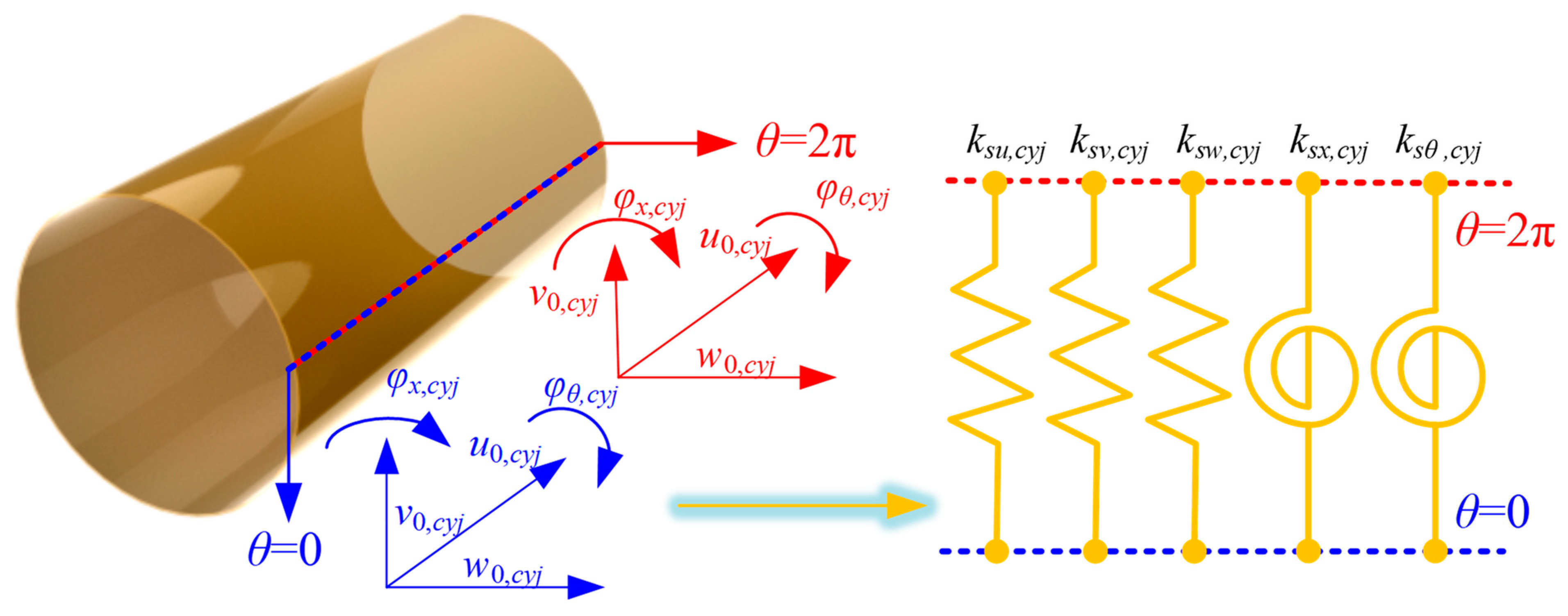
2.3. Continuity and General Boundary Conditions
For FGM closed cylindrical shell structures, the kinematic and physical continuity conditions need to be satisfied at the coupling boundary at
θ = 0 and
θ = 2π. At the continuous boundary, the continuity condition for the displacement can be expressed as
In this paper, by integrating the artificial virtual coupling technology, the corresponding continuity conditions can be satisfied by the corresponding coupling springs, which can meet the corresponding requirements, as shown in
Figure 2.
Furthermore, the coupling equations at the continuity condition of the FGM cylindrical shell can be expressed, respectively, as follows:
where
ksu/v/w/x/θ,cyj are the spring stiffness in various directions at the coupling edge. In addition, for cylindrical shell
j (
j = 1 and 2), the coupling potential energy
Us,
cyj between
θ = 0 and
θ = 2π needs to be considered based on the virtual spring technology. So, the elastic potential energy of the coupling potential energy is shown as
Furthermore, for annular plate
i (
i = 1 −
Na), the coupling potential energy
Us,
ani between
θ = 0 and
θ = 2π needs to be considered based on the virtual spring technology. So, the elastic potential energy of the coupling potential energy
Us,
ani is shown as
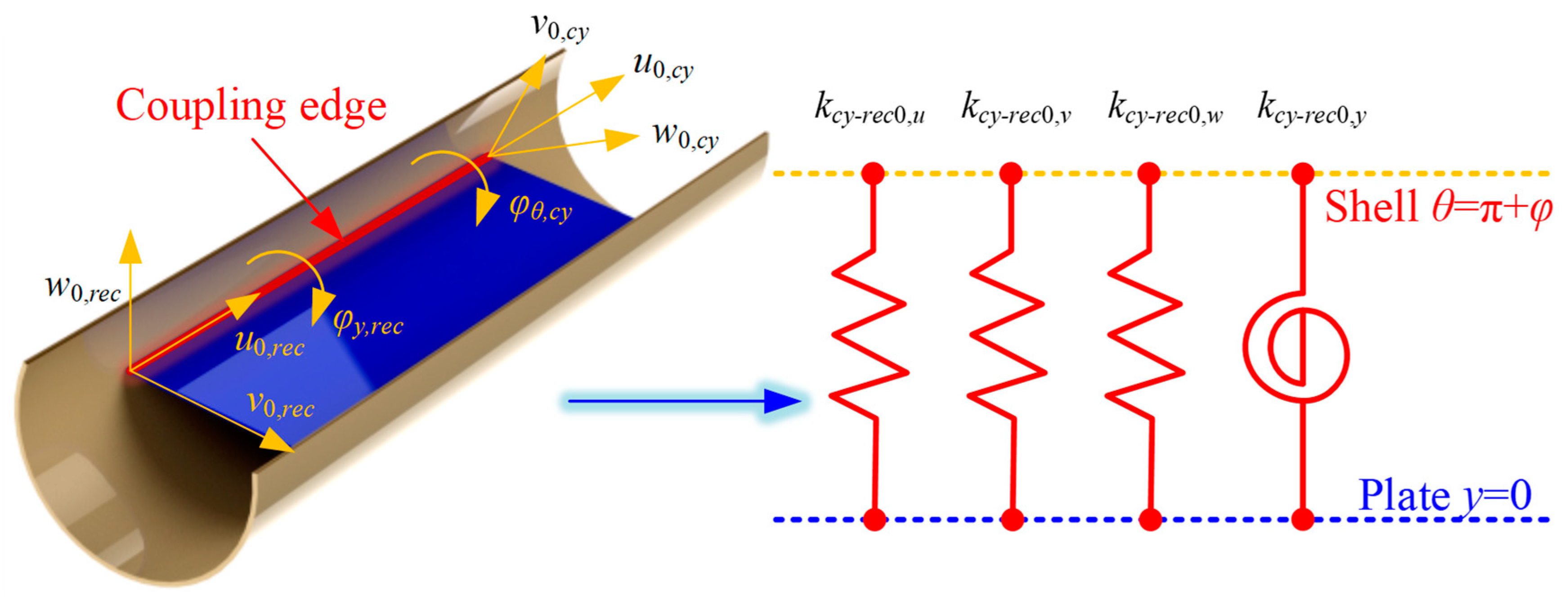
Also, the connection relationships of the cylindrical shell and rectangular plate at edges
y = 0 and
y =
b1 need to be considered, as
Similar to the FGM closed cylindrical shell, at the coupling boundary between the FGM cylindrical shell and the rectangular plate, the artificial virtual spring technique is employed to satisfy the corresponding continuity conditions by installing the corresponding coupling springs. In
Figure 3, the coupling effect model at the coupling edge
θ = π +
φ and
y = 0 are shown.
Based on this technology, the coupling equations at the connection edge
θ = π +
φ and
θ = π −
φ of the FGM cylindrical shell and the rectangular plate can be expressed as follows, respectively:
where
kcy-rec0/1, u/v/w/y are the linear and rotating elastic springs at the coupling edges. Also, the elastic coupling potential energy of cylindrical shell 1 and rectangular plate is conducted as
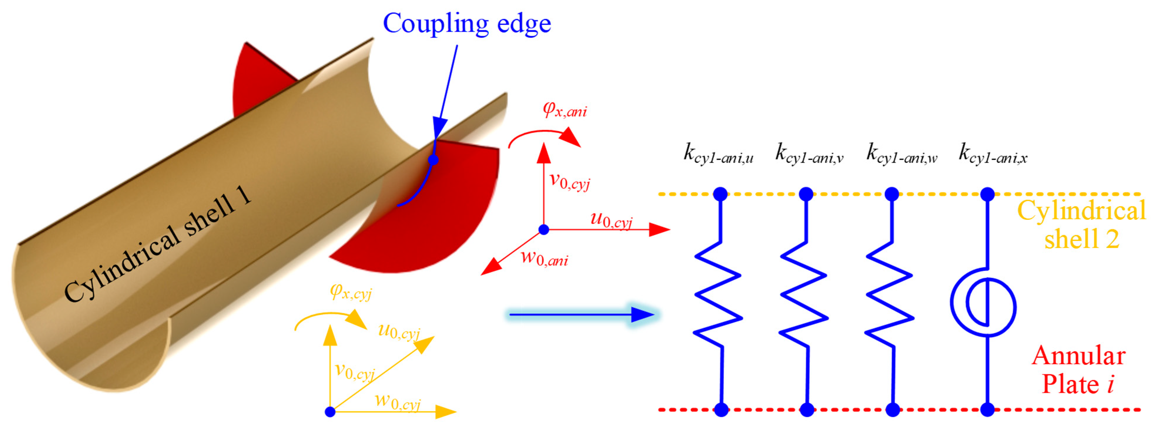
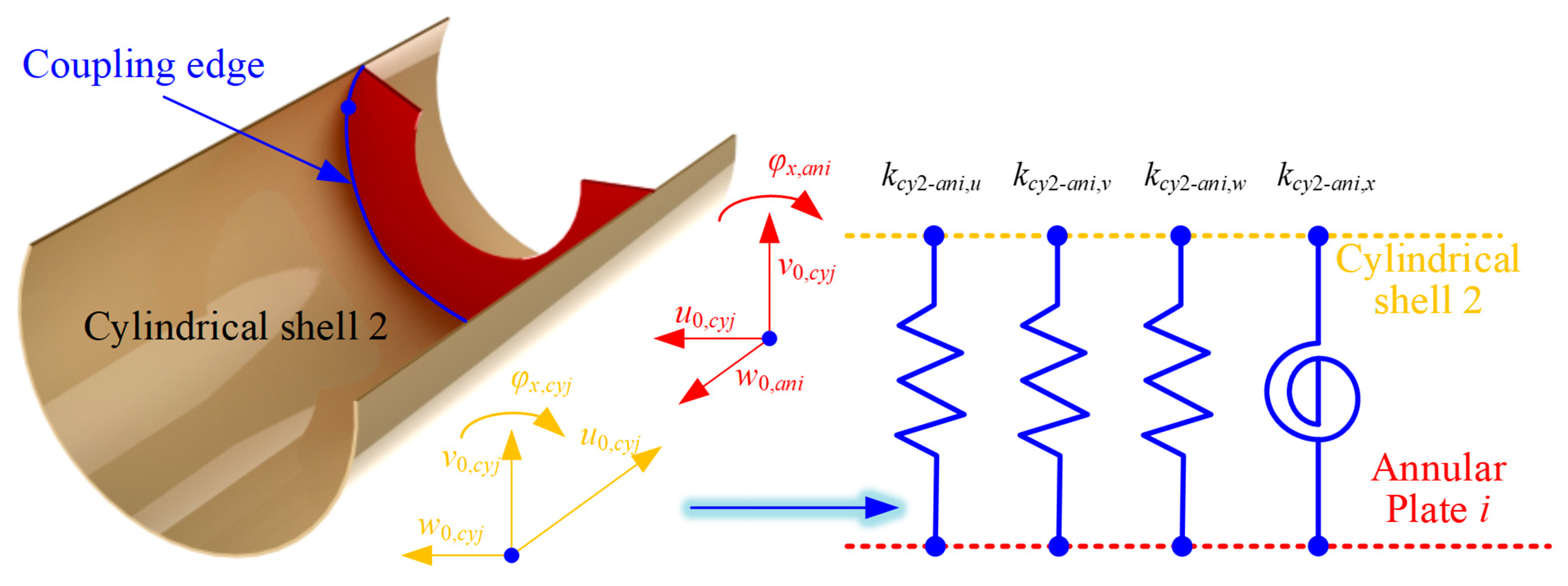
For the FGM cylindrical double-walled shell with internal structure in this article, the connection relationship between the cylindrical shell and annular plate should be considered. For the FGM coupled structure investigated in this paper, the coupling connection relationship between the FGM cylindrical shell and the circular plate needs to be considered in two cases. That is, the continuity conditions of the circular plate and cylindrical shell 1 (inner connection) and the circular plate and cylindrical shell 2 (outer connection) are considered, respectively.
The artificial virtual spring technique is used to express the continuity conditions for the two kinds of distinct conditions as follows:
where
kcy1/2-ani, u/v/w/x are the linear and rotating elastic springs at the coupling edges. Also, in
Figure 4 and
Figure 5, the representation of the coupling effect model at the coupling edge of the FGM annular plate and cylindrical shell is shown.
Furthermore, the potential energy of the FGM cylindrical double-walled shell with internal structure and the strain energy of the FGM shell/plate substructure with virtual coupling spring technology should be proposed. The elastic coupling potential energy of cylindrical shell 1/2 and annular plate
i is defined as
Next, similarly to the virtual coupling spring technology, the technology of the virtual boundary spring is selected for simulating boundary conditions of the FGM cylindrical double-walled shell with internal structure in this paper. The linear elastic springs and rotation springs are fixed at two ends of the cylindrical shell structure and the edge
x = 0 and
x =
a1 of the base plate.
where
Kux,0/a,
Kvx,0/a, and
Kwx,0/a are the linear elastic springs, and
Kxx,0/a and
Kyx,0/a are the rotation elastic springs for the base plate. Then, the potential energy of the FGM cylindrical shell by the virtual boundary spring technology is shown as
where
Ku0/L,j,
Kv0/L,j, and
Kw0/L,j are the linear elastic springs,
Kx0/L,j, and
Kθ0/L,j are the rotation elastic springs for the FGM cylindrical shell. In this article, the floating raft structure is coupled with cylindrical shell 1 in the FGM cylindrical double-walled shell with internal structure to simulate the cabin structure with a floating raft structure. In the floating raft structure, the spring damping simulator, which includes the elastic supporting springs and damper, is arranged at four connection points. So, the potential energy of the spring damping simulator is shown as
where
In Equation (40),
Kc,uj/vj/wj/xj/yj are the linear and rotation springs of the spring damping simulator and
c is the damping value. Then, the total elastic potential energy of the FGM cylindrical double-walled shell with internal structure by the virtual coupling spring technology, virtual boundary spring technology, and spring damping simulator is shown as
2.4. Energy Expressions
The Lagrangian function of the FGM cylindrical double-walled shell with an internal structure system is constructed from the energy term for the strain, the kinetic energy term for the FGM shell/plate substructure, and the total elastic potential energy term of the FGM coupled structure, and its expression is
where
ΠF is the energy functional by the external force at the point of excitation, as
in which
fx,
fy, and
fz is the external force which is applied in the
x,
y, and
z directions. According to the Rayleigh–Ritz method, the dynamic model for vibration analysis of the FGM cylindrical double-walled shell with internal structure can be obtained, expressed as
where
M,
C, and
K are, respectively, the mass, damping, and stiffness matrix for the FGM coupled structure system.
F is the external load vector.
Θ is the unknown coefficient vector with all expansions of unknown level expansion variables. For the free vibration solving of the FGM cylindrical double-walled shell with internal structure, the natural frequencies of the FGM cylindrical double-walled shell with internal structure under various boundary conditions can be easily solved by removing the external load vectors in Eq. Meanwhile, the forced vibration of the FGM cylindrical double-walled shell with internal structure can be obtained by solving the dynamics equation directly. With the modeling assumptions and computational approach established, we now present the results of the vibration analysis, including the natural frequencies and mode shapes for various configurations.


