
Study on Relationship Between Mechanical Properties and Water Absorption Characteristics of Mortars by Using Digital Image Correlation Method (DICM)

 ,
, 
Highlights
- The effect of water ingress on volume changing behaviors is observed by strain gauges and DICM in mortars of three different strengths.
- DICM is identified as useful technique to evaluate the characteristics like water absorption depth/rate and material deformability during water absorption in concrete materials.
- The water absorption rates, and maximum expansion strain decrease almost linearly with the increase in mechanical properties of the mortars.
Abstract
1. Introduction
2. Experimental Outlines
2.1. Materials and Mix Proportions
2.2. Test Specimens
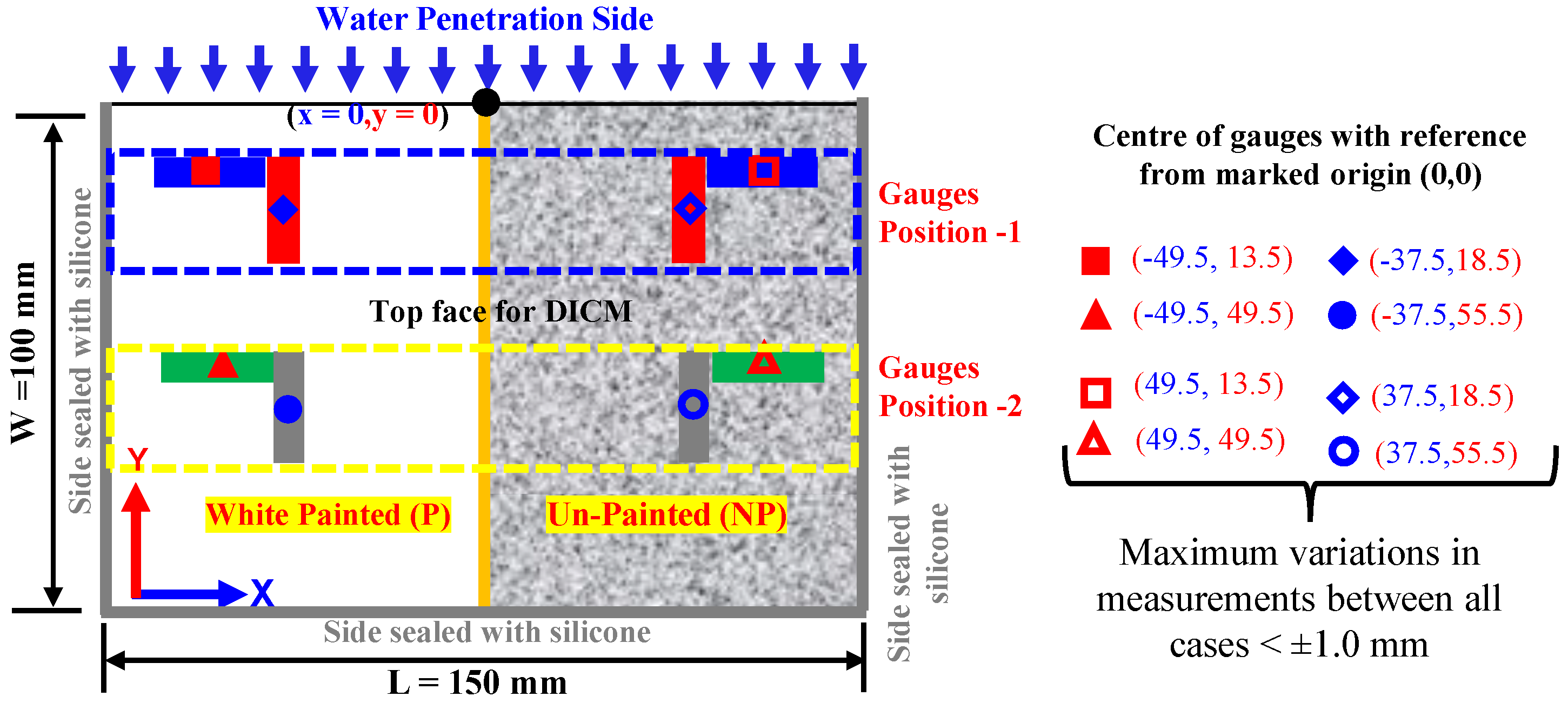
- All surfaces of the specimen were sealed by applying silicone except on one longer side/edge (to allow water absorption) and the top face (to be used for the DICM); masking tape was applied to avoid traces of silicone, while its application on other sides was used to seal them against water absorption.
- The masking tape was only cut at designated positions on the planner face at the marked points to attach the strain gauges. It also served as a guide for the positioning of gauges in a particular direction at intended points, as illustrated in Figure 1. The face for the DICM was divided into two halves, i.e., the painted side (P) and the unpainted side (NP). On this face, eight (08) general-purpose surface strain gauges with a gauge length of 10 mm were attached. Moreover, the arrangement of gauges was kept identical on both halves in the x- and y-axes with respect to the direction of water absorption.
- c.
- After the attachment of surface strain gauges, the specimen was placed in a glass chamber and kept there for approximately 24 h. Afterwards, the half face was coated with matte-type white spray paint to decrease the influence of color change and to achieve good-quality speckles for the DICM, and the other half face was left unpainted to differentiate between DICM measurements during the water absorption process. It is worth mentioning that matte-type white spray paint was used for coating because its layer did not make any thin film over the surface, and also, it does not affect the deformation measurements in the DICM (for details, readers may consult [63,64]).
- d.
2.3. Test Methods
2.3.1. Water Absorption Test (WA)
2.3.2. Description of Digital Image Correlation Method (DICM)
2.3.3. Uniaxial Compression Test (CT)
3. Determination of Strain Development During Water Absorption Using Surface Strain Gauges
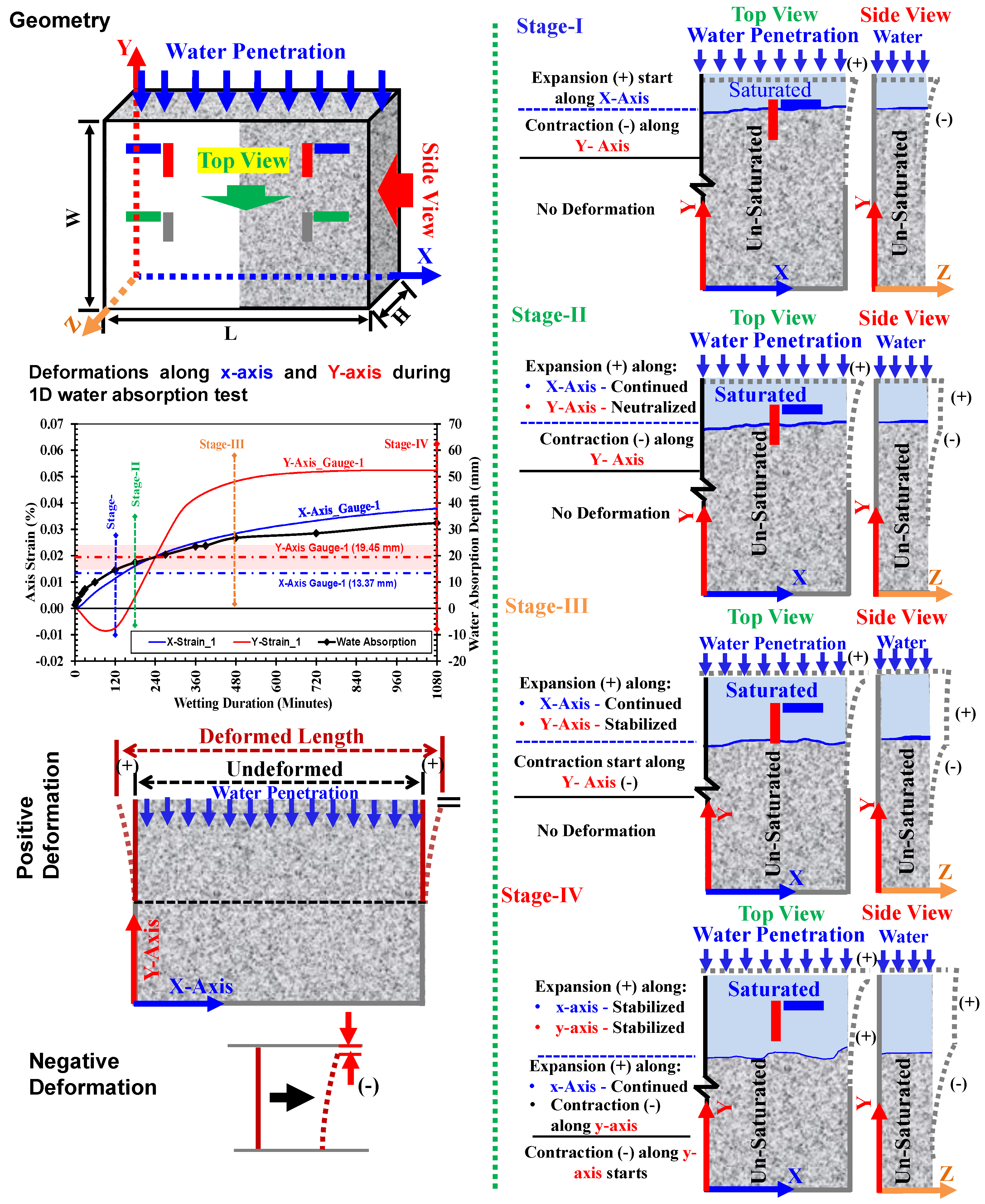
3.1. Strain Development Along x-Axis and y-Axis Directions
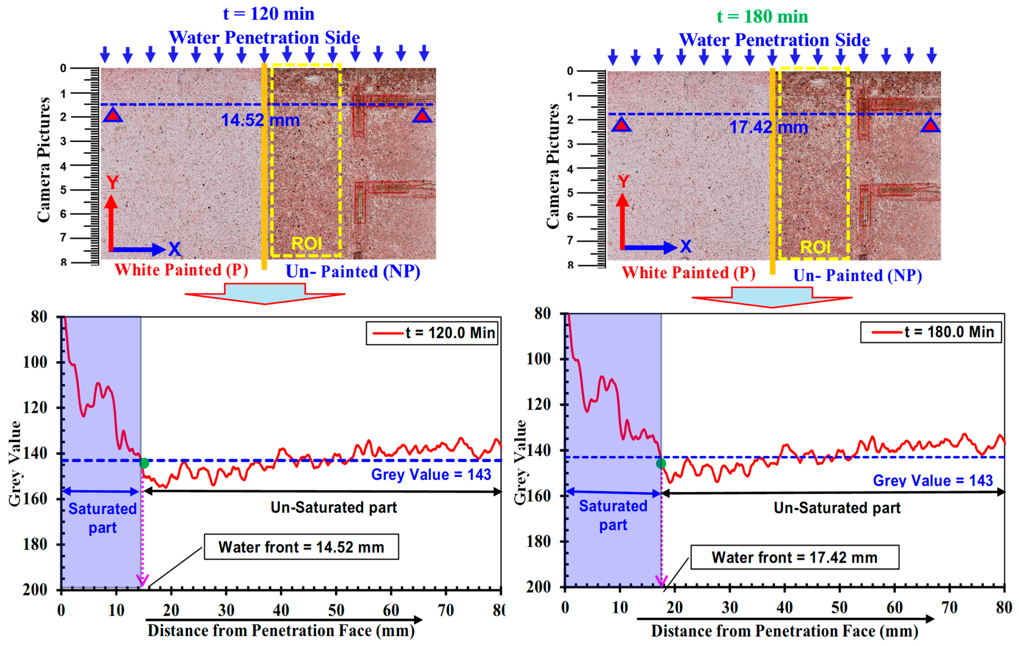
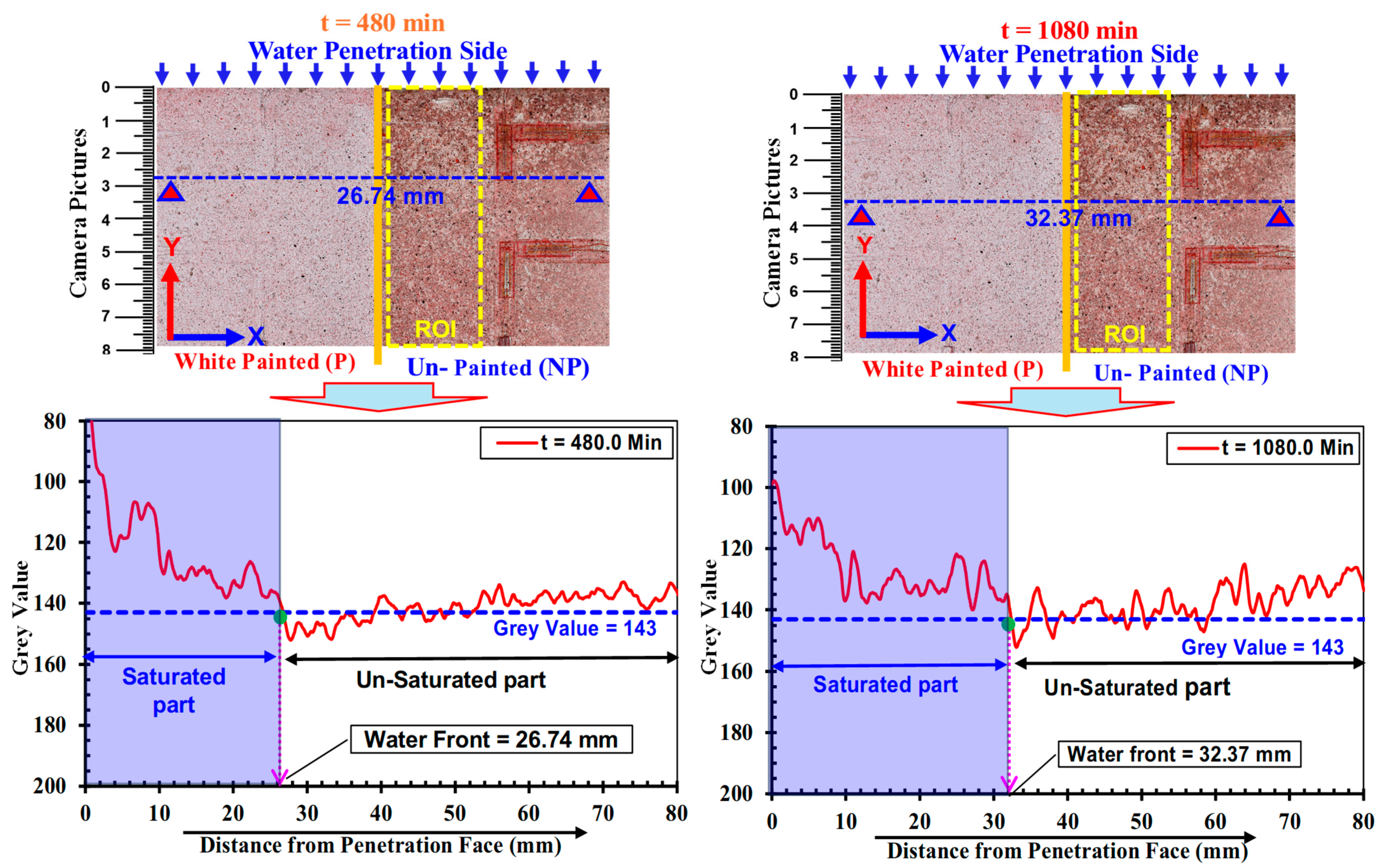
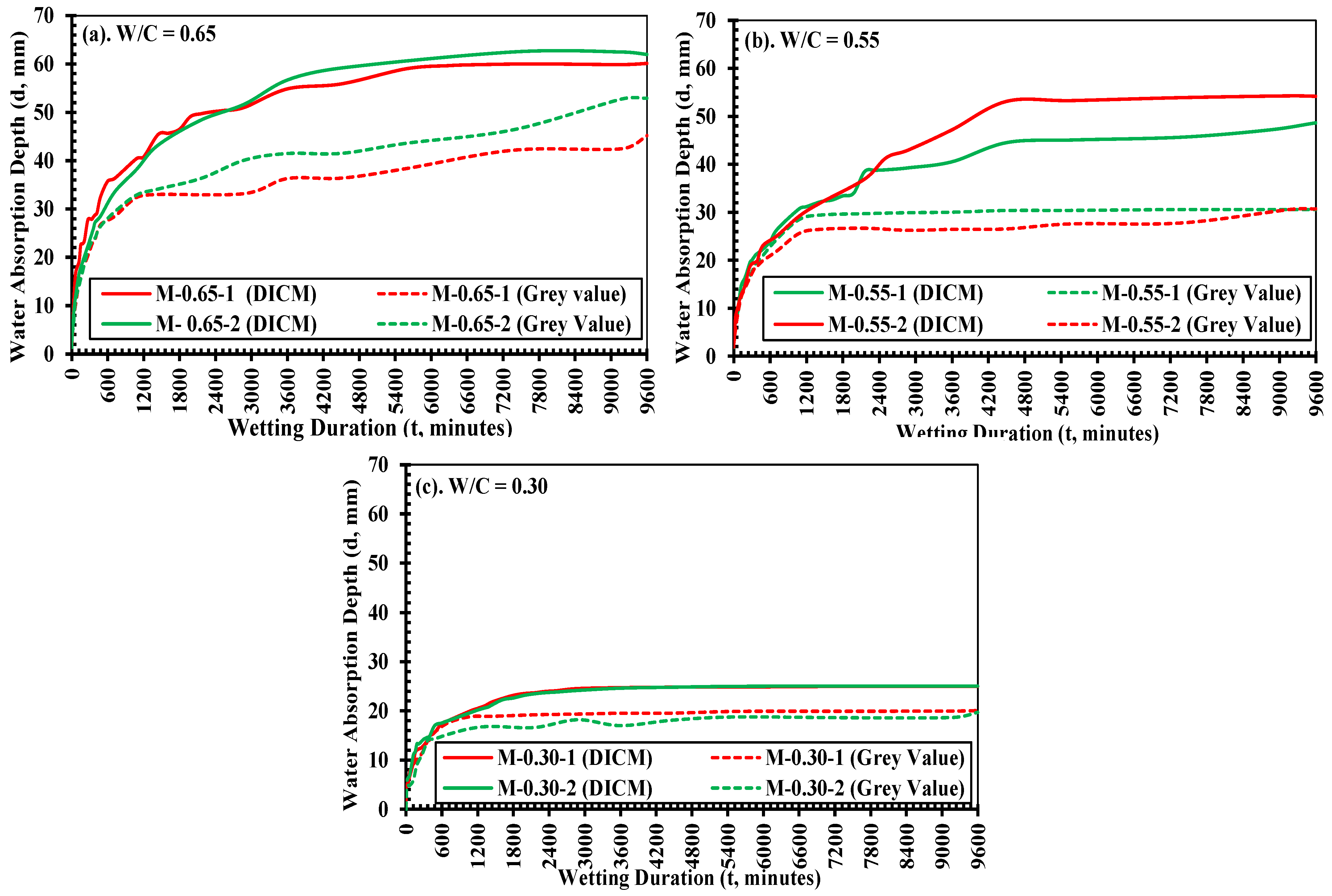
3.2. Water Absorption Depth Determined by Grayscale
3.3. Three-Dimensional Deformation Behavior During Water Absorption
- At stage-I: The waterfront reached the y-axis gauge (red mark) at position-1, as shown by the blue line in the top view, indicating the possible expansion along the x, y, and z-axis of the specimen in its saturated part. Since the portion below the gauge was still unsaturated, this part exhibited contraction due to small bending occurring in the z-axis direction. However, the positive strain in the x-axis was observed owing to the uniform expansion.
- At stage-II: The half of the y-axis strain gauge was covered in the saturated part (indicating positive strain) and half unsaturated (negative strain occurs due to contraction as a result of bending deformation). It is true, therefore, that both the strains balanced each other, and the y-axis strain became neutralized. But at the same time, the x-axis strain continued to show a gradual increase due to continued expansion.
- At stage-III: The moment when the full underneath part of the y-axis gauge was saturated and there was the maximum possible deformations along the y-axis was reached. There was a rapid increase in the y-axis strain just before reaching this stage, e.g., when water progressed through its gauge. But soon after the full part below the y-axis strain gauge became saturated, and the stabilized condition in expansion was achieved.
- At stage-IV: The water absorption increased, resulting in more progressed volumetric changes in the specimen.
4. Implementation of DICM to Evaluate Strain Development During Water Absorption
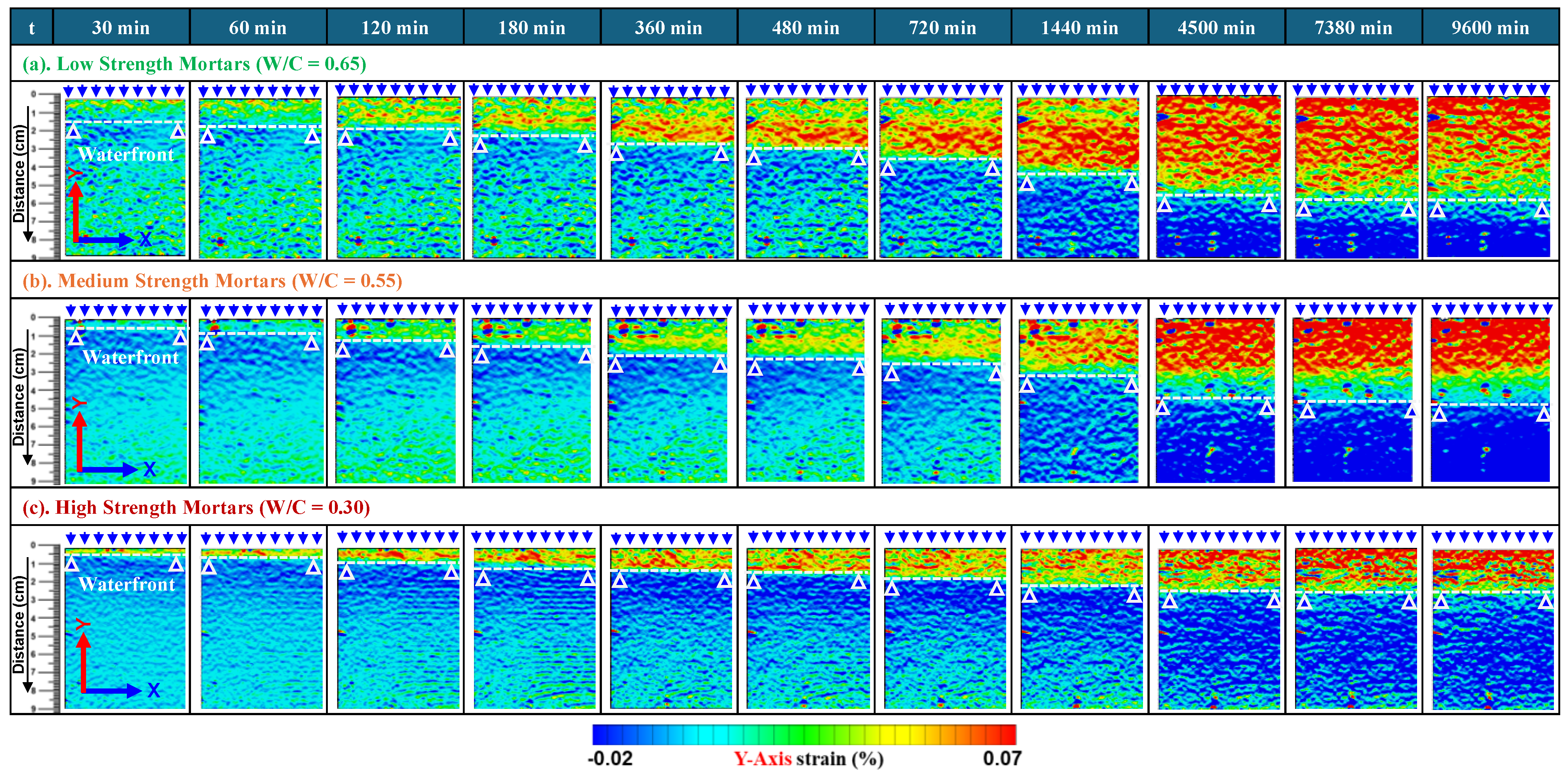
4.1. Spatial Distribution of Strain During Water Absorption in Low-Strength Mortars
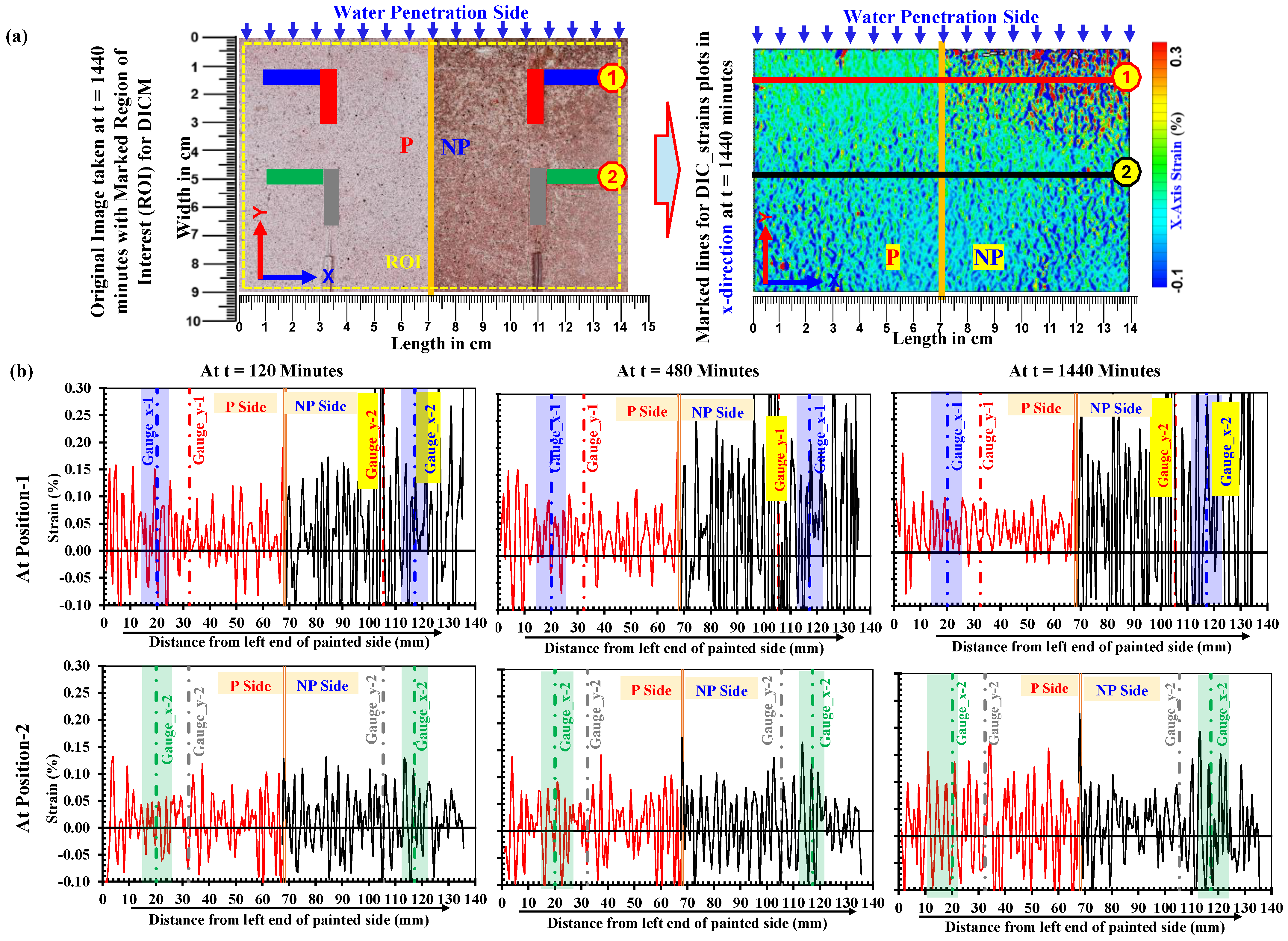
4.1.1. Variation in Strain Along x-Axis
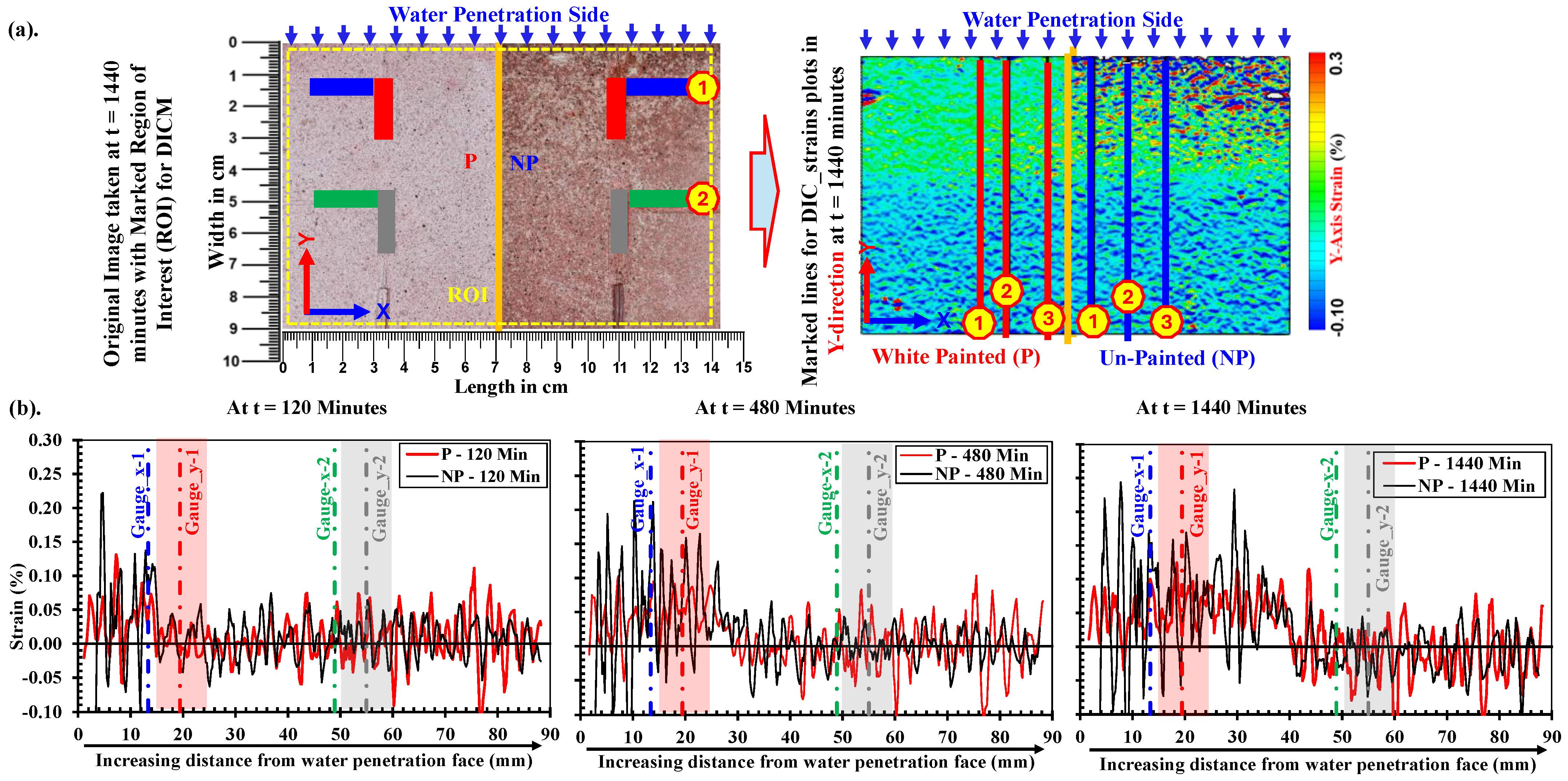
4.1.2. Variation in Strain Along y-Axis
4.2. Strain Recorded by Surface Strain Gauges vs. Strains by DICM (Pε_DICM vs. Pε_Gauges)
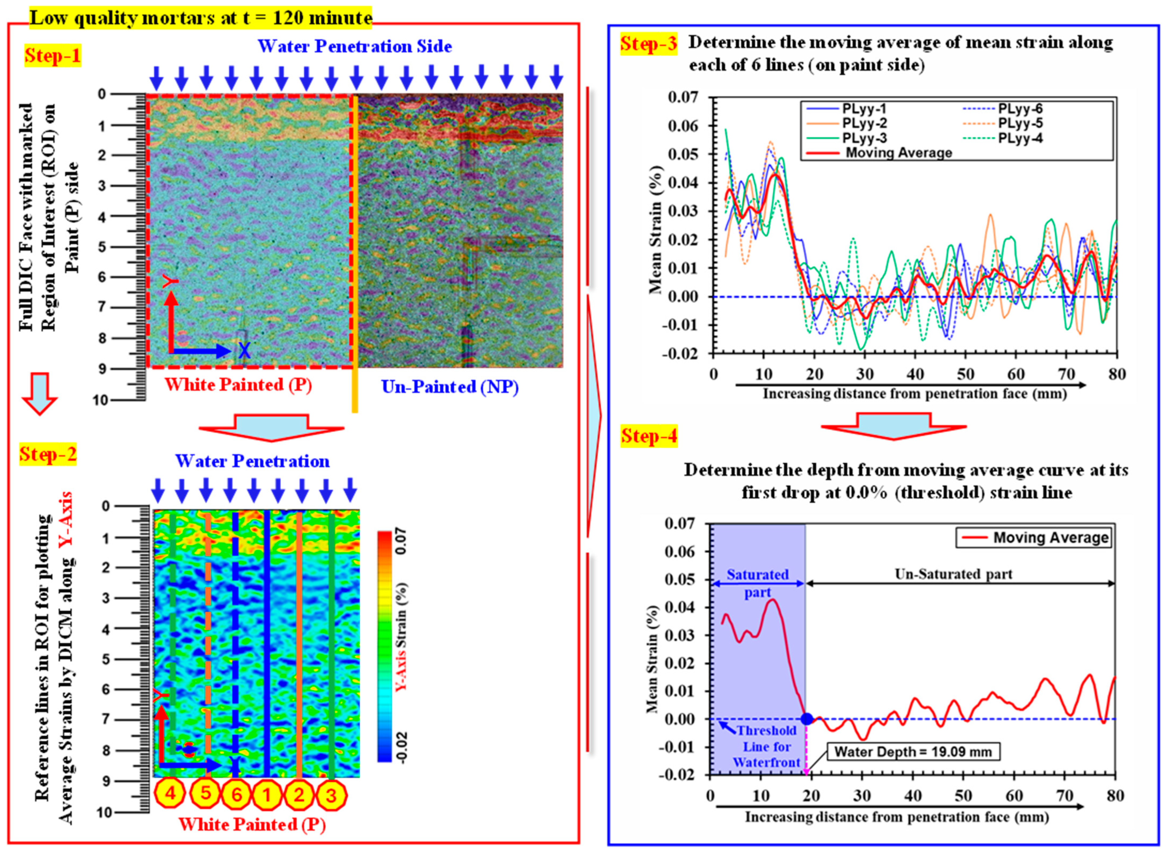
4.3. Evaluating Water Absorption Characteristics Obtained by DICM
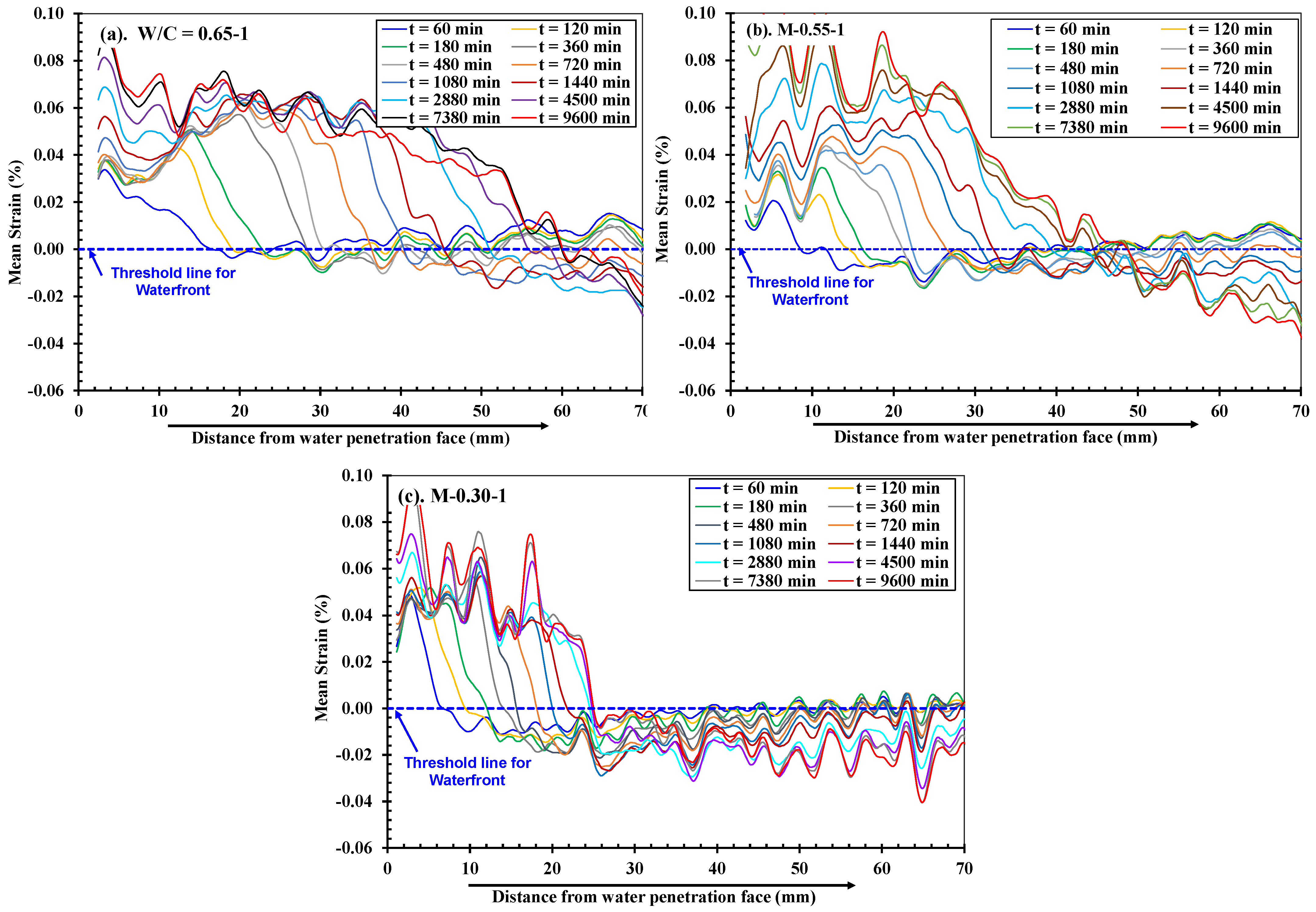
4.3.1. Full Field Deformations in Mortars Along y-Axis Direction
4.3.2. Comparison of Progression of Full Field Deformations in y-Axis Direction
5. Relationship Between Water Absorption Characteristics and the Mechanical Properties of Mortars of Different Strengths
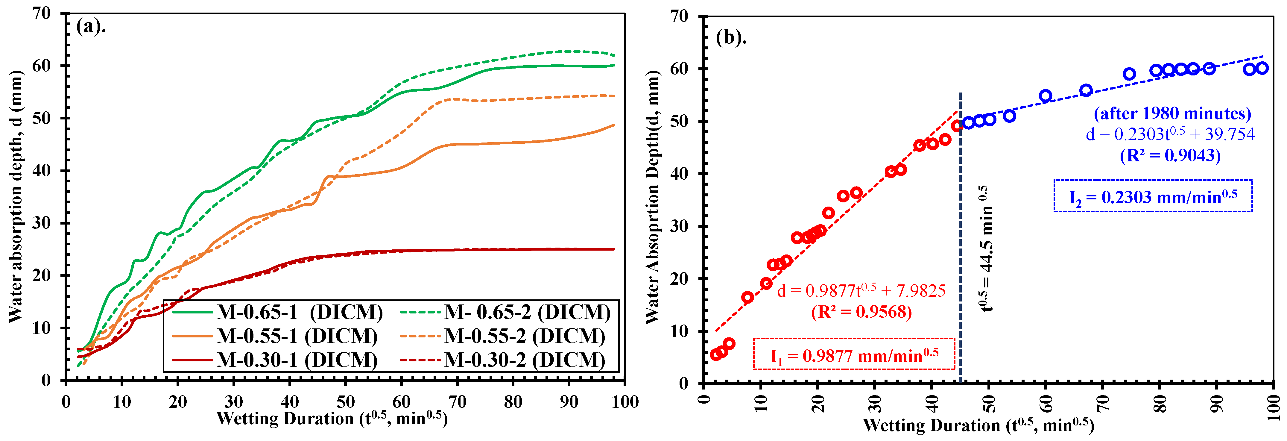
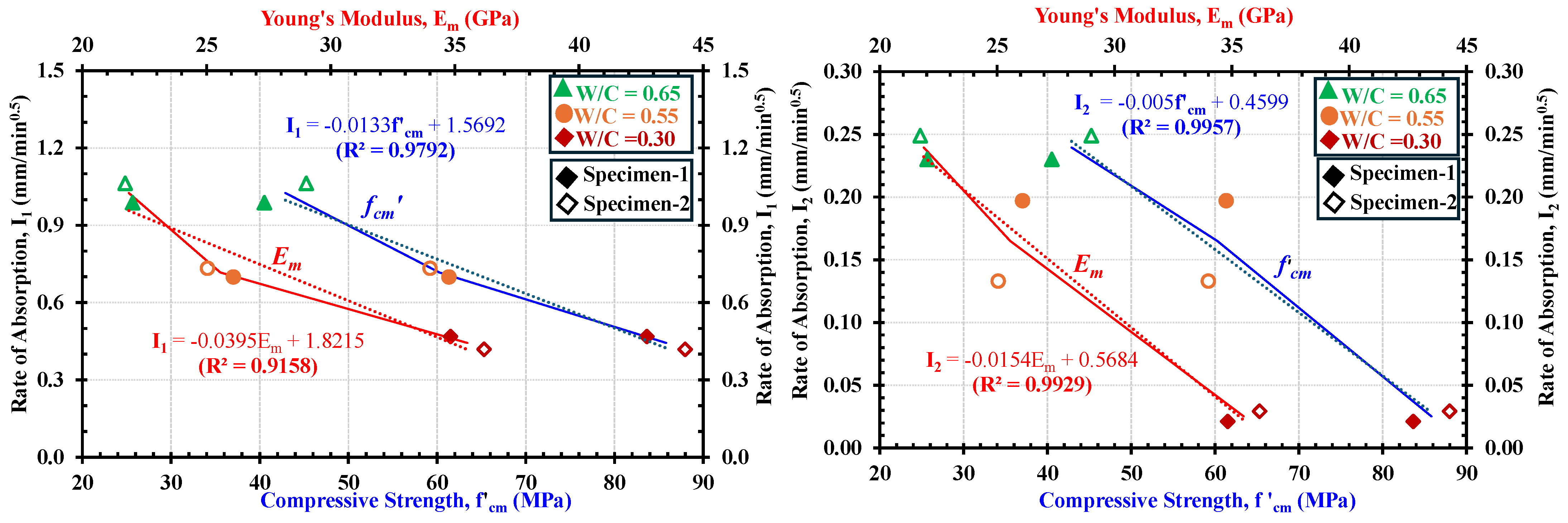
5.1. Relationship Between Rate of Water Absorption (I) and the Mechanical Properties
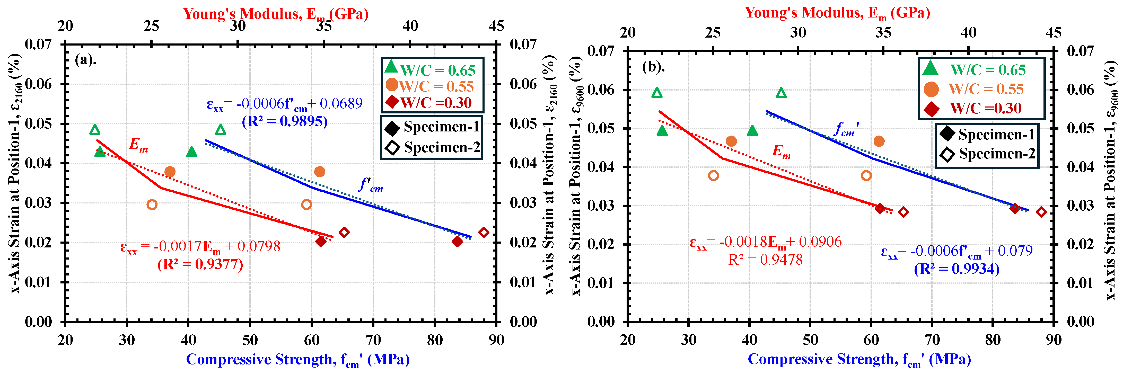
5.2. Relationship Between Maximum Developed Strain Along x-Axis (i.e., εxx) in Fully Saturated Regions and the Mechanical Properties
6. Conclusions
- Water ingress has an instant effect on the volume changes (expansion) in the cement-based materials owing to the hygroscopic nature of the cement hydrates (i.e., the C-S-H). Moreover, the continuous monitoring/evaluation of strains at specimens’ surfaces during the water absorption process indirectly provides physical evidence of such an internal swelling phenomenon in concrete materials during the process of water absorption.
- The DICM is an effective method to evaluate the volumetric changes in concrete materials by evaluating the strains at the specimen surfaces during the water absorption process. However, the calculations in the DICM are strongly influenced by the changes in the contrast of the image within the saturated regions of the test specimen surfaces and result in pseudo strains. Therefore, applying the DICM with water absorption in concrete materials requires their surface to be coated with matte-type spray paints first and then enhanced by speckling to achieve good test results.
- The deformability and the water absorption depth/rate in concrete materials are directly related to each other and depend on their mix compositions. The progression in surface strains measured in the DICM provided more reliable evaluations of water ingress rates into the mortars, thereby indicating the closest boundary between primary and secondary liquid water absorption processes. The water absorption depths and the tendencies in expansion strains in saturated parts were different for specimens of three different strengths. However, in all three strengths, the depth (d) vs. square root time (t0.5) curves deviated from a linear relationship after the same time, i.e., 1980 min, resulting in highlighting that the largest strains occur within the primary absorption period, after which, strains progress slowly owing to the slow water absorption in the secondary absorption period.
- Concrete materials with lower w/c ratios (high strength) experience lower water absorption rates. On the other hand, mortars with lower strengths will allow more rapid water absorption and other liquids or ions owing to the presence of more pore fractions. Moreover, the primary and secondary absorption rates showed almost linear relationships with mechanical properties such as compressive strength and the Young’s modulus of mortars.
- The volume changes in mortars due to water absorption in the saturated part have a clear relationship with the mechanical properties. The results indicated that the evaluated durability properties related to water permeation not only relate to the water absorption rate but also to the compressive strength, Young’s modulus, and the volume change due to saturation.
Author Contributions
Funding
Institutional Review Board Statement
Informed Consent Statement
Data Availability Statement
Acknowledgments
Conflicts of Interest
References
- Mehta, P.K.; Monteiro, P.J.M. Concrete: Microstructure, Properties, and Materials, 4th ed.; McGraw-Hill Education: New York, NY, USA, 2014. [Google Scholar]
- Castro, J.; Bentz, D.; Weiss, J. Effect of sample conditioning on the water absorption of concrete. Cem. Concr. Compos. 2011, 33, 805–813. [Google Scholar] [CrossRef]
- Sabir, B.B.; Wild, S.; O’Farrell, M. A water sorptivity test for mortar and concrete. Mater. Struct. 1998, 31, 568–574. [Google Scholar] [CrossRef]
- Maltais, Y.; Samson, E.; Marchand, J. Predicting the durability of Portland cement systems in aggressive environments—Laboratory validation. Cem. Concr. Res. 2004, 34, 1579–1589. [Google Scholar] [CrossRef]
- Khanzadeh Moradllo, M.; Sudbrink, B.; Ley, M.T. Determining the effective service life of silane treatments in concrete bridge decks. Constr. Build. Mater. 2016, 116, 121–127. [Google Scholar] [CrossRef]
- Mendes, A.; Sanjayan, J.G.; Gates, W.P.; Collins, F. The influence of water absorption and porosity on the deterioration of cement paste and concrete exposed to elevated temperatures, as in a fire event. Cem. Concr. Compos. 2012, 34, 1067–1074. [Google Scholar] [CrossRef]
- Hearn, N.; Hooton, R.; Mills, R. Pore structure and permeability. In Significance of Tests and Properties of Concrete and Concrete-Making Materials; ASTM International: West Conshohocken, PA, USA, 2006; pp. 240–253. [Google Scholar]
- Espinosa, R.M.; Franke, L. Influence of the age and drying process on pore structure and sorption isotherms of hardened cement paste. Cem. Concr. Res. 2006, 36, 1969–1984. [Google Scholar] [CrossRef]
- Krus, M.; Hansen, K.K.; Kinzel, H.M. Porosity and liquid absorption of cement paste. Mater. Struct. 1997, 30, 43–49. [Google Scholar] [CrossRef]
- Ramli, M.; Tabassi, A.A.; Hoe, K.W. Porosity, pore structure and water absorption of polymer-modified mortars: An experimental study under different curing conditions. Compos. B Eng. 2013, 55, 221–233. [Google Scholar] [CrossRef]
- Hanžič, L.; Ilić, R. Relationship between liquid sorptivity and capillarity in concrete. Cem. Concr. Res. 2003, 33, 1385–1388. [Google Scholar] [CrossRef]
- Norman, R. Physics and thermodynamics of capillary. Ind. Eng. Chem. 1970, 62, 32–56. [Google Scholar]
- Hong, S.; Yao, W.; Guo, B.; Lin, C.; Dong, B.; Li, W.; Hou, D.; Xing, F. Water distribution characteristics in cement paste with capillary absorption. Constr. Build. Mater. 2020, 240, 117839. [Google Scholar] [CrossRef]
- Hall, C. Water sorptivity of mortars and concretes: A review. Mag. Concr. Res. 1989, 41, 51–61. [Google Scholar] [CrossRef]
- Martys, N.S.; Ferraris, C.F. Capillary transport in mortars and concrete. Cem. Concr. Res. 1997, 27, 747–760. [Google Scholar] [CrossRef]
- Hall, C. Anomalous diffusion in unsaturated flow: Fact or fiction? Cem. Concr. Res. 2007, 37, 378–385. [Google Scholar] [CrossRef]
- Zhang, S.P.; Zong, L. Evaluation of relationship between water absorption and durability of concrete materials. Adv. Mater. Sci. Eng. 2014, 2014, 1–8. [Google Scholar] [CrossRef]
- Zheng, F.; Hong, S.; Hou, D.; Dong, B.; Kong, Z.; Jiang, R. Rapid visualization and quantification of water penetration into cement paste through cracks with X-ray imaging. Cem. Concr. Compos. 2022, 125, 104318. [Google Scholar] [CrossRef]
- Dias, W.P.S. Reduction of concrete sorptivity with age through carbonation. Cem. Concr. Res. 1992, 22, 839–848. [Google Scholar] [CrossRef]
- Khanzadeh Moradllo, M.; Ley, M.T. Quantitative measurement of the influence of degree of saturation on ion penetration in cement paste by using X-ray imaging. Constr. Build. Mater. 2017, 141, 113–129. [Google Scholar] [CrossRef]
- Henkensiefken, R.; Castro, J.; Bentz, D.; Nantung, T.; Weiss, J. Water absorption in internally cured mortar made with water-filled lightweight aggregate. Cem. Concr. Res. 2009, 39, 883–892. [Google Scholar] [CrossRef]
- ASTM C1585; Standard Test Method for Measurement of Rate of Absorption of Water by Hydraulic-Cement Concretes. ASTM International: West Conshohocken, PA, USA, 2020.
- Zhutovsky, S.; Hooton, R.D. Role of sample conditioning in water absorption tests. Constr. Build. Mater. 2019, 215, 918–924. [Google Scholar] [CrossRef]
- Van Belleghem, B.; Montoya, R.; Dewanckele, J.; Steen, N.V.D.; De Graeve, I.; Deconinck, J.; Cnudde, V.; Van Tittelboom, K.; De Belie, N. Capillary water absorption in cracked and uncracked mortar A comparison between experimental study and finite element analysis. Constr. Build. Mater. 2016, 110, 154–162. [Google Scholar] [CrossRef]
- Alderete, N.M.; Villagrán Zaccardi, Y.A.; De Belie, N. Physical evidence of swelling as the cause of anomalous capillary water uptake by cementitious materials. Cem. Concr. Res. 2019, 120, 256–266. [Google Scholar] [CrossRef]
- Tang, L.; Basheer, P.A.M. Resistance of Concrete to Chloride Ingress: Testing and Modelling; CRC Press: London, UK, 2012. [Google Scholar]
- Fries, N.; Dreyer, M. An analytic solution of capillary rise restrained by gravity. J. Colloid. Interface Sci. 2008, 320, 259–263. [Google Scholar] [CrossRef]
- Muller, A.C.A.; Scrivener, K.L.; Gajewicz, A.M.; McDonald, P.J. Use of bench-top NMR to measure the density, composition and desorption isotherm of C-S-H in cement paste. Microporous Mesoporous Mater. 2013, 178, 99–103. [Google Scholar] [CrossRef]
- Huang, L.; Tang, L.; Dong, Z.; Abdulahi, B.A.; Yang, Z. Effect of curing regimes on composition and microstructure of blended pastes: Insight into later-age hydration mechanism. Cem. Concr. Res. 2025, 189, 107785. [Google Scholar] [CrossRef]
- Wyrzykowski, M.; McDonald, P.J.; Scrivener, K.L.; Lura, P. Water redistribution within the microstructure of cementitious materials due to temperature changes studied with 1H NMR. J. Phys. Chem. C 2017, 121, 27950–27962. [Google Scholar] [CrossRef]
- Rymarczyk, T. New methods to determine moisture areas by electrical impedance tomography. Int. J. Appl. Electromagn. Mech. 2016, 52, 79–87. [Google Scholar] [CrossRef]
- Smyl, D.; Rashetnia, R.; Seppänen, A.; Pour-Ghaz, M. Can electrical resistance tomography be used for imaging unsaturated moisture flow in cement-based materials with discrete cracks? Cem. Concr. Res. 2017, 91, 61–72. [Google Scholar] [CrossRef]
- Dong, B.; Gu, Z.; Qiu, Q.; Liu, Y.; Ding, W.; Xing, F.; Hong, S. Electrochemical feature for chloride ion transportation in fly ash blended cementitious materials. Constr. Build. Mater. 2018, 161, 577–586. [Google Scholar] [CrossRef]
- Bigger, R.; Blaysat, B.; Boo, C.; Grewer, M.; Hu, J.; Jones, A.; Klein, M.; Lava, P.; Pankow, M.; Raghavan, K.; et al. A Good Practices Guide for Digital Image Correlation. Jones, E., Iadicola, M., Eds.; 2018. Available online: https://www.idics.org/guide/DICGoodPracticesGuide_PrintVersion-V5h-181024.pdf (accessed on 24 January 2025).
- Oats, R.C.; Dai, Q.; Head, M. Digital Image Correlation Advances in Structural Evaluation Applications: A Review. Pr. Period. Struct. Des. Constr. 2022, 27, 04022035. [Google Scholar] [CrossRef]
- Bogusz, P.; Krasoń, W.; Pazur, K. Application of Digital Image Correlation for Strain Mapping of Structural Elements and Materials. Materials 2024, 17, 2567. [Google Scholar] [CrossRef] [PubMed]
- Mousa, M.A.; Yussof, M.M.; Hussein, T.S.; Assi, L.N.; Ghahari, S. A Digital Image Correlation Technique for Laboratory Structural Tests and Applications: A Systematic Literature Review. Sensors 2023, 23, 2678. [Google Scholar] [CrossRef]
- Peters, W.H.; Ranson, W.F. Digital imaging techniques in experimental stress analysis. Opt. Eng. 1982, 21, 427–431. [Google Scholar] [CrossRef]
- Pan, B.; Qian, K.; Xie, H.; Asundi, A. Two-dimensional digital image correlation for in-plane displacement and strain measurement: A review. Meas. Sci. Technol. 2009, 20, 062001. [Google Scholar] [CrossRef]
- Zhong, F.Q.; Indurkar, P.P.; Quan, C.G. Three-dimensional digital image correlation with improved efficiency and accuracy. Measurement 2018, 128, 23–33. [Google Scholar] [CrossRef]
- Huang, Y.; He, X.; Wang, Q.; Xiao, J. Deformation field and crack analyses of concrete using digital image correlation method. Front. Struct. Civ. Eng. 2019, 13, 1183–1199. [Google Scholar] [CrossRef]
- Zhou, T.; Chen, J.; Xie, H.; Zhou, C.; Wang, F.; Zhu, J. Failure and mechanical behaviors of sandstone containing a pre-existing flaw under compressive–shear loads: Insight from a digital image correlation (DIC) analysis. Rock. Mech. Rock. Eng. 2022, 55, 4237–4256. [Google Scholar] [CrossRef]
- del Rey Castillo, E.; Allen, T.; Henry, R.; Griffith, M.; Ingham, J. Digital image correlation (DIC) for measurement of strains and displacements in coarse, low volume-fraction FRP composites used in civil infrastructure. Compos. Struct. 2019, 212, 43–57. [Google Scholar] [CrossRef]
- Khoo, S.W.; Karuppanan, S.; Tan, C.S. A review of surface deformation and strain measurement using two-dimensional digital image correlation. Metrol. Meas. Syst. 2016, 23, 461–480. [Google Scholar] [CrossRef]
- Romanowicz, P.J.; Szybiński, B.; Wygoda, M. Assessment of Digital Image Correlation Effectiveness and Quality in Determination of Surface Strains of Hybrid Steel/Composite Structures. Materials 2024, 17, 3367. [Google Scholar] [CrossRef]
- Jiang, Y.; Jin, Z.; Zhao, T.; Chen, Y.; Chen, F. Strain field of reinforced concrete under accelerated corrosion by digital image correlation technique. J. Adv. Concr. Technol. 2017, 15, 290–299. [Google Scholar] [CrossRef]
- Zhang, S.; Liu, R.; Lu, C.; Gao, Y.; Xu, J.; Yao, L.; Chen, Y. Application of digital image correlation to study the influence of the water/cement ratio on the interfacial transition zone in cement-based materials. Constr. Build. Mater. 2023, 367, 130287. [Google Scholar] [CrossRef]
- Bertelsen, I.; Kragh, C.; Cardinaud, G.; Ottosen, L.; Fischer, G. Quantification of plastic shrinkage cracking in mortars using digital image correlation. Cem. Concr. Res. 2019, 123, 105774. [Google Scholar] [CrossRef]
- Adamczak-Bugno, A.; Lipiec, S.; Vavruš, M.; Koteš, P. Non-destructive methods and numerical analysis used for monitoring and analysis of fibre concrete deformations. Materials 2022, 15, 7145. [Google Scholar] [CrossRef] [PubMed]
- Srimook, P.; Maruyama, I. Anomalous moisture transport in dried cementitious material: A numerical analysis. Constr. Build. Mater. 2024, 449, 135678. [Google Scholar] [CrossRef]
- Dzaye, E.D.; Tsangouri, E.; Spiessens, K.; De Schutter, G.; Aggelis, D.G. Digital image correlation (DIC) on fresh cement mortar to quantify settlement and shrinkage. Arch. Civ. Mech. Eng. 2019, 19, 205–214. [Google Scholar] [CrossRef]
- Ogawa, K.; Hashimoto, C.; Igarashi, G.; Maruyama, I. Time-dependent strain distribution of mortar in concrete during water uptake monitored by digital image correlation method. Cem. Sci. Concr. Technol. 2023, 77, 222–230. [Google Scholar] [CrossRef]
- Usman, M.; Nakamura, H.; Miura, T. Application of digital image correlation (DIC) method to evaluate the water absorption in different qualities of concrete. In Proceedings of the Fib Symposium 2024, Christchurch, New Zealand, 11–13 November 2024; Henry, R., Palermo, A., Eds.; Fib Publishing House: Zurich, Switzerland, 2024; pp. 1105–1114. [Google Scholar]
- Reu, P. All about speckles: Contrast. Exp. Tech. 2015, 39, 1–2. [Google Scholar] [CrossRef]
- Pan, B.; Xie, H.; Wang, Z. Equivalence of digital image correlation criteria for pattern matching. Appl. Opt. 2010, 49, 5501–5509. [Google Scholar] [CrossRef]
- Pan, B.; Li, K. A fast digital image correlation method for deformation measurement. Opt. Lasers Eng. 2011, 49, 841–847. [Google Scholar] [CrossRef]
- Basheer, L.; Cleland, D.J. Durability and water absorption properties of surface treated concretes. Mater. Struct. 2011, 44, 957–967. [Google Scholar] [CrossRef]
- Al-Amoudi, O.S.B.; Al-Kutti, W.A.; Ahmad, S.; Maslehuddin, M. Correlation between compressive strength and certain durability indices of plain and blended cement concretes. Cem. Concr. Compos. 2009, 31, 672–676. [Google Scholar] [CrossRef]
- Zhuang, S.; Wang, Q.; Zhang, M. Water absorption behaviour of concrete: Novel experimental findings and model characterization. J. Build. Eng. 2022, 53, 104568. [Google Scholar] [CrossRef]
- Snoeck, D.; Velasco, L.F.; Mignon, A.; Van Vlierberghe, S.; Dubruel, P.; Lodewyckx, P.; De Belie, N. The influence of different drying techniques on the water sorption properties of cement-based materials. Cem. Concr. Res. 2014, 64, 54–62. [Google Scholar] [CrossRef]
- Wu, Z.; Wong, H.S.; Buenfeld, N.R. Influence of drying-induced microcracking and related size effects on mass transport properties of concrete. Cem. Concr. Res. 2015, 68, 35–48. [Google Scholar] [CrossRef]
- Beaudoin, J.J.; Tamtsia, B.T. Effect of drying methods on microstructural changes in hardened cement paste: An A.C. impedance spectroscopy evaluation. J. Adv. Concr. Technol. 2004, 2, 377–388. [Google Scholar] [CrossRef]
- Szalai, S.; er Fehér, V.; Kurhan, D.; Németh, A.; Sysyn, M.; Fischer, S. Optimization of surface cleaning and painting methods for DIC measurements on automotive and railway aluminum materials. Infrastructures 2023, 8, 25. [Google Scholar] [CrossRef]
- Pérez, J.A.; Coppieters, S.; Debruyne, D. Influence of the paint coating thickness in digital image correlation experiments. Int. J. Comput. Inf. Eng. 2015, 9, 1660–1664. [Google Scholar]
- Miura, T.; Sato, K.; Nakamura, H. The role of microcracking on the compressive strength and stiffness of cracked concrete with different crack widths and angles evaluated by DIC. Cem. Concr. Compos. 2020, 114, 103768. [Google Scholar] [CrossRef]
- Schreier, H.; Orteu, J.-J.; Sutton, M.A. Image Correlation for Shape, Motion and Deformation Measurements; Springer: Boston, MA, USA, 2009. [Google Scholar]
- Dong, Y.L.; Pan, B. A review of speckle pattern fabrication and assessment for digital image correlation. Exp. Mech. 2017, 57, 1161–1181. [Google Scholar] [CrossRef]
- Lecompte, D.; Smits, A.; Bossuyt, S.; Sol, H.; Vantomme, J.; Van Hemelrijck, D.; Habraken, A. Quality assessment of speckle patterns for digital image correlation. Opt. Lasers Eng. 2006, 44, 1132–1145. [Google Scholar] [CrossRef]
- Pan, B. Reliability-guided digital image correlation for image deformation measurement. Appl. Opt. 2009, 48, 1535–1542. [Google Scholar] [CrossRef] [PubMed]
- Igarashi, G.; Maruyama, I. A pilot study on a microscopic technique for observing the swelling behaviour of mortar during re-absorption of water. In Proceedings of the Annual Conference of JSCE, Hiroshima, Japan, 11–15 September 2023; p. 602. [Google Scholar]
- Zheng, F.; Jiang, R.; Dong, B.; Hong, S.; Zhang, Y.; Fang, G.; Wang, Y. Visualization and quantification of water penetration in cement pastes with different crack sizes. Constr. Build. Mater. 2022, 341, 127789. [Google Scholar] [CrossRef]
- Reu, P.L. A realistic error budget for two-dimensional digital image correlation. Exp. Mech. 2015, 55, 889–898. [Google Scholar]
- Sutton, M.A.; Turner, J.L.; Bruck, H.A.; Chae, T.A. Full-field representation of discretely sampled surface deformation for displacement and strain analysis. Exp. Mech. 1991, 31, 168–177. [Google Scholar] [CrossRef]
- Ananthanarayan, B.; Babaev, E.; Bremer, M.; Calmet, X.; Di Lodovico, F.; Esquinazi, P.D.; Hoogerland, M.; Narducci, D.; Overduin, J.; Petkov, V.; et al. Springer Briefs in Physics. Available online: http://www.springer.com/series/8902 (accessed on 26 January 2025).
- Bentz, D.P.; Stutzman, P.E. Curing, hydration, and microstructure of cement paste. ACI Mater. J. 2006, 103, 348. [Google Scholar]
- Kelham, S. A water absorption test for concrete. Mag. Concr. Res. 1988, 40, 106–110. [Google Scholar] [CrossRef]
- ACI Committee 318. Building Code Requirements for Structural Concrete (ACI 318-19); American Concrete Institute: Farmington Hills, MI, USA, 2019. [Google Scholar]
- Montgomery, D.C.; Peck, E.A.; Vining, G.G. Introduction to Linear Regression Analysis, 6th ed.; John Wiley & Sons: New York, NY, USA, 2021. [Google Scholar]
- Taylor, S.C.; Hoff, W.D.; Wilson, M.A.; Green, K.M. Anomalous water transport properties of Portland and blended cement-based materials. Cem. Concr. Res. 1999, 29, 11–21. [Google Scholar]


| Strength Category | W/C | Contents Unit Weights (kg/m3) | ||||
|---|---|---|---|---|---|---|
| W | C | S | AE | SSP-104 | ||
| Low | 0.65 | 295 | 454 | 1135 | 5.35 | - |
| Medium | 0.55 | 295 | 535 | 1339 | 5.35 | - |
| High | 0.30 | 165 | 555 | 709 | - | 3.05 |
| Strength | Designation 1 | Dimensions in mm (L × W × H) | Age (Days) | Mechanical Properties 2 | |||
|---|---|---|---|---|---|---|---|
| Curing | WA | CT | fcm’ (MPa) | Em (GPa) | |||
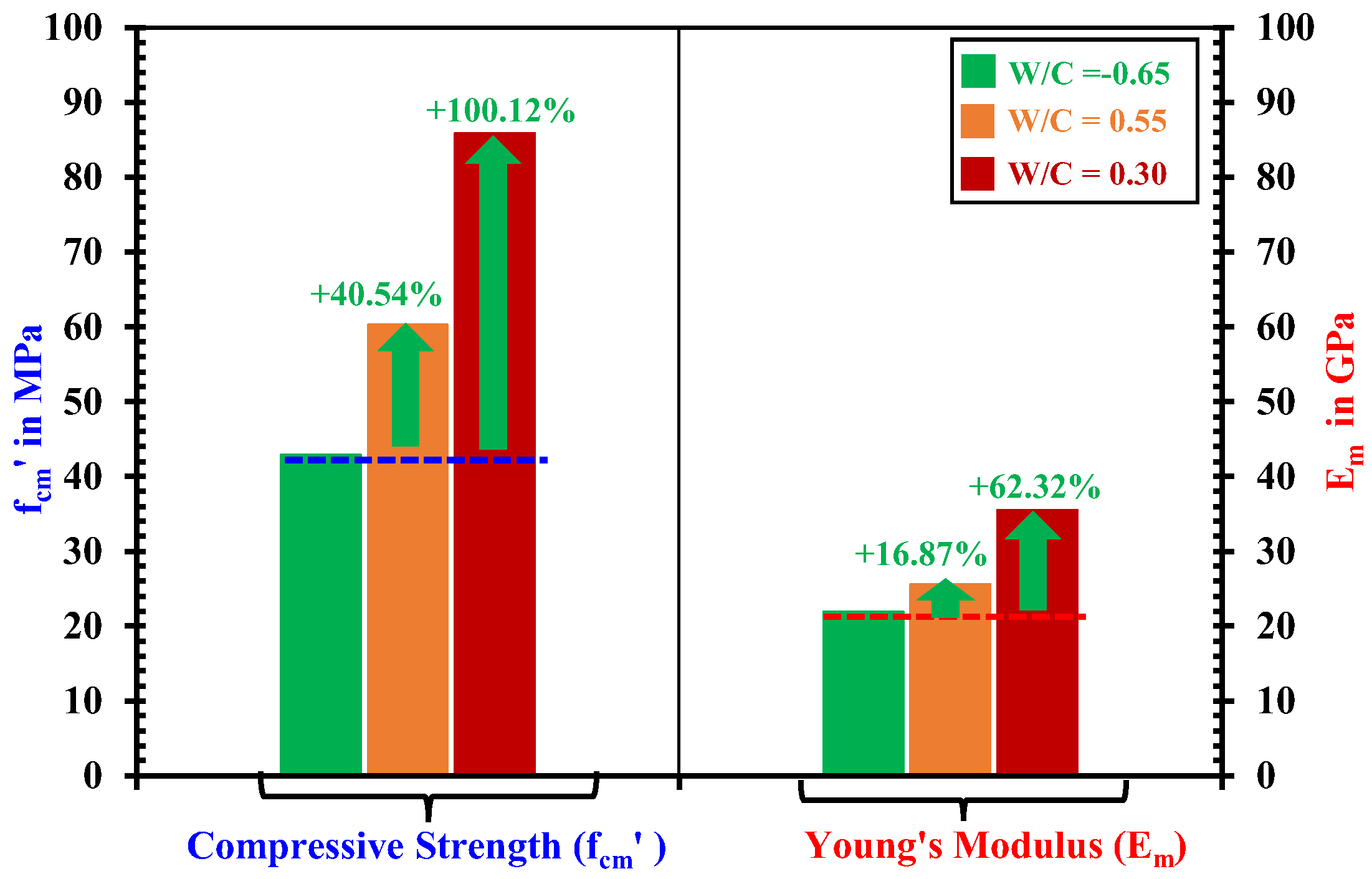
| Low | M-0.65-1 M-0.65-2 | 152.5 × 100.8 × 50.3 151.6 × 101.7 × 50.2 | 76 145 | 89 157 | 124 174 | 40.52 45.24 | 22.02 21.72 |
| Medium | M-0.55-1 M-0.55-2 | 151.4 × 102.4 × 50.2 152.6 × 102.1 × 50.6 | 78 145 | 102 157 | 124 174 | 61.33 59.21 | 26.08 25.04 |
| High | M-0.30-1 M-0.30-2 | 153.3 × 100.5 × 50.4 151.3 × 100.2 × 50.0 | 32 32 | 42 49 | 56 84 | 83.66 87.97 | 34.82 36.18 |
| Strength | Designation | x-axis Strains (%) at Position-1 (εxx-1) | x-axis Strains (%) at Position-2 (εxx-2) | ||||||
|---|---|---|---|---|---|---|---|---|---|
| 360 min | 1440 min | 2880 min | 9600 min | 360 min | 1440 min | 2880 min | 9600 min | ||
| Low | M-0.65-1 M-0.65-2 | 0.0233 0.0274 | 0.0395 0.0445 | 0.0448 0.0511 | 0.0495 0.0593 | 0.0017 0.0025 | 0.0117 0.0153 | 0.0226 0.0294 | 0.0386 0.0448 |
| Medium | M-0.55-1 M-0.55-2 | 0.0180 0.0130 | 0.0338 0.0261 | 0.0403 0.0322 | 0.0467 0.0378 | −0.0002 0.0005 | 0.0040 0.0025 | 0.0084 0.0054 | 0.0171 0.0148 |
| High | M-0.30-1 M-0.30-2 | 0.0095 0.0108 | 0.0187 0.0194 | 0.0217 0.0239 | 0.0293 0.0284 | 0.0003 −0.0001 | 0.0006 0.0003 | 0.0012 0.0010 | 0.0062 0.0040 |
| Strength | Designation | y-axis Strains (%) at Position-1 (εyy-1) | y-axis Strains (%) at Position-2 (εyy-2) | ||||||
|---|---|---|---|---|---|---|---|---|---|
| 360 min | 1440 min | 2880 min | 9600 min | 360 min | 1440 min | 2880 min | 9600 min | ||
| Low | M-0.65-1 M-0.65-2 | 0.0423 0.0411 | 0.0513 0.0488 | 0.0492 0.0476 | 0.0488 0.0491 | −0.0022 −0.0027 | −0.0072 −0.0071 | 0.0016 0.0016 | 0.0361 0.0522 |
| Medium | M-0.55-1 M-0.55-2 | 0.0175 0.0094 | 0.0412 0.0393 | 0.0420 0.0414 | 0.0427 0.0422 | −0.0011 −0.0007 | −0.0033 −0.0037 | −0.0031 −0.0045 | 0.0038 0.0046 |
| High | M-0.30-1 M-0.30-2 | −0.018 −0.009 | 0.0124 0.0293 | 0.030 0.0398 | 0.0383 0.0397 | 0.0006 −0.0006 | −0.0016 −0.0027 | −0.0032 −0.0040 | 0.0008 −0.0033 |
| Strength | Designation | By x-axis Gauge | By DICM Near x-axis Gauge | ||||||
|---|---|---|---|---|---|---|---|---|---|
| 360 min | 1440 min | 2880 min | 9600 min | 360 min | 1440 min | 2880 min | 9600 min | ||
| Low | M-0.65-1 M-0.65-2 | 0.0217 0.0256 | 0.0378 0.0432 | 0.0429 0.0510 | 0.0474 0.0619 | 0.0286 0.0287 | 0.0398 0.0437 | 0.0430 0.0489 | 0.0452 0.0596 |
| Medium | M-0.55-1 M-0.55-2 | 00165 0.0122 | 0.0304 0.0261 | 0.0360 0.0319 | 0.0395 0.0354 | 0.0120 0.0203 | 0.0313 0.0256 | 0.0409 0.0362 | 0.0490 0.0387 |
| High | M-0.30-1 M-0.30-2 | 0.008 0.0094 | 0.0161 0.0169 | 0.0185 0.0230 | 0.0243 0.0289 | 0.0093 0.0147 | 0.0203 0.0168 | 0.0221 0.0222 | 0.0242 0.0250 |
| Strength | Specimen | Water Absorption Depth (mm) | |||
|---|---|---|---|---|---|
| t = 360 min | t = 1440 min | t = 2880 min | t = 9600 min | ||
| Low | M-0.65-1 M-0.65-2 | 28.33 25.91 | 45.38 43.20 | 51.00 51.68 | 60.09 61.97 |
| Medium | M-0.55-1 M-0.55-2 | 21.11 19.63 | 32.24 32.05 | 39.29 43.01 | 48.68 54.21 |
| High | M-0.30-1 M-0.30-2 | 14.10 14.64 | 21.80 21.20 | 24.54 24.15 | 25.01 25.03 |
| Strength | Specimen | Depth Before Deviation (mm) | Rate of Absorptions (mm/min0.5) | |||
|---|---|---|---|---|---|---|
| I1 | R2 | I2 | R2 | |||
| Low | M-0.65-1 M-0.65-2 | 49.09 46.50 | 0.988 1.063 | 0.9568 0.9766 | 0.230 0.249 | 0.9043 0.8447 |
| Medium | M-0.55-1 M-0.55-2 | 34.02 47.22 | 0.699 0.733 | 0.9604 0.9867 | 0.197 0.133 | 0.9512 0.5776 |
| High | M-0.30-1 M-0.30-2 | 23.53 23.15 | 0.468 0.418 | 0.9729 0.9560 | 0.021 0.030 | 0.7336 0.7838 |
| Strength | Designation | Mechanical Properties | Water Absorption Characteristics by DICM | ||||
|---|---|---|---|---|---|---|---|
| f’cm (MPa) | Em (GPa) | I1 (mm/min0.5) | I2 (mm/min0.5) | Ɛxx-1 (2160) (%) | Ɛxx-1 (9600) (%) | ||
| Low | M-0.65-1 M-0.65-2 | 40.52 45.24 | 22.02 21.72 | 0.988 1.063 | 0.230 0.249 | 0.0429 0.0486 | 0.0452 0.0596 |
| Medium | M-0.55-1 M-0.55-2 | 61.33 59.21 | 26.08 25.04 | 0.699 0.733 | 0.197 0.133 | 0.0379 0.0296 | 0.0490 0.0387 |
| High | M-0.30-1 M-0.30-2 | 83.66 87.97 | 34.82 36.18 | 0.468 0.418 | 0.0211 0.0292 | 0.0203 0.0207 | 0.0242 0.0250 |
Disclaimer/Publisher’s Note: The statements, opinions and data contained in all publications are solely those of the individual author(s) and contributor(s) and not of MDPI and/or the editor(s). MDPI and/or the editor(s) disclaim responsibility for any injury to people or property resulting from any ideas, methods, instructions or products referred to in the content. |
© 2025 by the authors. Licensee MDPI, Basel, Switzerland. This article is an open access article distributed under the terms and conditions of the Creative Commons Attribution (CC BY) license (https://creativecommons.org/licenses/by/4.0/).
Share and Cite
Usman, M.; Nakamura, H.; Karam, M.S.; Miura, T.; Igarashi, G. Study on Relationship Between Mechanical Properties and Water Absorption Characteristics of Mortars by Using Digital Image Correlation Method (DICM). Materials 2025, 18, 1182. https://doi.org/10.3390/ma18051182
Usman M, Nakamura H, Karam MS, Miura T, Igarashi G. Study on Relationship Between Mechanical Properties and Water Absorption Characteristics of Mortars by Using Digital Image Correlation Method (DICM). Materials. 2025; 18(5):1182. https://doi.org/10.3390/ma18051182
Chicago/Turabian StyleUsman, Muhammad, Hikaru Nakamura, Muhammad Shoaib Karam, Taito Miura, and Go Igarashi. 2025. "Study on Relationship Between Mechanical Properties and Water Absorption Characteristics of Mortars by Using Digital Image Correlation Method (DICM)" Materials 18, no. 5: 1182. https://doi.org/10.3390/ma18051182
APA StyleUsman, M., Nakamura, H., Karam, M. S., Miura, T., & Igarashi, G. (2025). Study on Relationship Between Mechanical Properties and Water Absorption Characteristics of Mortars by Using Digital Image Correlation Method (DICM). Materials, 18(5), 1182. https://doi.org/10.3390/ma18051182