
The Effect of Thermal Processing on the Microstructure and Properties of a Novel Nickel-Based Powder Metallurgy Superalloy

 , ,
, ,
Abstract
1. Introduction
2. Materials and Methods
2.1. Materials
2.2. Performance Testing
2.3. Microstructure Observation
3. Results and Discussion
3.1. Microstructure
3.1.1. Grain Size
3.1.2. γ′ Phase
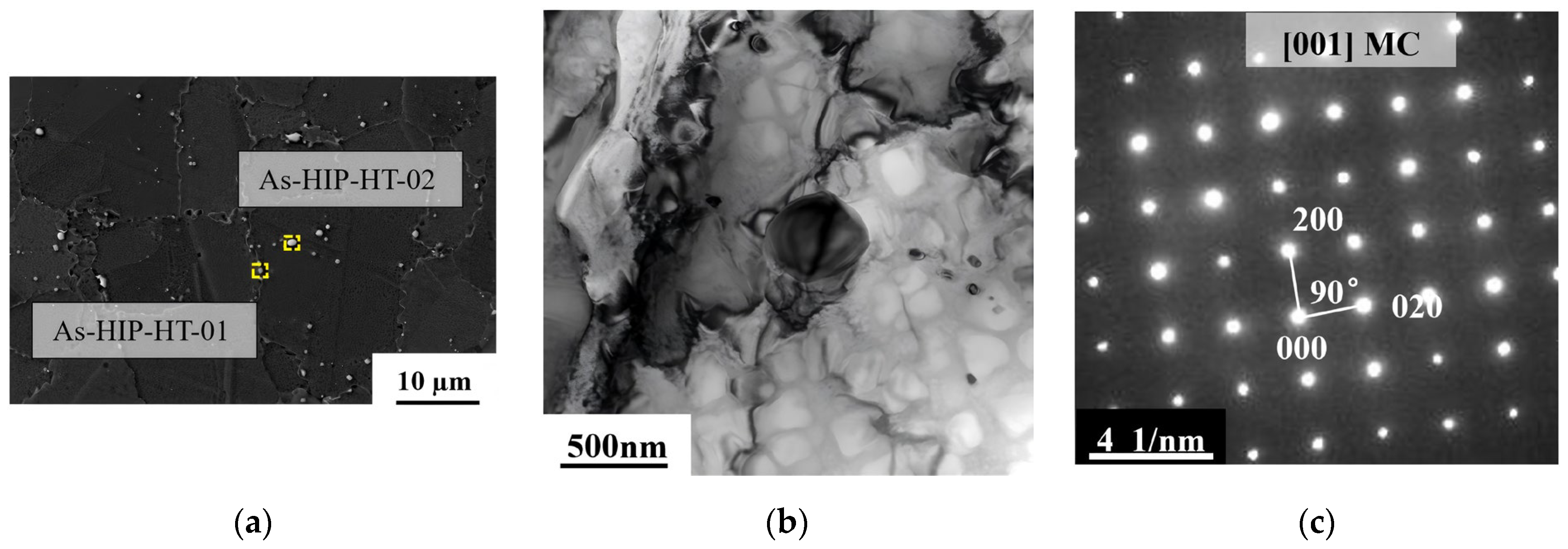
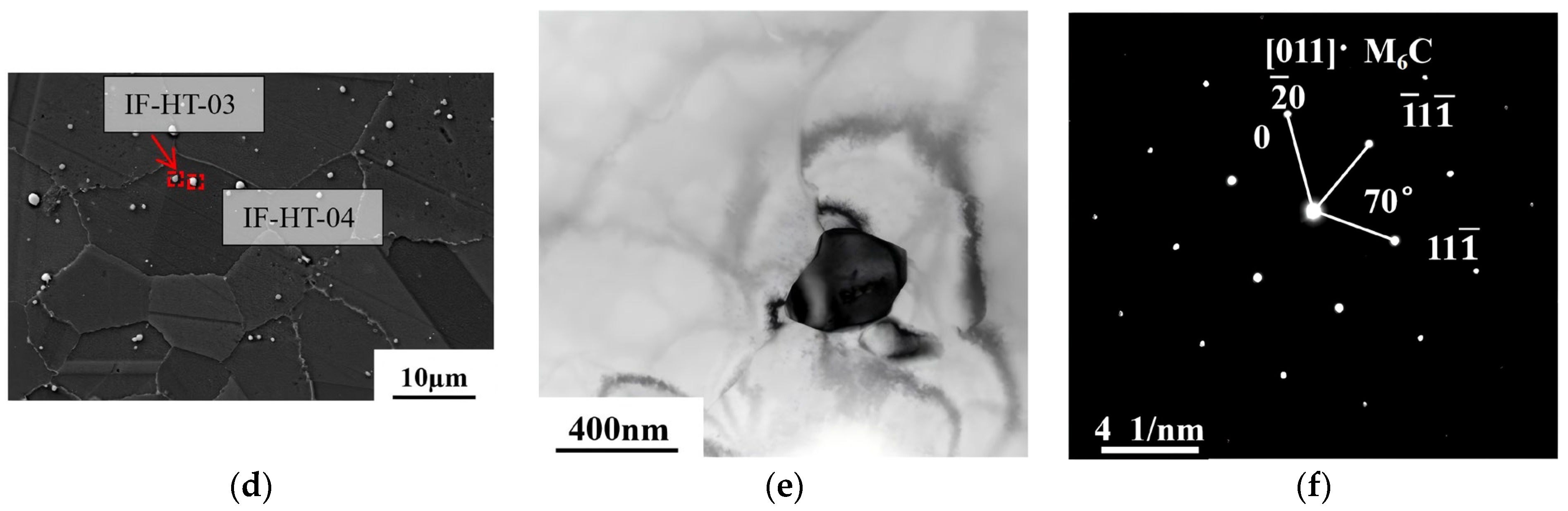
3.1.3. Carbides
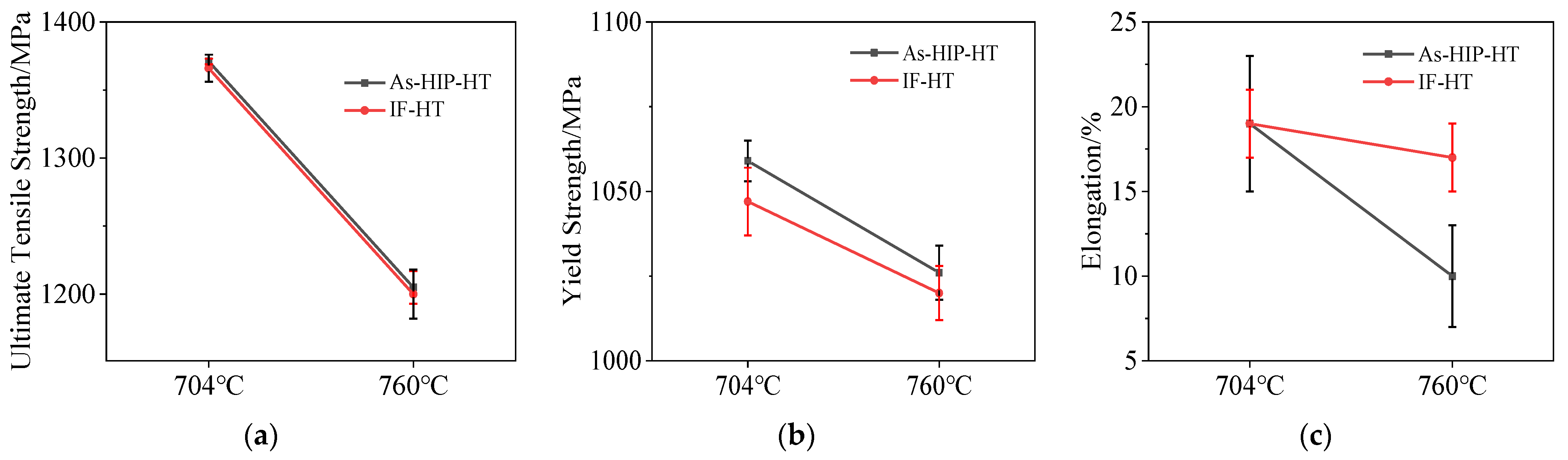
3.2. Tensile Properties
3.3. Creep Properties
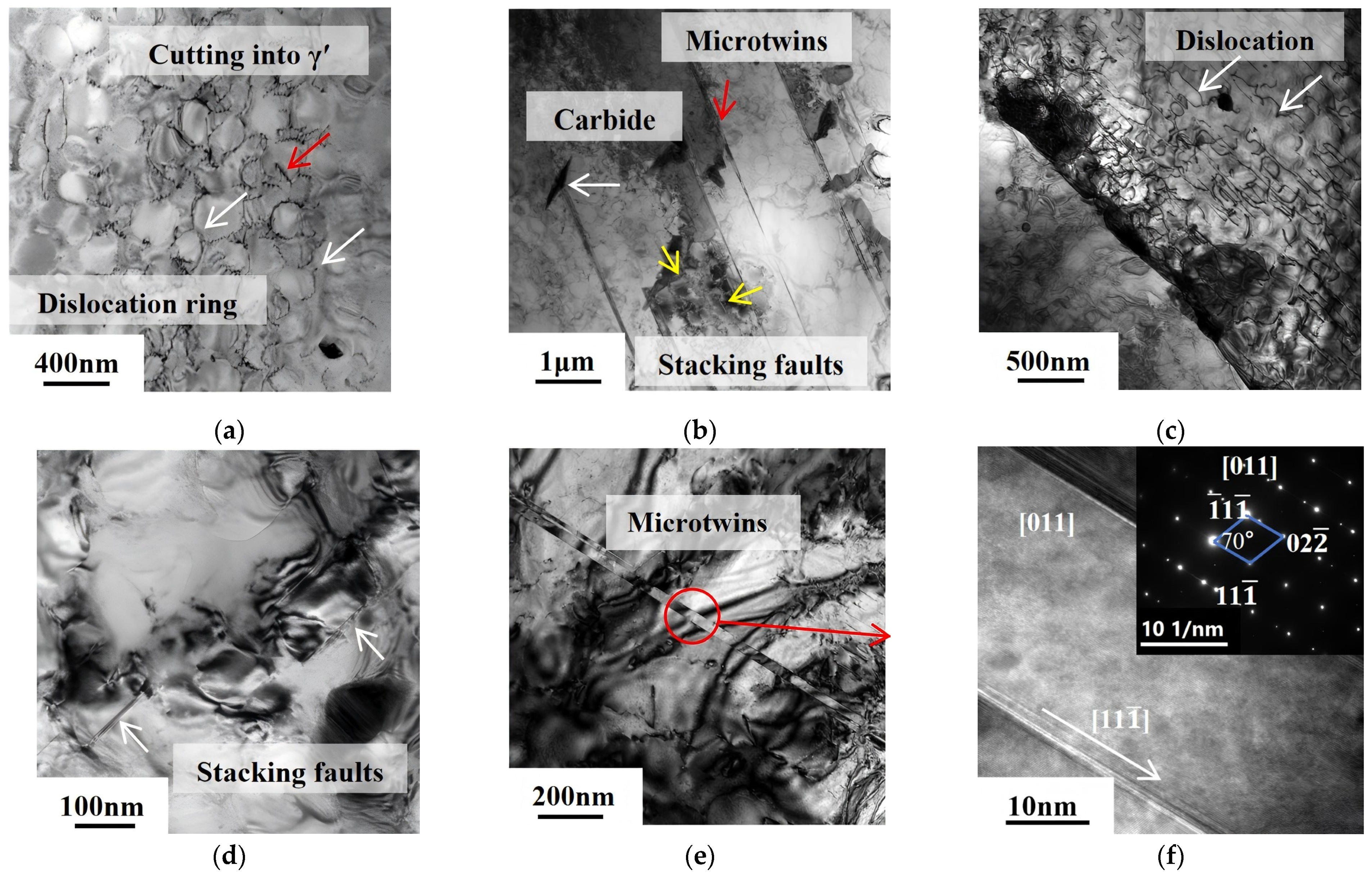
3.4. TEM Analysis of Microstructure near the Creep Fractures
4. Conclusions
- (1)
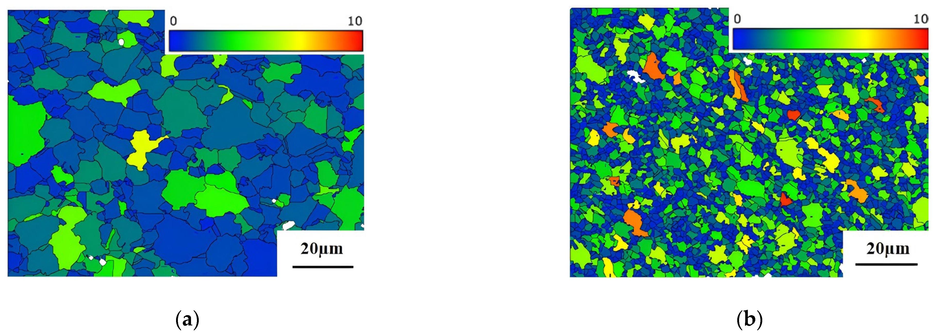
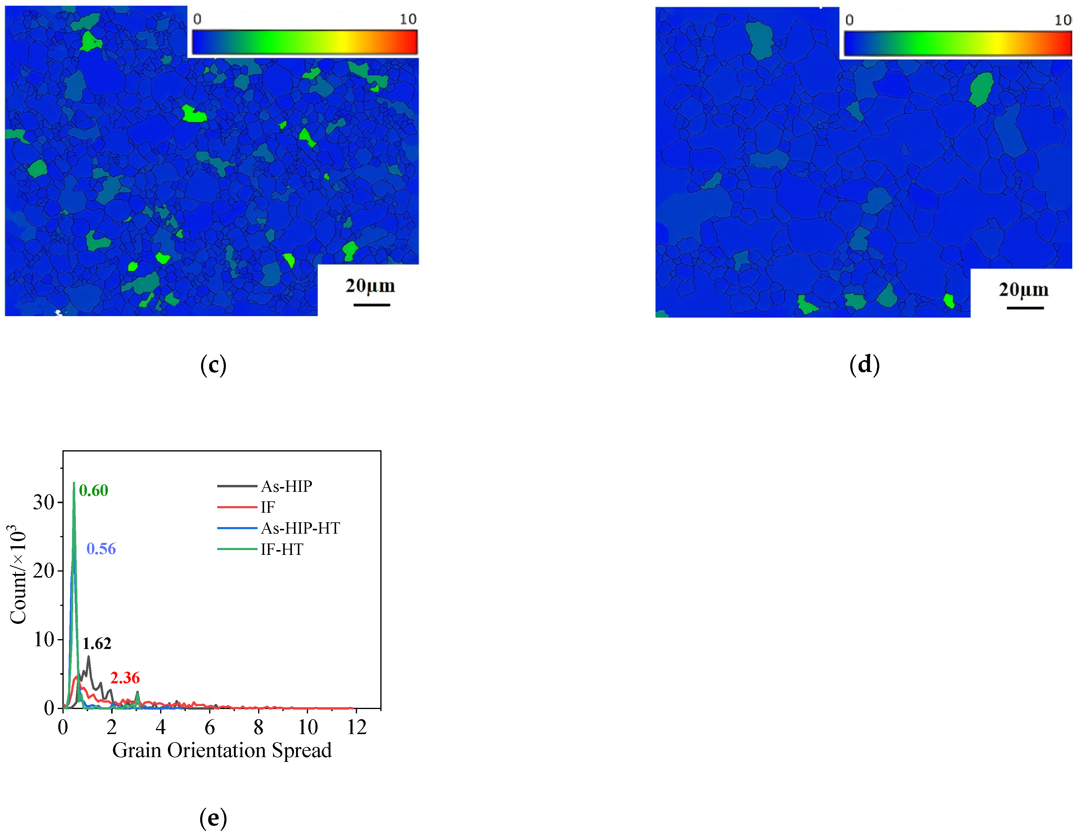
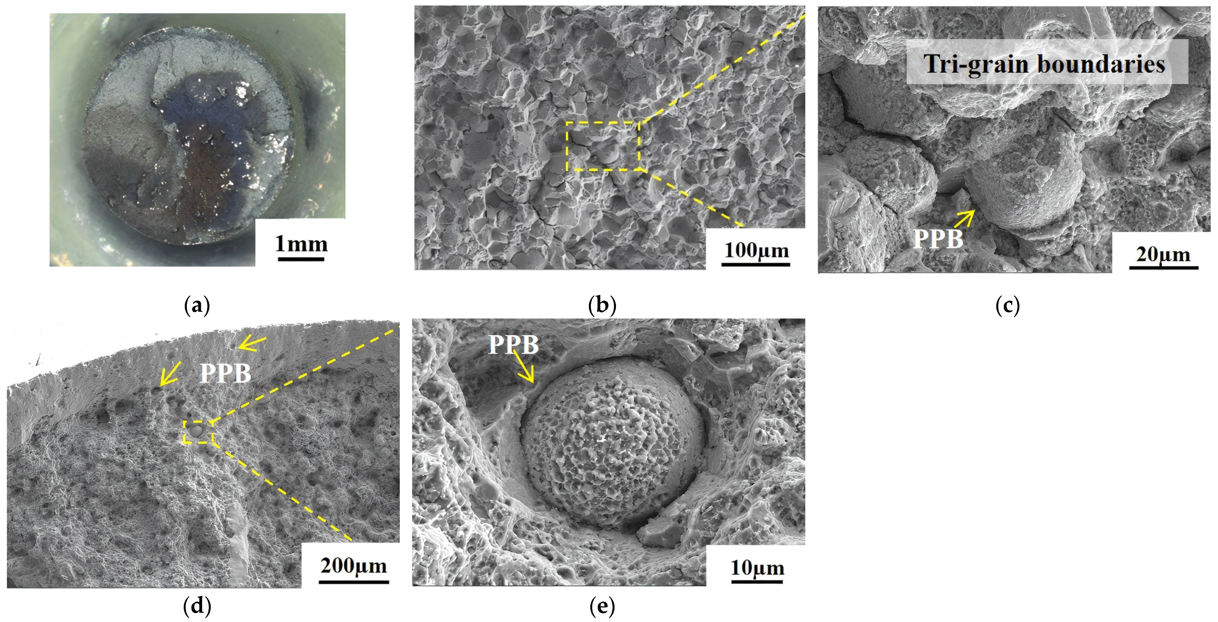
- Both the As-HIP and IF alloys underwent sufficient recrystallization, with average grain sizes of 12.7 μm (As-HIP) and 3.5 μm (IF). The As-HIP alloy exhibited distinct PPBs. The grain sizes significantly increased after HT for both the As-HIP-HT and IF-HT alloys. Due to higher storage energy, the grain size of the IF-HT state is larger than that of the As-HIP-HT alloy.
- (2)
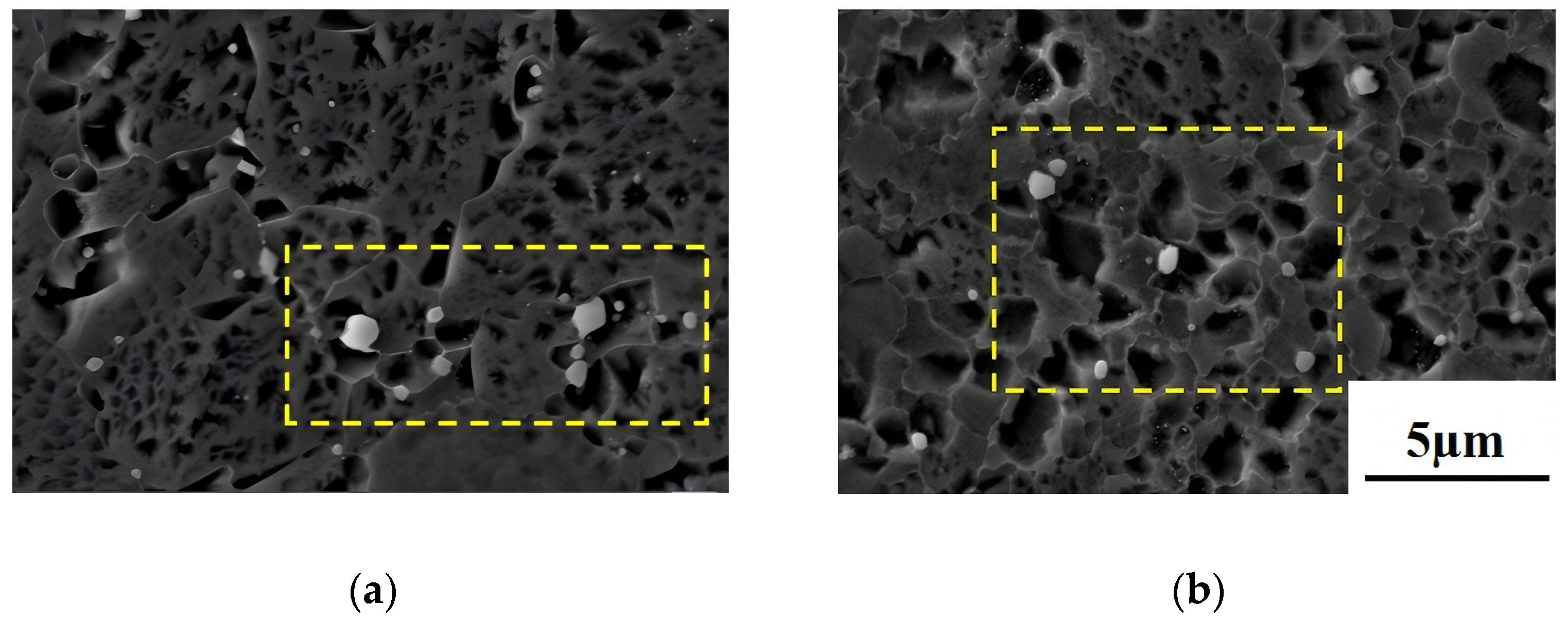
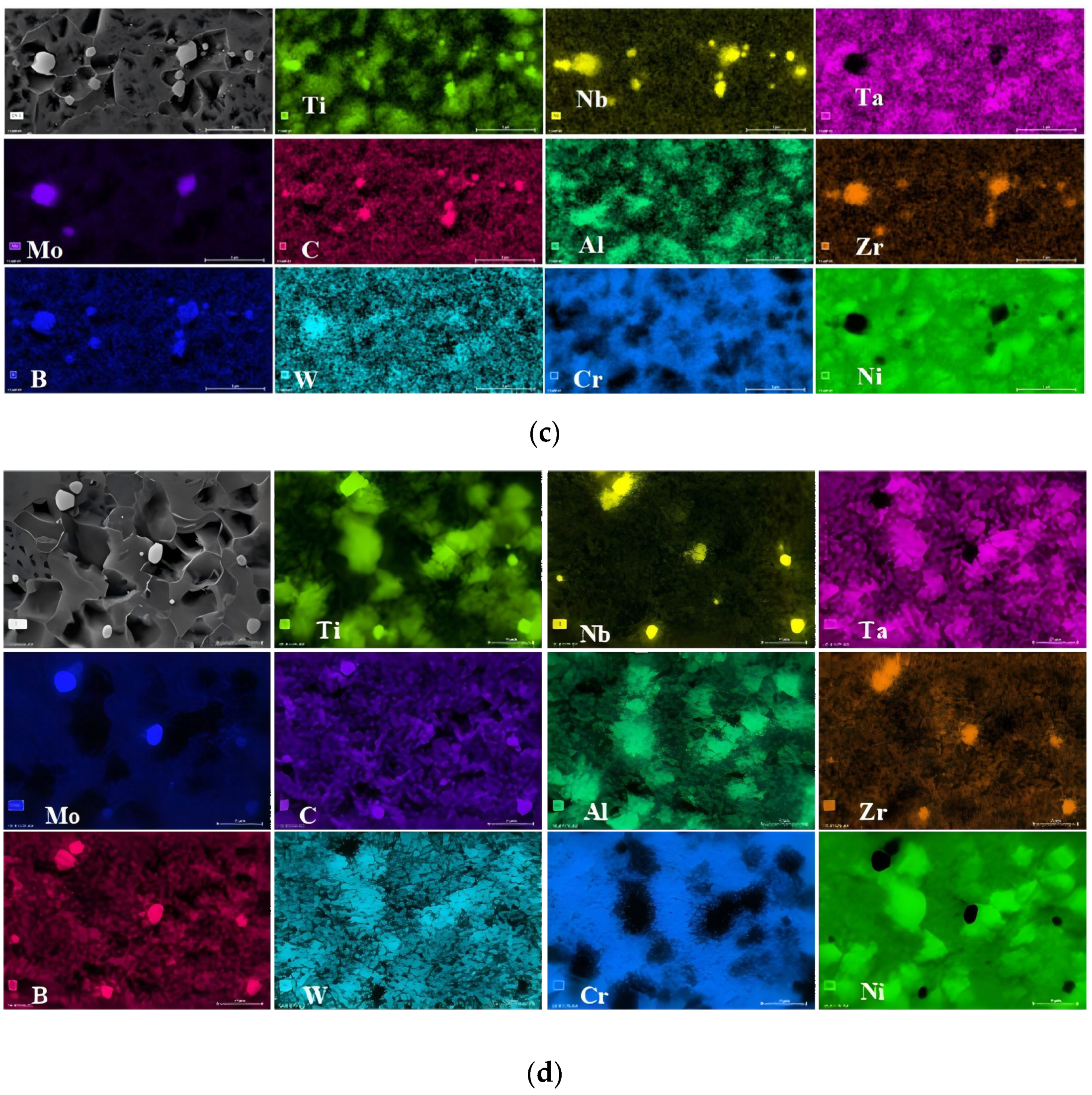
- In both the As-HIP-HT and IF-HT alloys, the primary γ′ precipitates completely dissolved, while significant differences in secondary γ′ were observed due to compositional non-uniformity in the substructure of the As-HIP state, resulting in a relatively long period for γ′ phase nucleation, leading to fewer, larger γ′ particles compared to the more uniform substructure of the IF state, which allowed for more numerous, smaller γ′ precipitates. Both states exhibited similar dispersed MC and M6C carbides pre- and post-HT.
- (3)
- At both 704 °C and 760 °C, the YS of the As-HIP-HT state was higher than that of the IF-HT alloy. The plasticity of the As-HIP-HT state alloy decreased sharply from 19% to 10% as the temperature rose, while the plasticity of the IF-HT state remained relatively unchanged. The presence of PPBs in the As-HIP-HT state had minimal impact on the alloy’s strength, but it did reduce the alloy’s plasticity to some extent.
- (4)
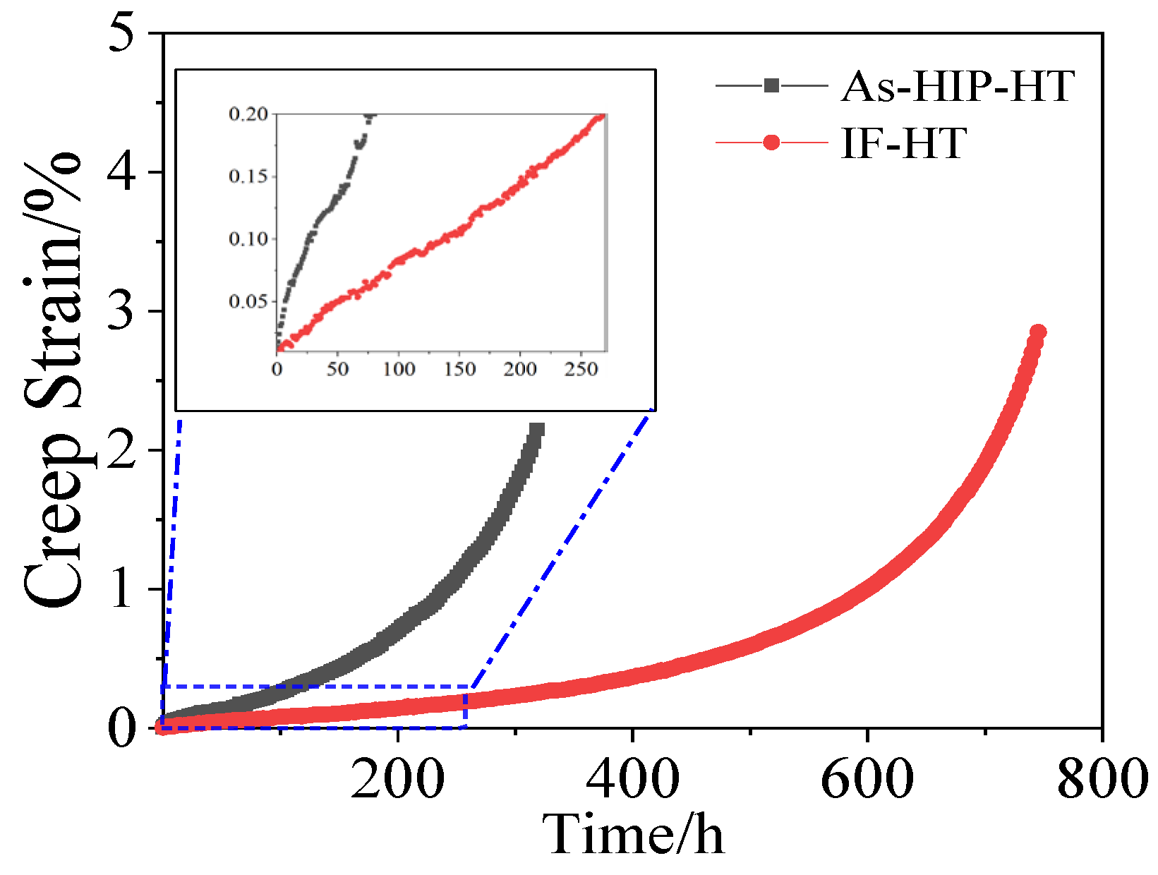
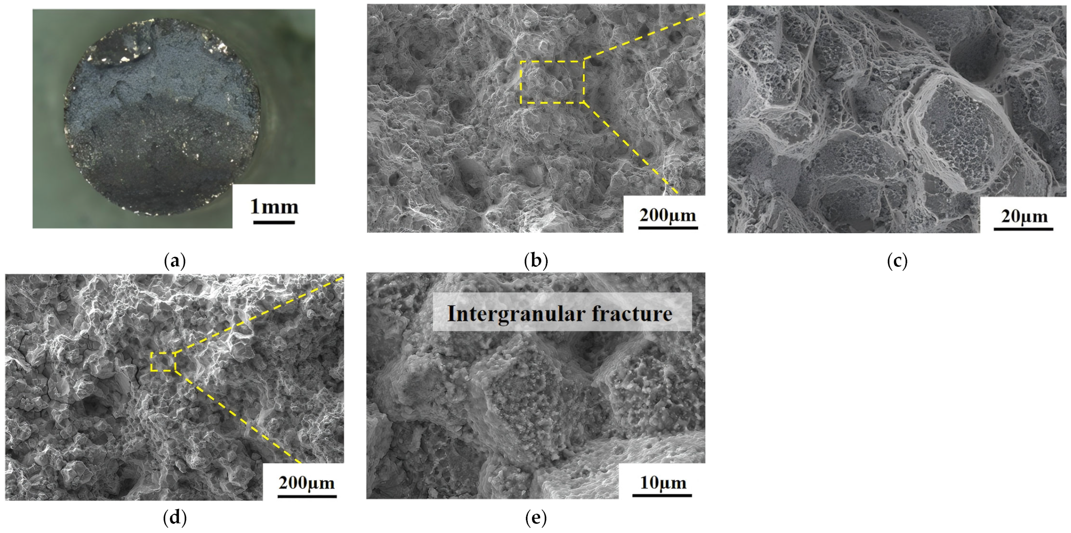
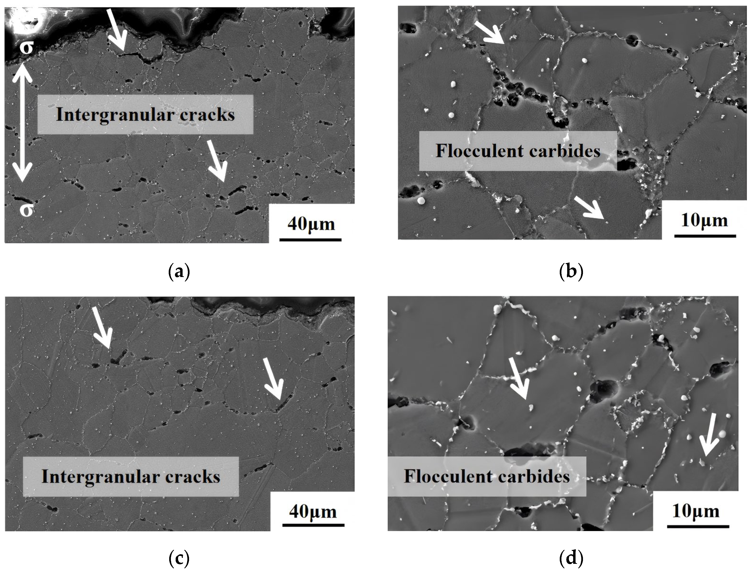
- Creep testing at 800 °C/330 MPa revealed a significant difference in creep life between the As-HIP-HT and IF-HT alloys. The IF-HT alloy exhibited lower creep rates and longer lifespans owing to its finer γ′ precipitate size. In the As-HIP-HT state, the primary mechanisms of creep deformation were Orawan dislocation loops and deformation twins. Conversely, in the IF-HT state, the main mechanisms were dislocations cutting through the γ′ phase, dislocation slip, and microtwins.
Author Contributions
Funding
Institutional Review Board Statement
Informed Consent Statement
Data Availability Statement
Conflicts of Interest
References
- Reed, R.C. The Superalloys: Fundamentals and Applications; Cambridge University Press: Cambridge, UK, 2010; pp. 1–10. [Google Scholar]
- Gabb, T.P.; Telesman, J.; Kantzos, P.T.; O′Connor, K. Characterization of the Temperature Capabilities of Advanced Disk Alloy ME3. J. NASA/TM-2002-211796; NASA: Cleveland, OH, USA, 2002; pp. 1–56. [Google Scholar]
- Detrois, M.; Rotella, J.; Goetz, R.L.; Helmink, R.C.; Tin, S. Grain boundary engineering of powder processed Ni-base superalloy RR1000 influence of the deformation parameters. Mater. Sci. Eng. A 2015, 627, 95–105. [Google Scholar] [CrossRef]
- Parr, I.M.; Jackson, T.J.; Hardy, M.C.; Child, D.J.; Argyrakis, C.; Severs, K.; Saraf, V.; Stumpf, J.M. Inhomogeneous grain coarsening behavior in supersolvus heat treated nickel-based superalloy RR1000. In Proceedings of the Superalloys 2016, Champion, PA, USA, 12–17 September 2004; pp. 447–456. [Google Scholar]
- Gabb, T.P.; Gayda, J.; Telesman, J. Thermal and Mechanical Property Characterization of the Advanced Disk Alloy LSHR. NASA/TM-2005-213645; NASA: Cleveland, OH, USA, 2005; pp. 1–82. [Google Scholar]
- Wu, K.; Liu, G.O.; Hu, B.F.; Zhang, Y.W.; Tao, Y.; Liu, J.T. Effect of solution heat treatment on the microstructure and properties of a novel nickel-based P/M superalloy FGH98I. Rare Metal Mat. Eng.(Chin. Ed.) 2010, 11, 1966–1970. [Google Scholar]
- Xiong, J.Y.; Yin, C.; Wang, C.; Guo, J.Z. Study on microstructure long-term stability of powder metallurgy superalloy FGH4113A. Rare Metal Mat. Eng. (Chin. Ed.) 2023, 52, 2885–2892. [Google Scholar] [CrossRef]
- Yang, J.L.; Long, A.P.; Zhang, G.X.; Guo, J.Z. The microstructure and properties of a novel nickel-based P/M superalloy. Rare Metal Mat. Eng. (Chin. Ed.) 2022, 51, 1031–1039. [Google Scholar]
- Xiong, J.Y.; Yin, C.; Wang, C.; Feng, G.J.; Guo, J.Z. The effect of long-term aging on the microstructure and properties of a novel nickel-based powder superalloy FGH4113A. Materials 2024, 17, 4175. [Google Scholar] [CrossRef]
- Yang, J.L.; Cui, J.Y.; Cheng, J.Y.; Yin, C.; Guo, J.Z.; Feng, G.J. Hot deformation behavior and microstructure evolution of a novel nickel-based powder metallurgy superalloy. J. Mater. Res. Technol. 2023, 27, 7347–7363. [Google Scholar] [CrossRef]
- Zhang, Y.W.; Chi, Y.; Liu, J.T. Recent development of new type powder metallurgy superalloys in Russia. Power Metall. Industry. (Chin. Ed.) 2015, 25, 1–14. [Google Scholar] [CrossRef]
- Zhang, Y.W.; Jia, J.; Liu, J.T.; Qu, J.L. Recent development of new type powder metallurgy superalloys in Russia. Power Metall. Industry. (Chin. Ed.) 2020, 30, 102–116. [Google Scholar] [CrossRef]
- Liu, J.T.; Tao, Y.; Zhang, Y.W.; Zhang, G.X. Microstructure and mechanical property of FGH96 alloy dual property disk. Trans. Meter. Heat Treat. (Chin. Ed.) 2010, 31, 71–74. [Google Scholar]
- Zhang, Y.W.; Liu, J.T.; Jia, J.; Zhang, Y. Effect of cooling rates of hot isostatic pressing process on P/M superalloy. Power Metall. Industry. (Chin. Ed.) 2010, 20, 11–17. [Google Scholar] [CrossRef]
- Liu, Y.F.; Liu, N.; Zheng, L.; Xu, W.Y.; Liu, Y.; Yuan, H. Effect of HIPing temperatures and powders particle size on microstructure and properties of PM TiAl alloy. Rare Metal Mat. Eng. 2019, 48, 3227–3233. [Google Scholar]
- May, J.R.; Hardy, M.C.; Bache, M.P.; Kaylor, D.D. Microstructure and mechanical properties of an advanced nickel-based superalloy in the as-HIP form. Adv. Mater. Res. 2011, 278, 265–270. [Google Scholar] [CrossRef]
- Rao, G.A.; Satyanarayana, D.V.V. Influence of HIP processing on microstructure and mechanical properties of superalloy Udimet 720LI. J. Mater. Sci. Technol. 2013, 27, 478–486. [Google Scholar] [CrossRef]
- Ning, Y.Q.; Yao, Z.K.; Guo, H.Z.; Tao, Y.; Zhang, Y.W. Fundamental investigation on preparation of ultrafine-grained billet for dual-property turbine disc. Rare Metal Mat. Eng. (Chin. Ed.) 2010, 39, 1235–1239. [Google Scholar]
- Peng, Z.C.; Liu, P.Y.; Wang, X.Q.; Luo, X.J.; Liu, J.; Zou, J.W. Creep behavior of FGH96 superalloy at different service conditions. Acta Metall. Sin. (Chin. Ed.) 2022, 58, 673–682. [Google Scholar] [CrossRef]
- Xiao, L.; He, Y.J.; Ma, X.D.; Qiu, C.R.; Yang, J.L.; Guo, J.Z. Extrusion test study on a novel nickel-based Powder metallurgy Superalloy. J. Rare Metal Mat. Eng. (Chin. Ed.) 2022, 51, 2215–2223. [Google Scholar] [CrossRef]
- Li, Y.; He, Y.J.; Cui, J.Y.; Ma, X.D.; Guo, J.Z. Microstructure evolution of an as-extruded WZ-A3 alloy during isothermal forging. J. Mater. Sci. 2022, 57, 8329–8347. [Google Scholar] [CrossRef]
- Tian, T.; Hao, Z.B.; Jia, C.L.; Ge, C.C. Microstructure and properties of a new third generation powder metallurgy superalloy FGH100L. Acta Metall. Sinica. (Chin. Ed.) 2019, 55, 1260–1272. [Google Scholar]
- Wu, H.; Liu, M.X.; Wang, Y.; Huang, Z.Q.; Tan, G.; Yang, L. Experimental study and numerical simulation of dynamic recrystallization for a FGH96 superalloy during isothermal compression. J. Mater. Res. Technol. 2020, 9, 5090–5104. [Google Scholar] [CrossRef]
- Hu, B.F.; Chen, H.M.; Jin, K.S.; Li, H.Y. Static recrystallization mechanism of FGH95 superalloy. Chin. J. Nonferrous. Met. (Chin. Ed.) 2004, 14, 901–906. [Google Scholar]
- Liu, J.T.; Zhang, Y.W.; Tao, Y.; Liu, G.Q.; Hu, B.F. Grain growth behavior of FGH96 power metallurgy superalloys billet disc during heat treatment. Metall. Heat Treat. (Chin. Ed.) 2006, 31, 40–44. [Google Scholar]
- Agnoli, A.; Bernacki, M.; Logé, R.; Franchet, J.M.; Laigo, J.; Bozzolo, N. Selective growth of low stored energy grains during δ sub-solvus annealing in the inconel 718 nickel-based superalloy. Metall. Mater. Trans. A 2015, 46, 4405–4421. [Google Scholar] [CrossRef]
- Yin, F.Z.; Hu, B.F.; Jin, K.S.; Jia, C.C. Effect of hot extrusion and heat treatment on the γ′ phase precipitation in FGH95 alloy. J. Mater. Eng. (Chin. Ed.) 2005, 10, 52–55. [Google Scholar]
- Ning, Y.Q.; Zhou, C.; Liang, H.Q.; Fu, M.W. Abnormal flow behavior and necklace microstructure of powder metallurgy superalloys with previous particle boundaries (PPBs). Mater. Sci. Eng. A. 2016, 652, 84–91. [Google Scholar] [CrossRef]
- Zeng, Y.; Bu, H.Y.; Li, P.K.; Wang, C.; Li, S.H. Effect of interrupted cooling on microstructural evolution and microhardness of FGH97 nickel-based PM superalloy. Mater. Des. 2024, 241, 112924. [Google Scholar] [CrossRef]
- Yıldız, G.; Gursel, A.; Akca, E. Effects of Cooling Rate on Strength and Microstructure of Powder Metallurgy Superalloys. Per. Eng. Nat. Sci. 2017, 5, 251–255. [Google Scholar]
- Hu, P.H.; Liu, G.Q.; Hu, B.F.; Ma, W.B.; Zhang, Y.W.; Liu, J.T. Characteristics of rapidly solidified powder particles in Hf-modified nickel-based P/M superalloys. J. Univ. Sci. Technol. Beijing. (Chin. Ed.) 2013, 35, 1174–1180. [Google Scholar] [CrossRef]
- Yuan, H.; Li, Z.; Xu, W.Y.; Zhang, G.Q. The study of argon atomized superalloy powers. Power Metall. Industry. (Chin. Ed.) 2010, 20, 1–5. [Google Scholar]
- Campbell, C.E.; Boettinger, W.J.; Kattner, U.P. Development of a diffusion mobility database for Ni-base superalloys. Acta Mater. 2002, 50, 775–792. [Google Scholar] [CrossRef]
- Zhang, Y.; Zhang, Y.W.; Sun, Z.K.; Huang, H.B. Influence of PPB on crack growth behavior of PM Ni-based superalloy. Rare Metal Mat. Eng. (Chin. Ed.) 2019, 48, 3282–3288. [Google Scholar]
- Xia, T.; Zhang, Y.W.; Chi, Y. The influence of Hf and Zr on PPB and properties of FGH96. Power Metall. Technol. 2013, 31, 53–61. [Google Scholar] [CrossRef]
- Xiong, J.Y.; Long, A.P.; Xiao, L.; Yang, J.L. Microstructure and properties of argon atomization FGH4097 alloy high-pressure turbine disc. Hot Working Technol.(Chin. Ed.) 2022, 51, 22–27. [Google Scholar] [CrossRef]
- Tian, N.; Tian, S.G.; Yu, H.C.; Meng, X.L. Influence of solution temperature on intermediate-temperature creep property of a directionally solidified nickel-base superalloy. Trans. Mater. Heat Treat. (Chin. Ed.) 2014, 35, 86–93. [Google Scholar]
- Décamps, B.; Morton, A.J.; Condat, M. On the mechanism of shear of γ′ precipitates by single (a/2)110 dissociated matrix dislocations in Ni-based superalloys. Philos. Mag. A 1991, 64, 641–668. [Google Scholar] [CrossRef]
- Décamps, B.; Raujol, S.; Coujou, A.; Pettinari-Sturmel, F.; Clément, N.; Locq, D.; Caron, P. On the shearing mechanism of γ′ precipitates by a single (a/6)112 Shockley partial in Ni-based superalloys. Philos. Mag. 2004, 84, 91–107. [Google Scholar] [CrossRef]
- Peng, Z.C.; Zou, J.W.; Wang, X.Q. Microstructural characterization of dislocation movement during creep in powder metallurgy FGH96 superalloy. Mater. Today Commun. 2020, 25, 101361. [Google Scholar] [CrossRef]
- Peng, Z.C.; Tian, G.F.; Jiang, J.; Li, M.Z.; Chen, Y.; Zou, J.W.; Dunne, F.P.E. Mechanistic behaviour and modelling of creep in powder metallurgy FGH96 nickel superalloy. Mater. Sci. Eng. A. 2016, 676, 441–449. [Google Scholar] [CrossRef]
- Liu, L.R.; Jin, T.; Zhao, N.R.; Sun, X.F.; Guan, H.R.; Hu, Z.Q. Formation of carbides and their effects on stress rupture of a Ni-base single crystal superalloy. Mater. Sci. Eng. A 2003, 361, 191–197. [Google Scholar] [CrossRef]
- Peng, Z.C.; Zou, J.W.; Wang, Y.; Zhou, L.; Tang, Y. Effects of solution temperatures on creep resistance in a powder metallurgy nickel-based superalloy. Mater. Today Commun. 2021, 28, 102573. [Google Scholar] [CrossRef]


| Spectrum | Al | Ti | Cr | Co | Ni | Zr | Nb | Mo | Hf | Ta | W | Al + Ti + Ta + Nb | W + Mo |
|---|---|---|---|---|---|---|---|---|---|---|---|---|---|
| As-HIP-HT-01 | 0.4 | 3.6 | 17.6 | 7.4 | 15.3 | 0.8 | 2.9 | 26.0 | 0.1 | 1.6 | 24.3 | 8.5 | 50.4 |
| As-HIP-HT-02 | 1.7 | 12.8 | 10.5 | 13.5 | 30.2 | 1.0 | 9.8 | 3.6 | 2.9 | 10.8 | 3.3 | 35.1 | 6.8 |
| IF-HT-03 | 0.4 | 3.2 | 17.6 | 5.5 | 9.9 | 1.4 | 3.4 | 29.9 | 0.2 | 1.6 | 26.9 | 8.6 | 56.8 |
| IF-HT-04 | 1.2 | 18.4 | 6.2 | 8.6 | 20.8 | 1.3 | 15.6 | 3.0 | 3.3 | 18.4 | 3.1 | 53.6 | 6.1 |
Disclaimer/Publisher’s Note: The statements, opinions and data contained in all publications are solely those of the individual author(s) and contributor(s) and not of MDPI and/or the editor(s). MDPI and/or the editor(s) disclaim responsibility for any injury to people or property resulting from any ideas, methods, instructions or products referred to in the content. |
© 2025 by the authors. Licensee MDPI, Basel, Switzerland. This article is an open access article distributed under the terms and conditions of the Creative Commons Attribution (CC BY) license (https://creativecommons.org/licenses/by/4.0/).
Share and Cite
Xiong, J.; Yin, C.; Long, A.; Cheng, J.; Feng, G.; Guo, J. The Effect of Thermal Processing on the Microstructure and Properties of a Novel Nickel-Based Powder Metallurgy Superalloy. Materials 2025, 18, 1018. https://doi.org/10.3390/ma18051018
Xiong J, Yin C, Long A, Cheng J, Feng G, Guo J. The Effect of Thermal Processing on the Microstructure and Properties of a Novel Nickel-Based Powder Metallurgy Superalloy. Materials. 2025; 18(5):1018. https://doi.org/10.3390/ma18051018
Chicago/Turabian StyleXiong, Jiangying, Chao Yin, Anping Long, Junyi Cheng, Ganjiang Feng, and Jianzheng Guo. 2025. "The Effect of Thermal Processing on the Microstructure and Properties of a Novel Nickel-Based Powder Metallurgy Superalloy" Materials 18, no. 5: 1018. https://doi.org/10.3390/ma18051018
APA StyleXiong, J., Yin, C., Long, A., Cheng, J., Feng, G., & Guo, J. (2025). The Effect of Thermal Processing on the Microstructure and Properties of a Novel Nickel-Based Powder Metallurgy Superalloy. Materials, 18(5), 1018. https://doi.org/10.3390/ma18051018