1. Introduction
In recent years, with increasing governmental advocacy and support for green building initiatives, low-carbon, environmentally friendly, and sustainable development principles have become pivotal in modern design and construction practices. Against this backdrop, concrete-filled steel tube (CFST) structures have emerged as an innovative solution that seamlessly integrates the strengths of both concrete and steel, offering superior load-bearing capacities and exceptional ductility. Compared to structures composed solely of steel or concrete, CFST systems exhibit significantly enhanced load-bearing performance, often exceeding the combined strength of their constituent materials [
1,
2,
3]. This structural form [
4,
5,
6] excels in resisting complex load scenarios and demonstrates remarkable mechanical performance and durability under extreme environmental conditions such as earthquakes [
7,
8] and tsunamis. These attributes not only ensure the stability and integrity of building structures but also significantly extend their service life, underscoring the potential of CFST structures in sustainable construction.
Traditional CFST columns commonly feature rectangular, square, or circular cross-sections, as illustrated in
Figure 1 [
9]. These conventional cross-sectional forms are extensively utilized in construction due to their simplicity and efficiency. However, they also present certain limitations in practical applications, such as large volumes, construction constraints, and challenges associated with protruding corners. These issues can hinder the realization of flexible spatial layouts, particularly in spaces with unique or irregular configurations. To address these challenges, uniquely shaped CFST columns have been developed. With their adaptable design characteristics, these columns offer versatile solutions that cater to diverse building structures and spatial layouts, especially in architecturally unconventional or irregular spaces. Additionally, their distinctive forms contribute to a sense of modernity and artistic appeal, enhancing the overall aesthetic value of the building. Commonly used uniquely shaped CFST columns in contemporary construction include T-shaped, cross-shaped, and other specialized configurations, which have proven effective in balancing functional and aesthetic considerations.
Despite the numerous advantages of irregular CFST columns, there are still some challenges, such as thin column limbs, excessive aspect ratios, stress concentration at the corners, and the weak constraint effects of the steel tube on the core concrete. To address these issues, several scholars have proposed improvements to optimize the design of irregular columns. To enhance the performance of traditional T-shaped CFST columns, Tu et al. [
10] introduced a multi-unit T-shaped CFST (MT-CFST) column structure. Their study involved experimental tests on 13 short specimens with various cross-sectional shapes and material properties, as well as 12 slender specimens with different length-to-thickness ratios under an axial load. The study comprehensively explored the mechanical behavior of the multi-unit T-shaped CFST columns, focusing on the failure modes of short specimens, the relationship between the axial load and strain, and the axial load-bending curves of slender specimens. Liu et al. [
11] conducted axial compression tests on L-shaped and T-shaped CFST columns to investigate the mechanical performance of uniquely shaped CFST short columns. During the experiments, detailed observations were conducted on the specimens’ behavior and failure modes. The results showed that reinforcement ribs effectively delayed the local buckling of the steel tube, significantly improving the tube’s buckling load-bearing capacity and enhancing its constraint effect on the concrete. Liu et al. [
12] designed and fabricated 11 L-shaped multi-unit CFST short columns for axial compression tests, exploring the effects of the column side plate width-to-thickness ratio and concrete compressive strength on the failure mode, load-bearing capacity, and ductility of the specimens. The test results indicated that multi-core steel tubes significantly improved the constraint effect on the concrete. As the width-to-thickness ratio of the column side plates increased, the ductility gradually decreased. Moreover, increasing the compressive strength of the concrete enhanced the load-bearing capacity of the specimens but reduced their ductility. Hasan et al. [
13] conducted axial compression tests on three half-scale cross-shaped CFST columns, evaluating their failure modes, stress, displacement, and ductility. They also proposed a method to determine the maximum load-bearing capacity of cross-shaped CFST columns. This method provides guidance for the design of irregular cross-shaped CFST columns based on different seismic fortification requirements.
L-shaped CFST columns have gained attention due to their unique structural geometry, which enhances their adaptability to diverse spatial layouts and makes them particularly suitable for complex architectural designs. Although preliminary investigations into the mechanical behavior of L-shaped CFST columns have been conducted in recent years, several critical findings have emerged. Han et al. [
14] performed quasi-static tests to analyze how the geometric dimensions and steel tube configurations affect the seismic performance, revealing the critical role of the web thickness-to-flange length ratios in the energy dissipation capacity. Through parametric studies, Liu et al. [
11] demonstrated that controlling the steel plate width-to-thickness ratio and core concrete compressive strength could significantly improve the ultimate bearing capacity and ductility coefficients. Du et al. [
15] further validated the enhanced ductility of multi-cavity designs by establishing a trilinear skeleton curve model considering the slenderness ratio and axial compression ratio coupling effects, based on cyclic loading tests of nine L-shaped CFST specimens. However, existing research predominantly focuses on macroscopic parameter optimization and global response analysis. The refined design of internal stiffener configurations—including the quantity, layout patterns, and perforation parameters—and their influence on the localized stress distribution and buckling suppression mechanisms remain to be fully revealed. This knowledge gap limits the engineering application of such components in complex loading scenarios.
Therefore, this study proposes a novel L-shaped CFST column design featuring internal support plates to address challenges such as stress concentration and local buckling. Using the ABAQUS finite element software, nine L-shaped CFST column models were developed and analyzed to obtain load–displacement curves. The study systematically investigated the effects of the steel tube thickness, the number and configuration of internal support plates, the perforation settings, and the presence of holes on the compressive performance of the columns. Furthermore, the stress distribution of the support plates at the maximum displacement of the column ends was examined to provide insights into their contribution to the structural behavior. This research aims to advance the understanding and optimization of L-shaped CFST columns, contributing to their broader application in engineering practice.
5. Parametric Analysis
5.1. Steel Strength
The steel grades used in the models CFST-M-1, CFST-M-2, and CFST-M-3 are Q235B, Q345B, and Q420B, respectively, with all other simulation parameters kept constant, as detailed in
Table 2. The corresponding load–displacement curves are presented in
Figure 16. During the elastic stage, the initial stiffness of all specimens is nearly identical. However, the CFST-M-1 model, with the lowest steel strength, transitions to the elastoplastic stage earlier. All three models exhibit excellent compressive performance, characterized by a notable decline in load-bearing capacity after reaching the ultimate load. The CFST-M-1 model shows a more significant post-peak capacity reduction, with an average post-peak bearing capacity of approximately 58.3% of its ultimate load. In contrast, the CFST-M-2 and CFST-M-3 models maintain higher post-peak bearing capacities of around 65.2% and 67.3%, respectively. These results demonstrate the positive correlation between the steel strength and the compressive performance of irregular L-shaped CFST columns beyond their ultimate load.
Comparing the models, the ultimate bearing capacity of the CFST-M-2 model increased by approximately 8.5% relative to CFST-M-1, while the CFST-M-3 model achieved an increase of about 12.6%. Additionally, the bearing capacity enhancement factor (
δ) in
Table 2 reveals a consistent upward trend with increasing steel strength. This trend highlights the role of higher-strength steel in enhancing the confinement effect on the core concrete, thereby improving the compressive bearing capacity of the L-shaped CFST columns.
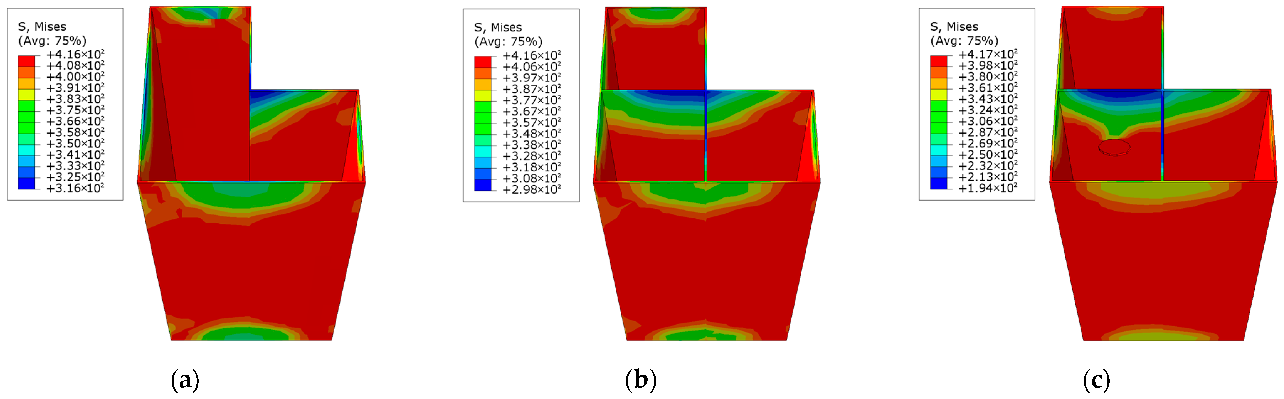
Figure 17 illustrates the stress distribution of the steel tube in the L-shaped CFST columns at the maximum displacement for different steel strengths. In the CFST-M-1 model, which utilizes the lowest-strength steel, the stress distribution is highly uneven, with significant stress concentration in the concave corner of the L-shaped column. This uneven distribution increases the likelihood of localized buckling in the steel tube, potentially leading to premature structural failure. Conversely, the CFST-M-2 and CFST-M-3 models, which employ higher-strength steels, exhibit more uniform stress distributions. Although the highest stress remains concentrated in the concave corner, the stresses in other regions are also elevated, resulting in a more balanced loading state. This uniform stress distribution facilitates the coordinated expansion of the steel tube and the encased concrete, enhancing the structural integrity of the columns. The use of higher-strength steel effectively mitigates localized buckling in the concave corner, improving the overall stability and performance of the L-shaped CFST columns under maximum displacement conditions.
In
Table 2,
Nu is the nominal load-bearing capacity, and
Nu =
fyAs +
fckAc, where
fy is the yield strength of the steel and
As is the cross-sectional area of the steel tube;
fck is the characteristic compressive strength of concrete;
Ac is the cross-sectional area of the concrete column; and
δ is the load-bearing capacity enhancement factor of the CFST column, where
δ =
(Nu −
Num)/Nu, and
Num is the simulated ultimate load capacity.
5.2. Steel Tube Thickness
Numerical simulations were carried out on L-shaped CFST columns with varying steel tube thicknesses of 2 mm, 3 mm, and 4 mm to assess their ultimate bearing capacity, as depicted in
Figure 18.
Table 3 summarizes the simulation parameters for the L-shaped CFST columns with different steel tube thicknesses. As shown in
Figure 18, the load–displacement curves for all models exhibit similar trends before reaching the ultimate load. Notably, both the stiffness and bearing capacity improve significantly with an increasing steel tube thickness. The peak load achieved by the CFST-T-1 column (
t = 2 mm) is approximately 3618.7 kN, while the CFST-M-2 column (
t = 3 mm) reaches approximately 4071.3 kN, and the CFST-T-3 column (
t = 4 mm) reaches approximately 4525.6 kN. In the post-peak plastic failure stage, the load–displacement curves stabilize at approximately 58.1%, 65.2%, and 68.8% of the ultimate load for the CFST-T-1, CFST-M-2, and CFST-T-3 models, respectively. These results highlight that increasing the steel tube thickness enhances both the ultimate bearing capacity and the post-peak residual capacity of the L-shaped CFST columns. In practical applications, employing slightly thicker steel tubes can effectively improve the compressive performance of CFST hybrid columns, contributing to greater structural stability and reliability.
The bearing capacity increase factor (δ) for the CFST-T-1, CFST-M-2, and CFST-T-3 models decreases progressively with an increasing steel tube thickness. This observation suggests that, while increasing the steel tube thickness enhances the ultimate bearing capacity of L-shaped CFST columns, the incremental improvement in the bearing capacity diminishes as the thickness continues to increase. This finding highlights a practical limitation: although thicker steel tubes improve the structural performance, the marginal benefits in terms of the bearing capacity become less significant with further increases in thickness. Consequently, in practical engineering applications, the decision to increase the steel tube thickness should be balanced against the associated fabrication costs and diminishing returns in performance enhancement.
The stress distribution of the steel tube at the maximum displacement, as illustrated in
Figure 19, reveals that thinner steel tubes exhibit relatively concentrated stress, making the concave corners of the L-shaped CFST columns more susceptible to buckling. Conversely, as the steel tube thickness increases, the stress distribution becomes more uniform, effectively mitigating the premature buckling failure of the steel tube walls. This demonstrates that increasing the steel tube thickness is a viable strategy to suppress wall buckling, thereby enhancing the structural performance of the column. Overall, a greater steel tube thickness significantly improves the stiffness of the specimen, moderately increases the ultimate bearing capacity of the CFST column, and reduces localized buckling and other failure modes, demonstrating a pronounced structural reinforcement effect.
5.3. Number of Support Plates
The numerical simulation results and comparative analysis of L-shaped CFST columns with varying numbers of support plates (
nsp) are presented in
Table 4 and
Figure 20. From the results, it is evident that the addition of support plates does not significantly influence the ascending or residual segments of the load–displacement curves for columns with one or two support plates. However, a marked effect is observed in the descending segment of the curves.
The CFST-S-1 model, incorporating one support plate, achieves an ultimate load-bearing capacity that is approximately 4.9% higher than that of the CFST-M-2 model, which lacks support plates. Similarly, the CFST-S-2 model, featuring two support plates, exhibits an ultimate load-bearing capacity that is about 9.4% greater than that of the CFST-M-2 model. Upon reaching the ultimate load-bearing capacity, the load–displacement curves transition into the descending segment, where the rate of load reduction decreases with an increasing number of support plates. Specifically, the curves for the CFST-M-2, CFST-S-1, and CFST-S-2 models stabilize at 65.2%, 73.0%, and 74.9% of their respective ultimate loads. This demonstrates that the inclusion of support plates effectively mitigates the rate of load reduction and enhances the compressive performance of L-shaped CFST columns after reaching their peak load.
A comparison of the bearing capacity enhancement factor (
δ) in
Table 4 further highlights the positive effect of support plates in improving
δ, thereby enhancing the confinement provided by the steel tube to the concrete core.
Figure 21 illustrates the stress distribution of the L-shaped CFST columns at the maximum displacement. The stress region exceeding 500 MPa is notably larger in the CFST-S-1 model with one support plate than in the CFST-S-2 model with two support plates. Stress concentration is observed at the centers of the cross-sections and the concave corners of both models, rendering these regions more susceptible to steel tube bulging. However, the second support plate in the CFST-S-2 model reduces the stress in the long-side steel tube wall compared to the CFST-S-1 model, effectively suppressing bulging in this area. The additional constraint provided by the second support plate significantly enhances the structural stability of the L-shaped CFST column.
5.4. Perforation of Support Plates
In irregular L-shaped CFST columns, the installation of support plates has been demonstrated to significantly enhance the column’s ultimate bearing capacity by improving the confinement effect of the steel tube on the concrete core. However, the inclusion of support plates divides the interior of the steel tube into multiple independent chambers, necessitating the separate pouring of concrete into each chamber. This process increases the complexity and workload of on-site construction, posing a practical challenge. To address this issue, this section investigates the impact of perforating the support plates on the compressive performance of L-shaped CFST columns. The proposed perforations interconnect the previously independent chambers within the steel tube, thereby eliminating the need for multiple concrete pours while retaining the confinement benefits provided by the support plates.
The load–displacement behavior of the CFST-S-3 model, which incorporates perforated support plates, is presented in
Figure 9. The results reveal that the introduction of perforations has a minimal impact on the ultimate bearing capacity of L-shaped CFST columns with two support plates. The ultimate bearing capacity of the CFST-S-3 model is approximately 44.8 kN lower than that of the CFST-S-2 model with unperforated support plates, a difference that is considered negligible given the overall load scale. Moreover, when examining the post-peak load behavior, the CFST-S-3 model exhibits slightly superior performance compared to the CFST-S-2 model. Specifically, the compressive bearing capacity of the CFST-S-2 model decreases to approximately 74.9% of its peak load after reaching the ultimate load, whereas the CFST-S-3 model remains at around 76.3% of its peak load. This finding suggests that perforated support plates not only maintain the column’s ultimate bearing capacity but also enhance its compressive strength and stability in the post-peak load stage.
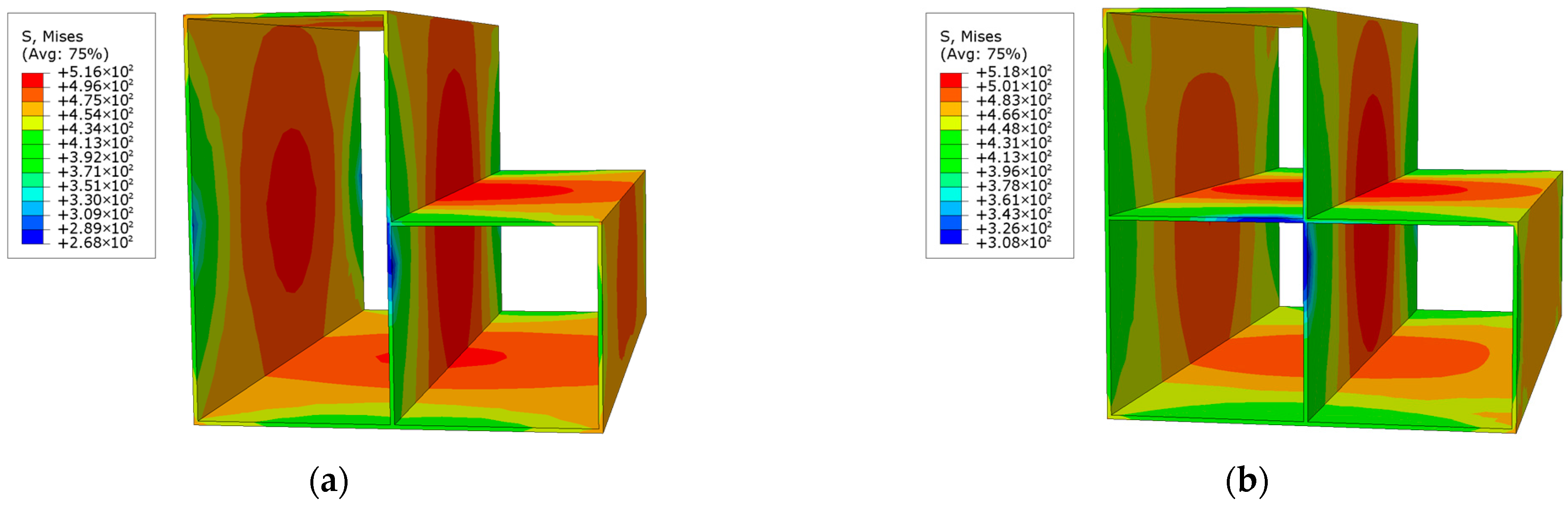
Further insights can be derived from the stress contour plots of the support plates at maximum displacement, shown in
Figure 22. These plots indicate that the yield stress area of the perforated support plate is significantly larger than that of the unperforated plate. In the perforated support plate, high-stress regions are primarily concentrated around the circular holes, with the maximum stress reaching critical levels in these areas. In contrast, the unperforated support plate exhibits a maximum stress value of approximately 480 MPa, but this stress is distributed over a relatively smaller area. The concentrated stress distribution around the perforations suggests that the perforated support plates effectively contribute to energy dissipation under loading conditions.
Overall, the findings indicate that perforating the support plates is a practical and effective modification to L-shaped CFST columns. The perforations allow for interconnected chambers within the steel tube, thereby simplifying construction processes and reducing the on-site workload. At the same time, the structural integrity and performance of the columns are preserved, with potential enhancements in the post-peak compressive strength and energy dissipation capabilities. The larger yield stress area and concentrated stress regions around the perforations suggest improved structural resilience, making perforated support plates a favorable design feature. Consequently, it is recommended that perforations be incorporated into support plates in practical construction applications to enhance both the construction efficiency and the structural performance of L-shaped CFST columns.
5.5. Height of CFST Column
Taking the CFST-M-2 specimen as the baseline model, the column height was adjusted to 800 mm to establish the CFST-H-1 model. The finite element analysis results, including the ultimate bearing capacity and the load–displacement relationship, are presented in
Figure 23. The ultimate bearing capacity of the CFST-H-1 model is 4030.6 kN, which is 1.1% lower than that of the CFST-M-2 model, which has a column height of 600 mm. This indicates that reducing the column height has a marginally positive effect in terms of enhancing the ultimate bearing capacity, although the influence is relatively small.
As illustrated in
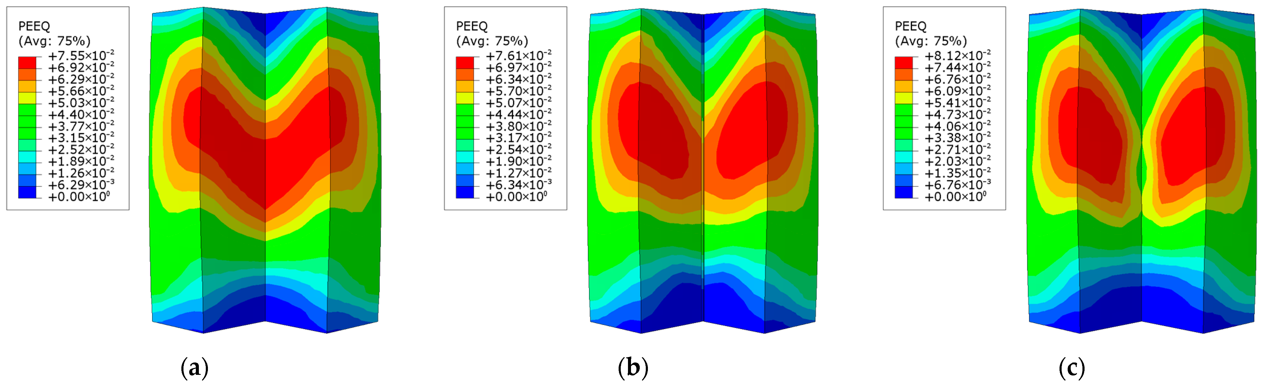
Figure 24, the distribution of the equivalent plastic strain reveals that both the 600 mm and 800 mm column heights lead to relatively high equivalent plastic strain in the midsection of the concave corner of the L-shaped concrete column. For the 600 mm column, the region with high strain is more concentrated, indicating localized deformation. In contrast, for the 800 mm column, the high-strain region extends beyond the concave corner, affecting a larger area that includes the short-side surface of the concrete. This increase in the affected area suggests that a taller column leads to a more distributed and extensive strain development within the concrete. As the column height increases, the potential for concrete cracking also rises due to the greater strain accumulation. Therefore, in practical engineering design and construction, it is crucial to carefully control the column height to manage strain distribution and minimize the risk of cracking.
5.6. Partial Damage Analysis of Concrete
Figure 25 illustrates the compressive damage distribution in the concrete portion of the L-shaped CFST columns at the final failure stage, based on the finite element analysis. As shown, apart from the CFST-H-1 specimen with a column height of 800 mm, the overall compressive damage distribution in the specimens is relatively consistent: less damage is observed at both ends of the columns, severe damage occurs near the central core region, and the concave corner areas at the ends exhibit the least damage. This indicates that altering the steel strength or steel tube thickness or adding internal stiffener plates has a limited influence on the overall failure pattern of the concrete core.
A comparison of
Figure 25b,i reveals that the compressive damage in the concrete is primarily concentrated in the mid-height region of the columns, and, as the column height increases, the extent of the most severely damaged zone decreases. Specifically, when the L-shaped CFST column reaches its ultimate failure stage, if the column height is relatively small, a large portion of the in-tube concrete undergoes compressive failure, potentially causing the crushing of the concrete surface. Conversely, if the column height is relatively large, the zone of compressive failure within the concrete core becomes smaller and is confined to the middle segment, which can lead to cracking in this region.
6. Conclusions
This study focused on the axial compressive performance of L-shaped CFST columns and examined the effects of installing support plates. The key research parameters included the steel strength, the pipe thickness, the number of support plates, and the presence of holes in the support plates. Nine finite element models were developed for parametric analysis, and the findings reveal the following.
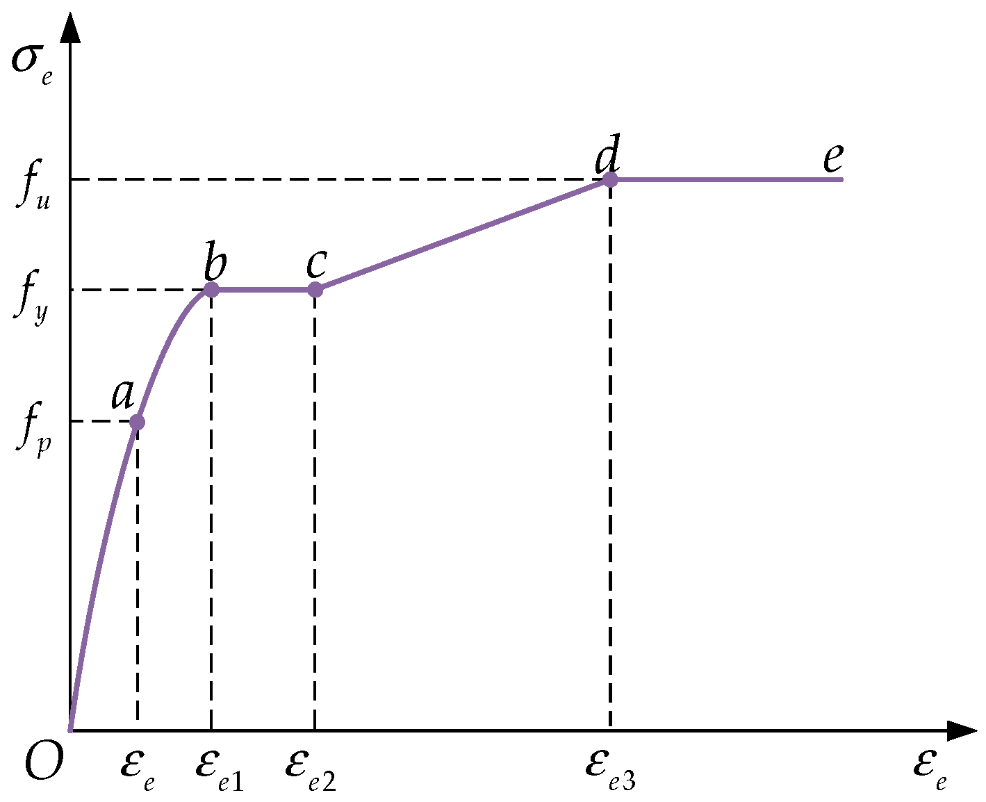
The axial compression behavior of the L-shaped CFST column can be divided into three distinct phases: the elastic phase, the elastoplastic phase, and the failure phase. At the conclusion of the elastic phase, the steel pipe, except for the regions at the top and bottom ends, reaches its yield stress, resulting in a relatively uniform stress distribution within the steel pipe.
The ultimate bearing capacity of L-shaped CFST columns under eccentric loading is approximately 82% of that observed under axial compression. Eccentric loading induces a shift in the bulging position at the corner of the L-shaped steel tube, moving it upward. The installation of support plates enhances the ultimate bearing capacity of L-shaped CFST columns under eccentric loading. In the model without support plates (CFST-M-2) and the model with two support plates (CFST-S-2), V-shaped cracks develop at the upper part of the concave corner of the concrete column. However, in the model with perforated support plates (CFST-S-3), the equivalent plastic strain around the corner is effectively reduced, which helps to suppress crack propagation in the corner region.
As the steel strength grade increases, the initial stiffness and deformation capacity of the L-shaped CFST column remain largely unchanged. However, when the steel strength is upgraded from Q235B to Q345B and Q420B, the model’s ultimate bearing capacity increases by 8.5% and 12.6%, respectively. The enhancement in steel strength effectively improves the load-bearing capacity factor of the L-shaped CFST column, leading to the greater confinement of the concrete by the steel, thereby improving the overall load-bearing performance.
Compared with the CFST-T-1 model, which had a steel pipe thickness of 2 mm, the ultimate bearing capacity of the column models with steel pipe thicknesses of 3 mm and 4 mm increased by 12.5% and 25.1%, respectively. After entering the plastic failure stage, the load–displacement curves for the CFST-T-1, CFST-M-2, and CFST-T-3 models dropped to 58.1%, 65.2%, and 68.8% of their respective ultimate loads before stabilizing. Increasing the steel pipe thickness enhances the compressive capacity of the L-shaped CFST column after it reaches the ultimate bearing capacity.
The installation of support plates can effectively enhance the ultimate bearing capacity of the L-shaped CFST column. As the number of support plates increases, the rate of load decreases in the descending section of the load–displacement curve slows down, which can effectively reduce the load drop and improve the compressive capacity of the L-shaped CFST column after reaching its ultimate bearing capacity.
Perforating the support plates of the L-shaped CFST column, which connects the previously separated chambers, enhances the efficiency of concrete pouring. The simulation results indicate that the presence of holes has a minimal impact on both the ultimate bearing capacity and the compressive strength of the column after reaching its ultimate load. Under eccentric loading, the reduced stiffness of the perforated support plates allows them to bear a greater load. In areas where specific compressive bearing capacity requirements are not critical, perforating the support plates is recommended to improve the construction efficiency.
Reducing the column height of L-shaped CFST columns can improve their ultimate bearing capacity, although the effect is relatively modest. Conversely, increasing the column height raises the risk of cracking in the midsection of the concave corner. Therefore, in practical engineering applications, it is crucial to carefully control the column height to minimize the risk of concrete cracking and ensure structural integrity.
Our future work will focus on conducting numerical studies to investigate the effects of the hole type, hole quantity, and plate thickness in the internal support plates of the steel tube on the axial compressive performance of short columns. In addition, experimental analyses will be conducted to further explore the load-bearing capacity of L-shaped CFST columns, the buckling behavior of the steel tube, and the compressive failure mechanisms of the in-tube concrete. Moreover, the seismic performance of beam–column joints suitable for this type of CFST column will also be examined.


