
Chemical Compatibility of Li1.3Al0.3Ti1.7(PO4)3 Solid-State Electrolyte Co-Sintered with Li4Ti5O12 Anode for Multilayer Ceramic Lithium Batteries

 , , , ,
Highlights
- The first systematic study focused on the chemical compatibility of Li1.3Al0.3Ti1.7(PO4)3 (LATP) solid-state electrolyte co-sintered with Li4Ti5O12 (LTO) anode materials, and the feasibility for application in multilayer ceramic lithium batteries (MLCBs) was demonstrated.
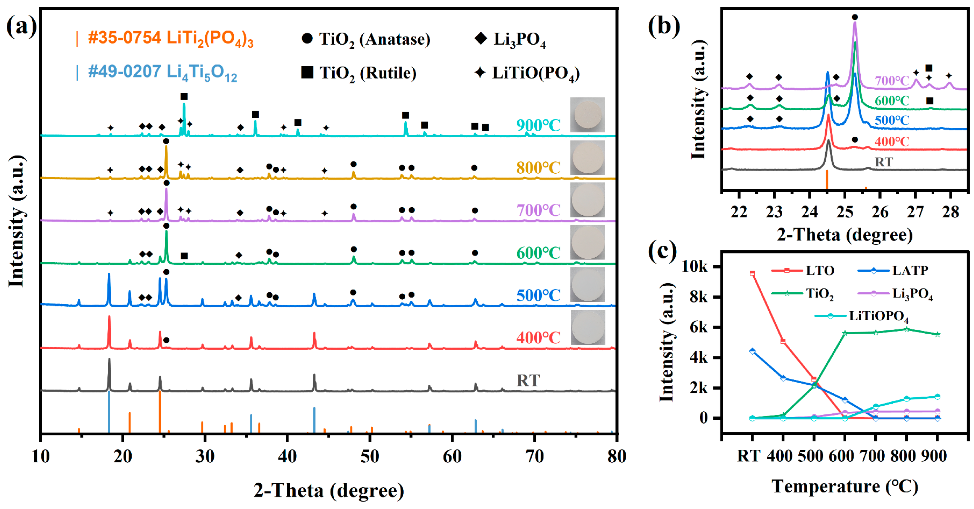
- It was found that Li diffusion at high temperatures induced the reactions between LATP and LTO, resulting in the formation of secondary phases including TiO2, Li3PO4, and LiTiOPO4.
- The co-sintered LATP-LTO multilayer composites revealed that the formation of Li3PO4 effectively promoted the co-sintering integration of LATP and LTO at 800–900 °C, which is essential for the successful fabrication of MLCBs.
Abstract
1. Introduction
2. Materials and Methods
2.1. Preparation of LATP-LTO Composite Electrode Pellets
2.2. Preparation of LATP-LTO Multilayer Composite Sheets
2.3. Sample Characterization
3. Results and Discussion
- (1)
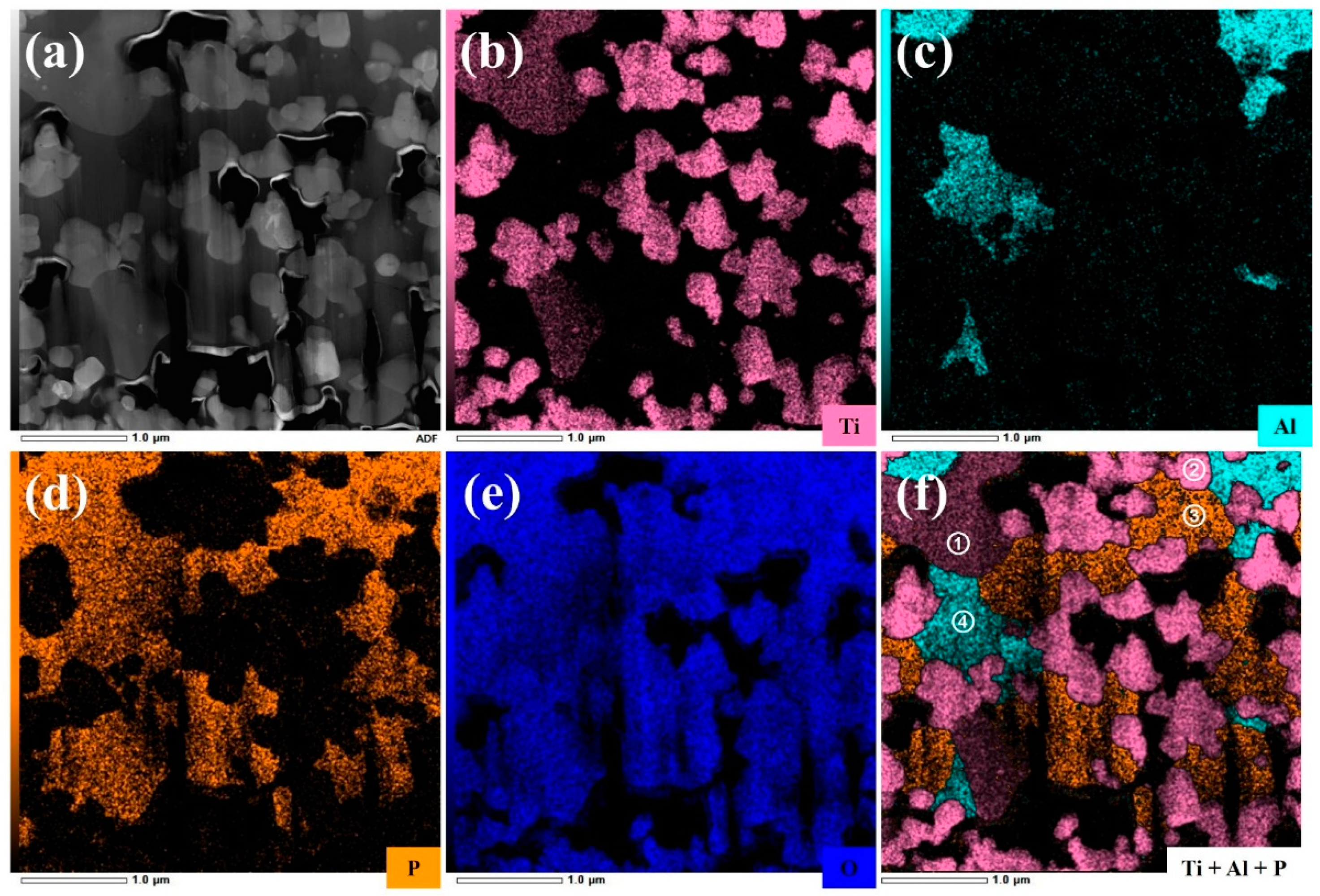
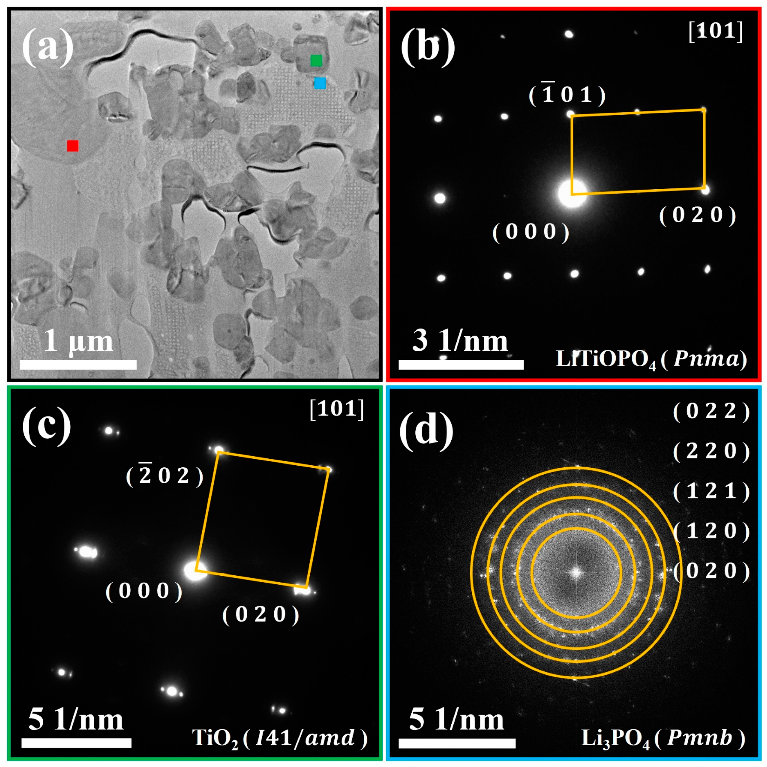
- Region ①: this region predominantly consists of Ti, P, and O elements. Combined with the SAED pattern shown in Figure 6b, it can be confirmed as the LiTiOPO4 phase;
- (2)
- Region ②: this region predominantly consists of Ti and O elements. The SAED results in Figure 6c confirm that it corresponds to anatase TiO2;
- (3)
- Region ③: this region predominantly consists of P and O elements. As shown in Figure 6d and Figure S4b,d it comprises polycrystalline Li3PO4 and an amorphous phase;
- (4)
- Region ④: this region predominantly contains Al, P, and O elements, likely corresponding to the formation of AlPO4. Figure S4b,c reveal that this region is amorphous, which explains the absence of Al-containing secondary phases in the XRD analysis.
4. Conclusions
Supplementary Materials
Author Contributions
Funding
Institutional Review Board Statement
Informed Consent Statement
Data Availability Statement
Acknowledgments
Conflicts of Interest
References
- Pikul, J.H.; Ning, H. Powering the Internet of Things. Joule 2018, 2, 1036–1038. [Google Scholar] [CrossRef]
- Zhu, Z.; Kan, R.; Hu, S.; He, L.; Hong, X.; Tang, H.; Luo, W. Recent Advances in High-Performance Microbatteries: Construction, Application, and Perspective. Small 2020, 16, 2003251. [Google Scholar] [CrossRef] [PubMed]
- Yue, X.; Johnson, A.C.; Kim, S.; Kohlmeyer, R.R.; Patra, A.; Grzyb, J.; Padmanabha, A.; Wang, M.; Jiang, Z.; Sun, P.; et al. A Nearly Packaging-Free Design Paradigm for Light, Powerful, and Energy-Dense Primary Microbatteries. Adv. Mater. 2021, 33, 2101760. [Google Scholar] [CrossRef] [PubMed]
- Kim, S.; Patra, A.; Kohlmeyer, R.R.; Jo, S.; Yue, X.; Johnson, A.; Kiggins, C.T.; Zahiri, B.; Jeong, K.; Koo, J.; et al. Serially Integrated High-Voltage and High Power Miniature Batteries. Cell Rep. Phys. Sci. 2023, 4, 101205. [Google Scholar] [CrossRef]
- Liu, L.; Weng, Q.; Lu, X.; Sun, X.; Zhang, L.; Schmidt, O.G. Advances on Microsized On-Chip Lithium-Ion Batteries. Small 2017, 13, 1701847. [Google Scholar] [CrossRef]
- Liu, H.; Zhang, G.; Zheng, X.; Chen, F.; Duan, H. Emerging Miniaturized Energy Storage Devices for Microsystem Applications: From Design to Integration. Int. J. Extrem. Manuf. 2020, 2, 042001. [Google Scholar] [CrossRef]
- Kyeremateng, N.A.; Hahn, R. Attainable Energy Density of Microbatteries. ACS Energy Lett. 2018, 3, 1172–1175. [Google Scholar] [CrossRef]
- Wu, Y.; Liu, X.; Wang, L.; Feng, X.; Ren, D.; Li, Y.; Rui, X.; Wang, Y.; Han, X.; Xu, G.-L.; et al. Development of Cathode-Electrolyte-Interphase for Safer Lithium Batteries. Energy Storage Mater. 2021, 37, 77–86. [Google Scholar] [CrossRef]
- Wang, Q.; Lu, T.; Xiao, Y.; Wu, J.; Guan, L.; Hou, L.; Du, H.; Wei, H.; Liu, X.; Yang, C.; et al. Leap of Li Metal Anodes from Coin Cells to Pouch Cells: Challenges and Progress. Electrochem. Energy Rev. 2023, 6, 22. [Google Scholar] [CrossRef]
- Li, J.; Ma, C.; Chi, M.; Liang, C.; Dudney, N.J. Solid Electrolyte: The Key for High-Voltage Lithium Batteries. Adv. Energy Mater. 2015, 5, 1401408. [Google Scholar] [CrossRef]
- Lin, J.; Lin, L.; Qu, S.; Deng, D.; Wu, Y.; Yan, X.; Xie, Q.; Wang, L.; Peng, D.-L. Promising Electrode and Electrolyte Materials for High-Energy-Density Thin-Film Lithium Batteries. Energy Environ. Mater. 2022, 5, 133–156. [Google Scholar] [CrossRef]
- Wu, T.; Dai, W.; Ke, M.; Huang, Q.; Lu, L. All-Solid-State Thin Film μ-Batteries for Microelectronics. Adv. Sci. 2021, 8, 2100774. [Google Scholar] [CrossRef]
- Komuro, T.; Fujita, T. Multilayer Ceramic Li-Ion Secondary Battery. In Proceedings of the 2018 International Conference on Electronics Packaging and iMAPS All Asia Conference (ICEP-IAAC), Mie, Japan, 17–21 April 2018; pp. 230–233. [Google Scholar]
- Xia, Q.; Zan, F.; Zhang, Q.; Liu, W.; Li, Q.; He, Y.; Hua, J.; Liu, J.; Xu, J.; Wang, J.; et al. All-Solid-State Thin Film Lithium/Lithium-Ion Microbatteries for Powering the Internet of Things. Adv. Mater. 2023, 35, 2200538. [Google Scholar] [CrossRef] [PubMed]
- Zubairi, H.; Lu, Z.; Zhu, Y.; Reaney, I.M.; Wang, G. Current Development, Optimisation Strategies and Future Perspectives for Lead-Free Dielectric Ceramics in High Field and High Energy Density Capacitors. Chem. Soc. Rev. 2024, 53, 10761–10790. [Google Scholar] [CrossRef] [PubMed]
- Lou, S.; Zhang, F.; Fu, C.; Chen, M.; Ma, Y.; Yin, G.; Wang, J. Interface Issues and Challenges in All-Solid-State Batteries: Lithium, Sodium, and Beyond. Adv. Mater. 2021, 33, 2000721. [Google Scholar] [CrossRef]
- Kim, K.J.; Rupp, J.L.M. All Ceramic Cathode Composite Design and Manufacturing towards Low Interfacial Resistance for Garnet-Based Solid-State Lithium Batteries. Energy Environ. Sci. 2020, 13, 4930–4945. [Google Scholar] [CrossRef]
- Han, X.; Wang, S.; Xu, Y.; Zhong, G.; Zhou, Y.; Liu, B.; Jiang, X.; Wang, X.; Li, Y.; Zhang, Z.; et al. All Solid Thick Oxide Cathodes Based on Low Temperature Sintering for High Energy Solid Batteries. Energy Environ. Sci. 2021, 14, 5044–5056. [Google Scholar] [CrossRef]
- Miara, L.; Windmu, A.; Uhlenbruck, S.; Guillon, O.; Ceder, G. About the Compatibility between High Voltage Spinel Cathode Materials and Solid Oxide Electrolytes as a Function of Temperature. ACS Appl. Mater. Interfaces 2016, 8, 26842–26850. [Google Scholar] [CrossRef] [PubMed]
- Ren, Y. Chemical Compatibility between Garnet-like Solid State Electrolyte Li6.75La3Zr1.75Ta0.25O12 and Major Commercial Lithium Battery Cathode Materials. J. Mater. 2016, 2, 256–264. [Google Scholar] [CrossRef]
- Gellert, M.; Dashjav, E.; Grüner, D.; Ma, Q.; Tietz, F. Compatibility Study of Oxide and Olivine Cathode Materials with Lithium Aluminum Titanium Phosphate. Ionics 2018, 24, 1001–1006. [Google Scholar] [CrossRef]
- Yu, C.-Y.; Choi, J.; Anandan, V.; Kim, J.-H. High-Temperature Chemical Stability of Li1.4Al0.4Ti1.6(PO4)3 Solid Electrolyte with Various Cathode Materials for Solid-State Batteries. J. Phys. Chem. C 2020, 124, 14963–14971. [Google Scholar] [CrossRef]
- Zhu, Y.; Gonzalez-Rosillo, J.C.; Balaish, M.; Hood, Z.D.; Kim, K.J.; Rupp, J.L.M. Lithium-Film Ceramics for Solid-State Lithionic Devices. Nat. Rev. Mater. 2021, 6, 313–331. [Google Scholar] [CrossRef]
- Yin, J.-H.; Zhu, H.; Yu, S.-J.; Dong, Y.-B.; Wei, Q.-Y.; Xu, G.-Q.; Xiong, Y.; Qian, Y. Recent Advances of LATP and Their NASICON Structure as a Solid-State Electrolyte for Lithium-Ion Batteries. Adv. Eng. Mater. 2023, 25, 2300566. [Google Scholar] [CrossRef]
- Wu, P.; Zhou, W.; Su, X.; Li, J.; Su, M.; Zhou, X.; Sheldon, B.W.; Lu, W. Recent Advances in Conduction Mechanisms, Synthesis Methods, and Improvement Strategies for Li1+xAlxTi2-x(PO4)3 Solid Electrolyte for All-Solid-State Lithium Batteries. Adv. Energy Mater. 2023, 13, 2203440. [Google Scholar] [CrossRef]
- Han, C.; He, Y.-B.; Liu, M.; Li, B.; Yang, Q.-H.; Wong, C.-P.; Kang, F. A Review of Gassing Behavior in Li4Ti5O12-Based Lithium Ion Batteries. J. Mater. Chem. A 2017, 5, 6368–6381. [Google Scholar] [CrossRef]
- Chen, Z.; Li, H.; Wu, L.; Lu, X.; Zhang, X. Li4Ti5O12 Anode: Structural Design from Material to Electrode and the Construction of Energy Storage Devices. Chem. Rec. 2018, 18, 350–380. [Google Scholar] [CrossRef]
- Banerjee, A.; Wang, X.; Fang, C.; Wu, E.A.; Meng, Y.S. Interfaces and Interphases in All-Solid-State Batteries with Inorganic Solid Electrolytes. Chem. Rev. 2020, 120, 6878–6933. [Google Scholar] [CrossRef]
- Chen, L.; Huang, Y.-F.; Ma, J.; Ling, H.; Kang, F.; He, Y.-B. Progress and Perspective of All-Solid-State Lithium Batteries with High Performance at Room Temperature. Energy Fuels 2020, 34, 13456–13472. [Google Scholar] [CrossRef]
- Miao, X.; Guan, S.; Ma, C.; Li, L.; Nan, C.-W. Role of Interfaces in Solid-State Batteries. Adv. Mater. 2023, 35, 2206402. [Google Scholar] [CrossRef] [PubMed]
- Yi, T.-F.; Xie, Y.; Zhu, Y.-R.; Zhu, R.-S.; Shen, H. Structural and Thermodynamic Stability of Li4Ti5O12 Anode Material for Lithium-Ion Battery. J. Power Sources 2013, 222, 448–454. [Google Scholar] [CrossRef]
- Gao, Y.; Wang, Z.; Chen, L. Stability of Spinel Li4Ti5O12 in Air. J. Power Sources 2014, 245, 684–690. [Google Scholar] [CrossRef]
- Rumpel, M.; Appold, L.; Baber, J.; Stracke, W.; Flegler, A.; Sextl, G. Impact of the Sintering Additive Li3PO4 on the Sintering Behaviour, Microstructure and Electrical Properties of a Ceramic LATP Electrolyte. Mater. Adv. 2022, 3, 8157–8167. [Google Scholar] [CrossRef]
- Xu, Q.; Zhang, J.; Feng, Z.; Ma, Y.; Wang, X.; Li, C. Surface Structural Transformation and the Phase Transition Kinetics of Brookite TiO2. Chem.-Asian J. 2010, 5, 2158–2161. [Google Scholar] [CrossRef] [PubMed]
- Li, G.; Li, L.; Boerio-Goates, J.; Woodfield, B.F. High Purity Anatase TiO2 Nanocrystals: Near Room-Temperature Synthesis, Grain Growth Kinetics, and Surface Hydration Chemistry. J. Am. Chem. Soc. 2005, 127, 8659–8666. [Google Scholar] [CrossRef] [PubMed]
- Lu, Y.; Yang, F.; Wang, G.G.X.; Shi, S.; Liu, Y. Enhanced Electrochemical Properties and Thermal Stability of Zr4+ Doped Li1.20Mn0.54Ni0.13Co0.13O2 Cathode Material by a Li Ion Conductor of Li3PO4 Surface Coating. Appl. Surf. Sci. 2020, 521, 146338. [Google Scholar] [CrossRef]
- Liu, J.; Wei, A.X.; Chen, M.; Xia, X. Rational Synthesis of Li4Ti5O12/N-C Nanotube Arrays as Advanced High-Rate Electrodes for Lithium-Ion Batteries. J. Mater. Chem. A 2018, 6, 3857–3863. [Google Scholar] [CrossRef]
- Appapillai, A.T.; Mansour, A.N.; Cho, J.; Shao-Horn, Y. Microstructure of LiCoO2 with and without “AlPO4” Nanoparticle Coating: Combined STEM and XPS Studies. Chem. Mater. 2007, 19, 5748–5757. [Google Scholar] [CrossRef]
- Wang, Q.; Liu, L.; Zhao, B.; Zhang, L.; Xiao, X.; Yan, H.; Xu, G.; Ma, L.; Liu, Y. Transport and Interface Characteristics of Te-Doped NASICON Solid Electrolyte Li1.3Al0.3Ti1.7(PO4)3. Electrochim. Acta 2021, 399, 139367. [Google Scholar] [CrossRef]
- Yamada, H.; Morimoto, N.; Mukohara, H.; Tojo, T.; Yano, S.; Magome, E.; Morimura, T.; Bekarevich, R.; Mitsuishi, K. Concerted Influence of Microstructure and Adsorbed Water on Lithium-Ion Conduction of Li1.3Al0.3Ti1.7(PO4)3. J. Power Sources 2021, 511, 230422. [Google Scholar] [CrossRef]
- Ali, B.; Muhammad, R.; Moeez, I.; Park, J.-H.; Islam, M.; Cho, M.-K.; Kim, J.-Y.; Chung, K.Y.; Nam, K.-W. Improving High-Rate and Long-Life Cycling of Li4Ti5O12 Anode by Dual Doping of Cd2+ and Ge4+. Adv. Sustain. Syst. 2024, 8, 2400337. [Google Scholar] [CrossRef]
- Kusiak-Nejman, E.; Wróbel, R.J.; Kapica-Kozar, J.; Wanag, A.; Szymańska, K.; Mijowska, E.; Morawski, A.W. Hybrid Carbon-TiO2 Spheres: Investigation of Structure, Morphology and Spectroscopic Studies. Appl. Surf. Sci. 2019, 469, 684–690. [Google Scholar] [CrossRef]
- Wu, Y.; Ben, L.; Yu, H.; Qi, W.; Zhan, Y.; Zhao, W.; Huang, X. Understanding the Effect of Atomic-Scale Surface Migration of Bridging Ions in Binding Li3PO4 to the Surface of Spinel Cathode Materials. ACS Appl. Mater. Interfaces 2019, 11, 6937–6947. [Google Scholar] [CrossRef] [PubMed]
- Wang, L.; Wang, L.; Shi, Q.; Zhong, C.; Gong, D.; Wang, X.; Zhan, C.; Liu, G. In-situ constructed SnO2 gradient buffer layer as a tight and robust interphase toward Li metal anodes in LATP solid state batteries. J. Energy Chem. 2023, 80, 89–98. [Google Scholar] [CrossRef]
- Beaupain, J.P.; Waetzig, K.; Otto, S.-K.; Henss, A.; Janek, J.; Malaki, M.; Pokle, A.; Müller, J.; Butz, B.; Volz, K.; et al. Reaction of Li1.3Al0.3Ti1.7(PO4)3 and LiNi0.6Co0.2Mn0.2O2 in Co-Sintered Composite Cathodes for Solid-State Batteries. ACS Appl. Mater. Interfaces 2021, 13, 47488–47498. [Google Scholar] [CrossRef] [PubMed]
- Malaki, M.; Pokle, A.; Otto, S.-K.; Henss, A.; Beaupain, J.P.; Beyer, A.; Müller, J.; Butz, B.; Wätzig, K.; Kusnezoff, M.; et al. Advanced Analytical Characterization of Interface Degradation in Ni-Rich NCM Cathode Co-Sintered with LATP Solid Electrolyte. ACS Appl. Energy Mater. 2022, 5, 4651–4663. [Google Scholar] [CrossRef]
- Xu, Q.; Tsai, C.L.; Song, D.; Basak, S.; Kungl, H.; Tempel, H.; Hausen, F.; Yu, S.; Eichel, R.A. Insights into the Reactive Sintering and Separated Specific Grain/Grain Boundary Conductivities of Li1.3Al0.3Ti1.7(PO4)3. J. Power Sources 2021, 492, 229631. [Google Scholar] [CrossRef]
- Gao, Y.; Cheng, C.; An, J.; Liu, H.; Zhang, D.; Chen, G.; Shi, L. High Tap Density Li4Ti5O12 Anode Materials Synthesized for High Rate Performance Lithium Ion Batteries. ChemistrySelect 2018, 3, 348–353. [Google Scholar] [CrossRef]
- Ayu, N.I.P.; Kartini, E.; Prayogi, L.D.; Faisal, M. Supardi Crystal Structure Analysis of Li3PO4 Powder Prepared by Wet Chemical Reaction and Solid-State Reaction by Using X-Ray Diffraction (XRD). Ionics 2016, 22, 1051–1057. [Google Scholar] [CrossRef]
- Kawano, Y.; Kato, A.; Usui, H.; Domi, Y.; Sakaguchi, H. TiO2 Anode Material for All-Solid-State Battery Using NASICON Li1.5Al0.5Ge1.5(PO4)3 as Lithium Ion Conductor. Electrochemistry 2023, 91, 067003. [Google Scholar] [CrossRef]


Disclaimer/Publisher’s Note: The statements, opinions and data contained in all publications are solely those of the individual author(s) and contributor(s) and not of MDPI and/or the editor(s). MDPI and/or the editor(s) disclaim responsibility for any injury to people or property resulting from any ideas, methods, instructions or products referred to in the content. |
© 2025 by the authors. Licensee MDPI, Basel, Switzerland. This article is an open access article distributed under the terms and conditions of the Creative Commons Attribution (CC BY) license (https://creativecommons.org/licenses/by/4.0/).
Share and Cite
Li, J.; Ma, M.; Mao, Y.; Zhang, F.; Feng, J.; Lyu, Y.; Lan, T.; Li, Y.; Liu, Z. Chemical Compatibility of Li1.3Al0.3Ti1.7(PO4)3 Solid-State Electrolyte Co-Sintered with Li4Ti5O12 Anode for Multilayer Ceramic Lithium Batteries. Materials 2025, 18, 851. https://doi.org/10.3390/ma18040851
Li J, Ma M, Mao Y, Zhang F, Feng J, Lyu Y, Lan T, Li Y, Liu Z. Chemical Compatibility of Li1.3Al0.3Ti1.7(PO4)3 Solid-State Electrolyte Co-Sintered with Li4Ti5O12 Anode for Multilayer Ceramic Lithium Batteries. Materials. 2025; 18(4):851. https://doi.org/10.3390/ma18040851
Chicago/Turabian StyleLi, Jiangtao, Mingsheng Ma, Ya Mao, Faqiang Zhang, Jingjing Feng, Yingchun Lyu, Tu Lan, Yongxiang Li, and Zhifu Liu. 2025. "Chemical Compatibility of Li1.3Al0.3Ti1.7(PO4)3 Solid-State Electrolyte Co-Sintered with Li4Ti5O12 Anode for Multilayer Ceramic Lithium Batteries" Materials 18, no. 4: 851. https://doi.org/10.3390/ma18040851
APA StyleLi, J., Ma, M., Mao, Y., Zhang, F., Feng, J., Lyu, Y., Lan, T., Li, Y., & Liu, Z. (2025). Chemical Compatibility of Li1.3Al0.3Ti1.7(PO4)3 Solid-State Electrolyte Co-Sintered with Li4Ti5O12 Anode for Multilayer Ceramic Lithium Batteries. Materials, 18(4), 851. https://doi.org/10.3390/ma18040851