
Springback Analysis and Prediction of Automotive Steel Sheets Used in Compression Bending


Abstract
1. Introduction
2. Materials and Methods
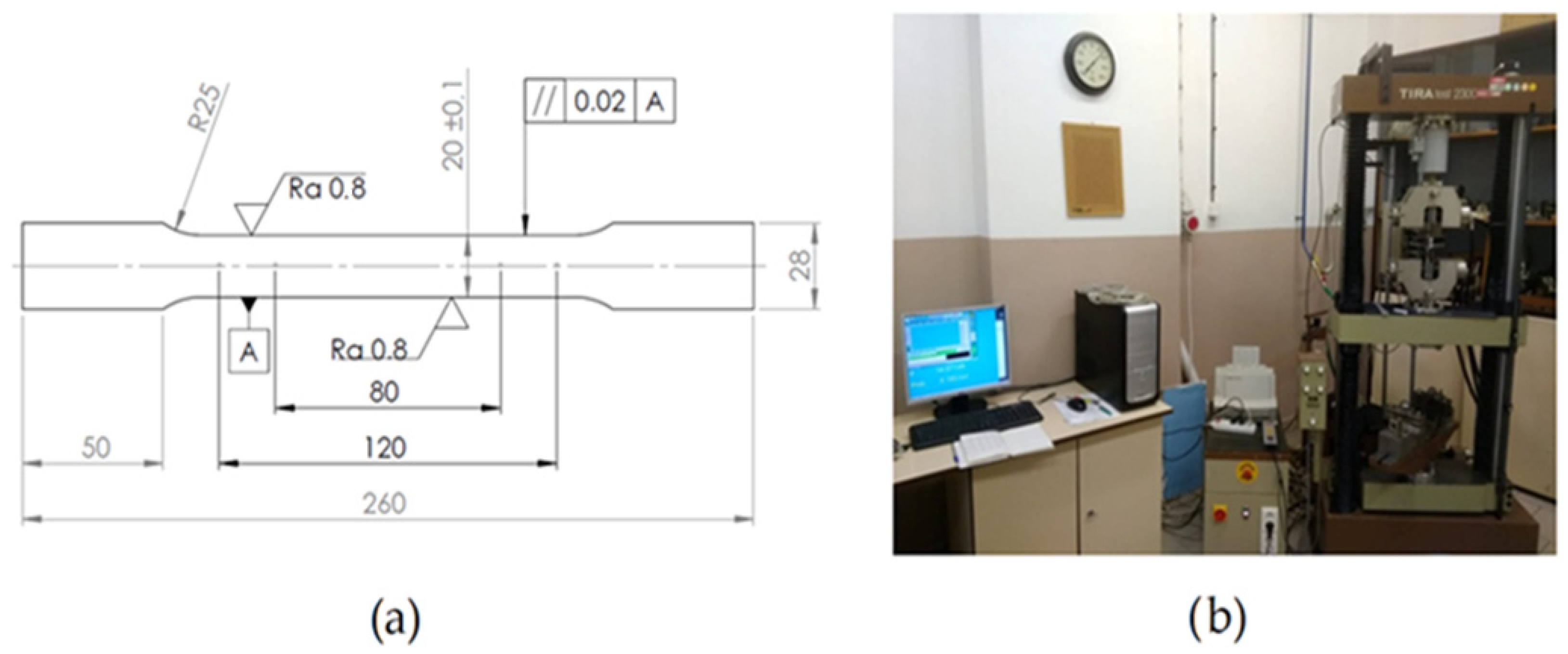
2.1. Materials
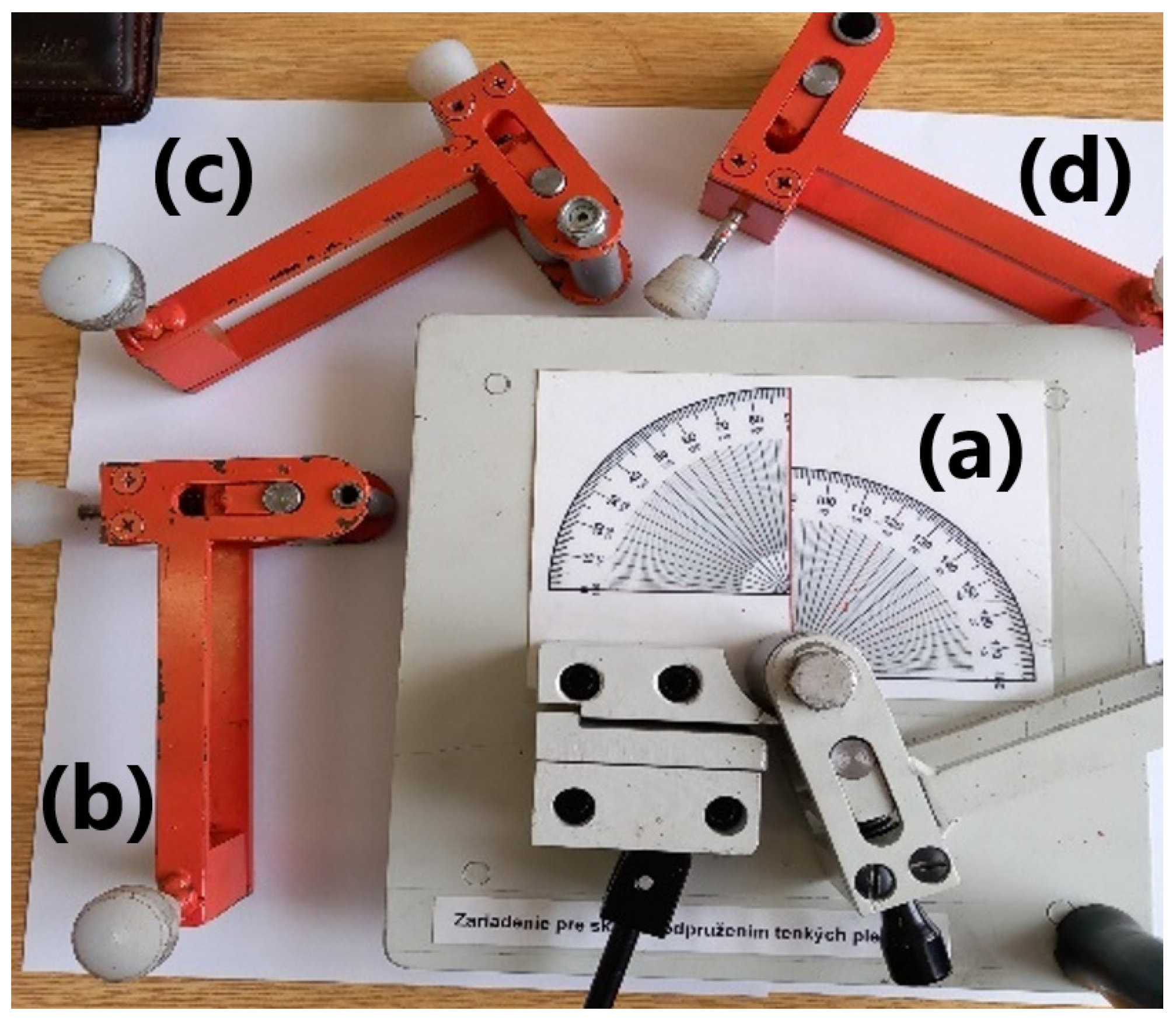
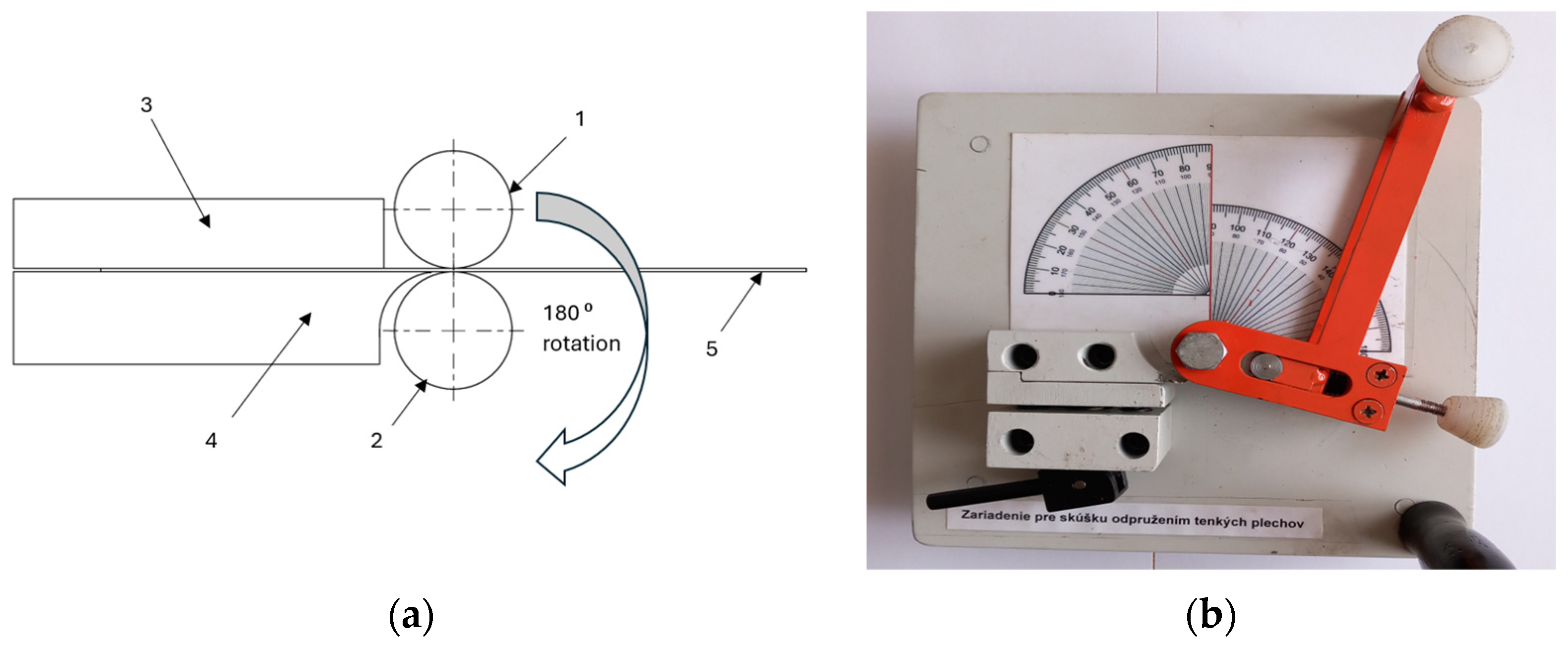
2.2. Experimental Setup
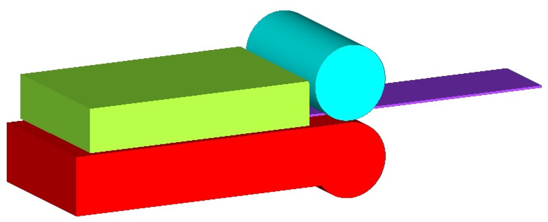
2.3. Simulation Setup
Yield Criteria and Hardening Model
3. Results
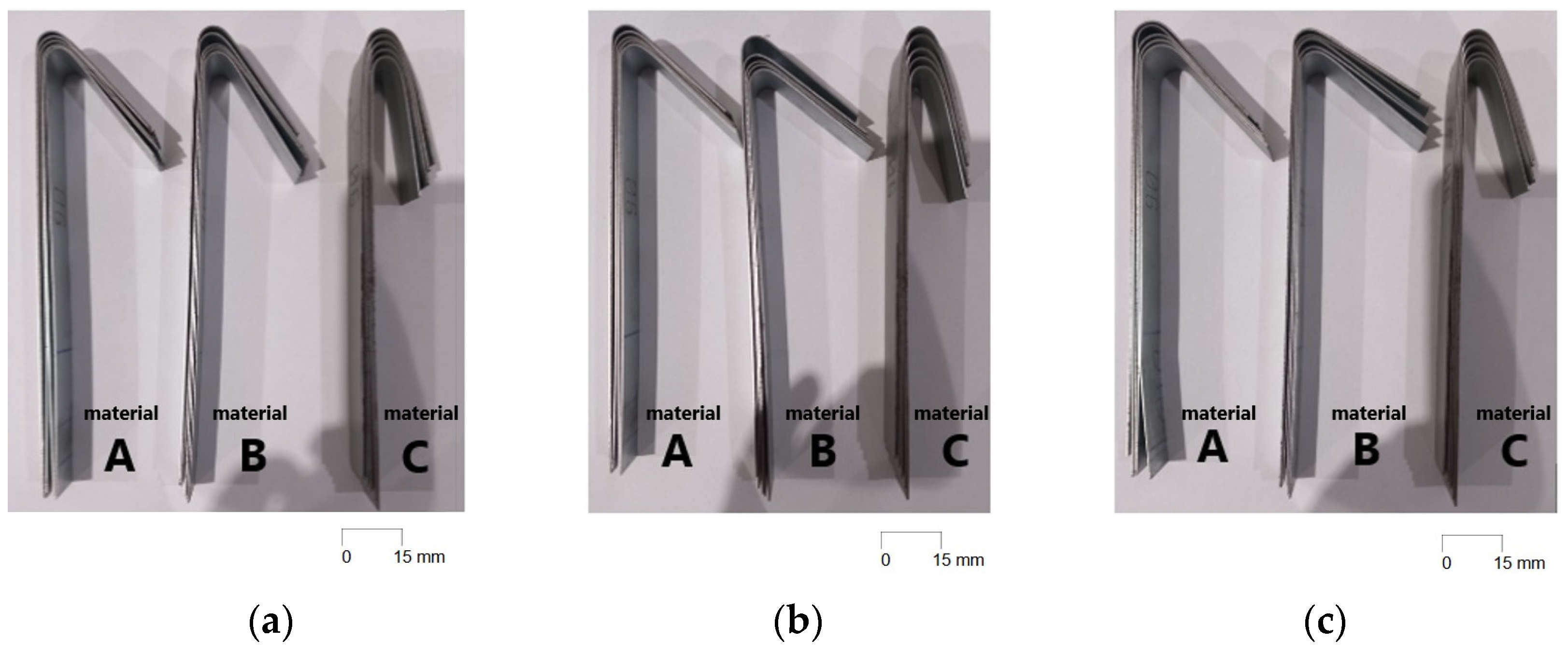
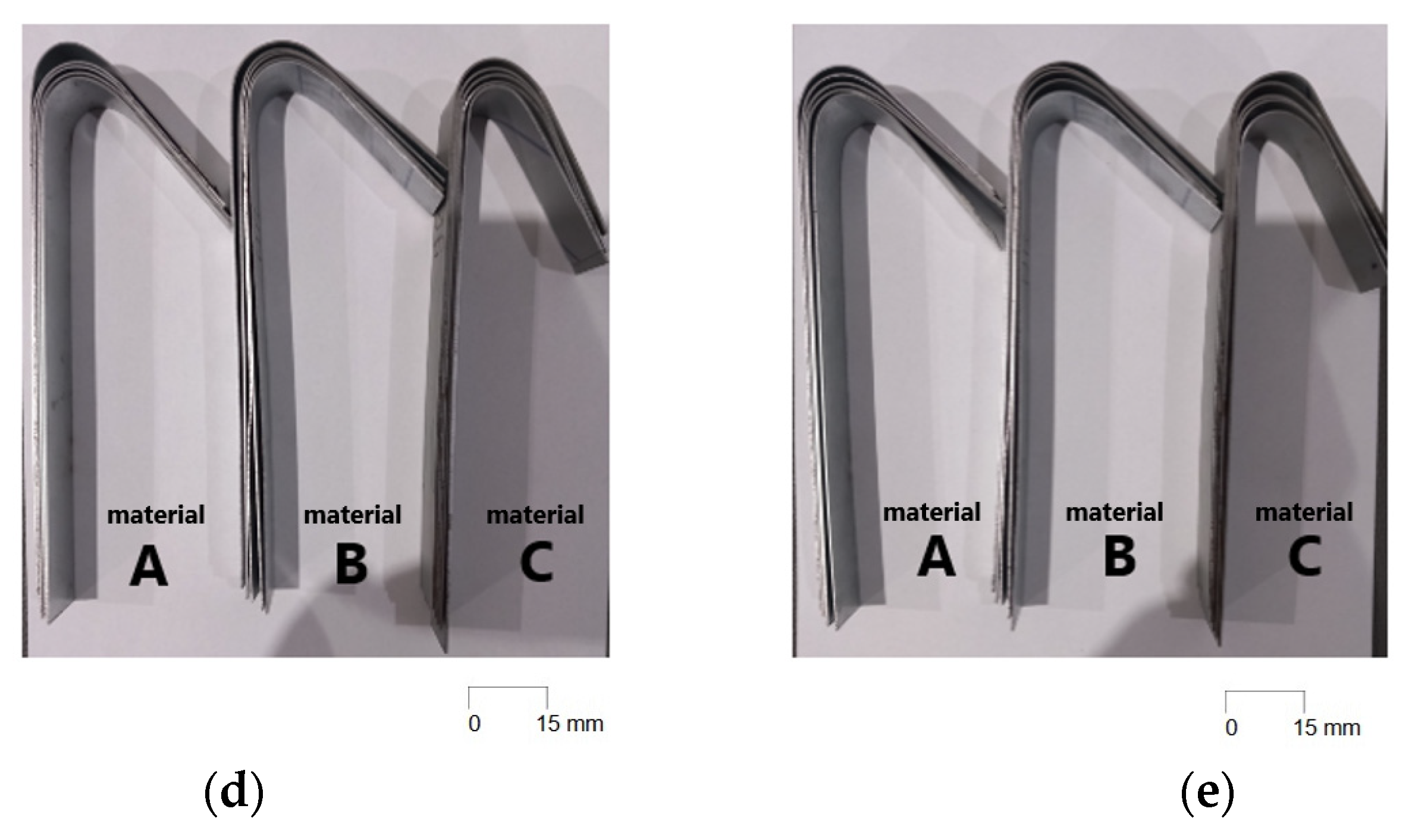
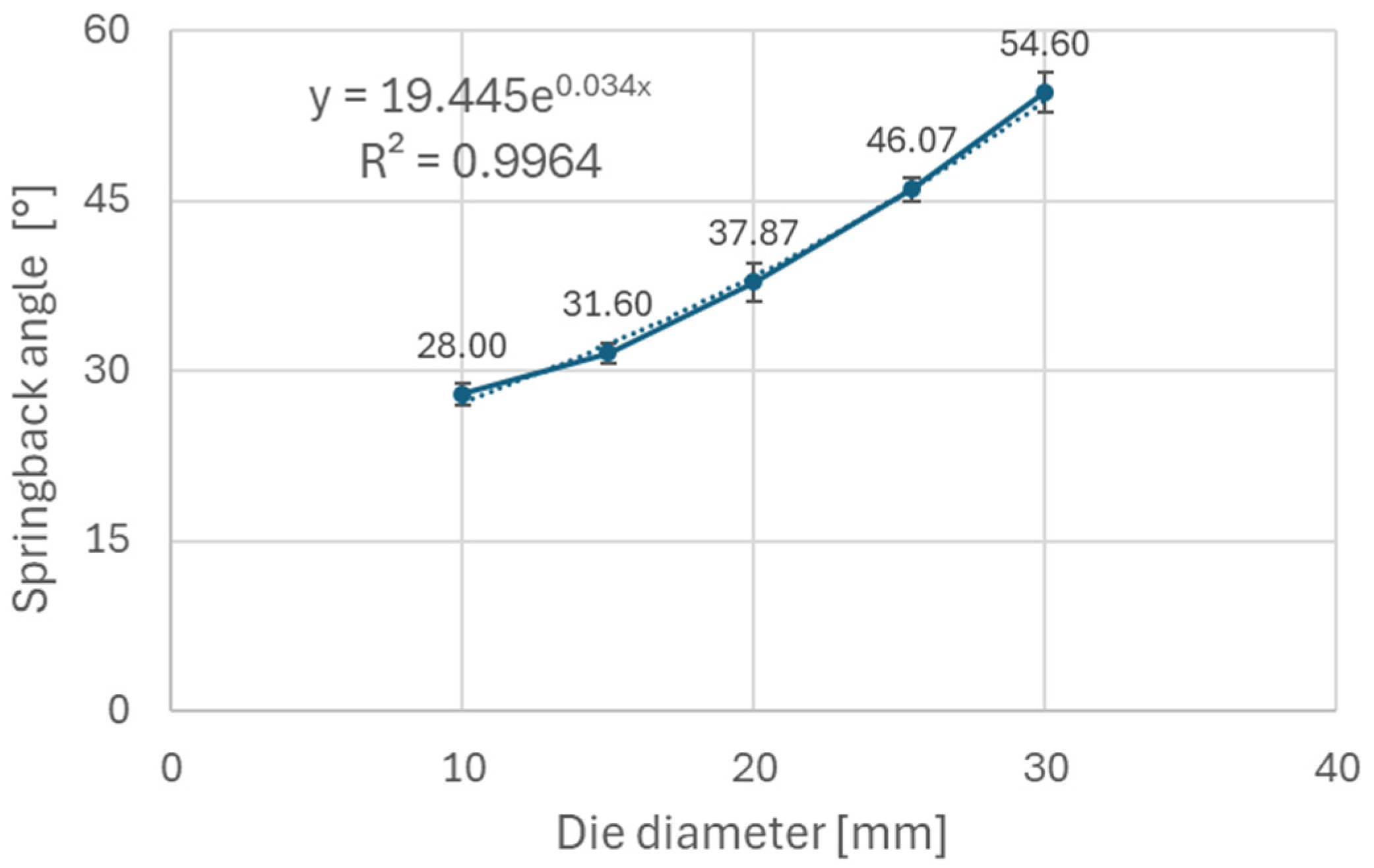
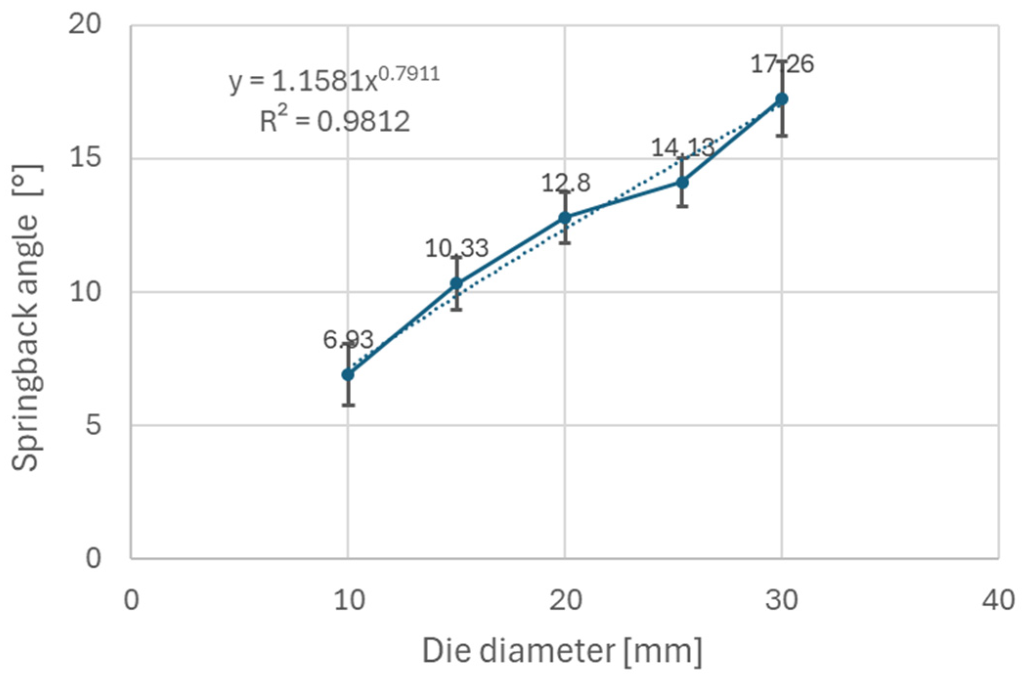
3.1. Analysis of Springback Results from Experiment
3.2. Analysis of Springback Results from Simulation
4. Discussion
5. Conclusions
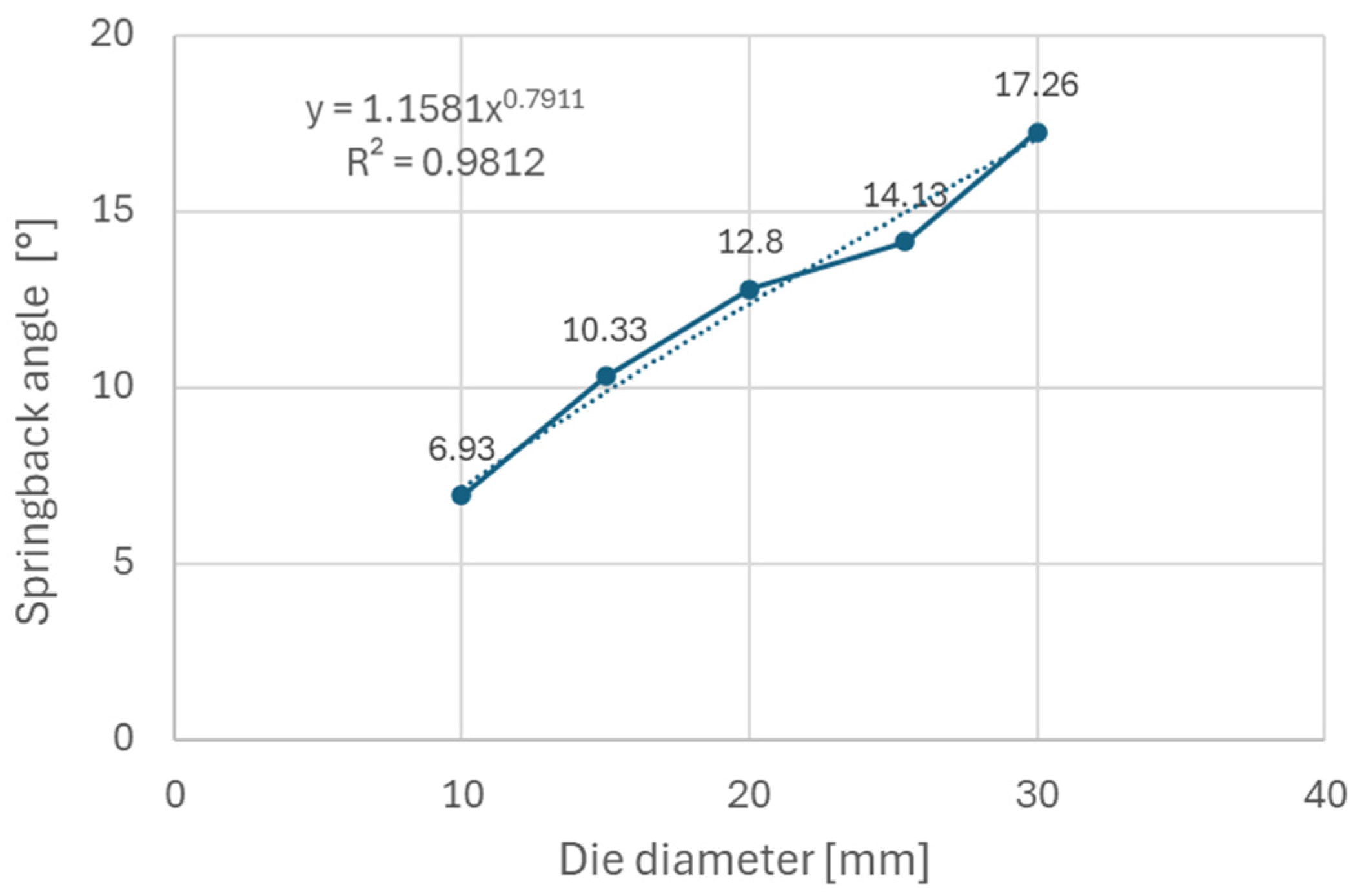
- Die diameter has a significant impact on the springback of the tested steels, and use of smaller die diameters decreases the impact of elastic deformation on total deformation, thus reducing springback. Parts made in a tool with 10 mm die diameter had approximately 50% less springback than parts made in a tool with 30 mm die diameter.
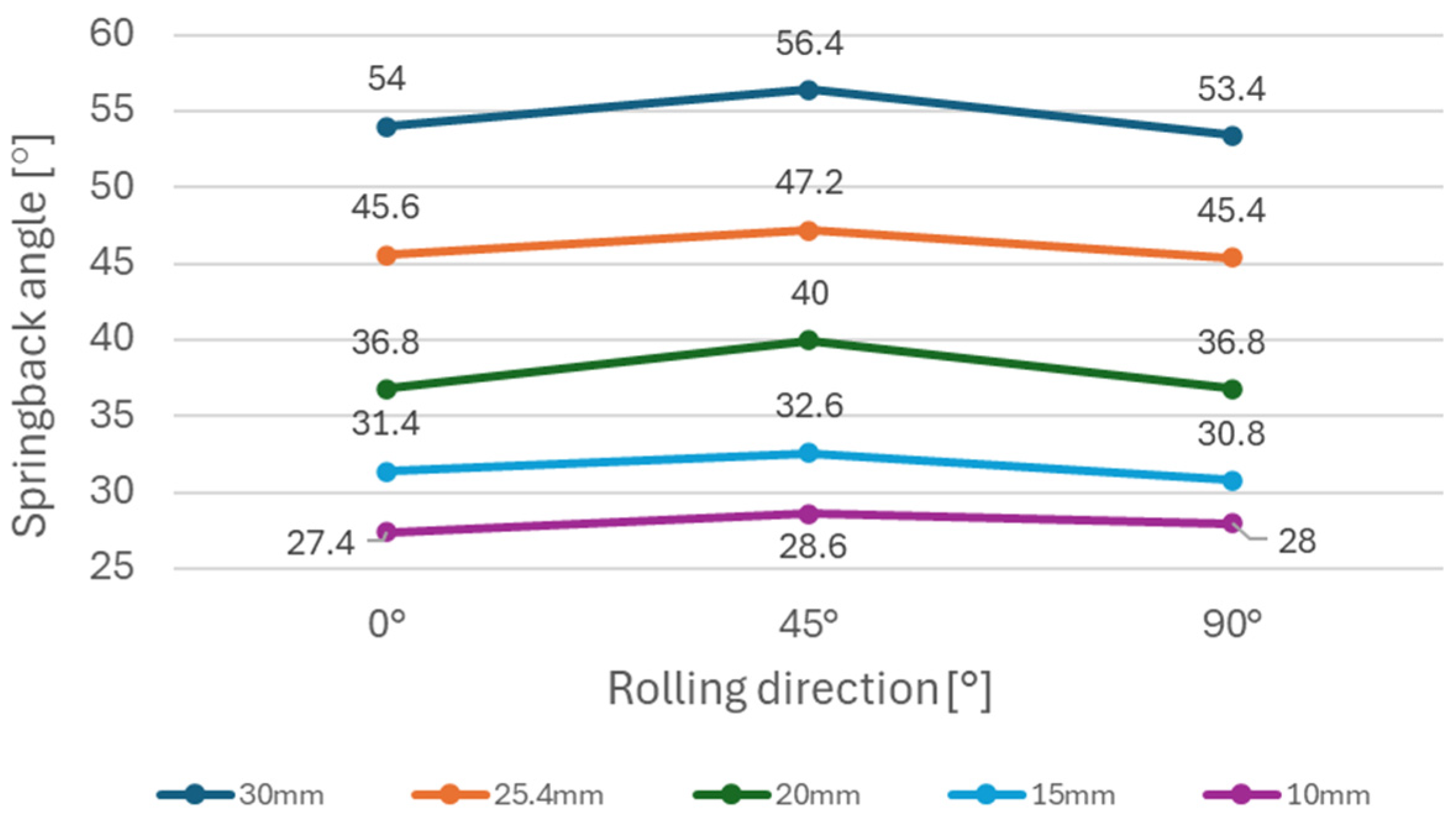
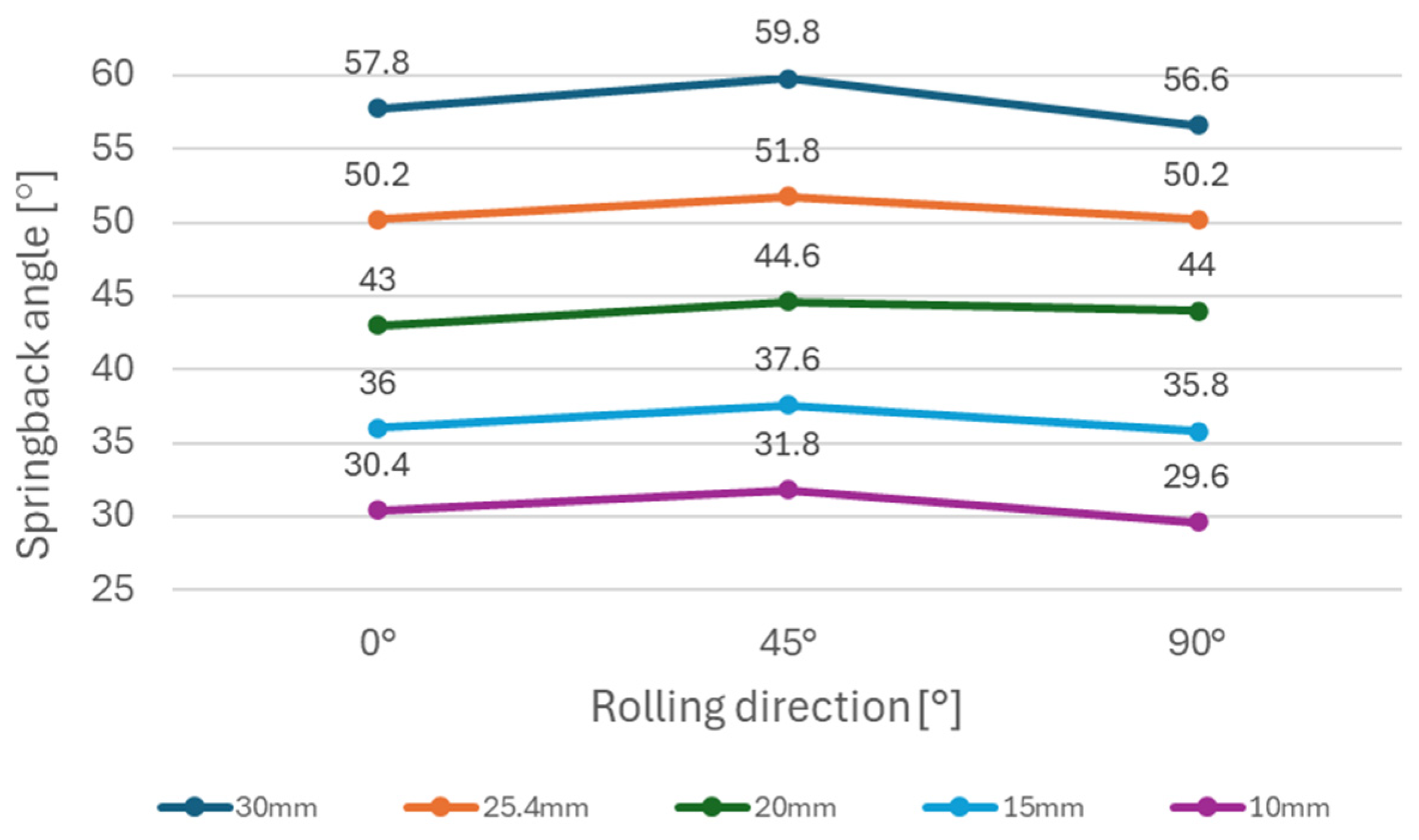
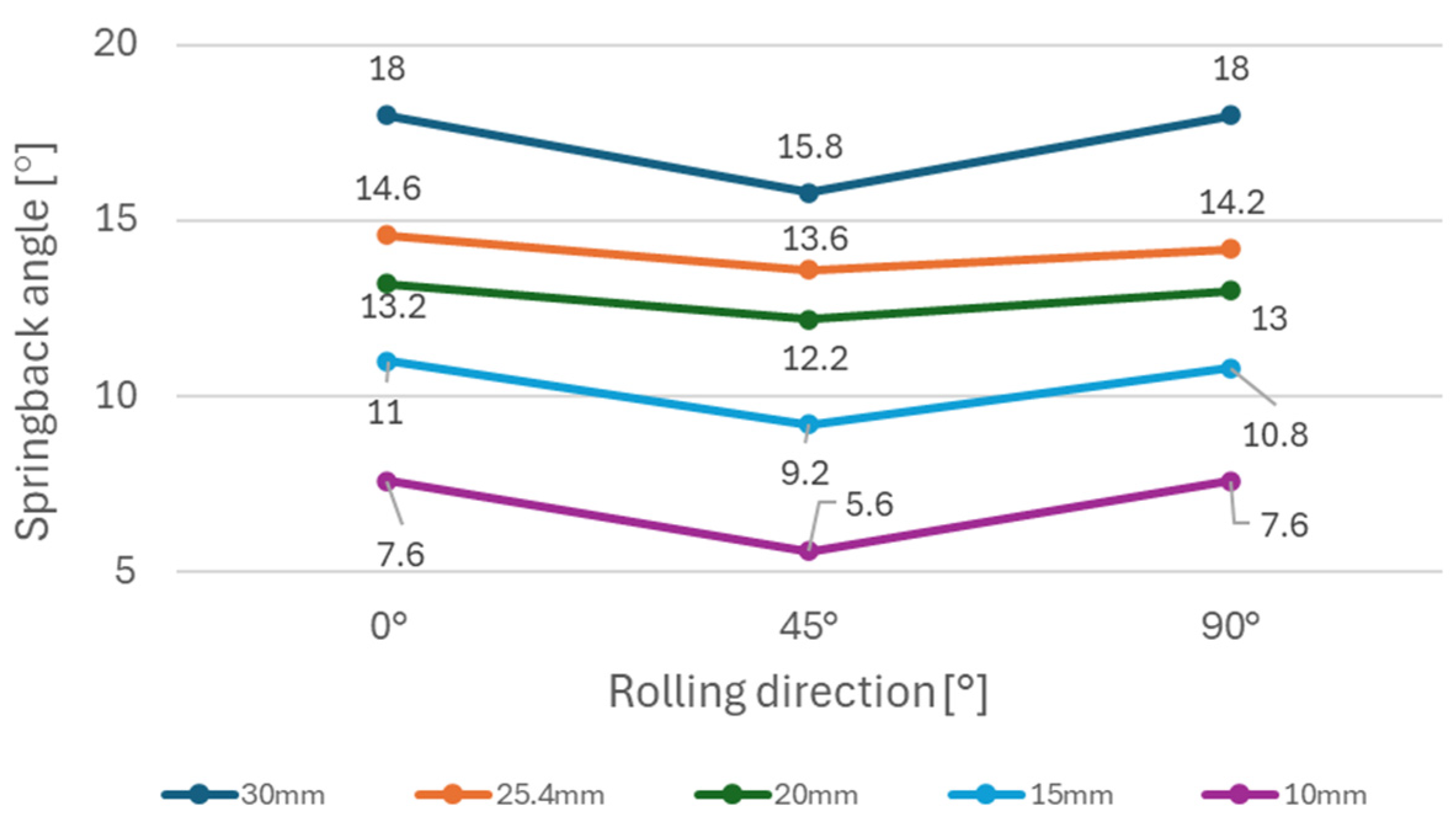
- The impact of material anisotropy on springback was less prominent compared to the impact of die diameter. Anisotropy had the greatest effect on the springback angle when DC06 steel was used in the experiment. Samples of DC06 steel prepared in the 45° direction had up to 13% less springback after bending compared to samples prepared in the 0° and 90° directions.
- The Hollomon hardening rule in combination with Hill48 and Barlat91 yield criteria demonstrated inaccurate springback predictions when the high strength steels RAK 40/70 and HX420 were tested in a simulation of the compression bending process. Accuracy of springback predictions was more satisfactory when DC06 steel was used in the simulation.
- Springback predictions were closer to experimental values when a smaller size of elements was employed in simulations.
Author Contributions
Funding
Institutional Review Board Statement
Informed Consent Statement
Data Availability Statement
Conflicts of Interest
References
- Trzepieciński, T. Forming processes of modern metallic materials. Metals 2020, 10, 970. [Google Scholar] [CrossRef]
- Chongthairungruang, B.; Uthaisangsuk, V.; Suranuntchai, S.; Jirathearanat, S. Springback prediction in sheet metal forming of high strength steels. Mater. Des. 2013, 50, 253–266. [Google Scholar] [CrossRef]
- Jeswiet, J.; Geiger, M.; Engel, U.; Kleiner, M.; Schikorra, M.; Duflou, J.; Neugebauer, R.; Bariani, P.; Bruschi, S. Metal forming progress since 2000. CIRP J. Manuf. Sci. Technol. 2008, 1, 2–17. [Google Scholar] [CrossRef]
- Masato, U. Joining technologies for automotive steel sheets. Weld. Int. 2011, 25, 249–259. [Google Scholar] [CrossRef]
- Choi, D.Y.; Young, G.K. Trend of Joining Technology for Automotive Sheet Steels. J. Korean Weld. Join. Soc. 2009, 27, 7–12. [Google Scholar] [CrossRef]
- Mulidrán; Spišák, E.; Tomáš, M.; Majerníková, J.; Rohaľ, V. Numerical simulation of bending steels used in automotive industry with emphasis on springback. Acta Metall. Slovaca 2024, 30, 41–46. [Google Scholar] [CrossRef]
- Wagoner, R.H.; Lim, H.; Lee, M.-G. Advanced Issues in springback. Int. J. Plast. 2013, 45, 3–20. [Google Scholar] [CrossRef]
- Džupon, M.; Kaščák, Ľ.; Cmorej, D.; Čiripová, L.; Mucha, J.; Spišák, E. Clinching of High-Strength Steel Sheets with Local Preheating. Appl. Sci. 2023, 13, 7790. [Google Scholar] [CrossRef]
- Baluch, N.; Udin, Z.; Abdullah, C.S. Advanced High Strength Steel in Auto Industry: An Overview. Eng. Technol. Appl. Sci. Res. 2014, 4, 686–689. [Google Scholar] [CrossRef]
- Kvačkaj, T.; Bidulská, J.; Bidulský, R. Overview of HSS Steel Grades Development and Study of Reheating Condition Effects on Austenite Grain Size Changes. Materials 2021, 14, 1988. [Google Scholar] [CrossRef]
- Xu, G.; Gan, X.; Ma, G.; Luo, F.; Zou, H. The development of Ti-alloyed high strength microalloy steel. Mater. Des. 2010, 31, 2891–2896. [Google Scholar] [CrossRef]
- Karmakar, A.; Biswas, S.; Mukherjee, S.; Chakrabarti, D.; Kumar, V. Effect of composition and thermo-mechanical processing schedule on the microstructure, precipitation and strengthening of Nb-microalloyed steels. Mater. Sci. Eng. A 2017, 690, 158–169. [Google Scholar] [CrossRef]
- Villalobos, J.C.; Del-Pozo, A.; Campillo, B.; Mayen, J.; Serna, S. Microalloyed Steels through History until 2018: Review of Chemical Composition, Processing and Hydrogen Service. Metals 2018, 8, 351. [Google Scholar] [CrossRef]
- Victor, A.; Victor, P. TRIP Steels: Factors influencing their formation, Mechanical Properties and Microstructure—A Review. J. Mech. Civ. Eng. 2022, 19, 37–60. [Google Scholar]
- Alexopoulos, N.D. Low-alloy TRIP Steels: Evaluation of the Mechanical Performance with regard to Material Design Requirements in the Automotive Industry. Steel Res. Int. 2006, 77, 129–138. [Google Scholar] [CrossRef]
- Xu, B.; Chen, P.; Li, Z.; Wu, D.; Wang, G.; Guo, J.; Liu, R.; Misra, R.D.K.; Yi, H. The Significance of Optimizing Mn-Content in Tuning the Microstructure and Mechanical Properties of δ-TRIP Steels. Metals 2021, 11, 523. [Google Scholar] [CrossRef]
- Perka, A.K.; John, M.; Kuruveri, U.B.; Menezes, P.L. Advanced High-Strength Steels for Automotive Applications: Arc and Laser Welding Process, Properties, and Challenges. Metals 2022, 12, 1051. [Google Scholar] [CrossRef]
- Konzack, S.; Radonjic, R.; Liewald, M.; Altan, T. Prediction and reduction of springback in 3D hat shape forming of AHSS. Procedia Manuf. 2018, 15, 660–667. [Google Scholar] [CrossRef]
- Karaağaç, I. The Evaluation of Process Parameters on Springback in V-bending Using the Flexforming Process. Mater. Res. 2017, 20, 1291–1299. [Google Scholar] [CrossRef]
- Mulidrán, P.; Spišák, E.; Tomáš, M.; Slota, J.; Majerníková, J. Numerical Prediction and Reduction of Hat-Shaped Part Springback Made of Dual-Phase AHSS Steel. Metals 2020, 10, 1119. [Google Scholar] [CrossRef]
- Tomáš, M.; Evin, E.; Kepič, J.; Hudák, J. Physical Modelling and Numerical Simulation of the Deep Drawing Process of a Box-Shaped Product Focused on Material Limits Determination. Metals 2019, 9, 1058. [Google Scholar] [CrossRef]
- Solfronk, P.; Sobotka, J.; Koreček, D. Effect of the Computational Model and Mesh Strategy on the Springback Prediction of the Sandwich Material. Machines 2022, 10, 114. [Google Scholar] [CrossRef]
- Di Pietro, O.; Napoli, G.; Gaggiotti, M.; Marini, R.; Di Schino, A. Analysis of Forming Parameters Involved in Plastic De-formation of 441 Ferritic Stainless Steel Tubes. Metals 2020, 10, 1013. [Google Scholar] [CrossRef]
- Slota, J.; Jurčišin, M. Experimental and Numerical Prediction of Springback in V-Bending of Anisotropic sheet metals for automotive industry. Zeszyty Naukowe Politechniki Rzeszowskiej. Mechanika 2012, 84, 55–68. [Google Scholar]
- Wasif, M.; Fatima, A.; Ahmed, A.; Iqbal, S.A. Investigation and Optimization of Parameters for the Reduced Springback in JSC-590 Sheet Metals Occurred During the V-Bending Process. Trans. Indian Inst. Met. 2021, 74, 2751–2760. [Google Scholar] [CrossRef]
- Uemori, T.; Sumikawa, S.; Naka, T.; Ma, N.; Yoshida, F. Influence of Bauschinger Effect and Anisotropy on Springback of Aluminum Alloy Sheets. Mater. Trans. 2017, 58, 921–926. [Google Scholar] [CrossRef]
- Mulidrán, P.; Spišák, E.; Tomáš, M.; Majerníková, J.; Bidulská, J.; Bidulský, R. Impact of Blank Holding Force and Friction on Springback and Its Prediction of a Hat-Shaped Part Made of Dual-Phase Steel. Materials 2023, 16, 811. [Google Scholar] [CrossRef]
- Ikumapayi, O.M.; Akinlabi, E.T.; Madushele, N.; Fatoba, S.O. A Brief Overview of Bending Operation in Sheet Metal Forming. In Advances in Manufacturing Engineering; Emamian, S.S., Awang, M., Yusof, F., Eds.; Lecture Notes in Mechanical Engineering; Springer: Singapore, 2020. [Google Scholar] [CrossRef]
- Saleh, M.H.; Priestner, R. Retained austenite in dual-phase silicon steels and its effect on mechanical properties. J. Mater. Process. Technol. 2001, 113, 587–593. [Google Scholar] [CrossRef]
- Di Schino, A. Analysis of phase transformation in high strength low alloyed steels. Metalurgija 2017, 56, 349–352. [Google Scholar]
- Mancini, S.; Langellotto, L.; Di Nunzio, P.E.; Zitelli, C.; Di Schino, A. Defect reduction and quality optimisation by modelling plastic deformation and metallurgical evolution in ferritic stainless steels. Metals 2020, 10, 186. [Google Scholar] [CrossRef]
- Toros, S.; Polat, A.; Ozturk, F. Formability and springback characterization of TRIP800 advanced high strength steel. Mater. Des. 2012, 41, 298–305. [Google Scholar] [CrossRef]
- ISO 10113:2020; Metallic Materials—Sheet and Strip—Determination of Plastic Strain Ratio. International Organization for Standardization: Geneva, Switzerland, 2020.
- ISO 10275:2020; Metallic Materials—Sheet and Strip—Determination of Tensile Strain Hardening Exponent. International Organization for Standardization: Geneva, Switzerland, 2020.
- ISO 6892-1:2019; Metallic Materials—Tensile Testing—Part 1: Method of Test at Room Temperature. International Organization for Standardization: Geneva, Switzerland, 2019.
- Tinplate Hardness Tester—BLTE1000. Available online: https://www.sabatec.ch/pdf/flyers/BLTE1000_flyer_2021-10-14_web_en.pdf (accessed on 22 November 2024).
- Evin, E. Evaluation of Friction Coefficient of Stamping. Acta Mech. Slovaca 2014, 18, 20–27. [Google Scholar] [CrossRef]
- Trzepiecinski, T. A Study of the Coefficient of Friction in Steel Sheets Forming. Metals 2019, 9, 988. [Google Scholar] [CrossRef]
- Jirková, H.; Opatová, K.; Jeníček, Š.; Vrtáček, J.; Kučerová, L.; Kurka, P. Use of multi-phase trip steel for press-hardening technology. Acta Metall. Slovaca 2019, 25, 101–106. [Google Scholar] [CrossRef]
- Kjell, M.; Mats, S. An evaluation of some recent yield criteria for industrial simulations of sheet forming processes. Int. J. Mech. Sci. 2008, 50, 774–787. [Google Scholar]
- Abspoel, M.; Scholting, M.E.; Lansbergen, M.; An, Y.; Vegter, H. A new method for predicting advanced yield criteria input parameters from mechanical properties. J. Mater. Process. Technol. 2017, 248, 161–177. [Google Scholar] [CrossRef]
- Li, X.; Yang, Y.; Wang, Y.; Bao, J.; Li, S. Effect of the material-hardening mode on the springback simulation accuracy of V-free bending. J. Mater. Process. Technol. 2002, 123, 209–211. [Google Scholar] [CrossRef]
- Hill, R. A Theory of the Yielding and Plastic Flow of Anisotropic Metals. Proceedings of the Royal Society of London. Ser. A Math. Phys. Sci. 1947, 193, 281–297. [Google Scholar] [CrossRef]
- Barlat, F.; Lege, D.; Brem, J.C. A six-component yield function for anisotropic materials. Int. J. Plast. 1991, 7, 693–712. [Google Scholar] [CrossRef]
- Jurcisin, M.; Slota, J.; Dvorak, M. Numerical and experimental determination of springback in u-bending process. MM Sci. J. 2013, 12, 440–443. [Google Scholar] [CrossRef]
- Buang, S.; Shahrul, A.; Juri, A. Effect of Die and Punch Radius on Springback of Stainless Steel Sheet Metal in the Air V-Die Bending Process. J. Mech. Eng. Sci. 2015, 8, 1322–1331. [Google Scholar] [CrossRef]
- Wagoner, R.H.; Li, M. Simulation of springback: Through-thickness integration. Int. J. Plast. 2007, 23, 345–360. [Google Scholar] [CrossRef]
- Liu, J.G.; Fu, M.W.; Lu, J.; Chan, W.L. Influence of size effect on the springback of sheet metal foils in micro-bending. Comput. Mater. Sci. 2011, 50, 2604–2614. [Google Scholar] [CrossRef]
- Chatti, S.; Noureddine, H. The effect of non-linear recovery on springback prediction. Comput. Struct. 2011, 89, 1367–1377. [Google Scholar] [CrossRef]

| Material | C | Mn | Si | Cr | P | S | Al | Nb | Ti |
|---|---|---|---|---|---|---|---|---|---|
| A | 0.05 | 0.71 | 0.26 | 0.05 | <0.002 | <0.002 | 0.03 | 0.032 | <0.002 |
| B | 0.2 | 1.27 | 0.14 | 0.04 | 0.019 | <0.002 | 2.56 | 0.016 | 0.005 |
| C | 0.002 | 0.06 | 0.02 | 0.02 | <0.002 | <0.002 | 0.04 | 0.006 | 0.006 |
| Dir. [°] | Rp0.2 [MPa] | Rm [MPa] | A80 [%] | r [-] | rm [-] | n [-] | nm [-] |
|---|---|---|---|---|---|---|---|
| 0 | 468 | 522 | 22.2 | 0.790 | 0.143 | ||
| 45 | 465 | 512 | 24.0 | 1.096 | 0.895 | 0.142 | 0.144 |
| 90 | 454 | 522 | 18.8 | 0.599 | 0.151 |
| Dir. [°] | Rp0.2 [MPa] | Rm [MPa] | A80 [%] | r [-] | rm [-] | n [-] | nm [-] |
|---|---|---|---|---|---|---|---|
| 0 | 435 | 765 | 29.6 | 0.702 | 0.298 | ||
| 45 | 443 | 763 | 29.6 | 0.884 | 0.834 | 0.294 | 0.291 |
| 90 | 449 | 764 | 31.0 | 0.867 | 0.279 |
| Dir. [°] | Rp0.2 [MPa] | Rm [MPa] | A80 [%] | r [-] | rm [-] | n [-] | nm [-] |
|---|---|---|---|---|---|---|---|
| 0 | 157 | 301 | 46.9 | 2.224 | 0.267 | ||
| 45 | 159 | 302 | 46.0 | 1.552 | 1.812 | 0.256 | 0.261 |
| 90 | 148 | 298 | 49.8 | 1.921 | 0.265 |
| Material | K (MPa) | n (-) |
|---|---|---|
| HX420 | 791 | 0.144 |
| RAK 40/70 | 1488 | 0.291 |
| DC06 | 551 | 0.261 |
| Material | r0 (-) | r45 (-) | r90 (-) | σ0 (MPa) | σ45 (MPa) | σ90 (MPa) |
|---|---|---|---|---|---|---|
| HX420 | 0.790 | 1.096 | 0.599 | 468 | 465 | 454 |
| RAK 40/70 | 0.702 | 0.844 | 0.867 | 435 | 443 | 449 |
| DC06 | 2.224 | 1.552 | 1.921 | 157 | 159 | 148 |
| Yield Criterion | Element Size [mm] | Effective Plastic Strain [-] | Equivalent Stress [MPa] | Predicted Springback Angle [°] | Springback Angle from Experiment [°] | Deviation of Springback Prediction [°] |
|---|---|---|---|---|---|---|
| Hill48 | 0.34 | 0.12 | 282.44 | 9.85 | 45.60 | 35.75 |
| 0.17 | 0.15 | 313.99 | 13.64 | 31.96 | ||
| 0.085 | 0.17 | 324.88 | 14.11 | 31.49 | ||
| Barlat91 | 0.34 | 0.12 | 282.44 | 9.88 | 45.60 | 35.72 |
| 0.17 | 0.15 | 313.99 | 13.53 | 32.07 | ||
| 0.085 | 0.17 | 324.88 | 14.15 | 31.45 |
| Yield Criterion | Element Size [mm] | Effective Plastic Strain [-] | Equivalent Stress [MPa] | Predicted Springback Angle [°] | Springback Angle From Experiment [°] | Deviation of Springback Prediction [°] |
|---|---|---|---|---|---|---|
| Hill48 | 0.37 | 0.21 | 366.53 | 15.25 | 50.20 | 34.95 |
| 0.185 | 0.23 | 383.75 | 17.75 | 32.45 | ||
| 0.0925 | 0.23 | 388.3 | 17.90 | 32.30 | ||
| Barlat91 | 0.37 | 0.21 | 366.48 | 15.24 | 50.20 | 34.96 |
| 0.185 | 0.23 | 383.75 | 17.74 | 32.46 | ||
| 0.0925 | 0.23 | 388.31 | 18.56 | 31.64 |
| Yield Criterion | Element Size [mm] | Effective Plastic Strain [-] | Equivalent Stress [MPa] | Predicted Springback Angle [°] | Springback Angle from Experiment [°] | Deviation of Springback Prediction [°] |
|---|---|---|---|---|---|---|
| Hill48 | 0.42 | 0.05 | 103.15 | 11.27 | 14.60 | 3.33 |
| 0.21 | 0.06 | 132.26 | 11.56 | 3.04 | ||
| 0.105 | 0.08 | 153.29 | 11.90 | 2.70 | ||
| Barlat91 | 0.42 | 0.05 | 123.48 | 8.60 | 14.60 | 6.00 |
| 0.21 | 0.06 | 144.29 | 8.68 | 5.92 | ||
| 0.105 | 0.10 | 164.43 | 8.85 | 5.75 |
Disclaimer/Publisher’s Note: The statements, opinions and data contained in all publications are solely those of the individual author(s) and contributor(s) and not of MDPI and/or the editor(s). MDPI and/or the editor(s) disclaim responsibility for any injury to people or property resulting from any ideas, methods, instructions or products referred to in the content. |
© 2025 by the authors. Licensee MDPI, Basel, Switzerland. This article is an open access article distributed under the terms and conditions of the Creative Commons Attribution (CC BY) license (https://creativecommons.org/licenses/by/4.0/).
Share and Cite
Spišák, E.; Majerníková, J.; Mulidrán, P.; Hajduk, J.; Ruda, F. Springback Analysis and Prediction of Automotive Steel Sheets Used in Compression Bending. Materials 2025, 18, 774. https://doi.org/10.3390/ma18040774
Spišák E, Majerníková J, Mulidrán P, Hajduk J, Ruda F. Springback Analysis and Prediction of Automotive Steel Sheets Used in Compression Bending. Materials. 2025; 18(4):774. https://doi.org/10.3390/ma18040774
Chicago/Turabian StyleSpišák, Emil, Janka Majerníková, Peter Mulidrán, Július Hajduk, and František Ruda. 2025. "Springback Analysis and Prediction of Automotive Steel Sheets Used in Compression Bending" Materials 18, no. 4: 774. https://doi.org/10.3390/ma18040774
APA StyleSpišák, E., Majerníková, J., Mulidrán, P., Hajduk, J., & Ruda, F. (2025). Springback Analysis and Prediction of Automotive Steel Sheets Used in Compression Bending. Materials, 18(4), 774. https://doi.org/10.3390/ma18040774