


Static and Fatigue Properties of Rhenium-Alloyed Inconel 718 Produced by Powder Bed Fusion Additive Manufacturing


Abstract
1. Introduction
2. Materials and Methods
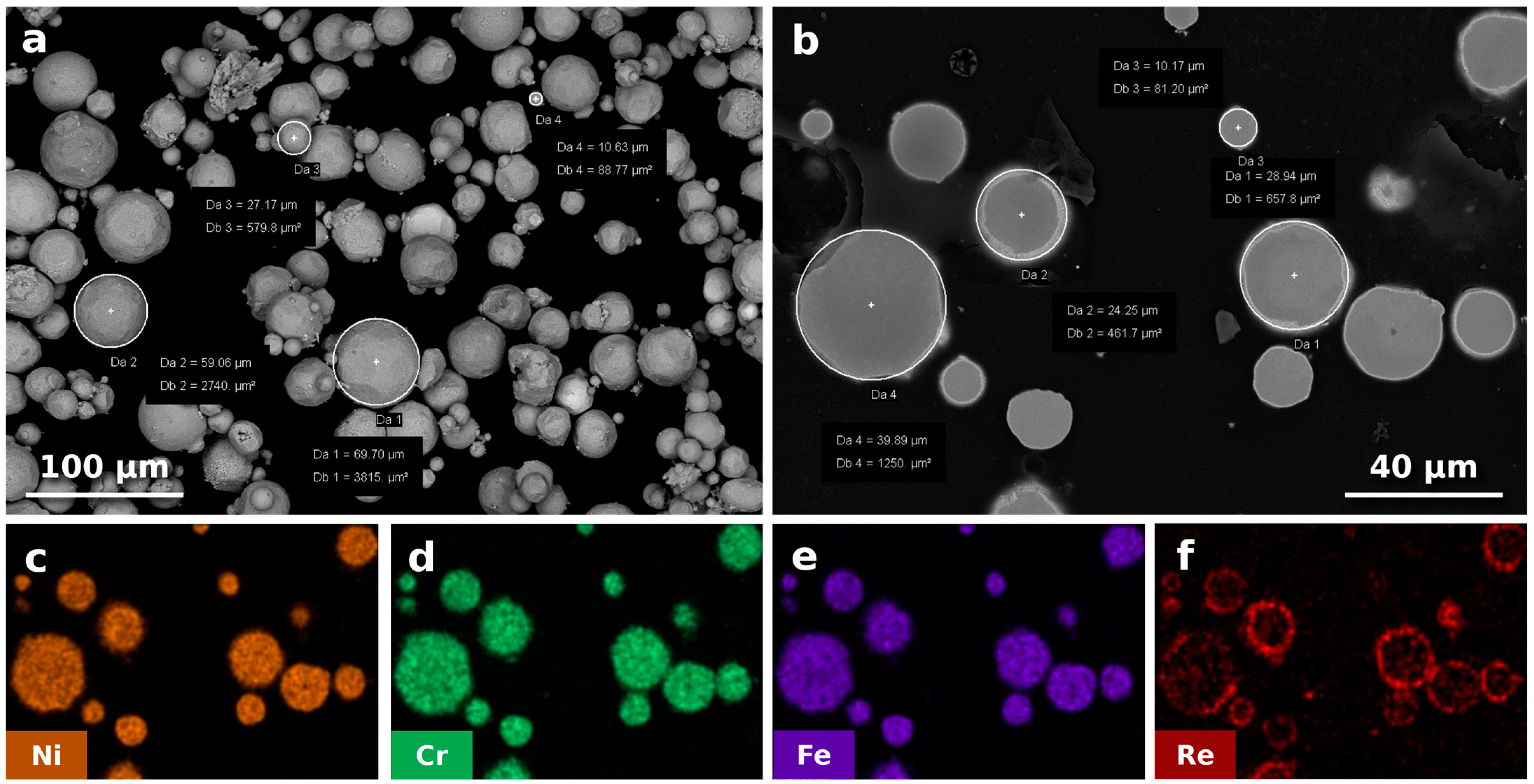
2.1. Powder Preparation
2.2. Sample Fabrication
2.3. Heat Treatment and Hot Isostatic Pressing Post-Treatment
2.4. Material Characterization
2.5. Tensile Test
2.6. Fatigue Test
3. Results
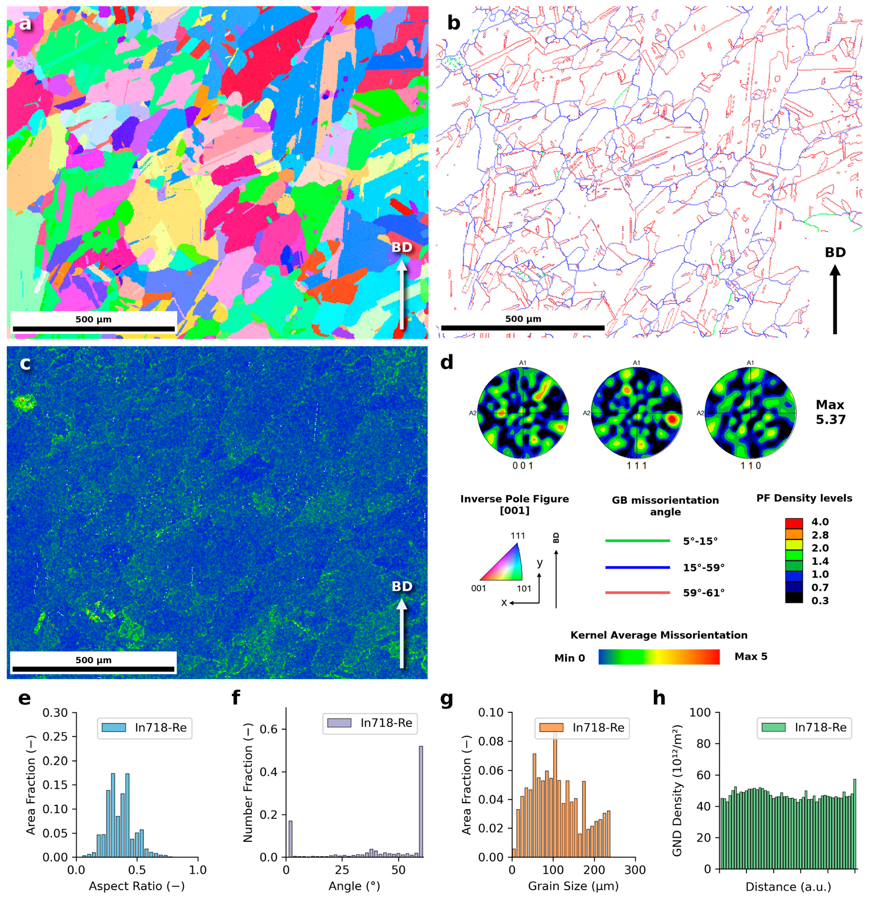
3.1. Microstructure
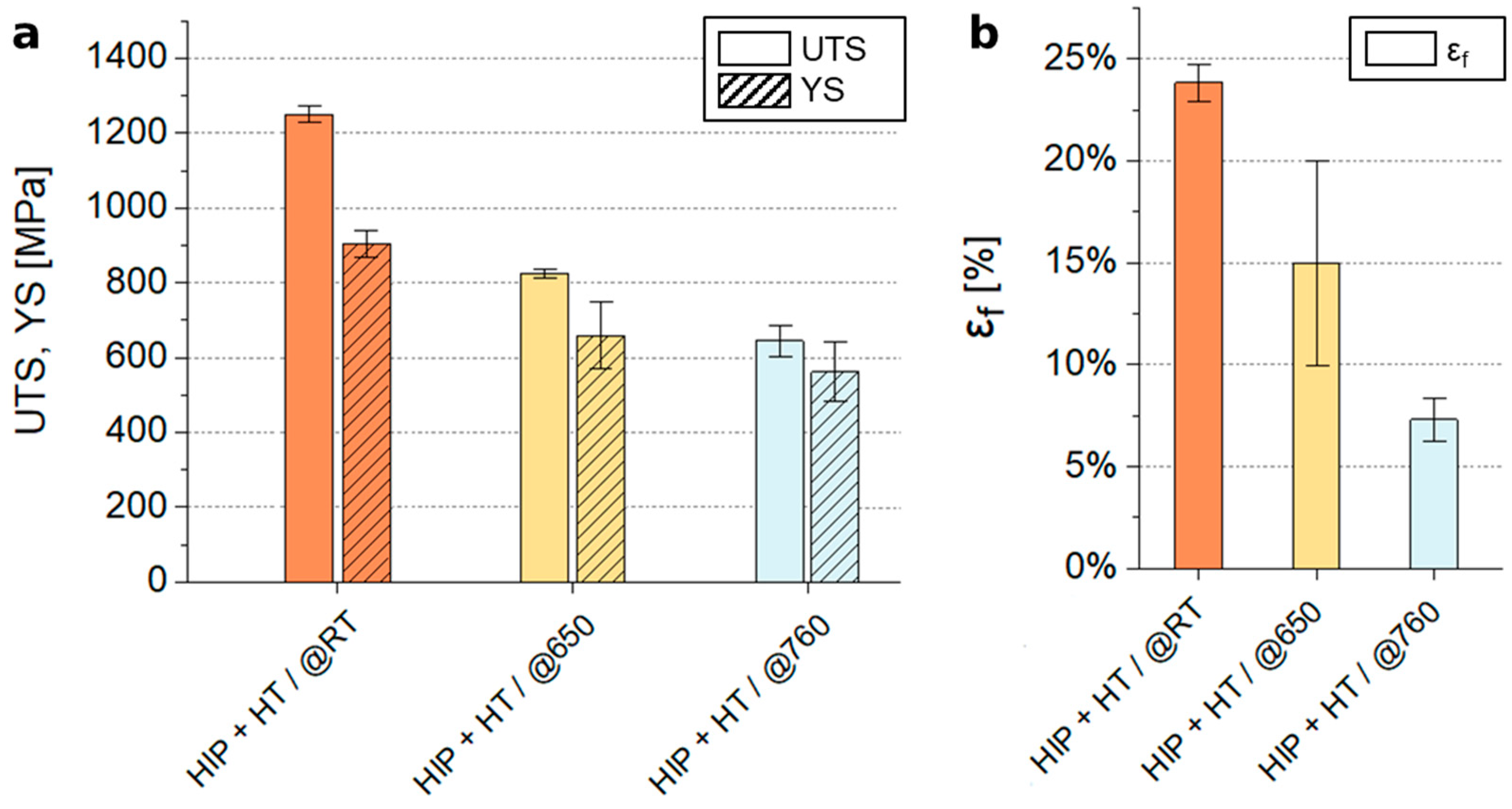
3.2. Tensile Strength
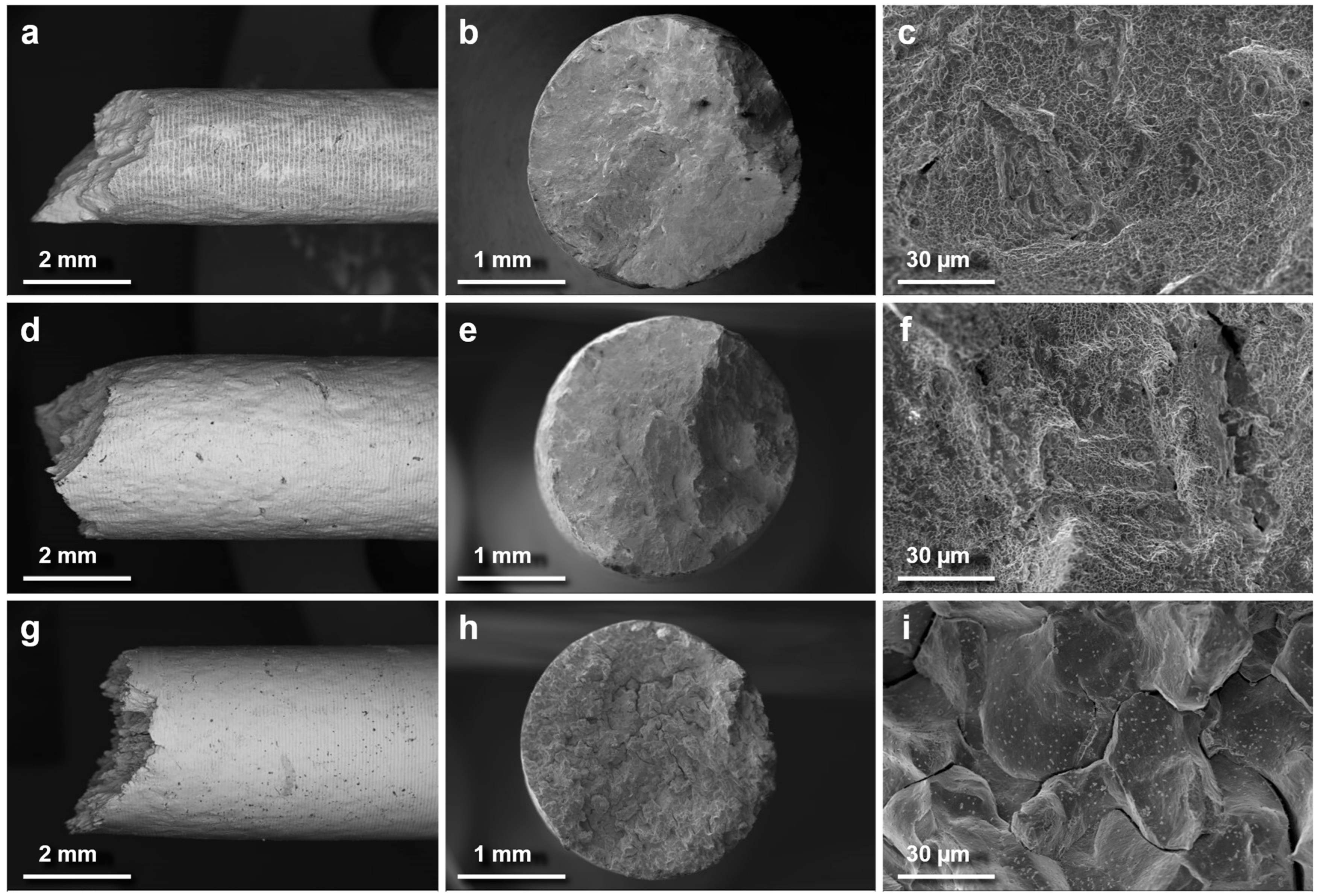
3.3. Fatigue Strength
4. Discussion
5. Conclusions
- The innovative powder surface modification method (Inconel 718 powder alloyed with 3 wt.% rhenium) ensured homogeneous rhenium distribution, effectively mitigating additive segregation and unmelted particle defects commonly observed in powders alloyed via conventional blending.
- The addition of rhenium has been found ineffective for enhancing the mechanical properties or stabilizing the microstructure during service at elevated temperatures. The performance of the alloy decreased significantly above 650 °C, highlighting its limitations for high-temperature applications.
- The results demonstrate that the mechanical properties are primarily governed by the high-temperature post-treatment process, which facilitated a homogenized microstructure and large grain size.
- Near-surface defects and twin boundaries were identified as critical crack initiation sites, emphasizing the necessity for further optimization of PBF-LB/M processing parameters to improve fatigue performance.
Author Contributions
Funding
Institutional Review Board Statement
Informed Consent Statement
Data Availability Statement
Conflicts of Interest
References
- Li, N.; Huang, S.; Zhang, G.; Qin, R.; Liu, W.; Xiong, H.; Shi, G.; Blackburn, J. Progress in additive manufacturing on new materials: A review. J. Mater. Sci. Technol. 2019, 35, 242–269. [Google Scholar] [CrossRef]
- Blakey-Milner, B.; Gradl, P.; Snedden, G.; Brooks, M.; Pitot, J.; Lopez, E.; Leary, M.; Berto, F.; du Plessis, A. Metal additive manufacturing in aerospace: A review. Mater. Des. 2021, 209, 110008. [Google Scholar] [CrossRef]
- Gradl, P.R.; Mireles, O.R.; Protz, C.S.; Garcia, C.P. Metal Additive Manufacturing for Propulsion Applications; American Institute of Aeronautics and Astronautics, Inc.: Reston, VA, USA, 2022. [Google Scholar] [CrossRef]
- Powell, D.; Rennie, A.E.W.; Geekie, L.; Burns, N. Understanding powder degradation in metal additive manufacturing to allow the upcycling of recycled powders. J. Clean. Prod. 2020, 268, 122077. [Google Scholar] [CrossRef]
- Wang, Z.; Guan, K.; Gao, M.; Li, X.; Chen, X.; Zeng, X. The microstructure and mechanical properties of deposited-IN718 by selective laser melting. J. Alloys Compd. 2012, 513, 518–523. [Google Scholar] [CrossRef]
- Li, J.; Liu, W.; Shen, J.; Zhang, X.; Li, S.; Wang, Z. Research progress of the metal powder reuse for powder bed fusion additive manufacturing technology. Powder Technol. 2024, 441, 119815. [Google Scholar] [CrossRef]
- Sadeghi, E.; Karimi, P.; Esmaeilizadeh, R.; Berto, F.; Shao, S.; Moverare, J.; Toyserkani, E.; Shamsaei, N. A state-of-the-art review on fatigue performance of powder bed fusion-built alloy 718. Prog. Mater. Sci. 2023, 133, 101066. [Google Scholar] [CrossRef]
- Gallmeyer, T.G.; Moorthy, S.; Kappes, B.B.; Mills, M.J.; Amin-Ahmadi, B.; Stebner, A.P. Knowledge of process-structure-property relationships to engineer better heat treatments for laser powder bed fusion additive manufactured Inconel 718. Addit. Manuf. 2020, 31, 100977. [Google Scholar] [CrossRef]
- Hosseini, E.; Popovich, V.A. A review of mechanical properties of additively manufactured Inconel 718. Addit. Manuf. 2019, 30, 100877. [Google Scholar] [CrossRef]
- Mostafaei, A.; Ghiaasiaan, R.; Ho, I.T.; Strayer, S.; Chang, K.C.; Shamsaei, N.; Shao, S.; Paul, S.; Yeh, A.-C.; Tin, S.; et al. Additive manufacturing of nickel-based superalloys: A state-of-the-art review on process-structure-defect-property relationship. Prog. Mater. Sci. 2023, 136, 101108. [Google Scholar] [CrossRef]
- Kurzynowski, T.; Smolina, I.; Kobiela, K.; Kuźnicka, B.; Chlebus, E. Wear and corrosion behaviour of Inconel 718 laser surface alloyed with rhenium. Mater. Des. 2017, 132, 349–359. [Google Scholar] [CrossRef]
- Tan, C.; Weng, F.; Sui, S.; Chew, Y.; Bi, G. Progress and perspectives in laser additive manufacturing of key aeroengine materials. Int. J. Mach. Tools Manuf. 2021, 170, 103804. [Google Scholar] [CrossRef]
- Kelbassa, I.; Albus, P.; Dietrich, J.; Wilkes, J. Manufacture and repair of aero engine components using laser technology. In Proceedings of the 3rd Pacific International Conference on Applications of Lasers and Optics, PICALO 2008—Conference Proceedings, Beijing, China, 16–18 April 2008; pp. 208–213. [Google Scholar]
- Gruber, K.; Stopyra, W.; Kobiela, K.; Kohlwes, P.; Čapek, J.; Polatidis, E.; Kelbassa, I. Achieving high strength and ductility in Inconel 718: Tailoring grain structure through micron-sized carbide additives in PBF-LB/M additive manufacturing. Virtual Phys. Prototyp. 2024, 19, e2396064. [Google Scholar] [CrossRef]
- Ho, I.T.; Chen, Y.T.; Yeh, A.C.; Chen, C.P.; Jen, K.K. Microstructure evolution induced by inoculants during the selective laser melting of IN718. Addit. Manuf. 2018, 21, 465–471. [Google Scholar] [CrossRef]
- Ho, I.T.; Hsu, T.H.; Chang, Y.J.; Li, C.W.; Chang, K.C.; Tin, S.; Kakehi, K.; Yeh, A.-C. Effects of CoAl2O4 inoculants on microstructure and mechanical properties of IN718 processed by selective laser melting. Addit. Manuf. 2020, 35, 101328. [Google Scholar] [CrossRef]
- Sun, P.; Wang, D.; Song, W.; Tang, C.; Yang, J.; Xu, Z.; Kakehi, K.; Yeh, A.-C. Influence of W content on microstructure and corrosion behavior of laser cladded Inconel 718 coating. Surf. Coat. Technol. 2023, 452, 129079. [Google Scholar] [CrossRef]
- Liu, G.; Su, Y.; Xin, S.; Li, C.; Deng, Z.; Liu, D.; Kakehi, K.; Yeh, A.-C. Enhanced wear resistance of Ti reinforced Inconel 718 superalloy manufactured by laser directed energy deposition. Mater. Charact. 2024, 209, 113736. [Google Scholar] [CrossRef]
- Yamamoto, T.; Hara, M.; Hatano, Y. Cracking behavior and microstructural, mechanical and thermal characteristics of tungsten–rhenium binary alloys fabricated by laser powder bed fusion. Int. J. Refract. Metals Hard Mater. 2021, 100, 105651. [Google Scholar] [CrossRef]
- Czechowska, K.; Wrona, A.; Mazur, J.; Lis, M.; Tomczyk, P.; Frankiewicz, M.; Bilewska, K.; Osadnik, M.; Weglowski, M.; Dziedzic, R.; et al. Method of Preparing Composite Powder for Bulk Materials and Coatings Produced in Thermal Spraying Processes. PL Patent P.443143, 17 June 2024. [Google Scholar]
- ISO/ASTM 52900:2021; Additive Manufacturing—General Principles—Terminology. International Organization for Standardization and ASTM International: West Conshohocken, PA, USA, 2021.
- ISO/ASTM 52911-1:2020; Additive Manufacturing—Design—Part 1: Laser-Based Powder Bed Fusion of Metals. International Organization for Standardization and ASTM International: West Conshohocken, PA, USA, 2020.
- ASTM E8/E8M-22; Standard Test Methods for Tension Testing of Metallic Materials. ASTM International: West Conshohocken, PA, USA, 2022.
- ASTM E466-21; Standard Practice for Conducting Force Controlled Constant Amplitude Axial Fatigue Tests of Metallic Materials. ASTM International: West Conshohocken, PA, USA, 2021.
- ASTM F3055-14a (2021); Standard Specification for Additive Manufacturing Nickel Alloy (UNS N07718) with Powder Bed Fusion. ASTM International: West Conshohocken, PA, USA, 2021.
- Gruber, K.; Dziedzic, R.; Kuźnicka, B.; Madejski, B.; Malicki, M. Impact of high temperature stress relieving on final properties of Inconel 718 processed by laser powder bed fusion. Mater. Sci. Eng. A 2021, 813, 141111. [Google Scholar] [CrossRef]
- Zhang, D.; Prasad, A.; Bermingham, M.J.; Todaro, C.J.; Benoit, M.J.; Patel, M.N.; Qiu, D.; StJohn, D.H.; Qian, M.; Easton, M.A. Grain Refinement of Alloys in Fusion-Based Additive Manufacturing Processes. Metall. Mater. Trans. A Phys. Metall. Mater. Sci. 2020, 51, 4341–4359. [Google Scholar] [CrossRef]
- Yuan, P.; Gu, D.; Dai, D. Particulate migration behavior and its mechanism during selective laser melting of TiC reinforced Al matrix nanocomposites. Mater. Des. 2015, 82, 46–55. [Google Scholar] [CrossRef]
- Gu, D.; Zhang, H.; Dai, D.; Xia, M.; Hong, C.; Poprawe, R. Laser additive manufacturing of nano-TiC reinforced Ni-based nanocomposites with tailored microstructure and performance. Compos. B Eng. 2019, 163, 585–597. [Google Scholar] [CrossRef]
- Cheng, M.; Lu, Z.; Wu, J.; Guo, R.; Qiao, J.; Xu, L.; Yang, R. Effect of thermal induced porosity on high-cycle fatigue and very high-cycle fatigue behaviors of hot-isostatic-pressed Ti-6Al-4V powder components. J. Mater. Sci. Technol. 2022, 98, 177–185. [Google Scholar] [CrossRef]
- Kelkar, R.; Andreaco, A.; Ott, E.; Groh, J. Alloy 718: Laser Powder Bed Additive Manufacturing for Turbine Applications. In Proceedings of the 9th International Symposium on Superalloy 718 & Derivatives, Pittsburgh, PA, USA, 3–6 June 2018; pp. 53–68. [Google Scholar]
- Gruber, K.; Stopyra, W.; Kobiela, K.; Madejski, B.; Malicki, M. Mechanical properties of Inconel 718 additively manufactured by laser powder bed fusion after industrial high-temperature heat treatment. J. Manuf. Process. 2022, 73, 642–659. [Google Scholar] [CrossRef]
- Miao, J.; Pollock, T.M.; Wayne Jones, J. Microstructural extremes and the transition from fatigue crack initiation to small crack growth in a polycrystalline nickel-base superalloy. Acta Mater. 2012, 60, 2840–2854. [Google Scholar] [CrossRef]
- AMS 5383F; Nickel Alloy, Corrosion and Heat-Resistant, Investment Castings 52.5Ni-19Cr-3.0Mo-5.1Cb(Nb)-0.90Ti-0.60Al-18Fe Vacuum Melted Homogenization and Solution Heat Treated. SAE International: Warrendale, PA, USA, 2023. [CrossRef]
- Huang, L.; Cao, Y.; Zhang, J.; Gao, X.; Li, G.; Wang, Y. Effect of heat treatment on the microstructure evolution and mechanical behaviour of a selective laser melted Inconel 718 alloy. J. Alloys Compd. 2021, 865, 158613. [Google Scholar] [CrossRef]
- AMS 5663P; Nickel Alloy, Corrosion- and Heat-Resistant, Bars, Forgings, Rings, and Stock for Forgings and Rings, 52.5Ni-19Cr-3.0Mo-5.1Cb (Nb)-0.90Ti-0.50Al-18Fe, Consumable Electrode or Vacuum Induction Melted, 1775 °F (968 °C) Solution and Precipitation Heat Treated. SAE International: Warrendale, PA, USA, 2022. [CrossRef]
- Amato, K.N.; Gaytan, S.M.; Murr, L.E.; Martinez, E.; Shindo, P.W.; Hernandez, J.; Collins, S.; Medina, F. Microstructures and mechanical behavior of Inconel 718 fabricated by selective laser melting. Acta Mater. 2012, 60, 2229–2239. [Google Scholar] [CrossRef]
- Schafrik, R.E.; Ward, D.D.; Groh, J.R. Application of alloy 718 in GE aircraft engines: Past, present and next five years. Proc. Int. Symp. Superalloys Var. Deriv. 2011, 1, 1–11. [Google Scholar] [CrossRef]
- Tekoğlu, E.; O’Brien, A.D.; Bae, J.S.; Lim, K.H.; Liu, J.; Kavak, S.; Zhang, Y.; Kim, S.Y.; Ağaoğulları, D.; Chen, W.; et al. Metal matrix composite with superior ductility at 800 °C: 3D printed In718+ZrB2 by laser powder bed fusion. Compos. Part. B Eng. 2024, 268, 111052. [Google Scholar] [CrossRef]
- Ziółkowski, G.; Gruber, K.; Tokarczyk, E.; Roszak, R.; Ziegenhorn, M. X-ray Computed Tomography for the ex-situ mechanical testing and simulation of additively manufactured IN718 samples. Addit. Manuf. 2021, 45, 102070. [Google Scholar] [CrossRef]
- Kindrachuk, V.; Wanderka, N.; Banhart, J.; Mukherji, D.; Genovese D del Rösler, J. Effect of rhenium addition on the microstructure of the superalloy Inconel 706. Acta Mater. 2008, 56, 1609–1618. [Google Scholar] [CrossRef]
- Zhang, J.; Huang, T.; Lu, F.; Cao, K.; Wang, D.; Zhang, J.; Su, H.; Liu, L. The effect of rhenium on the microstructure stability and γ/γ′ interfacial characteristics of Ni-based single crystal superalloys during long-term aging. J. Alloys Compd. 2021, 876. [Google Scholar] [CrossRef]
- Kawagoishi, N.; Chen, Q.; Nisitani, H. Fatigue strength of Inconel 718 at elevated temperatures. Fatigue Fract. Eng. Mater. Struct. 2000, 23, 209–216. [Google Scholar] [CrossRef]
- Davis, J.R. AMS Speciality Handbook: Heat-Resistant Materials; AMS International: Materials Park, OH, USA, 1997. [Google Scholar]
- Zhou, L.; Chen, S.; Zhang, C.; Liang, J.; Cui, T.; Liu, C.; Wang, M. Microstructure evolution and properties of direct laser deposited 24CrNiMoY alloy steel assisted by non-contact ultrasonic treatment. Mater. Sci. Eng. A 2021, 811, 141088. [Google Scholar] [CrossRef]
- Wang, H.; Hu, Y.; Ning, F.; Cong, W. Ultrasonic vibration-assisted laser engineered net shaping of Inconel 718 parts: Effects of ultrasonic frequency on microstructural and mechanical properties. J. Mater. Process. Technol. 2020, 276, 116395. [Google Scholar] [CrossRef]
- Huang, L.; Zhou, J.; Xu, J.; Huo, K.; He, W.; Meng, X.; Huang, S. Microstructure and wear resistance of electromagnetic field assisted multi-layer laser clad Fe901 coating. Surf. Coat. Technol. 2020, 395, 125876. [Google Scholar] [CrossRef]
- Lu, F.; Lu, S.; Antonov, S.; Li, L.; He, S.; Hou, M.; Wang, D.; Zhang, J.; Feng, Q. Duration-affected creep behaviors of Ni-based single crystal superalloys with/without rhenium addition designed for IGT application. Mater. Sci. Eng. A 2023, 864, 144560. [Google Scholar] [CrossRef]


| Specimen Group | Post-Treatment | Sample Geometry /Finishing Standard | Test |
|---|---|---|---|
| HIP + HT/@RT | HIP + solution annealing + double aging | ASTM E8/E8M-22 | static tensile test, room temp. |
| HIP + HT/@650 | static tensile test, 650 °C (1200 F) | ||
| HIP + HT/@760 | static tensile test, 760 °C (1400 F) | ||
| HIP + HT | ASTM E466 | fatigue test, room temp. |
Disclaimer/Publisher’s Note: The statements, opinions and data contained in all publications are solely those of the individual author(s) and contributor(s) and not of MDPI and/or the editor(s). MDPI and/or the editor(s) disclaim responsibility for any injury to people or property resulting from any ideas, methods, instructions or products referred to in the content. |
© 2025 by the authors. Licensee MDPI, Basel, Switzerland. This article is an open access article distributed under the terms and conditions of the Creative Commons Attribution (CC BY) license (https://creativecommons.org/licenses/by/4.0/).
Share and Cite
Frankiewicz, M.; Karoluk, M.; Dziedzic, R.; Gruber, K.; Stopyra, W. Static and Fatigue Properties of Rhenium-Alloyed Inconel 718 Produced by Powder Bed Fusion Additive Manufacturing. Materials 2025, 18, 692. https://doi.org/10.3390/ma18030692
Frankiewicz M, Karoluk M, Dziedzic R, Gruber K, Stopyra W. Static and Fatigue Properties of Rhenium-Alloyed Inconel 718 Produced by Powder Bed Fusion Additive Manufacturing. Materials. 2025; 18(3):692. https://doi.org/10.3390/ma18030692
Chicago/Turabian StyleFrankiewicz, Mariusz, Michał Karoluk, Robert Dziedzic, Konrad Gruber, and Wojciech Stopyra. 2025. "Static and Fatigue Properties of Rhenium-Alloyed Inconel 718 Produced by Powder Bed Fusion Additive Manufacturing" Materials 18, no. 3: 692. https://doi.org/10.3390/ma18030692
APA StyleFrankiewicz, M., Karoluk, M., Dziedzic, R., Gruber, K., & Stopyra, W. (2025). Static and Fatigue Properties of Rhenium-Alloyed Inconel 718 Produced by Powder Bed Fusion Additive Manufacturing. Materials, 18(3), 692. https://doi.org/10.3390/ma18030692