Article

Effects of Laser Shock Processing on the Mechanical Properties of 6061-T6 Aluminium Alloy Using Nanosecond and Picosecond Laser Pulses

by
Martha Guadalupe Arredondo Bravo
1,
Gilberto Gomez-Rosas
1,*,
Miguel Morales
2,
David Munoz-Martin
2,
Juan Jose Moreno-Labella
2,
Jose Manuel Lopez Lopez
2,
Jose Guadalupe Quiñones Galvan
1,
Carlos Rubio-Gonzalez
3,
Francisco Javier Casillas Rodriguez
4 and
Carlos Molpeceres
2
1
Centro Universitario de Ciencias Exactas e Ingenierías, Universidad de Guadalajara, Blvd. Marcelino García Barragán 1421, esq. Calzada Olímpica, Guadalajara 44430, Jalisco, Mexico
2
Centro Laser, Universidad Politécnica de Madrid, C/Alan Turing 1, 28038 Madrid, Spain
3
Escuela de Ingenieria y Ciencias, Tecnologico de Monterrey, Epigmenio González 500 Fracc, San Pablo 76130, Querétaro, Mexico
4
Centro Universitario de los Lagos, Universidad de Guadalajara, Av. Enrique Díaz de León 1144, Colonia Paseos de la Montaña, Lagos de Moreno 47460, Jalisco, Mexico
*
Author to whom correspondence should be addressed.
Materials 2025, 18(20), 4649; https://doi.org/10.3390/ma18204649
Submission received: 9 September 2025 / Revised: 26 September 2025 / Accepted: 29 September 2025 / Published: 10 October 2025
(This article belongs to the Special Issue Advances in Laser Processing Technology of Materials—Second Edition)

Abstract

Laser shock processing (LSP) is a surface treatment technique used to enhance mechanical properties such as hardness, corrosion resistance, and wear resistance. This study investigates the effects of LSP on a 6061-T6 aluminium alloy using four treatment conditions: nanosecond (ns-LSP), picosecond (ps-LSP), and a combination of nanosecond–picosecond (nsps-LSP) and picosecond–nanosecond (psns-LSP) pulses. Two laser systems were employed: a Q-switched Nd:YAG laser (850 mJ/pulse, 6 ns, 1064 nm, 10 Hz), and an Ekspla Atlantic 355-60 laser (0.110 mJ/pulse, 13 ps, 1064 nm, 1 kHz). All treatments induced compressive residual stresses up to 1 mm in depth. Additionally, improvements in microhardness were observed, particularly at deeper layers in the combined nsps-LSP treatment. Surface roughness was measured and compared. Among all configurations, the nsps-LSP treatment produced the highest compressive residual stresses (−428 MPa) and greater microhardness at depth. These results suggest that the combined nsps-LSP treatment represents a promising approach to enhance the mechanical performance of metallic components.

1. Introduction

Aluminium alloy 6061-T6 is widely used in various industries that require forming processes, especially extrusion, such as orthopaedic devices, turbine blades, rods, and gears, among other components that need low weight, corrosion resistance, hardness, and wear resistance [1,2]. Due to exposure to wear processes, aluminium materials suffer deterioration in their mechanical properties, such as fatigue resistance, wear resistance, and hardness. Over time, different techniques have been investigated to improve these properties, including laser shock peening (LSP) and conventional shock peening (SP).
Since 1962, Askaryan and Moroz studied the effect of the pressure exerted on the surface by a laser pulse. In 1974 Fairand and Mallozzi obtained the first patent for laser shock treatment (LSP). This innovative surface treatment technique improved the mechanical properties of materials by generating residual compressive stresses on the treated surface [3,4,5,6]. This process generates shock waves that help to improve mechanical properties such as fatigue, corrosion, and wear resistance [7], in addition to achieving a better surface finish compared to other surface treatments.
In previous works, Gómez-Rosas et al. (2010) [8] and He et al. (2021) [9] have shown that traditional nanosecond LSP (ns-LSP) surface treatment improves the mechanical properties of aluminium alloys. High compressive residual stress values extending to depths close to 1 mm were reported in [8]. Petronic et al. (2017) [10] applied picosecond LSP (ps-LSP) to a Nimonic 263 alloy, demonstrating an increase in microhardness near the surface, which gradually decreases with depth up to approximately 1 mm. They concluded that this is a good alternative for improving the mechanical properties of materials [10]. Keshavarz et al. (2016) induced residual stresses in a silicon biotemplate using an ultrashort pulse laser (USPL) in the femtosecond range, which caused silicon recrystallization [11]. In 2020, Rujian Sun et al. compared combined nano and femtosecond LSP treatments and found that the hardness at the nano-depth was higher in the femto-nanosecond combination, which they attributed to better laser absorption and strong plastic deformation [12]. In 2020, Loja, and in 2022, Lopez J., performed laser peen forming with a picosecond laser and achieved curved deformations, avoided wear, and induced residual compressive stresses [13,14]. Recently, Hu et al. (2025) showed the corrosion behaviour of laser powder bed fusion TA2-Cu-Q345 composite plate subjected to picosecond LSP, obtaining improved corrosion resistance in the treated samples [15].
Since each LSP pulse covers a small area, pulses are overlapped and scanned in a zigzag pattern to ensure full coverage. However, this induces residual stress anisotropy, leading to variations in stress magnitude between the x- and y-directions on the surface. This effect has been observed experimentally [8,16] and predicted in numerical simulations [16,17]. Additionally, Correa et al. (2015) demonstrated through simulations of LSP treatments that using random scanning patterns significantly reduces residual stress anisotropy, compared to the conventional LSP zigzag pattern [17].
LSP is based on the interaction between laser and matter. This phenomenon begins when a high-energy pulsed laser beam strikes the surface of the material; the beam is concentrated with a lens, resulting in a large amount of energy per unit area, vaporising part of the material, and simultaneously generating a plasma (ionised gas) that expands rapidly. The expansion of the plasma occurs in the opposite direction to the incidence of the laser pulse, creating a pressure of the order of GPa on the surface of the material. This creates a shock wave that propagates through the bulk, causing both elastic and plastic deformations, which contributes to the generation of stresses in the same direction of wave propagation, as shown in Figure 1. LSP treatments without a sacrificial layer (LSPwC) were used in this work [18].
In this study, 6061-T6 aluminium alloy samples were used, the LSP treatment was performed with picosecond and nanosecond lasers and combinations of both, and residual stresses were analysed before and after treatment. A wavelength of 1064 nm was used for both treatments. When combining treatments, the same scan direction was used for both processes. After treatment, residual stress tests using the hole-drilling method and microhardness measurements using a Vickers indenter and contact profilometry were performed to determine the roughness of the material.

2. Materials and Methods

2.1. Preparation of Samples Before Treatment

The 6061-T6 aluminium alloy target was used; this contains 96–99% aluminium and the rest of the elements that compose the alloy are shown in Table 1 [13].
The sheet has a thickness of 7 mm and was cut into targets with dimensions of 50 mm × 50 mm. A polishing process was performed on the face to be treated, until a semi-mirror finish was obtained. The objective of this process is to eliminate scratches and to have homogeneity in the surface to be treated.

2.2. Experimental Setups and Mechanical Characterizations

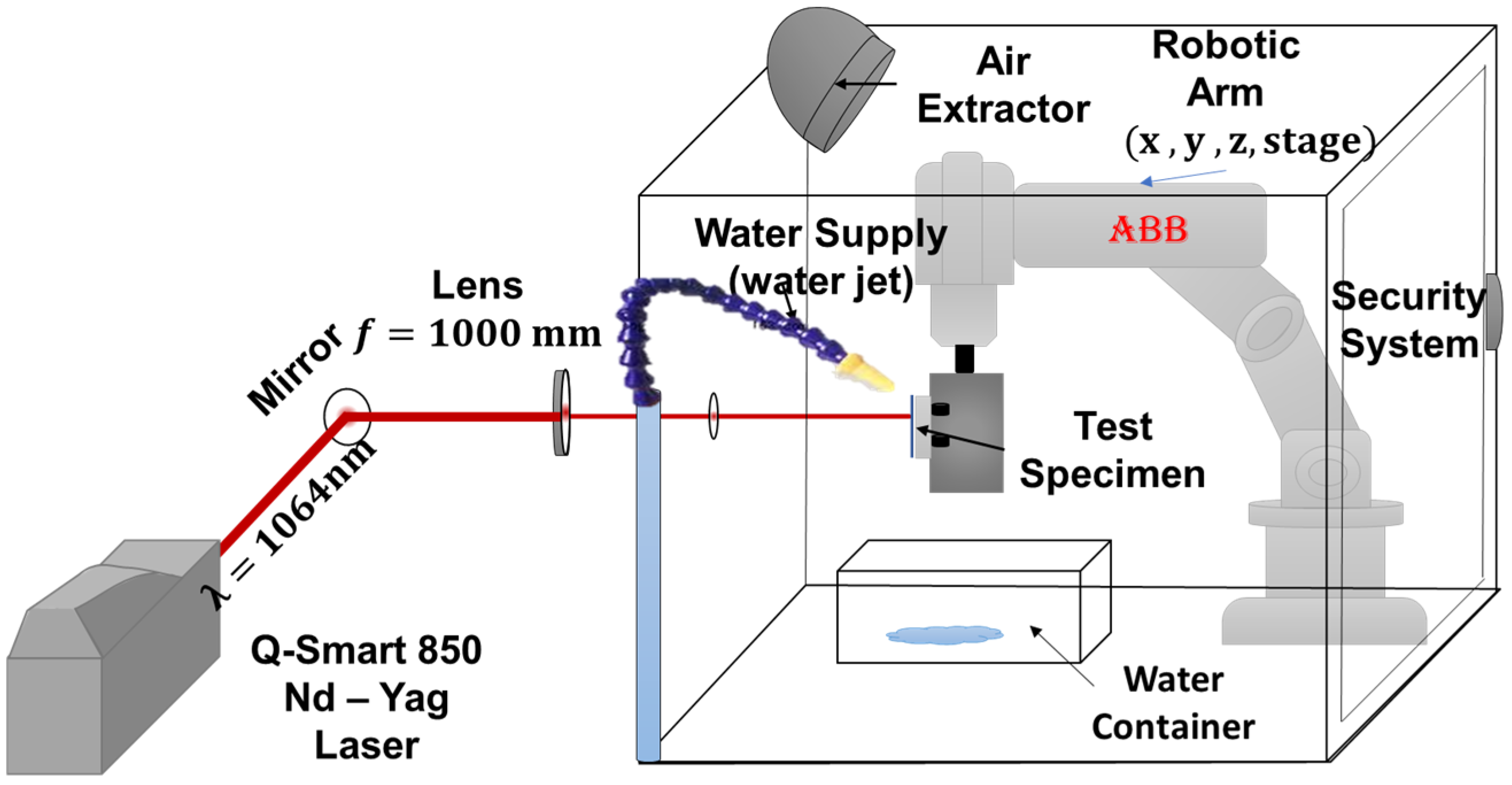
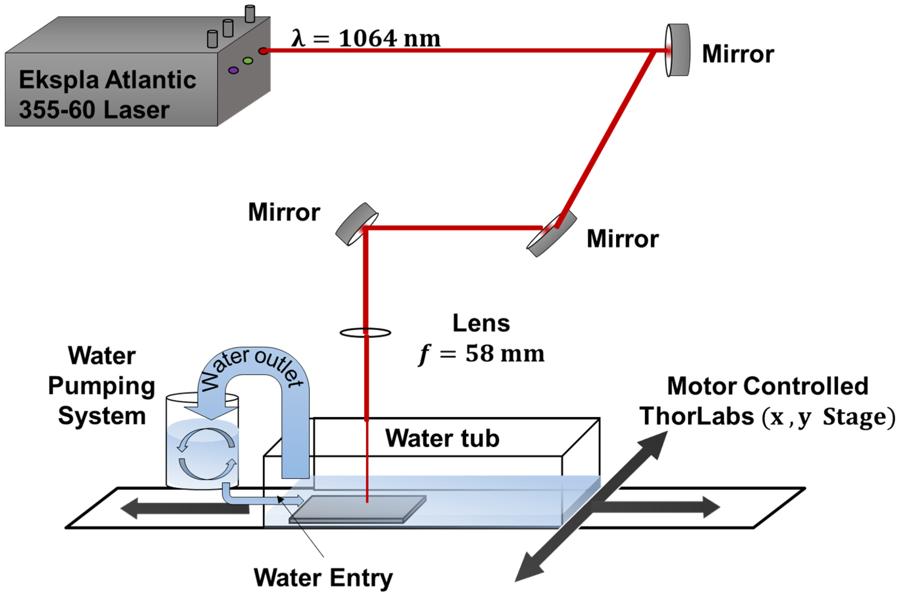
Two different experimental arrangements were used: one with water jet supply to the surface to be treated for the ns-LSP treatment, and the other experimental arrangement was with a confined ablation in cube full for the ps-LSP treatment. Both arrangements are shown in Figure 1.
Two different types of pulsed lasers were used; for the ns laser (Figure 2), a Nd-YAG Quantel Q-Smart 850 laser was used, emitting in nanosecond (ns) by a flash-lamp, with a repetition rate of 10 Hz, energy output of 850 mJ, and a beam output diameter of 9 mm. A lens with a focal length of f = 1000 mm was used to obtain a spot diameter of 1 mm to concentrate the energy and obtain GW/cm2 power densities. The parameters used for the ns-LSP treatment are shown in Table 2. The movement was performed by means of a robotic arm model IRB-120 ABB, with ( x , y , z ) movements.
For the ps laser, an Ekspla Atlantic 355-60 laser was used, with repetition rates of 1–20 × 103 Hz, energy output of 0.110 mJ, and a spot diameter of 4.9 × 10⁻³ cm. Both lasers operated at a wavelength of 1064 nm. The experimental setup was used with the full cube configuration, as can be seen in Figure 3. The optical path is composed of mirrors to direct the beam towards a lens with a focal length of 58 mm; when passing through the lens, the energy is concentrated to generate power densities of GW/cm2, and to irradiate the piece. To perform the movement of the target, a system of x , y motors was used. The water was kept in a continuous rotation with a pump, to avoid the accumulation of residues in the water of the tank. The laser parameters used to perform the treatment can be seen in Table 2.
To ensure high energy transmission in both systems, the optical components are coated with an anti-reflection coating (AR) suitable for the wavelength used.
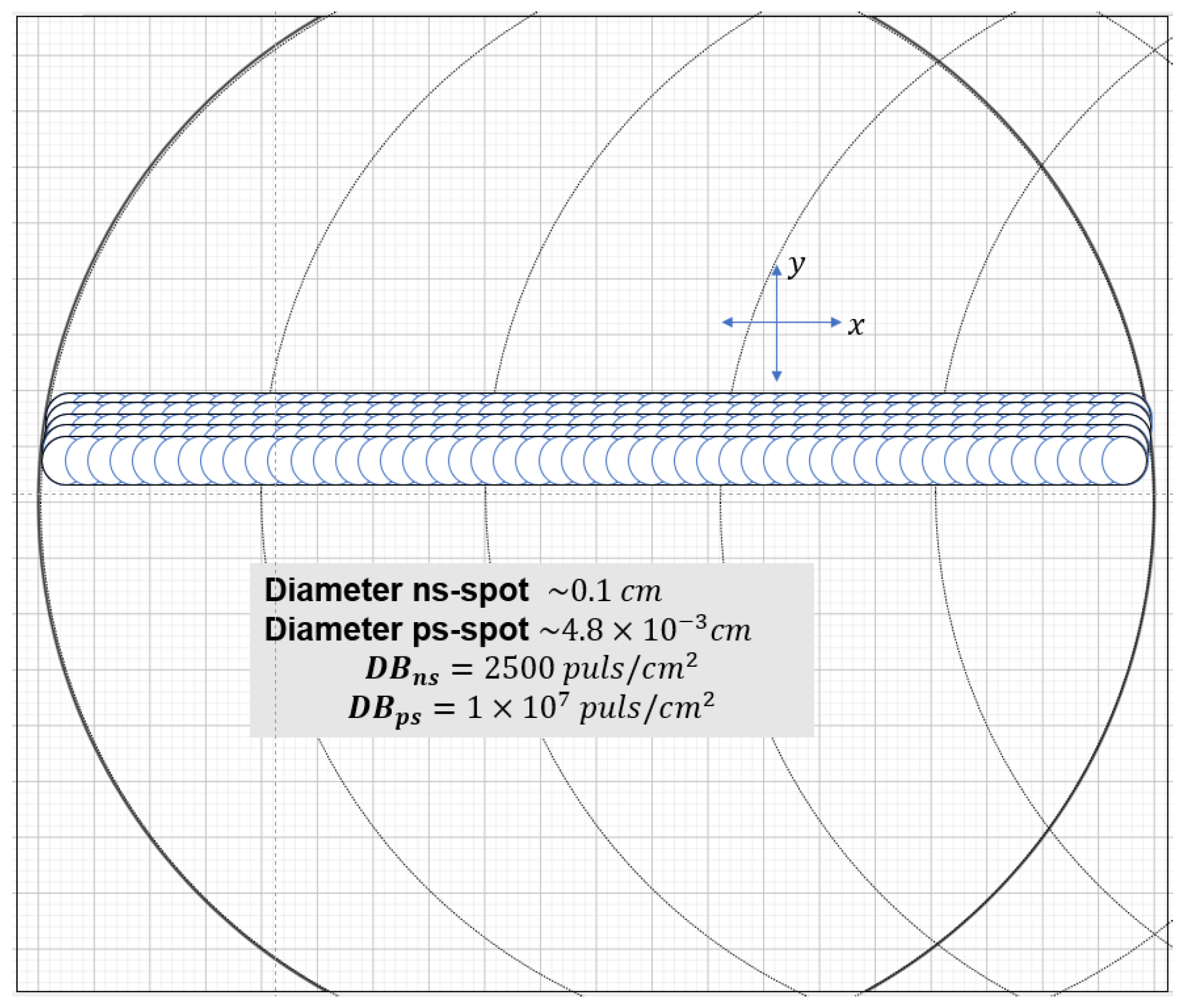
The treated area with ns-LSP treatment was 25 mm × 25 mm, with a pulse density of 2500 pulses/ cm2. We worked with a spot size of 1 mm diameter and an energy of ~0.725 J. The power density obtained was 1.2 × 10¹⁰ W/cm2.
For the ps-LSP experiment, the treatment area was 20 mm × 20 mm. Pulse density were used, 1 × 10⁷ and 2 × 10⁶ pulses/cm2 were used. The spot size had a diameter of 4.80 × 10⁻³ cm, with an energy per pulse of 1.15 × 10⁻⁴ J. This results in a power density of 4.89 × 10¹¹ W/cm2.
Treatment was also performed by combining both sweeps of the two systems, combining the nano–pico (nsps-LSP) and pico–nano (psns-LSP) treatment. In Figure 4, we can see the comparison of laser spot size between ns-LSP and ps-LSP. A total of four different treatments were performed, as shown in Table 3.
The residual stress (RS) was determined using the hole drilling technique. The equipment used for this procedure was the Vishay RS-200 (Milling Guide, Wendell, NC, USA) and the model CEA-06-062UL-120 strain gauge, which was mounted in the same direction as the LSP scan. The parameters used to determine the residual stresses were Young’s modulus (E = 68.9 GPa) and Poisson’s ratio (μ = 0.33). A mathematical algorithm based on ASTM E837-01 [19,20,21] was used to determine the residual stresses.
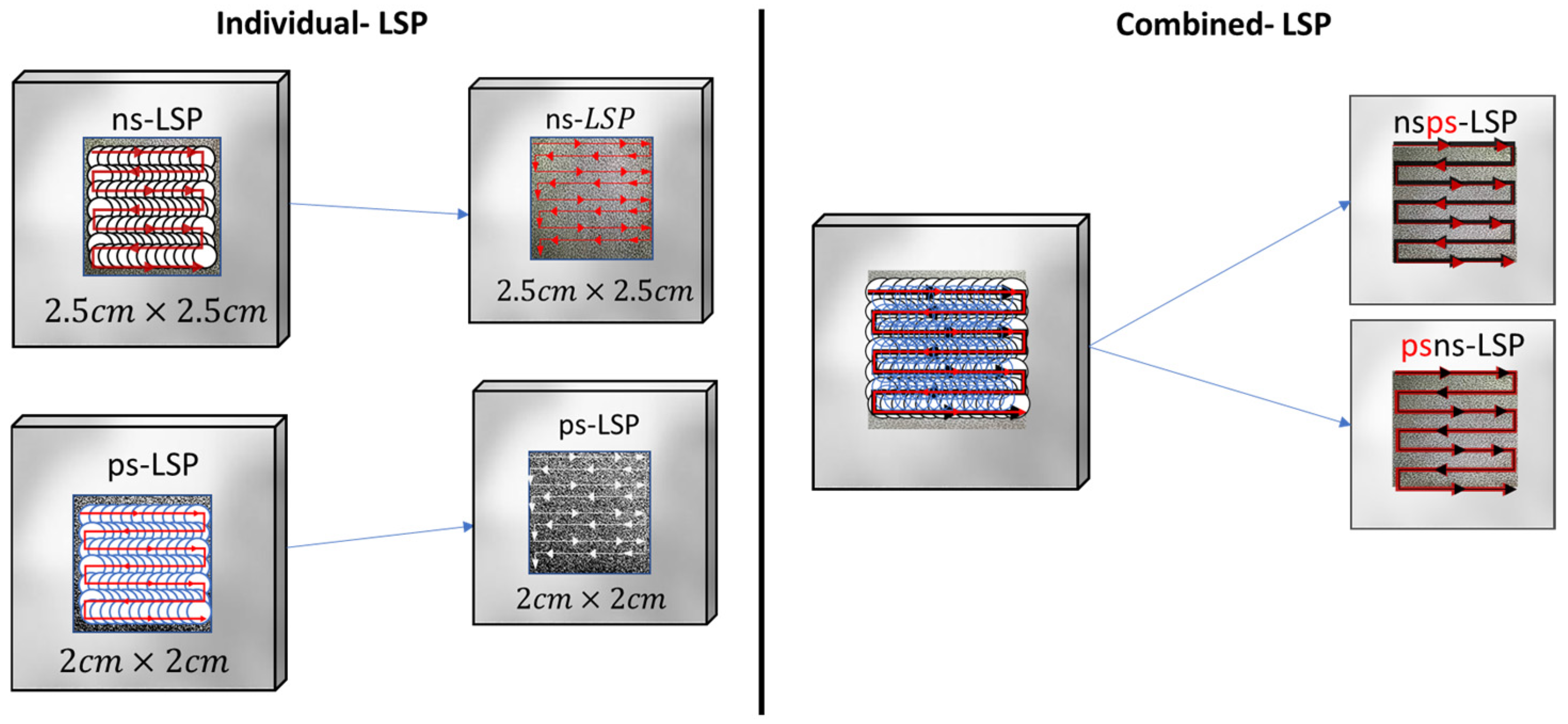
In Figure 5, we can see a graphical representation of the sweep direction of the individual treatments in the same direction for both cases. In the combined treatments, the black arrow indicates the sweep direction of the ns-LSP treatment and the red arrows indicate the sweep direction of the ps-LSP treatment, both in the same direction.
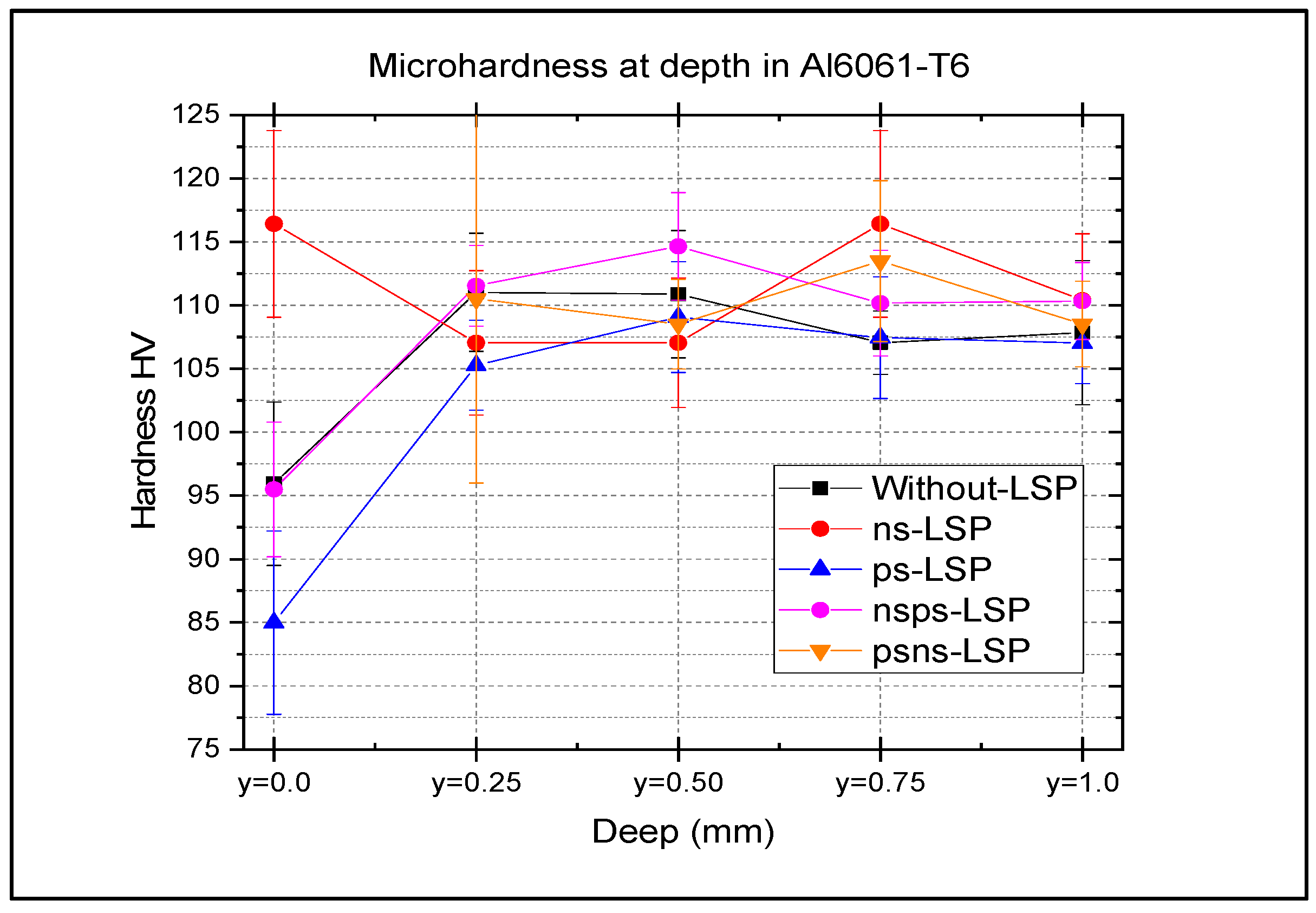
The evaluation of depth microhardness was performed using a MXT30 microhardness tester,(Matsuzawa Co., Ltd., Akita, Japan) following the specifications of ASTM E384. For depth characterisation, the samples were sectioned transversely, and 15 measurements were taken at each depth level, with reference positions set at Y 0 = 0   m m , followed by Y 1 = 0.25   m m , Y 2 = 0.50   m m , Y 3 = 0.75   m m , and Y 4 = 1.00   m m . A total of 15 measurements were performed on each sample.
Finally, roughness tests were performed using a surface contact profilometer with DEKTAK 150 equipment (Veeco Instruments Inc., Plainview, NY, USA). The parameters used for the measurements were a load of 4 mg, a resolution of 0.056   μ m , a measurement range of 6.5   μ m , and a tip radius of 2.5   μ m . Five repetitions per sample were carried out to finally obtain an average roughness (Ra).

3. Results

3.1. Residual Stresses (RS) Results

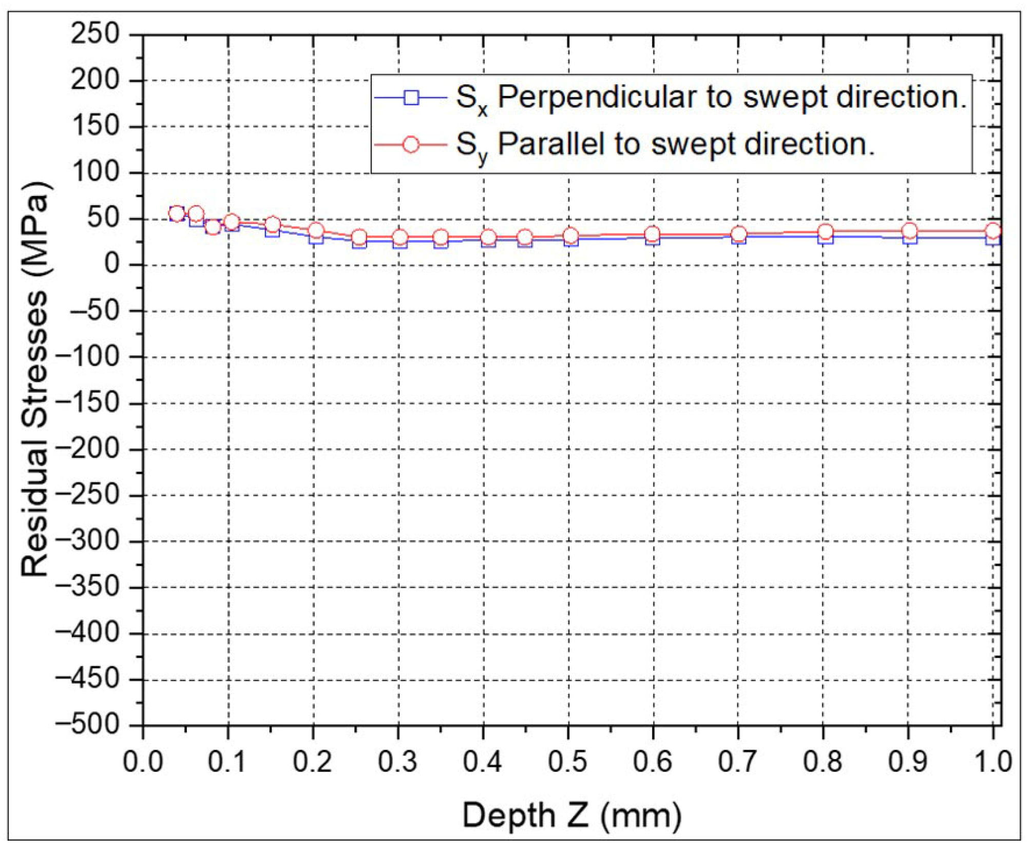
The RS versus depth were measured using the hole drilling method to a depth of 1 mm in all the samples of the Al6061-T6 alloy. In Figure 6, the RS in the sample without LSP treatment is shown, where “Sy” and “Sx” represent the RS, parallel, and perpendicular to the swept direction, respectively. It can be observed that both RS values are tensile, and very similar in value, being between 25 and 60 MPa, and from 0 to 1 mm in depth. These stresses are due to the polishing process prior to the LSP treatment of the 6061-T6 aluminium alloy.
The RS profiles for the individual ns-LSP and ps-LSP treatments are shown in Figure 7 and Figure 8. In the specimen with ns-LSP treatment with a pulse density of 2500 pulses/cm2 (Figure 7) the highest compressive residual stresses are found, both in the direction parallel and perpendicular to the sweep. In the first 0.05 mm of depth, in the RS parallel to the scanning direction tensile RS are observed; however, it can be observed that at a depth between 0.8 and 1.0 mm, compressive RS between −350 and −400 MPa are obtained in the perpendicular direction, and in the parallel direction, between −200 and −150 MPa compressive RS are found at the same depth.
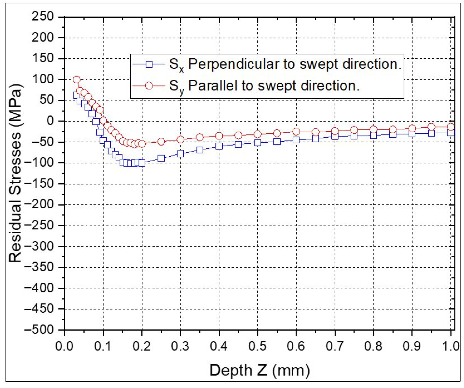
When comparing the ps-LSP treatments (Figure 8), which have a pulse density of 1 × 10⁷ pulses/cm2, the highest compressive RS are −100 MPa in the perpendicular direction and −55 MPa for the parallel direction at a depth of 0.18 mm. The RS values in both directions show less variation between points in the ps-LSP treatments compared to the ns-LSP points in the individual treatments.
In the samples with combined treatments, two different sequences were applied: one where the ps-LSP treatment was performed first, followed by ns-LSP, and another where ns-LSP was applied first, followed by ps-LSP. Each combination was tested using the same pulse density for ns-LSP and ps-LSP treatments.
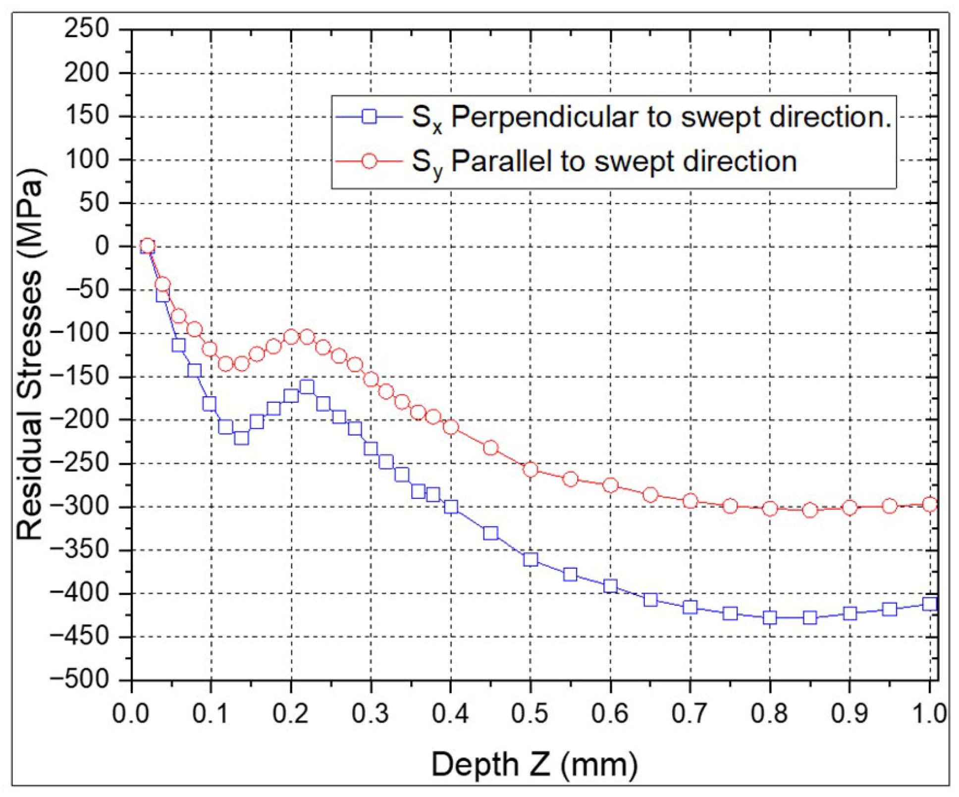
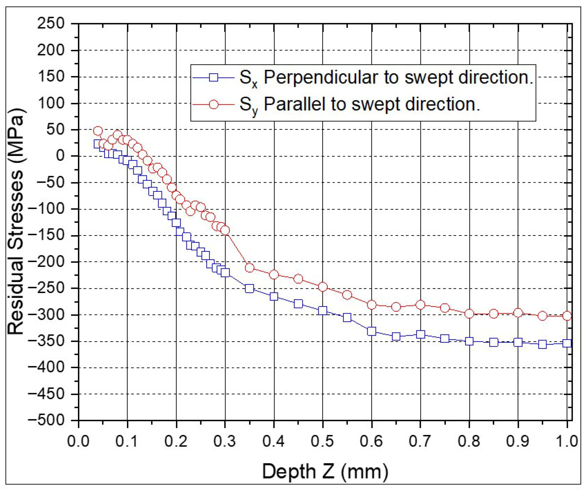
Figure 9 and Figure 10 show the RS values of the combinations with ns-LSP and ps-LSP treatment. The profile shows that the RS value perpendicular to the sweep direction is 50% lower for the psns-LSP combination compared to nsps-LSP. The parallel RS values are similar in both curves.
In Figure 9, the highest compressive residual stresses are observed in the direction perpendicular to the sweep of −428 MPa and for the parallel direction of −304 MPa for the nsps-LSP treatment at a depth of 0.85 mm; the tensile RS are 1.05 MPa at a depth of 0.02 mm and only in the direction parallel to the sweep. For the psns-LSP treatment, shown in Figure 10, the highest compressive RS are −356 MPa in the perpendicular direction and −302 MPa in the parallel direction at a depth of 0.95 mm; tensile RS between 50 and 100 MPa is observed in the first micrometres of depth. Table 4 shows the maximum compressive residual stress values obtained for each treatment as a function of depth.

3.2. Microhardness Results

Figure 11 shows the microhardness profiles as a function of depth (up to 1 mm) for the four treatments compared to the untreated sample. The maximum microhardness values with respect to depth are as follows: with ns-LSP, it can be seen that at a depth of 0.75 mm, the microhardness value is ~116 HV. In the sample treated with ps-LSP, there is no increase in microhardness with depth. The microhardness profiles in the nsps-LSP treatment combination show that at a depth of 0.25 mm, the microhardness values are ~115 HV. The microhardness profiles in the psns-LSP treatment combination show that at a depth of 0.25 mm, the microhardness values are ~113 HV.

3.3. Roughness

Table 5 shows the roughness profiles by contact profilometer; here it can be observed that the values both parallel and perpendicular to the scanning direction for each of the treatments are very similar. The roughness values after treatment are between 6.3 μ m and 12.1 μ m , where it can be observed that in ps-LSP the lowest increase is obtained with respect to the base specimen and the highest increase in roughness is found in the specimen treated with psns-LSP of 12.1   μ m .

4. Discussion

The residual stress values obtained from the ns-LSP treatment are in good agreement with previously reported data, confirming the reliability of our experimental approach [8,19]. In contrast, the ps-LSP treatment led to significantly lower residual stresses. This difference can be attributed to the distinct ablation and interaction mechanisms involved: while the ns regime is predominantly thermally driven, the ps regime combines thermal and electronic processes, which in turn influence the generation and propagation of shock waves.
Regarding the residual stress curves in the parallel and perpendicular directions obtained in the combined treatments (nsps-LSP, psns-LSP), a significant reduction in their separation is observed when compared to the traditional ns-LSP treatment. This behaviour may be attributed to the anisotropy phenomenon reported in [16]. In conventional treatments, the decrease in Sx is typically associated with the tensile stress introduced by the overlap of consecutive laser pulse columns in the x-direction. However, in ps-LSP treatments, the reduced overlap minimises this effect, leading to a modified stress distribution that influences the subsequent ns-LSP treatment. This phenomenon will be further investigated in future work.
In terms of microhardness, the ps-LSP treatment yielded the lowest values, even lower than those of the base material. This behaviour may be explained by the nature of the energy–matter interaction, the high repetition rate, and the surface effects induced by the ultrashort (ps) laser pulses [22,23]. In contrast, the highest microhardness values were obtained with the nsps-LSP treatment at depths of 0.25 mm, 0.50 mm, and 1 mm. This improvement could be related to the initial treatment ps-LSP laser [14], which may produce a thermal effect that enhances energy absorption during the subsequent ns-LSP process. Finally, regarding the surface roughness, the values obtained across all treatments are consistent with those typically observed in LSP processes without a sacrificial layer (LSPwC) [18,19]. For industrial applications, such roughness levels may be acceptable in certain cases; otherwise, they can be improved through a post-treatment polishing process.

5. Conclusions

This study experimentally demonstrated that all laser shock peening (LSP) treatments—ns-LSP, ps-LSP, nsps-LSP, and psns-LSP—generate compressive residual stresses up to a depth of 1 mm. In contrast, the untreated sample exhibited residual stress values close to zero. Among all treatments, the combined nsps-LSP process yielded the highest compressive residual stress, reaching −428 MPa at a depth of 0.85 mm. Similarly, the psns-LSP treatment achieved high compressive stress levels of −407 MPa at 0.9 mm, while also reducing the difference between the residual stress curves in parallel and perpendicular directions. This behaviour may be attributed to the initial ps-LSP pre-treatment, which could enhance energy absorption during the subsequent ns-LSP step through a thermal effect [14].
The residual stress values obtained from the ns-LSP treatment are consistent with previously reported values [8]. In contrast, the ps-LSP treatment resulted in significantly lower residual stresses. This outcome is expected due to the different ablation and interaction mechanisms: the ns regime is primarily thermally driven, while the ps regime involves both thermal and electronic interactions, which affect the generation and propagation of shock waves.
Regarding microhardness, the highest surface value was recorded in the ns-LSP treatment (116 HV). However, at deeper layers, the highest microhardness value was obtained with the nsps-LSP treatment at depths of 0.25 mm, 0.50 mm and 1 mm.
As for surface roughness, similar Ra values were found in both scanning directions. The lowest Ra (6.3 μm) was observed in the ps-LSP treatment, while the highest value (12.2 μm) occurred in the psns-LSP specimen.
Overall, this study confirms that nanosecond, picosecond, and combined LSP treatments are effective for inducing compressive residual stresses and modifying surface properties. In particular, the combined nsps-LSP treatment stands out for generating higher compressive stresses and improved microhardness at depth, compared to conventional ns-LSP. This combined treatment could be used to improve the mechanical properties of metallic components in industrial application.

Author Contributions

Conceptualization, G.G.-R., M.M. and D.M.-M.; methodology, G.G.-R., M.M., D.M.-M. and C.M.; validation, M.G.A.B., D.M.-M., C.R.-G. and J.G.Q.G.; formal analysis, G.G.-R., M.M., D.M.-M., C.M. and C.R.-G.; investigation, M.G.A.B., J.J.M.-L., F.J.C.R. and J.M.L.L.; writing—original draft preparation, M.G.A.B., G.G.-R. and J.G.Q.G.; writing—review and editing, M.G.A.B., G.G.-R., M.M. and D.M.-M.; visualisation, M.G.A.B. and F.J.C.R.; supervision, G.G.-R., M.M., D.M.-M. and C.M. All authors have read and agreed to the published version of the manuscript.

Funding

This research was carried out thanks to the support of the project Aditimat-CM (S2018/NMT-4411), funded by Comunidad de Madrid Government/Fondo Social Europeo, for financial support provided during the research.

Institutional Review Board Statement

Not applicable.

Informed Consent Statement

Not applicable.

Data Availability Statement

The original contributions presented in this study are included in the article. Further inquiries can be directed to the corresponding author.

Acknowledgments

The work was supported support by the following institutions: University of Guadalajara, Mexico, Universidad Politécnica de Madrid, Spain and Technology of Monterrey, Mexico. We also thank the National Council for the Humanities Science and Technology (CONAHCYT).

Conflicts of Interest

The authors declare that they have no known competing financial interests or personal relationships that could have appeared to influence the work reported in this paper.

References

  1. Uz, M.V.; Koçak, M.; Lemaitre, F.; Ehrström, J.C.; Kempa, S.; Bron, F. Improvement of damage tolerance of laser beam welded stiffened panels for airframes via local engineering. Int. J. Fatigue 2008, 31, 916–926. [Google Scholar] [CrossRef]
  2. Clauer, A.H. Laser shock peening, the path to production. Metals 2019, 9, 626. [Google Scholar] [CrossRef]
  3. Anderholm, N.C. Laser-generated stress waves. Appl. Phys. Lett. 1970, 16, 113–115. [Google Scholar] [CrossRef]
  4. Mallozzi, P.; Fairand, B. Altering Material Properties. U.S. Patent 3,850,698, 26 November 1974. [Google Scholar]
  5. Fox, J.A. Effect of water and paint coatings on laser-irradiated targets. Appl. Phys. Lett. 1974, 24, 461–464. [Google Scholar] [CrossRef]
  6. Fabbro, R.; Fournier, J.; Ballard, P.; Devaux, D.; Virmont, J. Physical study of laser-produced plasma in confined geometry. J. Appl. Phys. 1990, 68, 775–784. [Google Scholar] [CrossRef]
  7. Pacchione, M.; Hombergsmeier, E. Hybrid metal laminates for low weight fuselage structures. In Engineering Against Fracture; Springer: Berlin/Heidelberg, Germany, 2009; pp. 41–57. [Google Scholar]
  8. Gómez-Rosas, G.; Rubio-González, C.; Ocaña, J.L.; Molpeceres, C.; Porro, J.A.; Morales, M.; Casillas, F.J. Laser shock processing of 6061-T6 Al alloy with 1064 nm and 532 nm wavelengths. Appl. Surf. Sci. 2010, 256, 5828–5831. [Google Scholar]
  9. He, Z.; Shen, Y.; Tao, J.; Chen, H.; Zeng, X.; Huang, X.; Abd El-Aty, A. Laser shock peening regulating aluminum alloy surface residual stresses for enhancing the mechanical properties: Roles of shock number and energy. Surf. Coat. Technol. 2021, 421, 127481. [Google Scholar] [CrossRef]
  10. Petronic, S.; Sibalija, T.; Burzic, M.; Polic, S.; Colic, K.; Milovanovic, D. Picosecond laser shock peening of Nimonic 263 at 1064 nm and 532 nm wavelength. Metals 2016, 6, 41. [Google Scholar] [CrossRef]
  11. Keshavarz, M.; Tan, B.; Venkatakrishnan, K. Functionalized stress component onto bio-template as a pathway of cytocompatibility. Sci. Rep. 2016, 6, 35425. [Google Scholar] [CrossRef]
  12. Sun, R.; He, G.; Bai, H.; Yan, J.; Guo, W. Laser shock peening of Ti6Al4V alloy with combined nanosecond and femtosecond laser pulses. Metals 2021, 12, 26. [Google Scholar] [CrossRef]
  13. Loja, J.L.L.; Zulca, P.A.M.; Morales, J.E.T. Características del proceso de conformado en láminas de aluminio de la serie 6000. Polo Conoc. 2020, 5, 3–21. [Google Scholar]
  14. Lopez, J.M.; Munoz-Martín, D.; Moreno-Labella, J.J.; Panizo-Laiz, M.; Gomez-Rosas, G.; Molpeceres, C.; Morales, M. Picose-cond laser shock micro-forming of stainless steel: Influence of high-repetition pulses on thermal effects. Materials 2022, 15, 4226. [Google Scholar] [CrossRef] [PubMed]
  15. Hu, C.; Zhang, Z.; Lu, W.; Li, J.; Pan, H.; Liu, L. Corrosion behavior of laser powder bed fusion TA2-Cu-Q345 composite plate subjected to picosecond laser shock peening. Opt. Laser Technol. 2025, 189, 113120. [Google Scholar] [CrossRef]
  16. Morales, M.; Ocaña, J.L.; Molpeceres, C.; Porro, J.A.; Garcia-Beltran, A. Model-based optimization criteria for the generation of deep compressive residual stress fields in high elastic limit metallic alloys by ns-laser shock processing. Surf. Coat. Technol. 2008, 202, 2257–2262. [Google Scholar] [CrossRef]
  17. Correa, C.; Peral, D.; Porro, J.A.; Diaz, M.; De Lara, L.R.; Garcia-Beltran, A.; Ocaña, J.L. Random-type scanning patterns in laser shock peening without absorbing coating in 2024-T351 Al alloy: A solution to reduce residual stress anisotropy. Opt. Laser Technol. 2015, 73, 179–187. [Google Scholar] [CrossRef]
  18. Sano, Y. Quarter century development of laser peening without coating. Metals 2020, 10, 152. [Google Scholar] [CrossRef]
  19. Rubio-Gonzalez, C.; Ocaña, J.L.; Gomez-Rosas, G.; Molpeceres, C.; Paredes, M.; Banderas, A. Effect of laser shock processing on fatigue crack growth and fracture toughness of 6061-T6 aluminum alloy. Mater. Sci. Eng. A 2004, 386, 291–295. [Google Scholar] [CrossRef]
  20. Flaman, M.T.; Manning, B.H. Determination of residual-stress variation with depth by the hole-drilling method. Exp. Mech. 1985, 25, 205–207. [Google Scholar] [CrossRef]
  21. Wang, J.Y. Measurement of residual stress by the hole-drilling method: General stress-strain relationship and its solution. Exp. Mech. 1988, 28, 355–358. [Google Scholar] [CrossRef]
  22. Cheng, J.; Perrie, W.; Edwardson, S.P.; Fearon, E.; Dearden, G.; Watkins, K.G. Effects of laser operating parameters on metals micromachining with ultrafast lasers. Appl. Surf. Sci. 2009, 256, 1514–1520. [Google Scholar] [CrossRef]
  23. Kukreja, L.M.; Hoppius, J.S.; Elango, K.; Macias Barrientos, M.; Pohl, F.; Walther, F.; Ostendorf, A. Optimization of processing parameters of ultrashort (100 fs-2 ps) pulsed laser shock peening of stainless steel. J. Laser App. 2021, 33, 042048. [Google Scholar] [CrossRef]
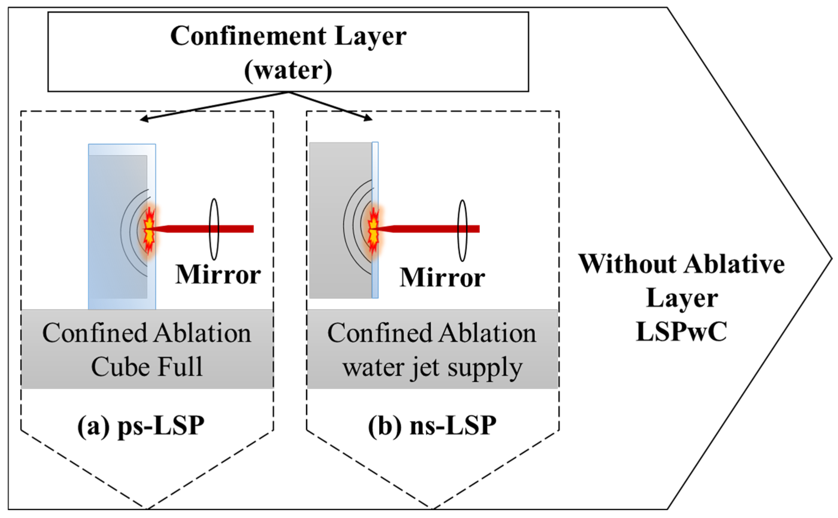
Figure 1. Configuration of the two distinct LSP treatment modalities with confined ablation: (a) Cube Full configuration, (b) water jet supply.
Materials 18 04649 g001
Figure 2. Experimental setup for ns-LSP surface treatment.
Materials 18 04649 g002
Figure 3. Experimental setup for ps-LSP surface treatment.
Materials 18 04649 g003
Figure 4. Comparation of laser spot size between ns-LSP and ps-LSP.
Materials 18 04649 g004
Figure 5. Graphical representation of the individual and combined treatments.
Materials 18 04649 g005
Figure 6. RS on 6061-T6 aluminium alloy target without LSP treatment.
Materials 18 04649 g006
Figure 7. Residual stresses with ns-LSP treatment.
Materials 18 04649 g007
Figure 8. Residual stresses with ps-LSP treatment.
Materials 18 04649 g008
Figure 9. Residual stresses with treatment combination, nsps-LSP.
Materials 18 04649 g009
Figure 10. Residual stresses with the psns-LSP treatment combination.
Materials 18 04649 g010
Figure 11. Depth microhardness profile at 500 gF load, comparison of untreated vs. ns-LSP, ps-LSP, nsps-LSP, psns-LSP.
Materials 18 04649 g011
Table 1. Chemical composition of 6061-T6 aluminium alloy used in this study [13].
Chemical Composition
ElementSiMgFeCuMnCrZnTiOthers
%0.4–0.80.8–1.20.70.15–0.400.8–1.20.04–0.350.250.150.15
Mechanical Properties
Heat TreatmentDensityPoisson CoefficientTensile StrengthYield StrengthElongation (%)Young ModuleVickers Hardness
T6g/cm3 M P a M P a 1/16
Thickness
1/2 Diameter G P a H V
2.70~0.33~310~276~12~1768.9107
Table 2. Laser beam parameter for the different ns-LSP and ps-LSP treatments.
Make and ModelPulse EnergyPulse WidthPulse
Frequency
Beam Diameter on SamplePower DensityPulse Density
mJsHz c m W / c m 2 P u l s e   c m 2
Quantel
Q-Smart
850 Nd-YAG
850 6 × 10 9 10   0.1 1.2 × 10 10 2500
Ekspla Atlantic
355-60
0.110 13 × 10 12 1 × 10 3 4.9 × 10 3 4.9 × 10 11 1 × 10 7
Table 3. Nomenclature and description of the different LSP treatments.
NomenclatureMeaningPulse Density
(Pulses/cm2)
Power Density
W / c m 2
Without-LSPTargets without LSP treatment
ns-LSPTargets treated with ns 2500 ns : 1.2 × 10 10
ps-LSPTargets treated with ps 1 × 1 0 7 p s : 4.9 × 10 11
nsps-LSPTargets treated with ns and post ps 2500
a n d
1 × 10 7
ns : 1.2 × 10 10
p s : 4.9 × 10 11
psns-LSPTargets treated with ps and post ns 1 × 10 7
a n d
2500
p s : 4.9 × 10 11
n s : 1.2 × 10 10
Table 4. Results of the highest compressive residual stress values and their depth for each treatment.
LSP TreatmentsCompressive Residual Stresses
Perpendicular (Sx)
(MPa)
Depth
(mm)
ns-LSP−3831.0
ps-LSP−1000.2
nsps-LSP−4280.85
psns-LSP−3560.95
Table 5. Roughness (Ra) value by contact profilometer.
TargetRoughness (Ra)
(μm)
without0.334±0.129
ns-LSP7.276±0.585
ps-LSP6.389±0.455
nsps-LSP7.167±0.539
psns-LSP12.109±0.504
Disclaimer/Publisher’s Note: The statements, opinions and data contained in all publications are solely those of the individual author(s) and contributor(s) and not of MDPI and/or the editor(s). MDPI and/or the editor(s) disclaim responsibility for any injury to people or property resulting from any ideas, methods, instructions or products referred to in the content.