
Features of the Defect Structure of LiNbO3:Mg:B Crystals of Different Composition and Genesis

 , , , ,

Highlights
- LiNbO3:Mg:B bulk crystals grown from charge obtained by two different methods are studied.
- Position of B is studied using a Coulomb interaction calculation.
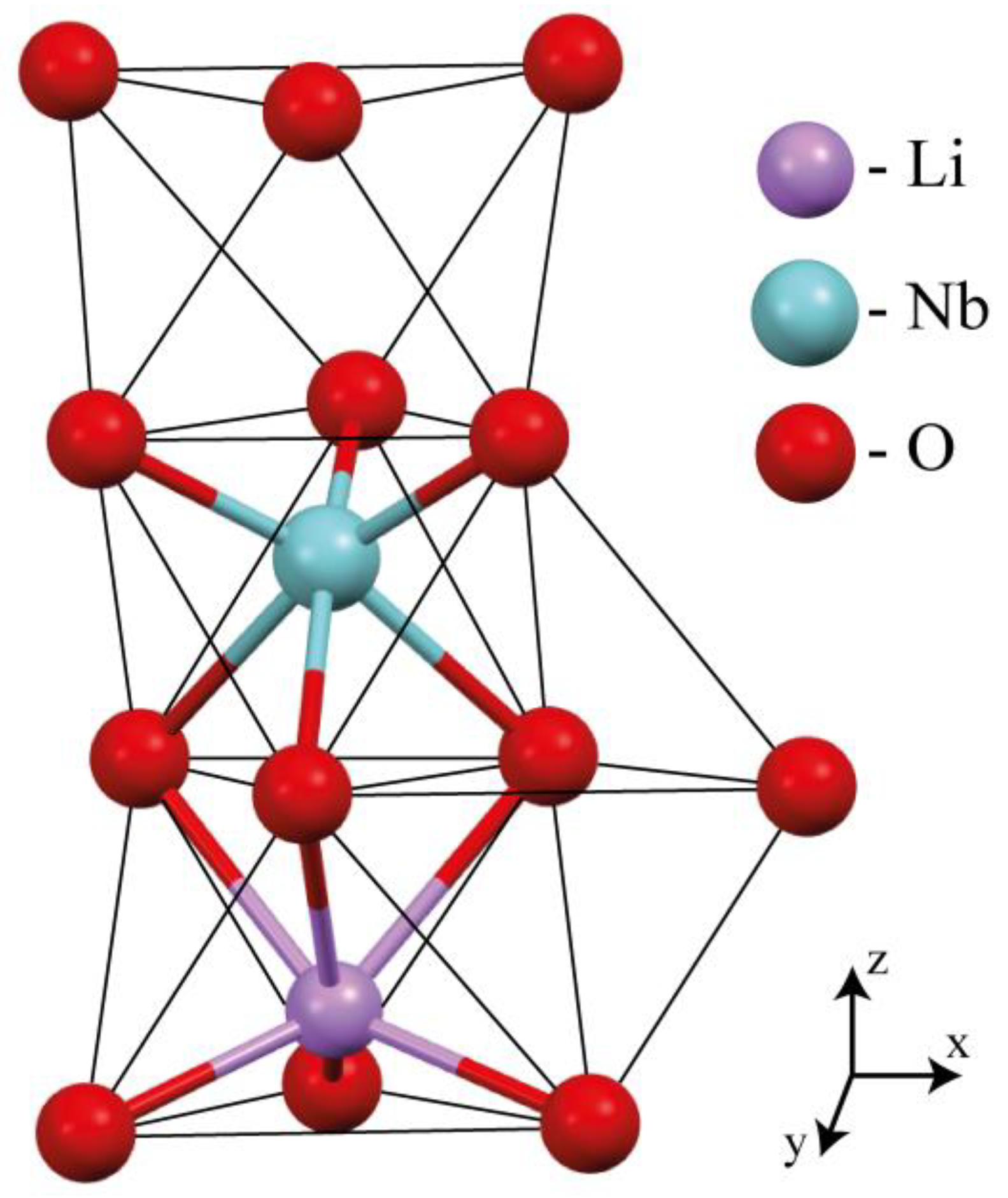
- B is placed in the tetrahedral voids of LN crystal structures.
- The most energetically favorable position is in the faces common with VNb5−.
- Direct doping is a better way to obtain perfect LiNbO3:Mg:B crystals.
Abstract
1. Introduction
2. Materials and Methods
- -
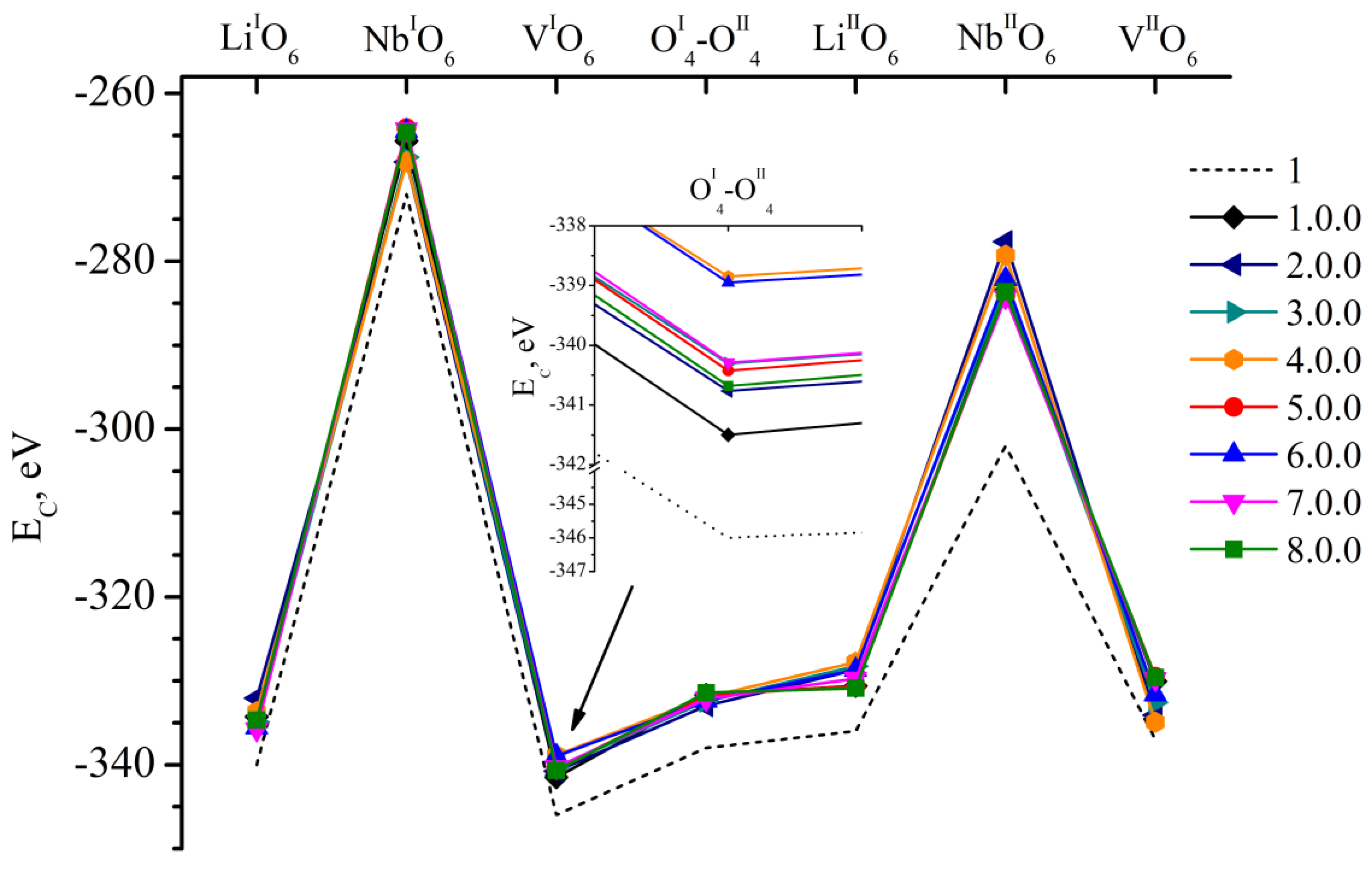
- 8 defect-free clusters (1.0.0–8.0.0);
- -
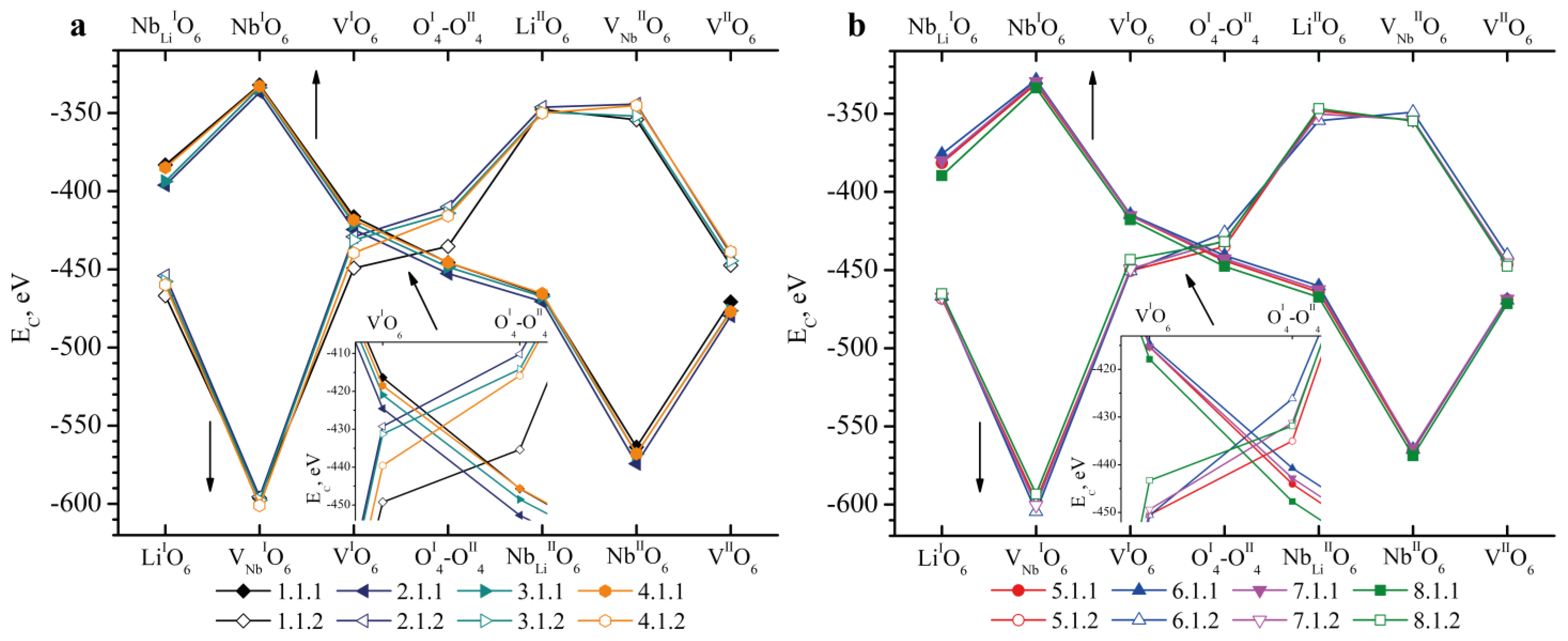
- 16 clusters containing an NbLi defect (1.1.1–8.1.1, 1.1.2–8.1.2);
- -
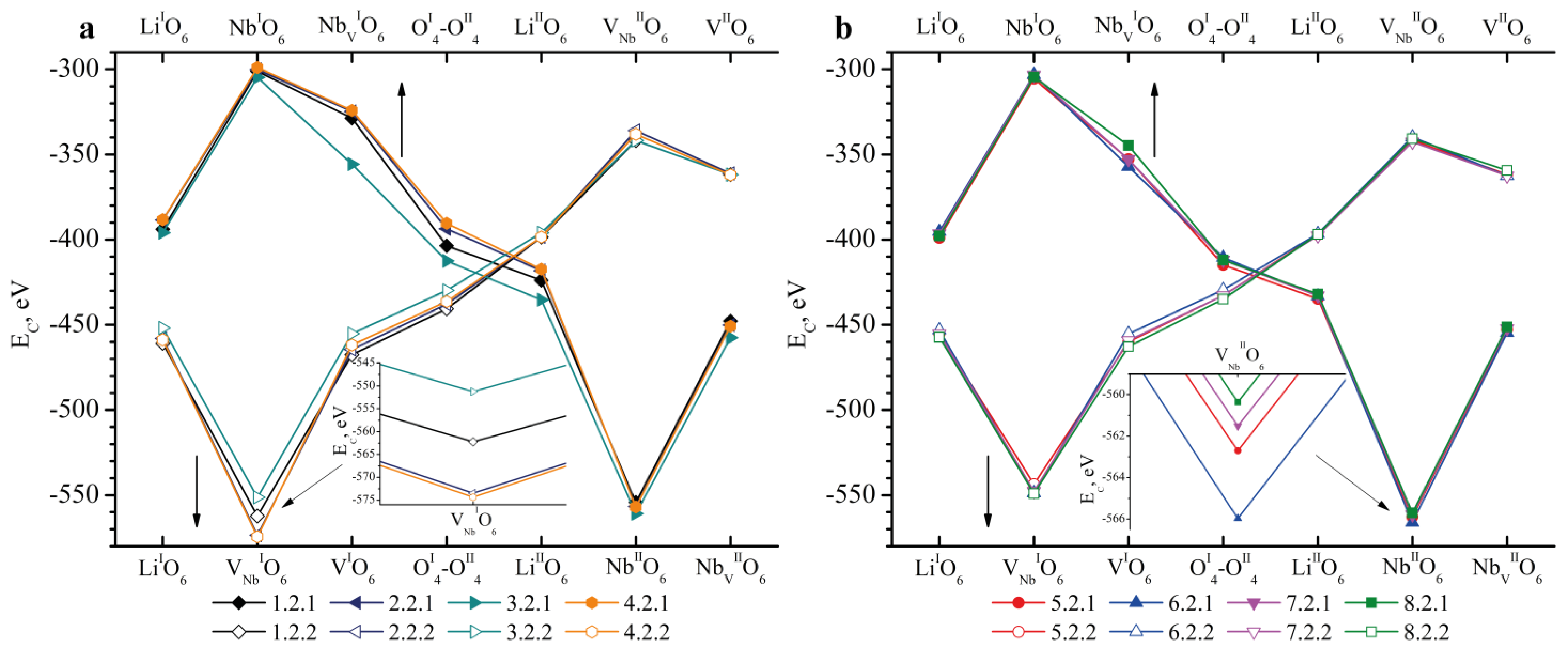
- 16 clusters containing an NbV defect (1.2.1–8.2.1, 1.2.2–8.2.2);
- -
- 16 clusters containing an MgLi defect (1.3.1–8.3.1, 1.3.2–8.3.2);
- -
- 8 clusters containing an MgV defect (1.4.1–4.4.2).
3. Results and Discussion
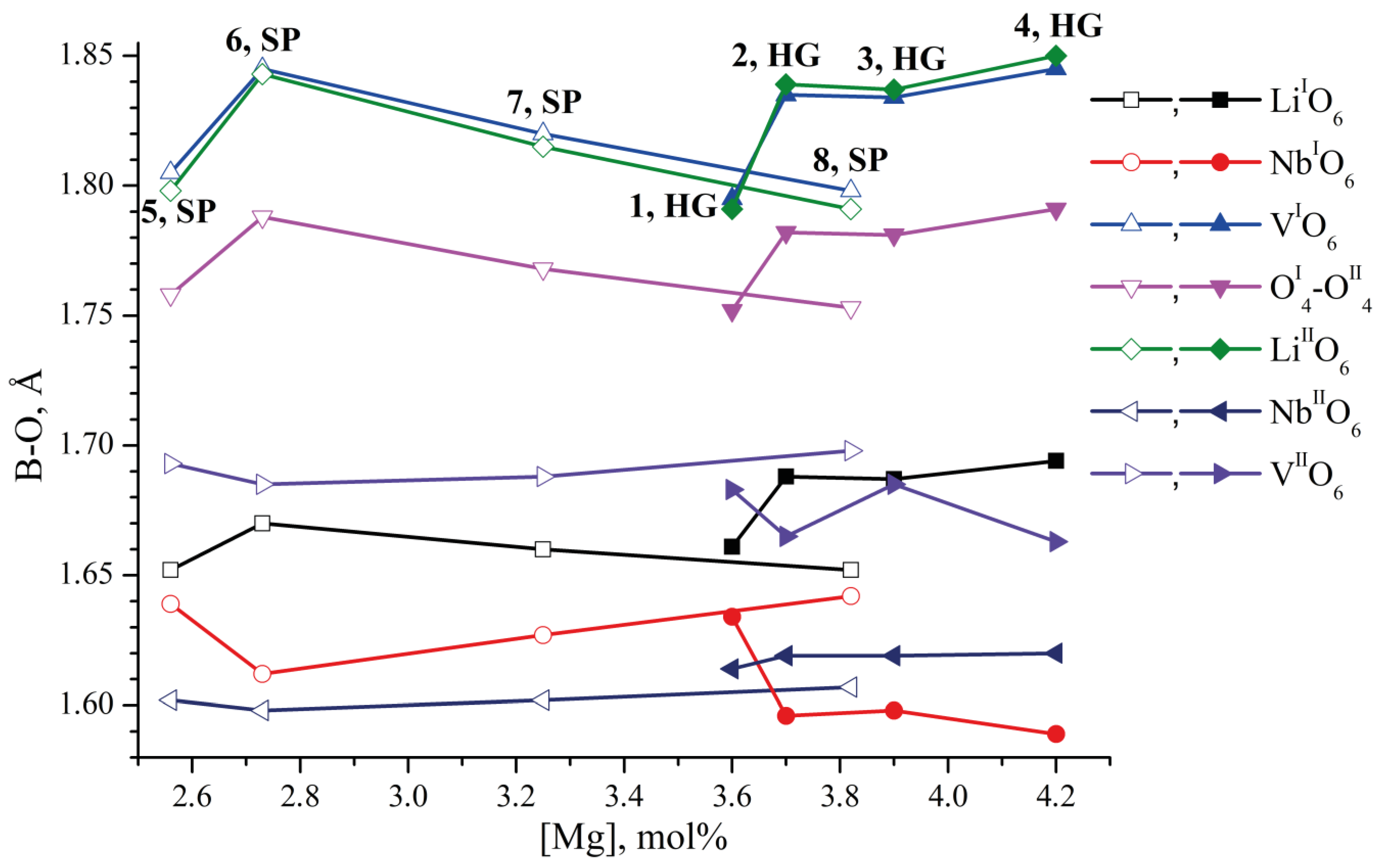
3.1. XRD Studies
3.2. Coulomb Energy Calculation Studies
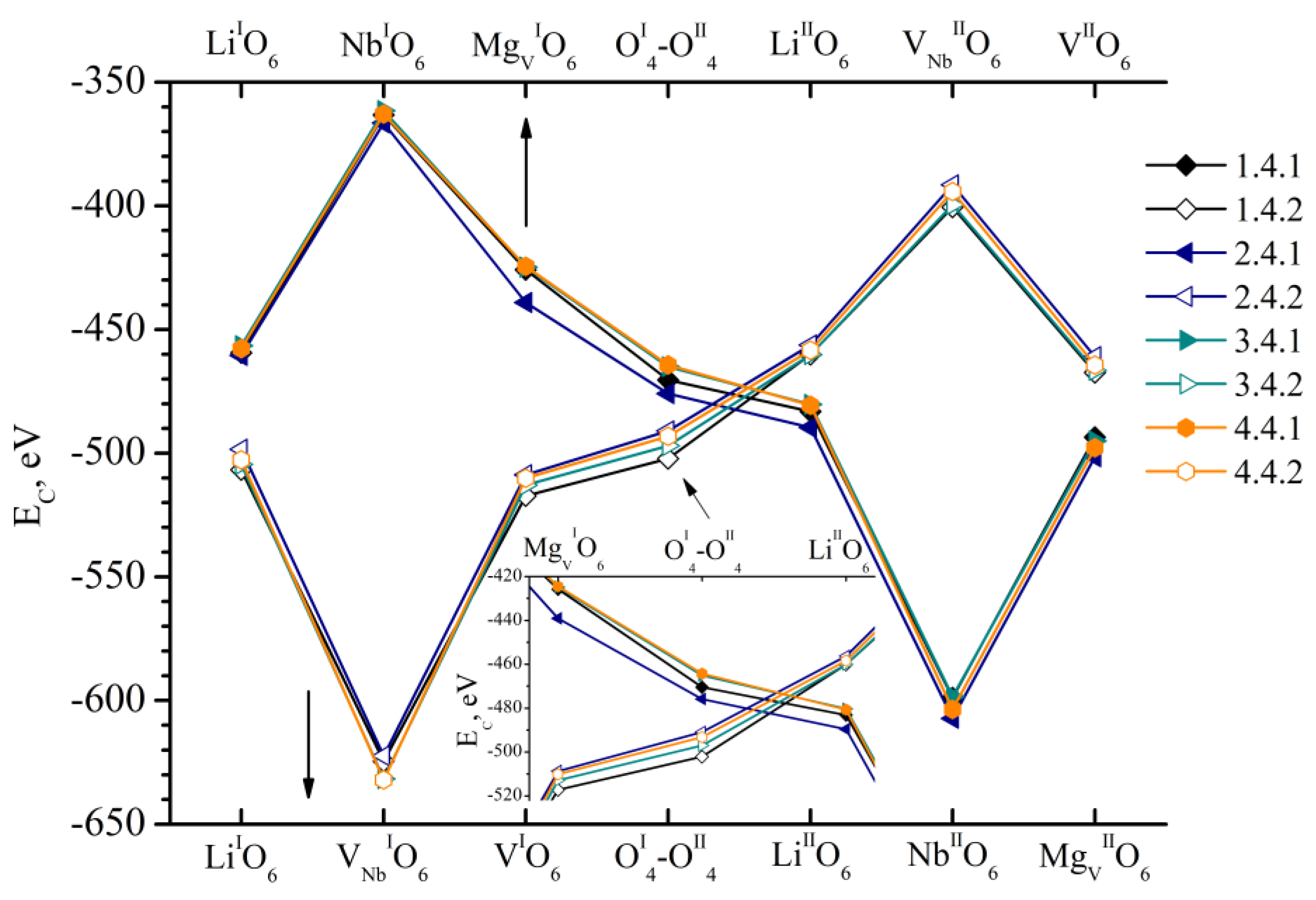
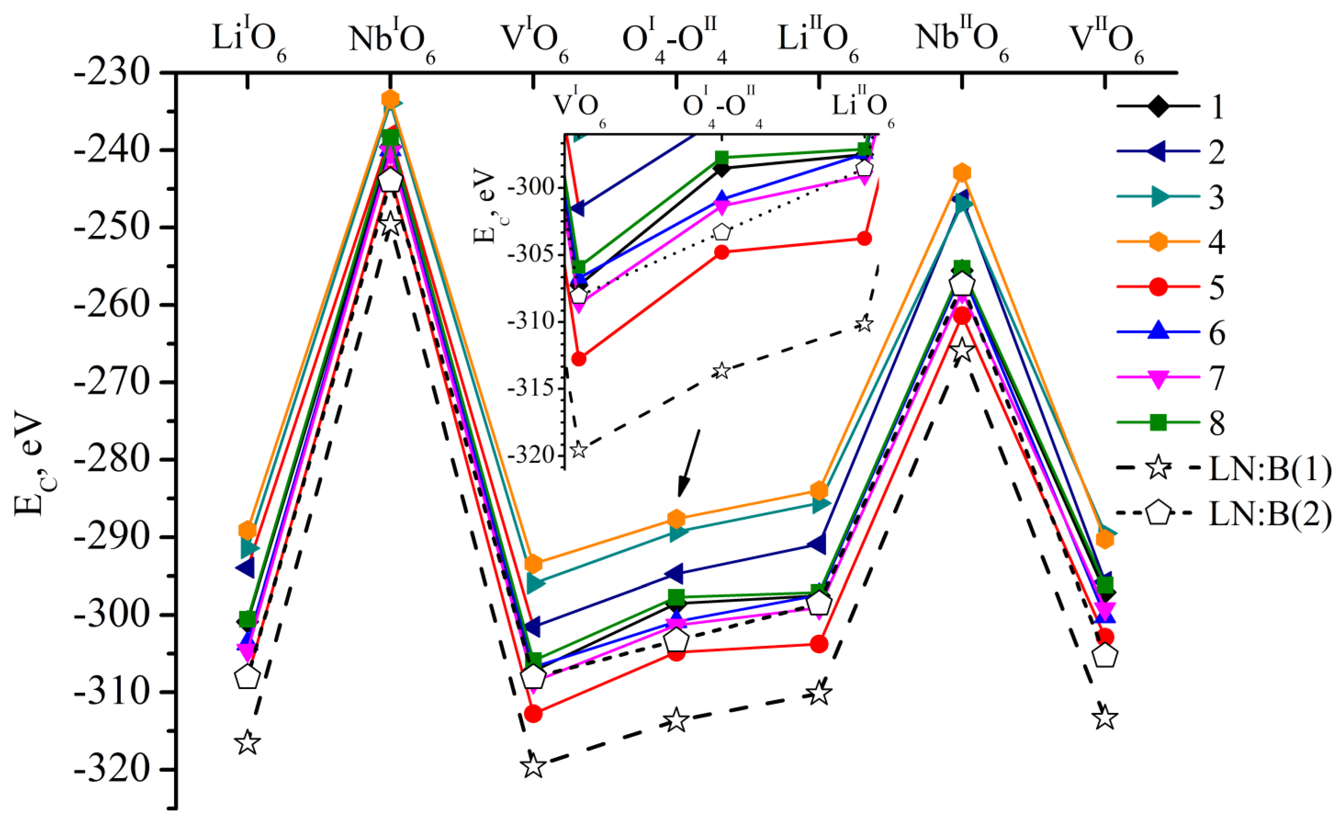
- We considered Clusters 1.1.1–8.3.2 and 1.4.1–4.4.2. They contain NbLi, NbV, MgLi and MgV defects compensated by VNb. In them, the most energetically favorable position for the boron cation and the system as a whole will be its localization in the oxygen plane adjacent to the vacant niobium octahedron. The exception is Clusters 1.2.1–8.2.2. They contain the NbV defect. For these clusters, the presence of a boron cation in the faces of vacant tetrahedral voids common with the vacant niobium octahedron from the second layer (VNbIIO6) will be more energetically favorable. The exception is Clusters 2.2.2 and 4.2.2, for which the minimum EC is still characteristic of the VNbIO6 position, Figure 5.
- The mutual arrangement of the structural units of the clusters (oxygen framework, main cations and structural defects) of real magnesium–boron co-doped LN crystals depends on several factors and affects the localization of boron cations in the structure. The factors are the doping technology, the type and concentration of dopants.
- Growing LN:Mg:B crystals from a higher concentration to a lower one reduces the overall defectiveness of the crystals.
- Despite the overall decrease in defectiveness, the LN:Mg:B(5-SP) crystal has the most stable structure. This is probably due to the absence of the MgV defect in it.
4. Conclusions
Author Contributions
Funding
Institutional Review Board Statement
Informed Consent Statement
Data Availability Statement
Conflicts of Interest
References
- Prokhorov, A.M.; Kuz’minov, Y.S. Physics and Chemistry of Crystalline Lithium Niobate; Adam Hilger: New York, NY, USA, 1990; 337p. [Google Scholar]
- Volk, T.; Wohlecke, M. Lithium niobate. In Defects, Photorefraction and Ferroelectric Switching; Springer: Berlin/Heidelberg, Germany, 2008; 250p. [Google Scholar]
- Fontana, M.D.; Bourson, P. Microstructure and defects probed by Raman spectroscopy in lithium niobate crystals and devices. J. Appl. Phys. Rev. 2015, 2, 040602. [Google Scholar] [CrossRef]
- Hong, N.; Cui, J.R.; Kim, H.J.; Shaffer, R.G.; Vinh, N.Q. New insights into refractive indices and birefringence of undoped and MgO-doped lithium niobate crystals at high temperatures. Opt. Mater. 2023, 145, 114365. [Google Scholar] [CrossRef]
- Schmidt, F.; Kozub, A.L.; Biktagirov, T.; Eigner, C.; Silberhorn, C.; Schindlmayr, A.; Schmidt, W.G.; Gerstmann, U. Free and defect-bound (bi)polarons in LiNbO3: Atomic structure and spectroscopic signatures from ab initio calculations. Phys. Rev. Res. 2020, 2, 043002. [Google Scholar] [CrossRef]
- Du, Y.; Pang, Z.; Zou, Y.; Zhu, B.; Liu, L.; Zhang, X.; Wang, C. Proton exchange-enhanced surface activated bonding for facile fabrication of monolithic lithium niobate microfluidic chips. Chem. Eng. J. 2024, 496, 154046. [Google Scholar] [CrossRef]
- Yu, S.; Fang, Z.; Zhou, Y.; Zhu, Y.; Huang, Q.; Ma, Y.; Liu, J.; Zhang, H.; Wang, M.; Cheng, Y. A high-power narrow-linewidth microlaser based on active-passive lithium niobate photonic integration. Opt. Laser Techn. 2024, 176, 110927. [Google Scholar] [CrossRef]
- Guo, Y.; Liu, L.; Liu, D.; Deng, S.; Zhi, Y. Absorption characteristic and nonvolatile holographic recording in LiNbO3:Cr:Cu crystals. Appl. Opt. 2005, 44, 7106–7111. [Google Scholar] [CrossRef]
- Sidorov, N.V.; Volk, T.R.; Mavrin, B.N.; Kalinnikov, V.T. Lithium Niobate: Defects, Photorefraction, Vibrational Spectrum, Polaritons; Nauka: Moscow, Russia, 2003; p. 255. (In Russian) [Google Scholar]
- Arizmendi, L. Photonic applications of lithium niobate crystals. Phys. Status Solidi 2004, 201, 253–283. [Google Scholar] [CrossRef]
- Gunter, P.; Huignard, J.-P. Photorefractive Materials and Their Applications; N.Y. Springer Science + Busines Media. LLC: New York, NY, USA, 2007; 647P. [Google Scholar] [CrossRef]
- Wang, Y.; Wang, R.; Yuan, J.; Wang, Y. Terahertz generation from Cu ion implantation into lithium niobate. J. Luminesc. 2014, 147, 242–244. [Google Scholar] [CrossRef]
- Blázquez-Castro, A.; García-Cabañes, A.; Carrascosa, M. Biological applications of ferroelectric materials. Appl. Phys. Rev. 2018, 5, 041101. [Google Scholar] [CrossRef]
- Wang, C.; Su, H.; Zhang, J.; Zhao, H. Surface metallization from ab initio theory and subwavelength coupling via surface plasmon polaritons in Cu-doped lithium niobate/tantalate owing to charge accumulation. Appl. Surf. Sci. 2021, 551, 149294. [Google Scholar] [CrossRef]
- Ma, X.; Xiong, Z.; Huo, D.; Wang, Y.; Su, H.; Wang, C.; Zhao, H. Long-ranged surface plasmon polaritons and their coupling with upconversion emissions in indium-tin-oxide-coated erbium and iron codoped LiNbO3. J. Opt. Soc. Am. B 2021, 38, 2984–2992. [Google Scholar] [CrossRef]
- Kukhtarev, N.V.; Kukhtareva, T.V.; Stargell, G.; Wang, J.C. Pyroelectric and photogalvanic crystal accelerators. J. Appl. Phys. 2009, 106, 014111. [Google Scholar] [CrossRef]
- Carrascosa, M.; García-Cabañes, A.; Jubera, M.; Ramiro, J.B.; Agulló-López, F. LiNbO3: A photovoltaic substrate for massive parallel manipulation and patterning of nano-objects. Appl. Phys. Rev. 2015, 2, 040605. [Google Scholar] [CrossRef]
- Mambetova, K.M.; Shandarov, S.M.; Tatyannikov, A.I.; Smirnov, S.V. Aggregation of dielectric nanoparticles on the x-cut of LiNbO3:Cu crystal by electric fields of photorefractive holograms. Russ. Phys. J. 2019, 62, 658–663. [Google Scholar] [CrossRef]
- Puerto, A.; Méndez, A.; Arizmendi, L.; García-Cabañes, A.; Carrascosa, M. Optoelectronic manipulation, trapping, splitting, and merging of water droplets and aqueous biodroplets based on the bulk photovoltaic effect. Phys. Rev. Appl. 2020, 14, 024046. [Google Scholar] [CrossRef]
- Zaltron, A.; Ferraro, D.; Meggiolaro, A.; Cremaschini, S.; Carneri, M.; Chiarello, E.; Sartori, P.; Pierno, M.; Sada, C.; Mistura, G. Optofluidic platform for the manipulation of water droplets on engineered LiNbO3 surfaces. Adv. Mater. Interf. 2022, 9, 2200345. [Google Scholar] [CrossRef]
- Zhang, X.; Mugisha, E.R.; Mi, Y.; Liu, X.; Wang, M.; Gao, Z.; Gao, K.; Shi, L.; Chen, H.; Yan, W. Photovoltaic cycling to-and-fro actuation of a water-microdroplet for automatic repeatable solute acquisition on oil-infused hydrophobic LN:Fe surface. ACS Photonics 2021, 8, 639–647. [Google Scholar] [CrossRef]
- Azuma, Y.; Uda, S. Electric current induced compositional variation in LiNbO3 fiber crystal grown by a micro-pulling down method. J. Cryst. Growth 2007, 306, 217–224. [Google Scholar] [CrossRef]
- Palatnikov, M.N.; Shcherbina, O.B.; Sandler, V.A.; Sidorov, N.V. Study of a stoichiometric lithium tantalate crystal obtained by VTE (Vapor transport equilibration) processing. Perspect. Mater. 2011, 2, 659–664. (In Russian) [Google Scholar]
- Lengyel, K.; Peter, A.; Kovacs, L.; Corradi, G.; Palfalvi, L.; Hebling, J.; Unferdorben, M.; Dravecz, G.; Hajdara, I.; Szaller, Z.; et al. Growth, defect structure, and THz application of stoichiometric lithium niobate. Appl. Phys. Rev. 2015, 2, 040601. [Google Scholar] [CrossRef]
- Polgar, K.; Peter, A.; Kovacs, L.; Corradi, G.; Szaller, Z. Growth of stoichiometric LiNbO3 single crystals by top seeded solution growth method. J. Cryst. Growth 1997, 177, 211–216. [Google Scholar] [CrossRef]
- Titov, R.; Kadetova, A.; Tokko, O.; Sidorov, N.; Palatnikov, M.; Teplyakova, N.; Masloboeva, S.; Biryukova, I.; Efremov, I.; Manukovskaya, D. Influence of Doping Technology on the Stoichiometry and Features of the Localization of B3+ Cations in LiNbO3:B Single Crystals. Crystals 2023, 13, 1245. [Google Scholar] [CrossRef]
- Palatnikov, M.N.; Sidorov, N.V.; Kadetova, A.V.; Titov, R.A.; Biryukova, I.V.; Makarova, O.V.; Manukovskaya, D.V.; Teplyakova, N.A.; Efremov, I.N. Growing, structure and optical properties of LiNbO3:B crystals, a material for laser radiation transformation. Materials 2023, 16, 732. [Google Scholar] [CrossRef] [PubMed]
- Shur, V.Y.; Akhmatkhanov, A.R.; Baturin, I.S. Micro- and nano-domain engineering in lithium niobate. Appl. Phys. Rev. 2015, 2, 040604. [Google Scholar] [CrossRef]
- Kemlin, V.; Jegouso, D.; Debray, J.; Boursier, E.; Segonds, P.; Boulanger, B.; Ishizuki, H.; Taira, T.; Mennerat, G.; Melkonian, J.-M.; et al. Dual-wavelength source from 5% MgO:PPLN cylinders for the characterization of nonlinear infrared crystals. Opt. Express 2013, 21, 28886–28891. [Google Scholar] [CrossRef]
- Murray, R.T.; Runcorn, T.H.; Guha, S.; Taylor, J.R. High average power parametric wavelength conversion at 3.31–3.48 μm in MgO:PPLN. Opt. Express 2017, 25, 6421–6430. [Google Scholar] [CrossRef]
- Sidorov, N.V.; Teplyakova, N.A.; Palatnikov, M.N. Influence of the method of doping on uniformity and optical properties of LiNbO3:Mg crystals. Phys. Chem. Asp. Study Clust. Nanostr. Nanomater. 2021, 13, 383–391. (In Russian) [Google Scholar]
- Wang, F.; Sun, D.; Liu, Q.; Song, Y.; Zhang, F.; Zhou, W.; Sang, Y.; Wang, D.; Liu, H. Growth of large size near-stoichiometric lithium niobate single crystals with low coercive field for manufacturing high quality periodically poled lithium niobate. Opt. Mater. 2022, 125, 112058. [Google Scholar] [CrossRef]
- Iyi, N.; Kitamura, K.; Izumi, F.; Yamamoto, J.K.; Hayashi, T.; Asano, H.; Kimura, S. Comparative study of defect structures in lithium niobate with different compositions. J. Solid State Chem. 1992, 101, 340–352. [Google Scholar] [CrossRef]
- Blumel, J.; Born, E.; Metzger, T. Solid state NMR study supporting the lithium vacancy defect model in congruent lithium niobate. J. Phys. Chem. Solids 1994, 55, 589–593. [Google Scholar] [CrossRef]
- Sánchez-Dena, O.; Villalobos-Mendoza, S.D.; Farías, R.; Fierro-Ruiz, C.D. Lithium Niobate Single Crystals and Powders Reviewed—Part II. Crystals 2020, 10, 990. [Google Scholar] [CrossRef]
- Kovács, L.; Kocsor, L.; Tichy-Rács, É.; Lengyel, K.; Béncs, L.; Corradi, G. Hydroxyl ion probing transition metal dopants occupying Nb sites in stoichiometric LiNbO3. Opt. Mater. Express 2019, 9, 4506–4516. [Google Scholar] [CrossRef]
- Kong, Y.; Bo, F.; Wang, W.; Zheng, D.; Liu, H.; Zhang, G.; Rupp, R.; Xu, J. Recent Progress in Lithium Niobate: Optical Damage, Defect Simulation, and On-Chip Devices. Adv. Mater. 2019, 32, 1806452. [Google Scholar] [CrossRef] [PubMed]
- Sulyanov, S.; Volk, T. Lattice Parameter of Optical Damage Resistant In-Doped LiNbO3 Crystals. Crystals 2018, 8, 210. [Google Scholar] [CrossRef]
- Palatnikov, M.; Makarova, O.; Kadetova, A.; Sidorov, N.; Teplyakova, N.; Biryukova, I.; Tokko, O. Structure, Optical Properties and Physicochemical Features of LiNbO3:Mg,B Crystals Grown in a Single Technological Cycle: An Optical Material for Converting Laser Radiation. Materials 2023, 16, 4541. [Google Scholar] [CrossRef]
- Kadetova, A.V.; Tokko, O.V.; Prusskii, A.I.; Smirnov, M.V.; Palatnikov, M.N.; Biryukova, I.V. The role of doping technology in the formation of nonlinear optical properties of LiNbO3:Mg:B crystals. Opt. Mater. 2024, 156, 115921. [Google Scholar] [CrossRef]
- Sidorov, N.V.; Teplyakova, N.A.; Makarova, O.V.; Palatnikov, M.N.; Titov, R.A.; Manukovskaya, D.V.; Birukova, I.V. Boron influence on defect structure and properties of lithium niobate crystals. Crystals 2021, 11, 458. [Google Scholar] [CrossRef]
- Vafek, O.; Kang, J. Renormalization Group Study of Hidden Symmetry in Twisted Bilayer Graphene with Coulomb Interactions. Phys. Rev. Lett. 2020, 125, 257602. [Google Scholar] [CrossRef]
- Cea, T.; Guinea, F. Coulomb interaction, phonons, and superconductivity in twisted bilayer graphene. Appl. Phys. Sci. 2021, 118, e2107874118. [Google Scholar] [CrossRef]
- Shi, J.; Zhao, N.; Yan, D.; Song, J.; Fu, W.; Li, Z. Design of a mechanically strong and highly stretchable thermoplastic silicone elastomer based on coulombic interactions. J. Mater. Chem. A 2020, 8, 5943–5951. [Google Scholar] [CrossRef]
- Chiou, D.-S.; Yu, H.J.; Hung, T.-H.; Lyu, Q.; Chang, C.-K.; Lee, J.S.; Lin, L.-C.; Kang, D.-Y. Highly CO2 Selective Metal–Organic Framework Membranes with Favorable Coulombic Effect. Adv. Funct. Mater. 2021, 31, 2006924. [Google Scholar] [CrossRef]
- Erkensten, D.; Brem, S.; Malic, E. Exciton-exciton interaction in transition metal dichalcogenide monolayers and van der Waals heterostructures. Phys. Rev. B 2021, 103, 045426. [Google Scholar] [CrossRef]
- Rømer, A.T.; Hirschfeld, P.J.; Andersen, B.M. Superconducting state of Sr2RuO4 in the presence of longer-range Coulomb interactions. Phys. Rev. B 2021, 104, 064507. [Google Scholar] [CrossRef]
- Miao, S.; Wang, T.; Huang, X.; Chen, D.; Lian, Z.; Wang, C.; Blei, M.; Taniguchi, T.; Watanabe, K.; Tongay, S.; et al. Strong interaction between interlayer excitons and correlated electrons in WSe2/WS2 moiré superlattice. Nat. Commun. 2021, 12, 3608. [Google Scholar] [CrossRef] [PubMed]
- Kiczynski, M.; Gorman, S.K.; Geng, H.; Donnelly, M.B.; Chung, Y.; He, Y.; Keizer, J.G.; Simmons, M.Y. Engineering topological states in atom-based semiconductor quantum dots. Nature 2022, 606, 694–699. [Google Scholar] [CrossRef] [PubMed]
- Li, Q.; Ning, D.; Wong, D.; An, K.; Tang, Y.; Zhou, D.; Schuck, G.; Chen, Z.; Zhang, N.; Liu, X. Improving the oxygen redox reversibility of Li-rich battery cathode materials via Coulombic repulsive interactions strategy. Nat. Commun. 2022, 13, 112. [Google Scholar] [CrossRef] [PubMed]
- Huang, J.; Wang, Y.; Wang, Y.; Wei, S.; Huang, Q.; Bai, S.; Wang, F.; Liu, Y.; Li, Z.; Chen, G.; et al. Altered S–S Coulomb Interactions in Polysulfides Associated with VS2/S Nanocomposite Electrodes for Na–S Batteries. ACS Appl. Nano Mater. 2024, 7, 7674–7683. [Google Scholar] [CrossRef]
- Donnerberg, H.J.; Tomlinson, S.M.; Catlows, C.R.A. Defects in LiNbO3. II. Computer simulation. J. Phys. Chem. Solids 1991, 52, 201–210. [Google Scholar] [CrossRef]
- Messerschmidt, S.; Krampf, A.; Vittadello, L.; Imlau, M.; Nörenberg, T.; Eng, L.M.; Emin, D. Small-polaron hopping and low-temperature (45–225 K) photo-induced transient absorption in magnesium-doped lithium niobate. Crystals 2020, 10, 809. [Google Scholar] [CrossRef]
- Kalimullah, N.M.M.; Shukla, K.; Shelke, A.; Habib, A. Stiffness tensor estimation of anisotropic crystal using point contact method and unscented Kalman filter. Ultrasonics 2023, 131, 106939. [Google Scholar] [CrossRef]
- Masloboeva, S.M.; Efremov, I.N.; Biryukova, I.V.; Palatnikov, M.N. Preparation and Characterization of Lithium Niobate Single Crystals Activated with Magnesium and Boron. Inorg. Mater. 2021, 57, 1271–1278. [Google Scholar] [CrossRef]
- Biryukova, I.V.; Efremov, I.N.; Masloboeva, S.M.; Palatnikov, M.N. Effect of the Doped Growth Charge Preparation Process on the Growth Conditions and Properties of LiNbO3:B:Mg Single Crystals. Inorg. Mater. 2022, 58, 948–955. [Google Scholar] [CrossRef]
- Lerner, P.; Legras, C.; Dumas, J.P. Stoechiométrie des monocristaux de métaniobate de lithium. J. Cryst. Growth 1968, 3, 231–235. [Google Scholar] [CrossRef]
- Peterson, G.E.; Carnevale, A. 93Nb NMR Linewidths in Nonstoichiometric Lithium Niobate. J. Chem. Phys. 1972, 6, 4848–4851. [Google Scholar] [CrossRef]
- Zotov, N.; Boysen, H.; Frey, F.; Metzger, T.; Born, E. Cation substitution models of congruent LiNbO3 investigated by X-ray and neutron powder diffraction. J. Phys. Chem. Solids 1994, 55, 145–152. [Google Scholar] [CrossRef]
- Palatnikov, M.N.; Kadetova, A.V.; Aleshina, L.A.; Sidorova, O.V.; Sidorov, N.V.; Biryukova, I.V.; Makarova, O.V. Growth, structure, physical and chemical characteristics in a series of LiNbO3:Er crystals of different composition grown in one technological cycle. Opt. Laser Technol. 2022, 147, 107671. [Google Scholar] [CrossRef]
- Palatnikov, M.N.; Sidorov, N.V.; Kadetova, A.V.; Teplyakova, N.A.; Makarova, O.V.; Manukovskaya, D.V. Concentration threshold in optically nonlinear LiNbO3:Tb crystals. Opt. Laser Technol. 2021, 137, 106821. [Google Scholar] [CrossRef]
- Shannon, R.D. Revised Effective Ionic Radii and Systematic Studies of Interatomic Distances in Halides and Chalcogenides. Acta Cryst. 1976, 32, 751–767. [Google Scholar] [CrossRef]
- Palatnikov, M.N.; Birukova, I.V.; Masloboeva, S.M.; Makarova, O.V.; Manukovskaya, D.V.; Sidorov, N.V. The search of homogeneity of LiNbO3 crystals grown of charge with different genesis. J. Cryst. Growth 2014, 386, 113–118. [Google Scholar] [CrossRef]


| Doping Technology | HG | SP | ||||||
|---|---|---|---|---|---|---|---|---|
| Sample number | 1 | 2 | 3 | 4 | 5 | 6 | 7 | 8 |
| [Mg] in crystal, mol% | 3.6 | 3.7 | 3.9 | 4.2 | 2.57 | 2.73 | 3.25 | 3.82 |
| [B] in crystal cone, 10−4 wt% | 0.59 | 1.0 | 1.7 | 9.0 | 0.42 | 0.76 | 1.13 | 2.07 |
| A | B | C |
|---|---|---|
| 1 | 0 No defects 1 NbLi 2 NbV 3 MgLi 4 MgV | 0 No defects 1 Defect in layer I 2 Defect in layer II |
| 2 | ||
| 3 | ||
| 4 | ||
| 5 | ||
| 6 | ||
| 7 | ||
| 8 |
| G | x/a | y/b | z/c | G | x/a | y/b | z/c | ||
|---|---|---|---|---|---|---|---|---|---|
| LN:Mg:B(2-HG): C(Mg) = 3.7 mol% Rwp(%) = 6.76, Rp(%) = 9.62 | LN:Mg:B(3-HG): C(Mg) = 3.9 mol % Rwp(%) = 6.59 Rp(%) = 8.44 | ||||||||
| Nb | 0.956 | 0 | 0 | 0 | Nb | 0.925 | 0 | 0 | 0 |
| O | 1.0 | 0.0551 | 0.3249 | 0.0686 | O | 1.0 | 0.0547 | 0.3255 | 0.0634 |
| Li | 0.958 | 0 | 0 | 0.2950 | Li | 0.969 | 0 | 0 | 0.2783 |
| NbLi | 0.014 | 0 | 0 | 0.2732 | NbLi | 0.013 | 0 | 0 | 0.2670 |
| NbV | 0.017 | 0 | 0 | 0.1550 | NbV | 0.018 | 0 | 0 | 0.1109 |
| MgLi | 0.017 | 0 | 0 | 0.2690 | MgLi | 0.018 | 0 | 0 | 0.2900 |
| MgV | 0.025 | 0 | 0 | 0.1212 | MgV | 0.026 | 0 | 0 | 0.1470 |
| LN:Mg:B(5-SP): C(Mg) = 2.57 mol%; Rwp(%) = 6.78, Rp(%) = 6.39 | LN:Mg:B(6-SP): C(Mg) = 2.73 mol % Rwp(%) = 8.12, Rp(%) = 6.36 | ||||||||
| Nb | 0.957 | 0 | 0 | 0 | Nb | 0.955 | 0 | 0 | 0 |
| O | 1.0 | 0.0544 | 0.3473 | 0.0637 | O | 1.00 | 0.0642 | 0.3387 | 0.0643 |
| Li | 0.963 | 0 | 0 | 0.2807 | Li | 0.957 | 0 | 0 | 0.2821 |
| NbLi | 0.015 | 0 | 0 | 0.2803 | NbLi | 0.012 | 0 | 0 | 0.2900 |
| NbV | 0.009 | 0 | 0 | 0.1100 | Nbv | 0.017 | 0 | 0 | 0.1100 |
| MgLi | 0.027 | 0 | 0 | 0.2756 | MgLi | 0.031 | 0 | 0 | 0.2877 |
Disclaimer/Publisher’s Note: The statements, opinions and data contained in all publications are solely those of the individual author(s) and contributor(s) and not of MDPI and/or the editor(s). MDPI and/or the editor(s) disclaim responsibility for any injury to people or property resulting from any ideas, methods, instructions or products referred to in the content. |
© 2025 by the authors. Licensee MDPI, Basel, Switzerland. This article is an open access article distributed under the terms and conditions of the Creative Commons Attribution (CC BY) license (https://creativecommons.org/licenses/by/4.0/).
Share and Cite
Titov, R.A.; Kadetova, A.V.; Manukovskaya, D.V.; Smirnov, M.V.; Tokko, O.V.; Sidorov, N.V.; Biryukova, I.V.; Masloboeva, S.M.; Palatnikov, M.N. Features of the Defect Structure of LiNbO3:Mg:B Crystals of Different Composition and Genesis. Materials 2025, 18, 436. https://doi.org/10.3390/ma18020436
Titov RA, Kadetova AV, Manukovskaya DV, Smirnov MV, Tokko OV, Sidorov NV, Biryukova IV, Masloboeva SM, Palatnikov MN. Features of the Defect Structure of LiNbO3:Mg:B Crystals of Different Composition and Genesis. Materials. 2025; 18(2):436. https://doi.org/10.3390/ma18020436
Chicago/Turabian StyleTitov, Roman A., Alexandra V. Kadetova, Diana V. Manukovskaya, Maxim V. Smirnov, Olga V. Tokko, Nikolay V. Sidorov, Irina V. Biryukova, Sofja M. Masloboeva, and Mikhail N. Palatnikov. 2025. "Features of the Defect Structure of LiNbO3:Mg:B Crystals of Different Composition and Genesis" Materials 18, no. 2: 436. https://doi.org/10.3390/ma18020436
APA StyleTitov, R. A., Kadetova, A. V., Manukovskaya, D. V., Smirnov, M. V., Tokko, O. V., Sidorov, N. V., Biryukova, I. V., Masloboeva, S. M., & Palatnikov, M. N. (2025). Features of the Defect Structure of LiNbO3:Mg:B Crystals of Different Composition and Genesis. Materials, 18(2), 436. https://doi.org/10.3390/ma18020436