

Experimental Investigation of Failure Behaviors of CFRP–Al Lap Joints with Various Configurations Under High- and Low-Temperature Conditions

 ,
,
Abstract
1. Introduction
2. Specimen Preparation and Experimental Testing
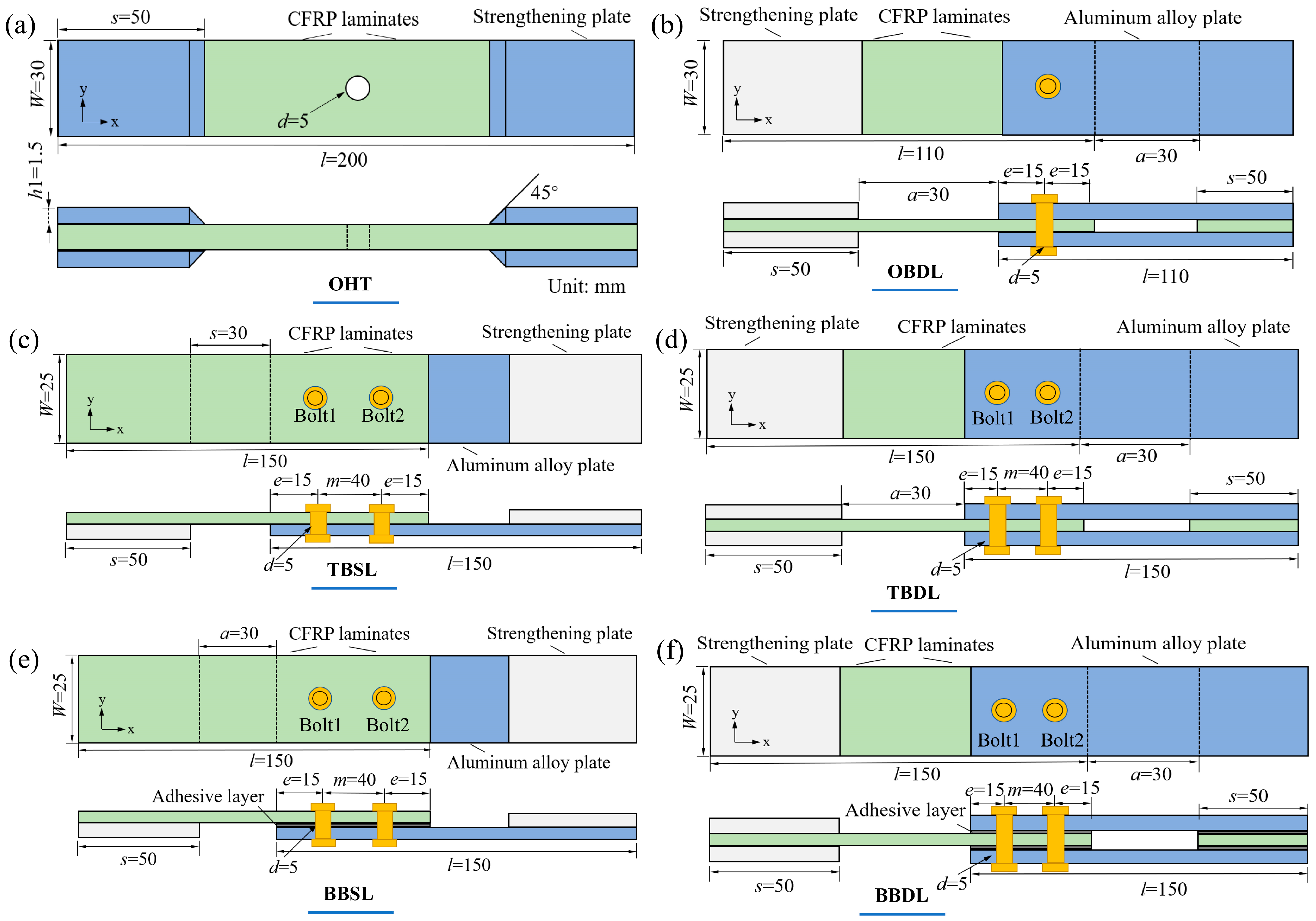
2.1. Specimen Preparation
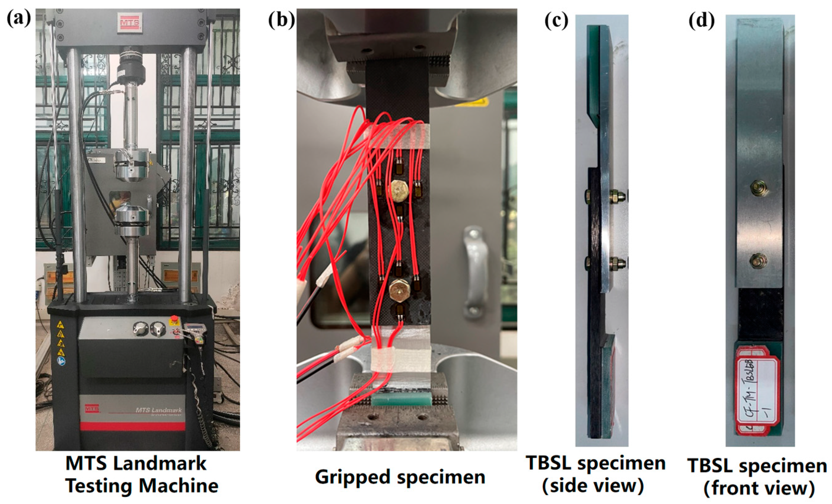
2.2. Experimental Testing
3. Experimental Results
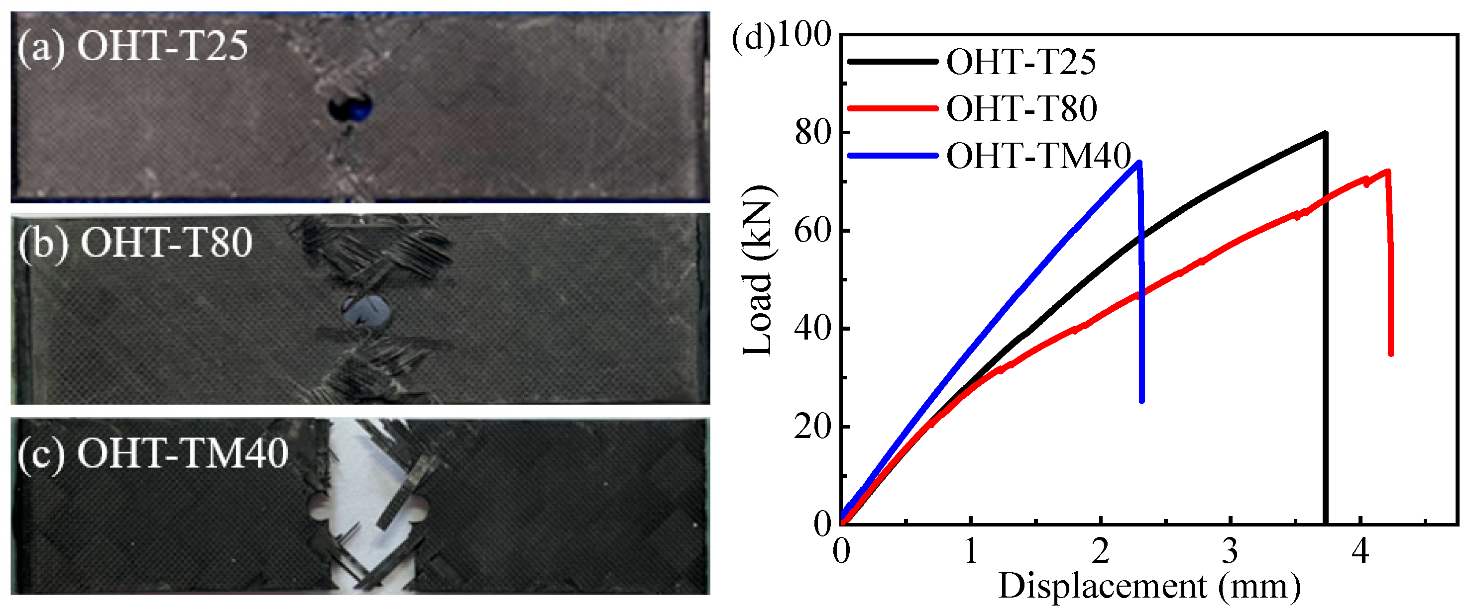
3.1. Tensile Failure Results of Open-Hole Laminates
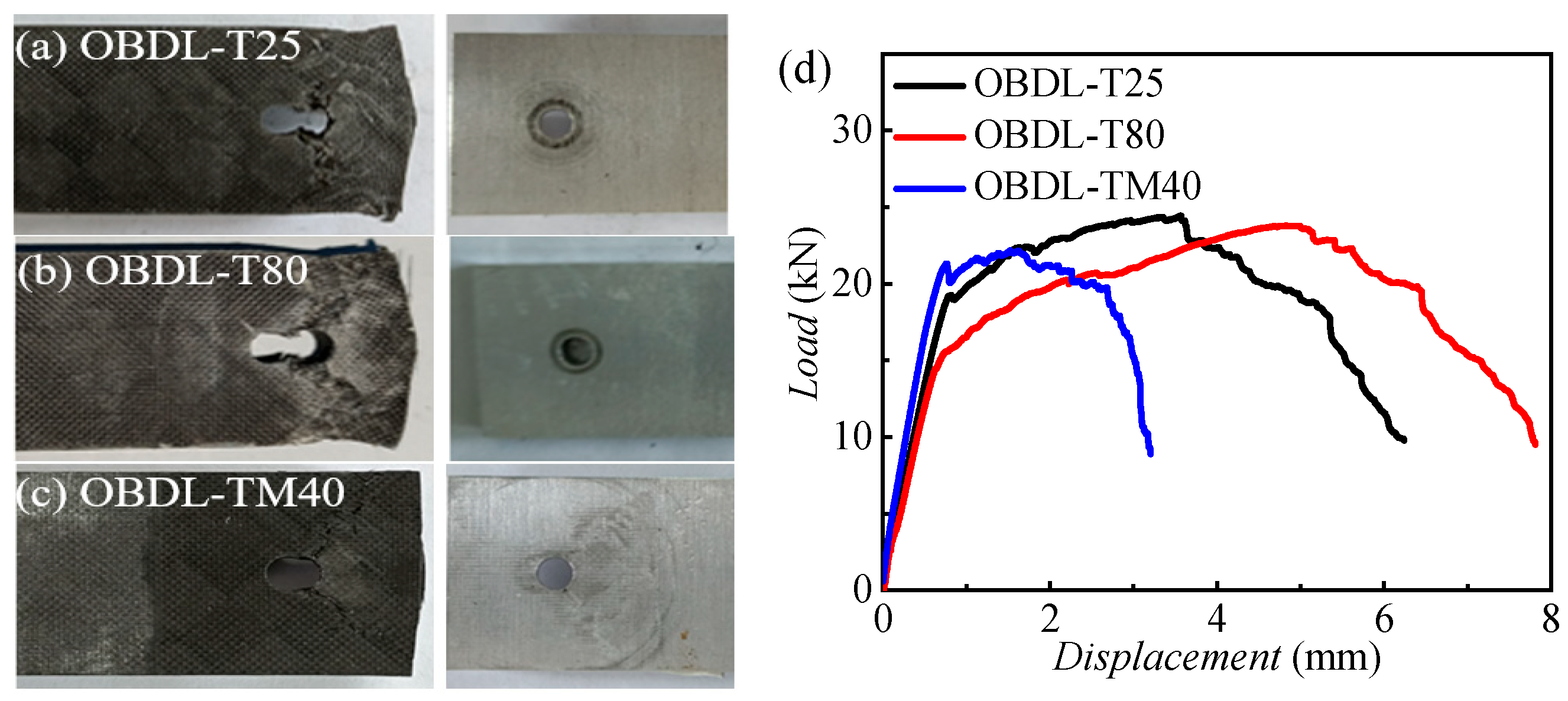
3.2. Tensile Failure Results of OBDL Specimens
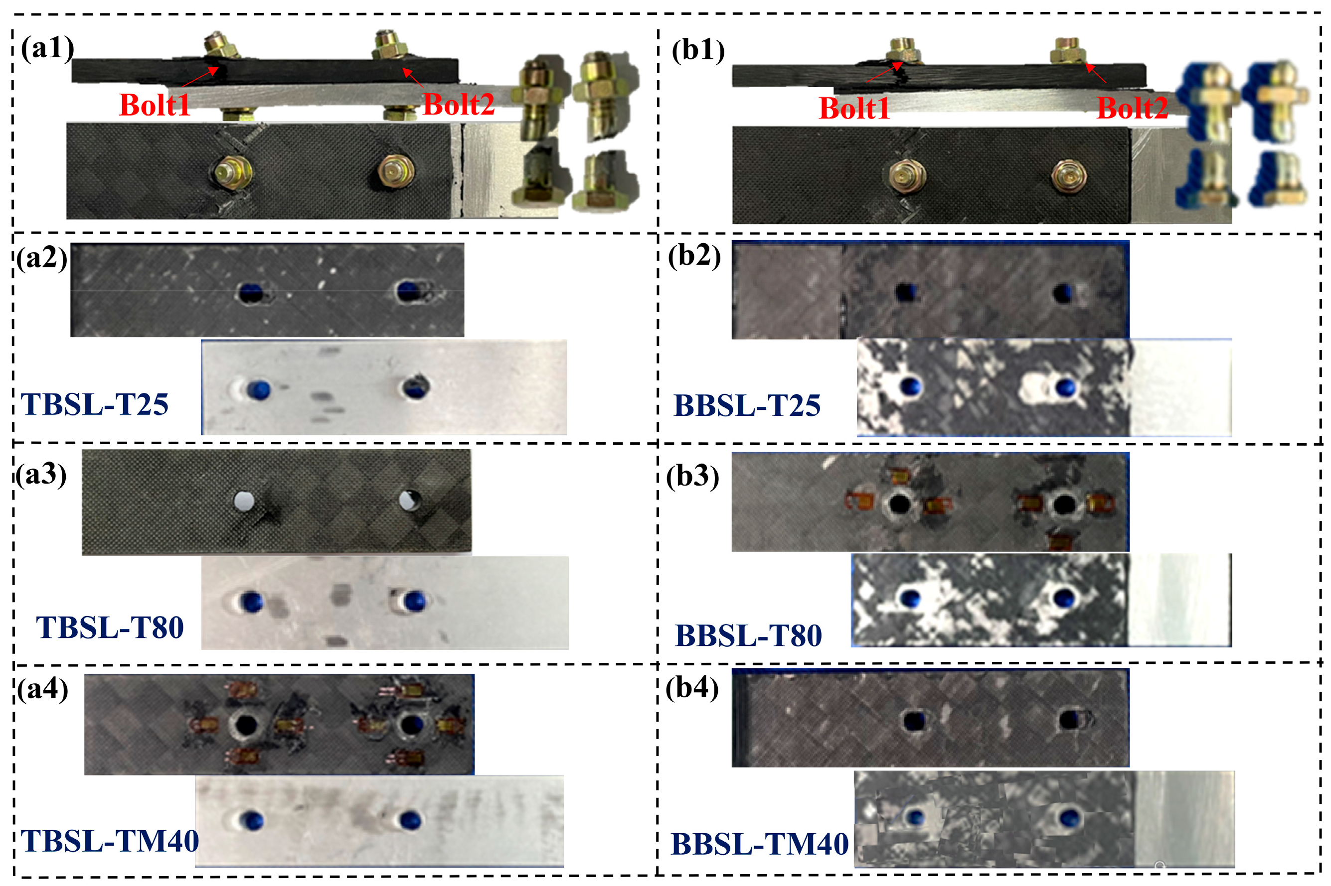
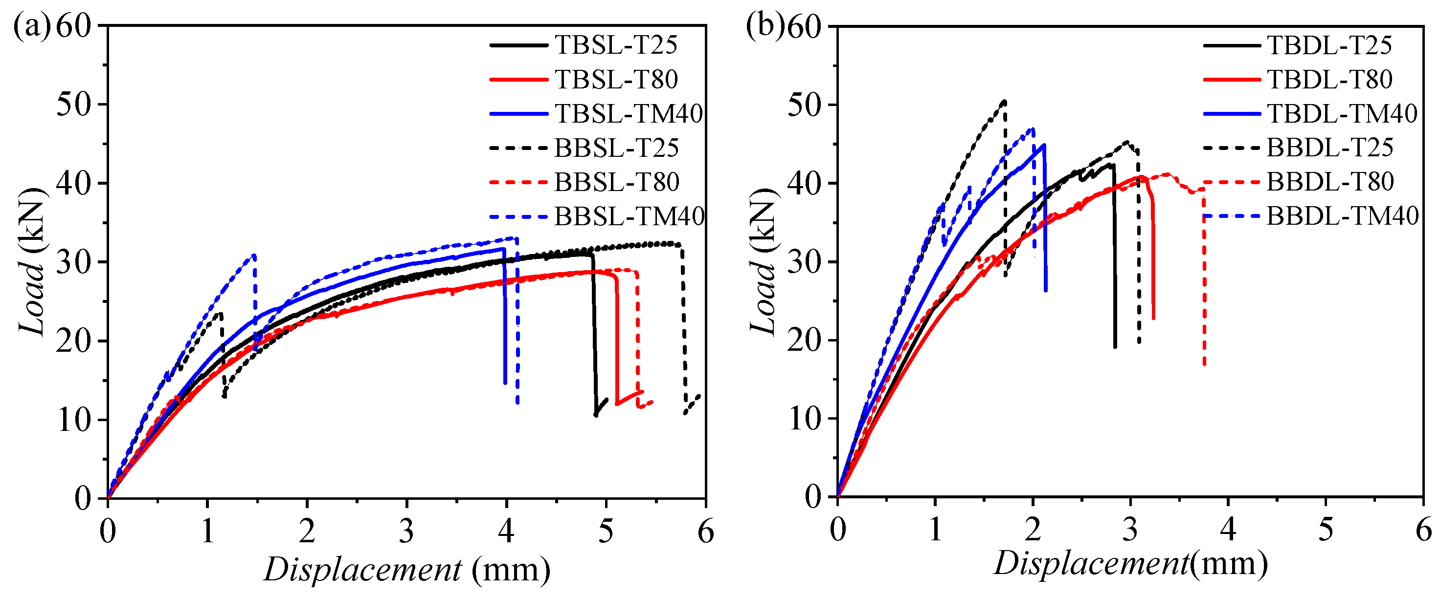
3.3. Tensile Failure Results of OBSL and BBSL Specimens
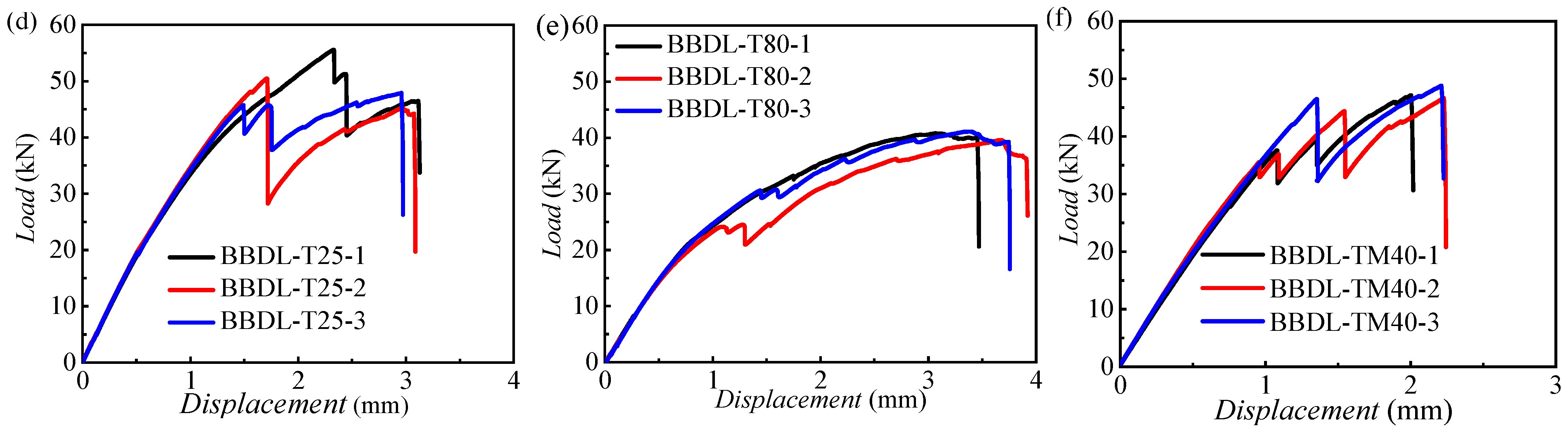
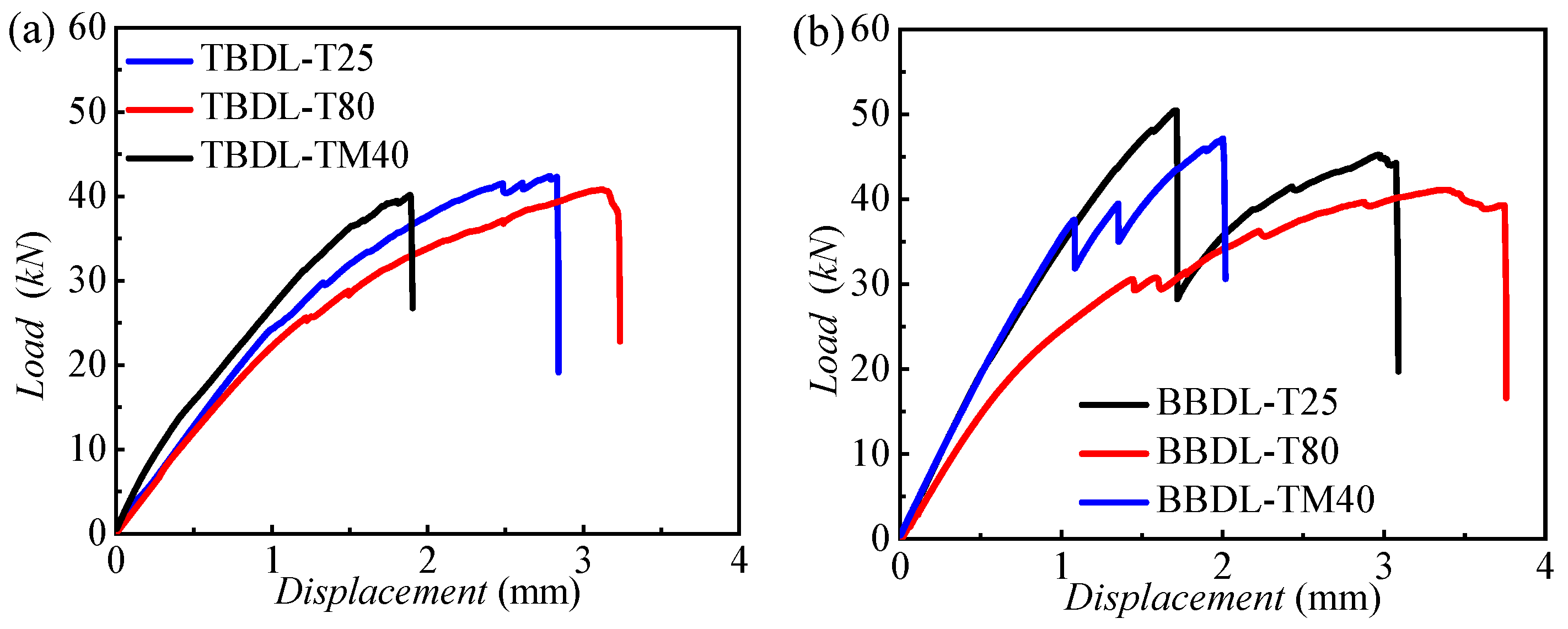
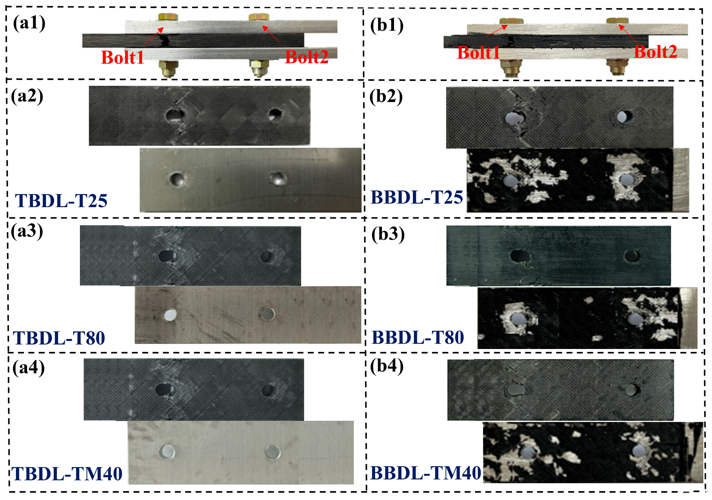
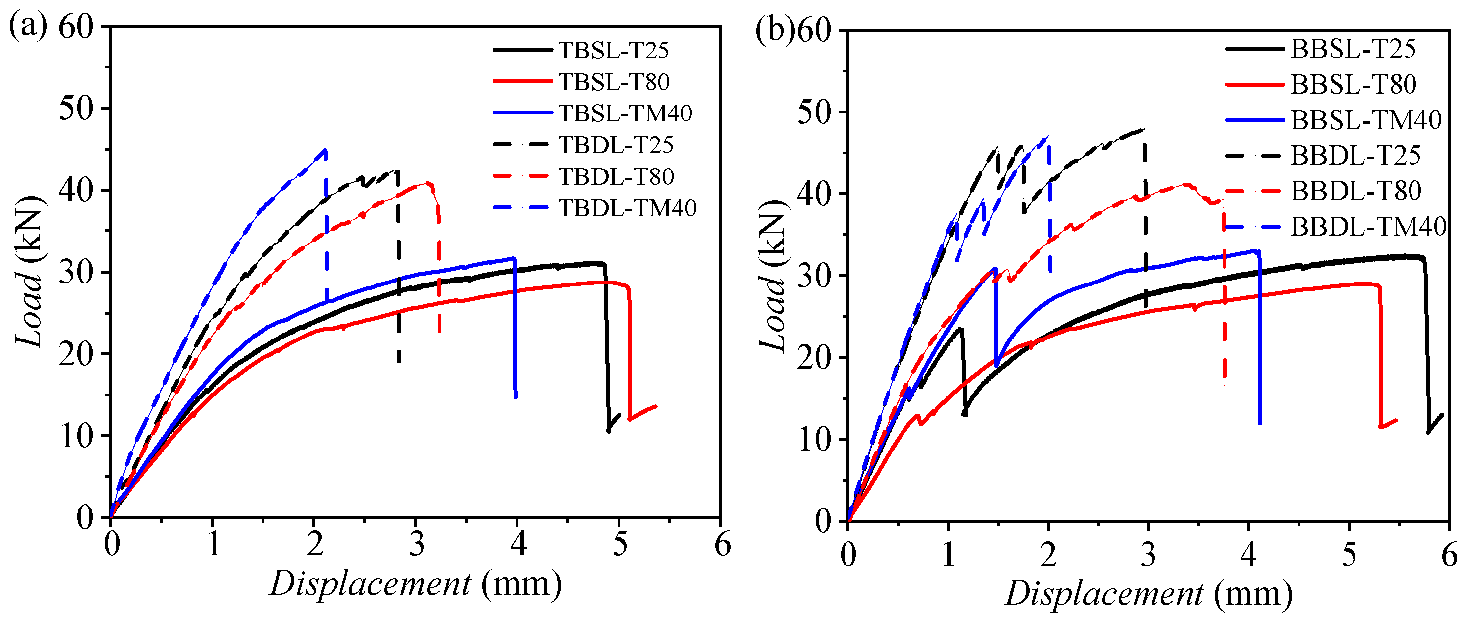
3.4. Tensile Failure Results of TBDL and BBDL Specimens
4. Discussion
5. Conclusions
Author Contributions
Funding
Data Availability Statement
Conflicts of Interest
References
- Chen, H.; Wang, J.; Colin, D.; Li, S.; Drechsler, K. Temperature-Dependent modelling of tension, in-Plane shear, and bending behaviour in non-isothermal thermo-Stamping process simulation of unidirectional UHMWPE fibre reinforced thermoplastic TPU composites. J. Thermoplast. Compos. Mater. 2022, 36, 089270572211422. [Google Scholar] [CrossRef]
- Zhang, Y.; Han, X.; Liu, R.; Li, R.; Zhong, Y.; Cao, D.; Li, S.; Chen, H.; Hu, H. Effect of temperature aging of thermoset UD prepregs on inter-ply friction behavior and formability in prepreg compression molding process. Polym. Compos. 2024, 45, 7861–7878. [Google Scholar] [CrossRef]
- Ekh, J.; Schön, J. Effect of secondary bending on strength prediction of composite, single shear lap joints. Compos. Sci. Technol. 2005, 65, 953–965. [Google Scholar] [CrossRef]
- Zhao, L.; Xin, A.; Liu, F.; Zhang, J.; Hu, N. Secondary bending effects in progressively damaged single-lap, single-bolt composite joints. Results Phys. 2016, 6, 704–711. [Google Scholar] [CrossRef]
- Rezvaninasab, M.; Farhadinia, M.; Mirzaei, A.; Ramzaninezhad, M.; Khamseh, F.; Alaei, M.h. Experimental evaluation of reinforcing the single lap joint in both longitudinal and transverse direction under tensile and bending condition. Int. J. Adhes. Adhes. 2019, 88, 19–25. [Google Scholar] [CrossRef]
- Cao, Y.; Cao, Z.; Zhao, Y.; Zuo, D.; Tay, T.E. Damage progression and failure of single-lap thin-ply laminated composite bolted joints under quasi-static loading. Int. J. Mech. Sci. 2020, 170, 105360. [Google Scholar] [CrossRef]
- Mehrabian, M.; Boukhili, R. 3D-DIC strain field measurements in bolted and hybrid bolted-bonded joints of woven carbon-epoxy composites. Compos. Part B Eng. 2021, 218, 108875. [Google Scholar] [CrossRef]
- Peng, X.; Yong, H.; Zhou, Y. Three-dimensional simulation of single-lap and bridge joints of coated conductor under tension and bending tests. Compos. Struct. 2022, 284, 115146. [Google Scholar] [CrossRef]
- Ulus, H. An experimental assessment of hybrid bolted/bonded basalt fiber reinforced polymer composite joints’ temperature-dependent mechanical performances by static and dynamic mechanical analyses. Int. J. Adhes. Adhes. 2022, 114, 103120. [Google Scholar] [CrossRef]
- Zhang, H.; Song, Z.; Zhang, L.; Liu, Z.; Zhu, P. Effect of hygrothermal environment on the fatigue fracture mechanism of single lap Aluminum-CFRP hybrid (riveted/bonded) joints. Int. J. Fatigue 2022, 165, 107177. [Google Scholar] [CrossRef]
- Blier, R.; Monajati, L.; Mehrabian, M.; Boukhili, R. Strength Optimisation of Hybrid Bolted/Bonded Composite Joints Based on Finite Element Analysis. Materials 2024, 17, 3354. [Google Scholar] [CrossRef] [PubMed]
- Xiang, S.; Cheng, B.; Wang, J.; Li, D.; Li, S.; Yan, X. Investigation on fatigue behavior of GFRP hybrid bonded/bolted joint under shear loading based on nondestructive monitoring test and numerical modeling. Eng. Struct. 2024, 308, 117998. [Google Scholar] [CrossRef]
- Xiang, S.; Cheng, B.; Wang, J.; Li, D.; Yan, X. Experimental and numerical investigation on failure behavior of hybrid bonded/bolted GFRP single-lap joints under static shear loading. Eng. Fail. Anal. 2024, 158, 107969. [Google Scholar] [CrossRef]
- Yokozeki, K.; Hisazumi, K.; Vallée, T.; Evers, T.; Ummenhofer, T.; Boretzki, J.; Albiez, M. Hybrid joints consisting of pre-tensioned bolts and a bonded connection, Part II: Large-scale experiments. Int. J. Adhes. Adhes. 2024, 128, 103523. [Google Scholar] [CrossRef]
- Bambach, M.R. Tension Strength of Multi-Fastener, Single-Lap Joints in Flax and Jute Composite Plates Using Bolts or Rivets. Materials 2025, 18, 2180. [Google Scholar] [CrossRef] [PubMed]
- Mohapatra, D.R.; Behera, S.; Mondal, S. Modified Hashin criteria based 3D damage progression in bolted, bonded and hybrid single-lap joints of woven GFRP laminates. Structures 2025, 78, 109265. [Google Scholar] [CrossRef]
- Wang, X.; Wang, Y.; Ji, Y.; Hu, H.; Cao, D.; Zheng, K.; Liu, H.; Li, S. Modeling Progressive Damage and Failure of Single-Lap Thin-Ply-Laminated Composite-Bolted Joint Using LaRC Failure Criterion. Materials 2022, 15, 8123. [Google Scholar] [CrossRef] [PubMed]
- Cao, D.; Duan, Q.; Hu, H.; Zhong, Y.; Li, S. Computational investigation of both intra-laminar matrix cracking and inter-laminar delamination of curved composite components with cohesive elements. Compos. Struct. 2018, 192, 300–309. [Google Scholar] [CrossRef]
- Cao, D.; Hu, H.; Wang, Y.; Li, S. Experimental and numerical studies on influence of impact damage and simple bolt repair on compressive failure of composite laminates. Compos. Struct. 2021, 275, 114491. [Google Scholar] [CrossRef]
- Duan, Q.; Hu, H.; Cao, D.; Cai, W.; Li, S. A new mechanism based cohesive zone model for Mode I delamination coupled with fiber bridging of composite laminates. Compos. Struct. 2024, 332, 117931. [Google Scholar] [CrossRef]
- Duan, Q.; Hu, H.; Cao, D.; Cai, W.; Xia, J.; Li, S. Modified mode I fracture toughness calculation method for composite laminate with large scale fiber bridging. Compos. Struct. 2024, 349–350, 118521. [Google Scholar]
- Cao, Y.; Zhi, J.; Zuo, D.; Li, X.; Cao, Z.; Wang, Y.; Tay, T.E. Mesoscale modelling of progressive damage and failure in single-lap and double-lap thin-ply laminated composite bolted joints. Compos. Struct. 2023, 316, 117046. [Google Scholar] [CrossRef]
- Mehrabian, M.; Boukhili, R. Quantifying of secondary bending effect in multi-bolt single-lap carbon-epoxy composite joints via, 3.D.-D.I.C. Compos. Sci. Technol. 2020, 200, 108453. [Google Scholar] [CrossRef]
- Jiang, L.; Xiao, S.; Dong, D.; Yang, B.; Chen, D.; Yang, G.; Zhu, T.; Wang, M. Experimental study of bonded, bolted, and hybrid braided CFRP joints with different stacking sequences and lapping patterns. Thin-Walled Struct. 2022, 177, 109408. [Google Scholar] [CrossRef]
- ASTM D5961; Standard Test Method for Bearing Response of Polymer Matrix Composite Laminates. ASTM: West Conshohocken, PA, USA, 2018.
- ASTM D5766; Standard Test Method for Open-Hole Tensile Strength of Polymer Matrix Composite Laminates. ASTM: West Conshohocken, PA, USA, 2018.
- Chamis, C.C. Simplified Procedures for Designing Composite Bolted Joints. J. Reinf. Plast. Compos. 1990, 9, 614–626. [Google Scholar] [CrossRef]


| Specimen Name | Connection Type | Temperature | Label | Specimen Number |
|---|---|---|---|---|
| OHT | Open-hole, No Joint | RT −40 °C 80 °C | OHT-T25 OHT-TM40 OHT-T80 | 3 |
| OBDL | One-bolt, Double-Lap | RT −40 °C 80 °C | OBDL-T25 OBDLTM40 OBDL-T80 | 3 |
| TBSL | Two-bolt, Single-Lap | RT −40 °C 80 °C | TBSL-T25 TBSL-TM40 TBSL-T80 | 3 |
| TBDL | Two-bolt, Double-Lap | RT −40 °C 80 °C | TBDL-T25 TBDL-TM40 TBDL-T80 | 3 |
| BBSL | Bonded–bolted hybrid, Single-Lap | RT −40 °C 80 °C | BBSL-T25 BBSL-TM40 BBSL-T80 | 3 |
| BBDL | Bonded–Bolted hybrid, Double-Lap | RT −40 °C 80 °C | BBDL-T25 BBDL-TM40 BBDL-T80 | 3 |
| Label | Ultimate Load (kN) | Failure Mode |
|---|---|---|
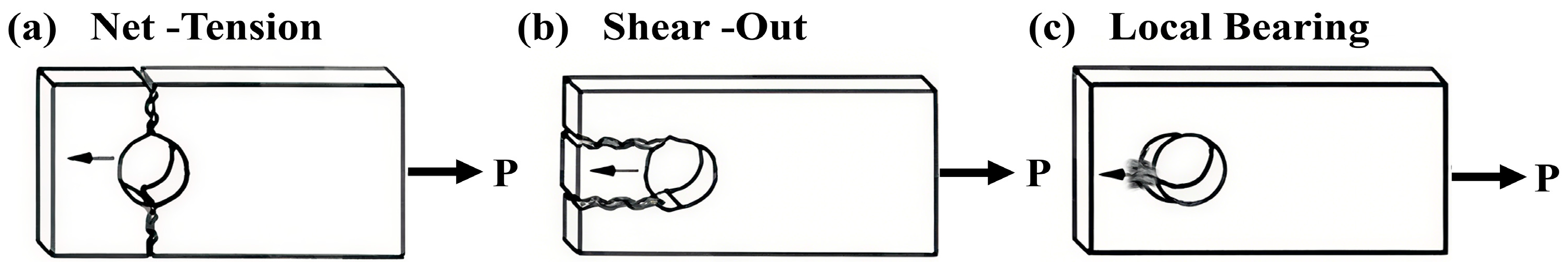
| OHT-TM40 | 72.33 | Net-Tension |
| OHT-T25 | 77.89 | Net-Tension |
| OHT-T80 | 73.66 | Net-Tension |
| OBDL-TM40 | 21.96 | Net-Tension + Local Bearing + Shear-out |
| OBDL-T25 | 24.41 | Net-Tension + Local Bearing + Shear-out |
| OBDL-T80 | 23.70 | Net-Tension + Local Bearing + Shear-out |
| TBSL-TM40 | 31.68 | Net-Tension + Local Bearing |
| TBSL-T25 | 30.59 | Net-Tension + Local Bearing |
| TBSL-T80 | 28.66 | Net-Tension + Local Bearing |
| TBDL-TM40 | 42.70 | Net-Tension + Local Bearing |
| TBDL-T25 | 43.69 | Net-Tension + Local Bearing |
| TBDL-T80 | 40.67 | Net-Tension + Local Bearing |
| BBSL-TM40 | 34.10 | Net-Tension + Local Bearing + Shear-out |
| BBSL-T25 | 32.50 | Net-Tension + Local Bearing + Shear-out |
| BBSL-T80 | 29.00 | Net-Tension + Local Bearing + Shear-out |
| BBDL-TM40 | 47.58 | Net-Tension + Local Bearing + Shear-out |
| BBDL-T25 | 51.27 | Net-Tension + Local Bearing + Shear-out |
| BBDL-T80 | 40.56 | Net-Tension + Local Bearing + Shear-out |
Disclaimer/Publisher’s Note: The statements, opinions and data contained in all publications are solely those of the individual author(s) and contributor(s) and not of MDPI and/or the editor(s). MDPI and/or the editor(s) disclaim responsibility for any injury to people or property resulting from any ideas, methods, instructions or products referred to in the content. |
© 2025 by the authors. Licensee MDPI, Basel, Switzerland. This article is an open access article distributed under the terms and conditions of the Creative Commons Attribution (CC BY) license (https://creativecommons.org/licenses/by/4.0/).
Share and Cite
Wang, M.; Huang, Q.; Duan, Q.; Yang, W.; Cui, Y.; Lyu, H. Experimental Investigation of Failure Behaviors of CFRP–Al Lap Joints with Various Configurations Under High- and Low-Temperature Conditions. Materials 2025, 18, 3467. https://doi.org/10.3390/ma18153467
Wang M, Huang Q, Duan Q, Yang W, Cui Y, Lyu H. Experimental Investigation of Failure Behaviors of CFRP–Al Lap Joints with Various Configurations Under High- and Low-Temperature Conditions. Materials. 2025; 18(15):3467. https://doi.org/10.3390/ma18153467
Chicago/Turabian StyleWang, Mingzhen, Qiaosheng Huang, Qingfeng Duan, Wentao Yang, Yue Cui, and Hongqiang Lyu. 2025. "Experimental Investigation of Failure Behaviors of CFRP–Al Lap Joints with Various Configurations Under High- and Low-Temperature Conditions" Materials 18, no. 15: 3467. https://doi.org/10.3390/ma18153467
APA StyleWang, M., Huang, Q., Duan, Q., Yang, W., Cui, Y., & Lyu, H. (2025). Experimental Investigation of Failure Behaviors of CFRP–Al Lap Joints with Various Configurations Under High- and Low-Temperature Conditions. Materials, 18(15), 3467. https://doi.org/10.3390/ma18153467