
Issues Relative to the Welding of Nickel and Its Alloys


Abstract
1. Introduction
2. Classification, Features and Applications of Ni and Ni-Based Alloys
2.1. Classifying Ni and Its Alloys
2.1.1. CP Ni
- Batch soft-annealing in bell-type furnaces: 705–760 °C; 2–6 h; AC.
- Continuous soft-annealing: 815–925 °C; 5 min; AC/WQ.
- Stress relieving: 480–705 °C; 30–120 min; AC.
- Stress equalizing: 260–480 °C; 1–2 h; AC.
- Postweld annealing: 705 °C; AC.
2.1.2. SSS Ni-Based Alloys
- Ni-Cu based alloys
- Soft annealing: 700–900 °C;
- Tempering: 550–650 °C.
- Soft material (140–180 HBW)—as-forged and quenched or annealed forgings, annealed or hot-rolled rods, large cold-drawn rods, and soft-temper wire and strip:
- o
- Age hardening: 580–610 °C; 16 h;
- o
- Furnace cooling: 12 °C/h down to 480 °C;
- o
- Air cooling.
- Moderately cold-worked material—cold-drawn rods, half-hard strip, cold-upset pieces, and intermediate-temper wire:
- o
- Age hardening: 580–610 °C; 8 h;
- o
- Furnace cooling: 12 °C/h down to 480 °C;
- o
- Air cooling.
- Fully cold-worked material (260–325 HBW, 25–35 HC)—spring-temper strip, spring wire, or heavily cold-worked pieces such as small, cold-formed balls:
- o
- Age hardening: 520–540 °C; 6 h;
- o
- Furnace cooling: 12 °C/h down to 480 °C;
- o
- Air cooling.
- Ni-Mo-based alloys
- Ni-Fe-based alloys
- Ni-Cr-Fe alloys
- Ni-Cr-Fe alloys exhibit remarkable strength at elevated temperatures and possess the capability to withstand oxidation, carburization, and various forms of high-temperature corrosion. The most recognized is alloy 800 (UNS N08800), along with its variants 800H (UNS N08810) and 800HT (UNS N08811). (Recently, such alloys have been categorized as stainless steels due to their elevated Fe content accompanied mainly by Ni and Cr). Stainless steel 800H exhibits exceptional high-temperature strength and high resistance to high-temperature oxidation.
- Ni-Cr-Fe (along with Mo and Cu) alloys that offer outstanding corrosion resistance in certain applications. Arguably, the most recognized is alloy 825 (UNS N08825), known for its high resistance to sulphuric acid. Alloy G3 (UNS N06985) provides high corrosion resistance against commercial phosphoric acids and various complex solutions with strong oxidizing acids.
- Cr (11.5–17%)-Fe alloys with carefully controlled carbon content. Can be heat-treated to a magnetic martensite structure and are therefore known as martensitic stainless steels.
- Cr (17–27%)-Fe alloys with low carbon content. They are non-hardenable by heat treatment. Their crystal structure is magnetic ferrite and therefore are known as ferritic stainless steels.
- Cr (16–26%)-Ni (6–22%)-Fe alloys with low carbon content. They are non-hardenable by heat-treatment. They exhibit crystal structure of nonmagnetic austenite and are therefore called austenitic stainless steels.
- Annealing—softens the material. Proper treatment takes 15 min in about 1010 °C.
- Solutioning—dissolves the carbides and increases grain size, which is good for creep resistance and rupture strength. Proper treatment takes 1 to 2 h at 1090–1150 °C.
- Solution-treatment: 1100–1200 °C.
- Annealing: 1000–1100 °C.
- Soft annealing: 980–1150 °C; 30–60 min.
- Solutioning: 1150 °C; 2 h.
- Annealing: 925–1010 °C; 1 h.
- Air cooling.
- Age hardening: 620 °C; 8 h.
- Furnace cool to 650 °C.
- Hold at 650 °C until furnace time for the entire age-hardening cycle equals 18 h.
- Air cooling.
- Annealing: 1035–1065 °C; 1 h.
- Air cooling.
- Age hardening: 760 °C; 10 h.
- Furnace cool to 650 °C.
- Hold at 650 °C until furnace time for the entire age-hardening cycle equals 20 h.
- Air cooling.
- Annealing: 1010 °C; 2 h.
- Water Quenching.
- Age hardening: 780–800 °C; 6–8 h.
- Air cooling.
- Ni-Cr-Mo-W alloys
- ▪ Solution-treatment: 980–1040 °C 0.5–4 h; for sizes up to 25 mm WQ or AC, for sizes above 25 mm WQ.
- ▪ Age-hardening: 730–750 °C for 8 h; Furnace cooling: 55 °C/h for 2 h; Age-hardening: 610–630 °C for 8 h; AC or WQ.
- ▪ Precipitation temperature: 760 °C.
- ▪ Batch annealing in bell-type furnaces: Cool rapidly through the range between 760 and 540 °C to ensure freedom from sensitization. Alloys 800H and 800HT are not susceptible to thermal cracking.
- The first: 1150 °C for 10 min, air cooling.
- The second: 1150 °C for 2–4 h, air cooling.
- Solution annealing: 1107–1135 °C.
- Soft annealing: 1065 ± 14 °C; 30 min; WQ.
- Ni-Fe-Cr-Mo alloys
- Solution-treatment: 1120 ± 14 °C, 30 min, WQ.
- Solution-treatment: 1100–1180 °C; rapid air cool/water quench.
- Solution-treatment: 1135–1163 °C; 30 min; water quench.
- Annealing: 1180–1200 °C; water quench.
- Ni-Cr-Co-Mo alloys
- Continuous soft-annealing: 1120–1175 °C; 30–60 min; air cool/water quench
- Batch soft-annealing in bell-type furnaces: 1120–1175 °C; 1–3 h; air cool
- Intermediate annealing: 1040 °C
- Solution-treatment according to ASME SB 176: 1140–1232 °C—to achieve an austenitic matrix without carbide precipitates.
2.1.3. PS Ni-Based Alloys
- Ni-Cu-Al-Ti alloys
- ▪
- Soft material (140–180 HBW)—as-forged and quenched or annealed forgings, annealed or hot-rolled rods, large cold-drawn rods, and soft-temper wire and strip:
- o
- Age hardening: 580–610 °C; 16 h.
- o
- Furnace cooling: 12 °C/h down to 480 °C.
- o
- Air cooling.
- ▪
- Moderately cold-worked material—cold-drawn rods, half-hard strip, cold-upset pieces and intermediate-temper wire:
- o
- Age hardening: 580–610 °C; 8 h.
- o
- Furnace cooling: 12 °C/h down to 480 °C.
- o
- Air cooling.
- ▪
- Fully cold-worked material (260–325 HBW, 25–35 HC)—spring-temper strip, spring wire or heavily cold-worked pieces such as small, cold-formed balls:
- o
- Age hardening: 520–540 °C; 6 h.
- o
- Furnace cooling: 12 °C/h down to 480 °C.
- o
- Air cooling.
- Ni-Cr-Al-Ti
- Ni-Fe-Cr-Nb-Al-Ti
2.1.4. The Specialty Ni-Based Alloys
- Ni-aluminides
- (a) Transformation of martensite
- (b) heat treatment
- Oxygen dispersion strengthened Ni alloys
3. Welding Characteristics of Ni and Ni-Based Alloys
- Weldability
- Weldability tests
- -
- Butt joint with full penetration,
- -
- T-joint with full penetration,
- -
- Branch connection with full penetration,
- -
- Fillet welds [149].
- transverse tensile test (2 specimens),
- transverse bend test (4 specimens),
- impact test (2 set of 3 specimens),
- hardness test (1 specimen),
- macroscopic examination (2 specimens).
- Radiographic Testing:
- ASTM E165: Standard Practice for Radiographic Examination of Welds.
- ASTM E1032: Standard Practice for Radiographic Examination of Weldments Using Industrial X-ray Film.
- Ultrasonic Testing:
- ASTM E709: Standard Practice for Ultrasonic Inspection of Weldments.
- Other NDT Methods:
- ASTM E1312: Standard Practice for Electromagnetic (Eddy-Current) Examination of Ferromagnetic.
- ASTM E2261: Standard Practice for Examination of Welds Using the Alternating Current Field.
- Welding techniques employed for connecting Ni and Ni-based alloys
- -
- Diffusion bonding
- -
- Plasma arc welding
- -
- GTAW
- -
- Existing processes are costly and time-consuming.
- -
- Nickel-based super alloy products are high value.
- -
- Tool wear and failure are noted as a common issue.
- -
- During tensile tests, achieving failure outside FSW/P stir zone is possible.
- -
- Lack of commonality in FSW/P efforts.
- ▪
- Travel Speed: 0.42 mm/s.
- ▪
- Temperature Control: 800 to 850 °C.
- ▪
- Axial Force: 62 kN (based on visual quality).
- ▪
- Rotational speed: 50–100 RPM (output variable from temperature control).
- ▪
- Tool: MegaStir PCBN Q60 FSW Tools w/4 and 6 mm pin length.
- ▪
- Full solution anneal.
- ▪
- Step 1: 1010 °C for 2 h then air cooled.
- ▪
- Step 2: 788 °C for 8 h then air cooled.
- ▪
- The FSP nugget was harder than the base material after FSP.
- ▪
- After heat treatment, microhardness slightly varied from the base material to the nugget.
- ▪
- Both post-heat treatment thermal exposure methods used exhibited similar observations.
- ▪
- Upon 760 °C exposure, hardness increase was observed.
- ▪
- Upon 871 °C exposure, a reduction in hardness was noted due mainly to coarsening of the γ′ precipitates (~200 ± 150 nm).
- ▪
- All these observations were similar for both the base metal and the processed region.
- ▪
- Mo-rich phases should be prevalent in 871 °C but not in 760 °C.
- ▪
- M6C occurs from 780 °C to 1080 °C.
- ▪
- Processed region tensile properties were similar to the base metal, resulting in a joint efficiency of 100%.
- ▪
- All the cross-weld FSP samples failed in the base metal.
- ▪
- The lowest local strain was observed in the processed region.
- ▪
- The highest local strain was noted in the base metal.
- ▪
- Grain boundary fracture and sample failure were primarily in the banded region.
- ▪
- As FSP (before creep testing), mostly, MC and M23C6 precipitates in the banded region.
- ▪
- Differences appear after creep testing, including:
- -
- Presence of Mo-rich phases along grain boundary (GB) and grain
- -
- interior.
- -
- Platelet like phase could be µ phase ((Ni,Co)7Mo6) or σ (FeCrMo.CrCo).
- Ni-based superalloys can be successfully friction stir welded and processed
- Low rotation speeds and processing temperatures are important to successful FSW/P of nickel-based superalloys.
- FSW/P of solution annealed Haynes 282 significantly increases hardness in the stir zone. However, the standard two-step heat treatment yields similar hardness from the base material through the FSW/P regions.
- FSW/P of Haynes 282 plus post-solution anneal + FSW/P two-step heat treatment (standard fabrication process) yields FSW/P mechanical properties (creep and tensile) that can meet base material properties.
- FSW/P can heal defects in cast material.
- Inconel 617 is similarly processable by FSW/P but appears to require higher processing temperatures.
- Differences between various welding processes and their correlations with the weldability of Ni-based alloys.
- SMAW—uses a consumable, flux-coated electrode to create an arc, shielding the weld pool with the flux. It is suitable for various materials and positions, but has slower welding speeds and less precise control than other arc methods [183,184,186,187,188,189,190,191,192,193,194,197,198,199,200,201,202,203,204]. It can be utilized for welding Ni-based alloys, but precise choice of electrodes and settings is essential, particularly for precipitation-hardened alloys. Ni alloys typically melt at lower temperatures than steel, and require less heat input when welding compared to steel. Excessive heat application may result in problems such as the loss of alloying elements and heightened distortion. Choosing the appropriate electrode is essential for attaining the desired characteristics of the weld. Ni-based electrodes are frequently employed, and their formulation must be selected to complement the base metal and the intended welding properties. The SMAW process can affect the weld microstructure, with elements such as heat input and cooling rate impacting grain size and phase development. In certain situations, post-weld heat treatment might be required to enhance characteristics such as strength and toughness. In dissimilar welding of Ni-based alloys to different materials, selecting the appropriate electrode and welding parameters is even more essential. Particular attention must be paid to the risk of cracking or other problems at the junction. The SMAW process for nickel alloys may be susceptible to specific defects, including porosity or cracking. Effective welding methods, such as controlling parameters and preparing joints, are crucial to reduce these problems [196,205,206,207,208,209,210,211,212,213,214,215,216,217,218,219,220,221,222,223,224,225,226,227,228]
- GTAW—uses a non-consumable tungsten electrode and inert shielding gas to create a precise, controlled arc, often requiring a skilled operator. It is excellent for joining thin sections of Ni-based alloys and other materials [185,199,229,230]. The arc formed between the tungsten and the workpiece generates the necessary heat for melting the base materials. A filler metal can be added to the weld pool as needed. The process is shielded by an inert gas, typically argon or helium, to protect the molten weld from contamination. GTAW/TIG is known for its precision and ability to create high-quality welds, making it suitable for a variety of materials and applications. Commonly employed for welding thin and non-ferrous materials, such as nickel alloys, because of its accuracy and capacity to regulate heat input [196,198,229,231,232]. GTAW (Gas Tungsten Arc Welding) factors such as current, travel speed, and shielding gas greatly influence the microstructure and weldability of nickel (Ni) alloys. These factors affect grain size, phase development, and the occurrence of defects like cracks or porosity, which in turn influence mechanical characteristics such as strength, hardness, and ductility [233,234,235,236].
- PAW—is similar to GTAW but uses a more concentrated arc and a plasma gas to create a higher energy, more focused weld. This process can be automated and is used for thicker sections of Ni-based alloys [184,185,237]. It is suitable for welding nickel alloys, offering high energy concentration and deep infiltration [195,238,239,240]. The PAW process parameters strongly influence the microstructure and weldability of Ni-based alloys. These consist of welding current, welding speed, plasma gas flow rate, and the composition of the shielding gas. Tuning these parameters is essential for producing a quality weld that exhibits the required mechanical attributes and microstructural properties [195,196,239,241,242,243,244,245,246].
- GMAW—uses a continuous, consumable wire electrode and shielding gas to create the arc. It is a faster process than SMAW and GTAW, making it suitable for high-volume production [197,198,200]. Such an alternative, appropriate gas-shielded method is frequently employed for the thicker parts of nickel alloys [196,205,247]. GMAW (Gas Metal Arc Welding) of nickel alloys is affected by various process parameters that impact both the microstructure and weldability. Essential parameters consist of welding current, voltage, travel speed, shielding gas flow rate, and wire feed rate. Adjusting these parameters is essential for attaining the intended weld characteristics, including strength, ductility, and crack resistance [248,249,250,251,252,253,254,255].
- FCAW—utilizes a continuous, flux-cored wire electrode that provides shielding gas and filler metal. It is versatile, suitable for outdoor welding, and can be used on dirty or contaminated surfaces [183,184,185,202,203,220,256,257,258,259]. The weldability and microstructure of nickel-based alloys during FCAW are greatly affected by the composition of the filler metal and welding parameters. Factors such as current, voltage, travel speed, and shielding gas composition, along with the type and proportion of alloying elements in the filler wire, significantly influence the microstructure, mechanical properties, and crack resistance of the weld [250,260,261,262].
- SAW—uses a submerged arc, shielded by a blanket of flux. It is highly productive and suitable for thick plates of Ni-based alloys [186,187,188,189,190,191,192,193,194,256,263,264]. It is typically limited to solid-solution strengthened nickel alloys because of the risk of cracking in precipitation-hardened alloys [196,205,245]. The microstructure and weldability of Ni-based alloys in submerged arc welding (SAW) are affected by various essential factors, such as chemical composition, heat input, and welding conditions. These elements influence the solidification characteristics, grain patterns, phase development, and ultimately, the mechanical attributes and corrosion resistance of the weld [217,245,265,266,267].
- EBW—uses a focused beam of high-energy electrons to melt and fuse metals, offering high precision and deep penetration, especially for Ni-based alloys [268,269,270]. It is very effective for welding nickel-based superalloys, creating deep, narrow welds with little distortion [5,195,271,272,273,274]. According to [245], EBW results in a joint that features deep penetration, a narrow fusion zone and heat-affected zone, along with minimal residual stresses thanks to a more uniform heat distribution, making EBW joints potentially better than conventional welded joints. In IN825, EBW joints are generally superior to GTAW welds, as the increased heat input resulted in a coarser microstructure and crack formation. However, when process parameters are not fine-tuned, achieving welds without cracks becomes challenging. This is especially difficult in single-crystal alloys, since GTA welds are typically free of cracks, whereas EBW welds contain stray grains that cause cracking. The unique aspects of the EBW process, including the need for a vacuum chamber, result in superior joint quality, even when contrasted with LBW. A comparison of laser and electron beam welding on thick joints composed of precipitation-strengthened Waspaloy and Udimet 720Li showed that the EBW joints exhibited lower porosity, though greater distortion was observed in the joints. The fusion zone also varies in shape and size. The factors influencing the process are categorized into two categories: beam characteristics (such as accelerating voltage and beam current) and joint properties (including welding speed, welding width, vacuum pressure, and preheating temperature). Statistical methods can be employed to merge the parameters efficiently. The combination of various values for beam current, accelerating voltage, welding speed, and beam oscillation showed that the accelerating voltage, along with beam current, significantly influences both the penetration and the width of the beam. The beam oscillation was not as significant; however, it influenced the crack susceptibility for Inconel 718 welded by EBW in the solution-treated state. The oscillation of the elliptical beam enhanced tensile strength and ductility at room temperature regardless of the heat treatment.
- LBW—utilizes a laser beam to melt and fuse metals, providing high precision and controlled heat input [200,268,269,275,276,277]. Like EBW, LBW provides high power density and accuracy for welding nickel alloys and other materials, especially in aerospace and various high-performance uses [195,278,279,280]. According to [245], the CO2 gas laser formerly used for welding tasks has been replaced by solid-state lasers today, like the Nb:YAG laser. Lately, fiber lasers have become popular due to their ability to enable rapid welding and their notable stability and precision. The fiber laser possessed enhanced melting efficiency and reduced the minimal heat input needed for complete penetration welds of Inconel 617 butt joints relative to the CO2 laser. Gas lasers have been effectively utilized for welding various superalloy joints, including Inconel 625, Inconel 718, and Nimonic. Examples of Nd:YAG laser applications include Inconel 718, Inconel 600, and NiTi shape memory alloy. The Nd:YAG laser demonstrated the ability to produce superior quality joints compared to various other laser types. A higher uniformity of the beads was noted in Inconel 718 joints welded with the Nb:YAG laser compared to the gas laser. This involves reduced residual stresses and the absence of microfissuring, which is a significant concern in laser welding. The Nd:YAG laser offers several benefits, including a high-energy absorption rate due to its low reflectivity, faster welding speeds, and reduced residual stress compared to CO2 lasers. These benefits render the Nd:YAG laser more practical and appropriate for on-site use and factory automation in high-volume manufacturing across various industrial applications. Obtaining smooth welds depends on the selection of laser parameters, the conditions before welding, and the heat treatments after welding.An appropriate adjustment of the laser welding settings ensures the quality of the welds. ANOVA analysis or DOE techniques enable the identification of optimal parameter combinations. The key factors include laser power and welding speed; however, additional elements are also important, including shielding gas flow rate, shielding gas pressure, focal position, and pulsation frequency.
- -
- FRW—creates a weld by applying pressure and rotating two pieces of metal together, producing a solid-state weld without melting. It is good for joining Ni-based alloys and other materials [200,281,282]. It can be realized as the Inertia Friction Welding (IFW) [1] or the Linear Friction Welding (LFW) [283]. The main factors influencing the friction welding of Ni alloys include friction pressure, upset pressure, burn-off length, rotational speed, friction duration, and forge pressure. These factors directly impact the heat input, plastic deformation, and ultimately, the microstructure and mechanical characteristics of the weld [284,285,286,287].
- FSW—uses a rotating tool to stir and consolidate the material being joined, producing a strong, solid-state weld without melting. It is suitable for joining Ni-based alloys and other materials [200,282,288,289]. It generates high-quality welds with little distortion, presenting a favorable alternative for connecting nickel alloys [5,290,291,292]. Friction stir welding (FSW) of Ni-based alloys and others is affected by various essential parameters that impact the microstructure and weldability. These factors encompass rotational speed, welding speed, tool shape, and axial force. Adjusting these parameters is essential for producing high-quality welds with preferred mechanical characteristics [293,294,295,296].
- Application requirements—certain applications may demand the unique properties of a specific process, such as the deep penetration of EBW or the precision of LBW [269].
- The effect of welding processes on the microstructure of Ni-based alloys
- ▪
- Heat Input:—welding processes introduce significant heat into the weld zone, affecting the microstructure. Higher heat input can lead to coarser grain size and potentially the formation of undesirable phases.
- •
- Cooling rate—the cooling rate after welding also influences the microstructure. Slow cooling can promote the formation of larger grains and phases, while rapid cooling can lead to finer microstructures and the formation of martensite.
- •
- Filler metal—the type and composition of the filler metal used in welding can significantly impact the weld microstructure and phase composition.
- F-SMAW, GMAW, GTAW, PAW, FCAW—these processes can result in a microstructure consisting of the primary phase, such as the Ni-based alloy’s base matrix, and potentially secondary phases like carbides or intermetallic compounds. The specific microstructure depends on the alloy’s composition and welding parameters.
- EBW, LBW—these methods can create very fine-grained microstructures due to rapid cooling and high energy density.
- Friction Welding (FRW) and Friction Stir Welding (FSW)—these solid-state welding processes can produce microstructures characterized by deformation bands and grain refinement in the heat-affected zone.
- Elevated current, which may cause excessive heat input, leading to a coarser grain structure in the weld zone (WZ) and heat-affected zone (HAZ), which might decrease strength and ductility. It may also elevate the likelihood of solidification cracking, particularly in alloys prone to cracking.
- Low voltage, which might not deliver adequate fusion, resulting in insufficient penetration and possible welding flaws. It may lead to a reduced grain size, yet it might not be enough to obtain the required mechanical properties.
- High travel speed, which lowers heat input, potentially resulting in a finer grain structure in the WZ and HAZ. Nonetheless, it could also decrease penetration and result in insufficient fusion.
- Leisurely pace of travel augments heat input, which may result in a rougher grain structure and heightened likelihood of solidification cracking. It also enables improved integration and infiltration.
- Protective gas in the form of Ar, frequently utilized for GTAW of Ni alloys, offering effective protection against environmental contamination. Alternatively, He provides a greater heat input than argon, which can be beneficial for thicker materials or challenging alloys to weld. Nevertheless, it may also elevate the risk of porosity if not adequately managed. Gas mixtures can also be customized to enhance welding characteristics for specific alloys and uses.
- The kind of tungsten electrode employed (e.g., thoriated, ceriated) can influence arc stability and the qualities of the weld pool.
- The electrode’s angle in relation to the workpiece can affect arc direction, penetration depth, and the shape of the bead.
- Heating Ni alloys beforehand can decrease thermal stresses and enhance weldability, particularly for thicker materials.
- Post-welding heat processing may be essential to enhance the microstructure and boost mechanical properties.
- Elevated current typically results in more heat input, which may create broader weld beads, greater penetration, and coarser grain structures in the Heat Affected Zone (HAZ).
- Increased welding speeds, which may lead to shallower penetration and finer grain structures because of lower heat input and quicker solidification periods.
- The plasma gas flow rate impacts the characteristics of the plasma jet, altering the shape of the weld pool, the penetration depth, and the overall quality of the weld. Increased flow rates may result in greater penetration but could also heighten the chance of porosity.
- Selecting a shielding gas (such as Argon, Helium, or combinations) affects the stability of the weld pool, its oxidation resistance, and the development of particular microstructural phases. It also influences the heat exchange and cooling speed of the weld.
- In powder-fed PAW, the rate of powder feed influences the dilution of the base metal and the makeup of the weld deposit. Accurate regulation of the powder feed rate is crucial for obtaining the targeted chemical composition and mechanical characteristics.
- The gap between the welding torch and the workpiece affects the heat spread and the properties of the weld pool. Keeping a steady torch standoff is crucial for even welding.
- In pulsed PAW, parameters such as frequency and current, which can be modified to regulate heat input, weld pool dimensions, and solidification speed, affect the microstructure and reduce the risk of cracking.
- A higher welding current typically results in deeper weld penetration, but may also raise the risk of cracking, particularly in nickel-based alloys, because of their sensitivity to thermal input.
- Welding voltage influences arc stability and the shape of the weld bead. Increased voltage may produce a broader weld bead, whereas decreased voltage can yield a thinner, more concentrated weld.
- Increased travel speeds lead to reduced heat input and can enhance the microstructure of the weld, though they may also cause incomplete fusion and defects if not managed correctly.
- Shielding gas prevents atmospheric pollutants from affecting the weld pool. The correct flow rate is vital for avoiding porosity and guaranteeing a clean weld.
- The speed of the wire feed directly regulates the quantity of filler metal introduced to the weld, affecting both the size of the weld and the chemical makeup of the weld metal.
- Pre-heating the workpiece, which can lower thermal stresses and avoid cracking, while keeping proper interpass temperatures, aids in controlling heat input during multi-pass welding.
- Increased current and voltage, which typically boost heat input, resulting in a larger weld pool and greater penetration. High current may result in the loss of alloying components and increased porosity. Higher voltage can enhance arc stability and encourage grain development.
- Higher travel speeds decrease heat input, leading to faster cooling and possibly increased hardness. Inadequate travel speed can result in excessive heat input, causing warping and fracturing.
- The selection of shielding gas, which can impact weld penetration, bead formation, and the development of oxides and nitrides, affects the microstructure and mechanical characteristics.
- The makeup of the flux-cored wire, especially the inclusion of elements such as Ni, Cr, Mo, and Nb, can considerably influence the phase changes during cooling, thereby impacting the weld’s strength, hardness, and resistance to corrosion.
- Heat input, depending on current, voltage, and travel speed, is essential in influencing the microstructure and characteristics of the weld. Maximizing heat application is crucial for attaining the preferred penetration, grain structure, and phase arrangement.
- Preheating, which helps decrease thermal stresses and enhances microstructure while keeping the right interpass temperature, is vital to prevent excessive cooling rates or overheating.
- Alloying elements such as Nb, C, and others are vital in influencing the solidification process, phase changes, and the emergence of secondary phases like NbC and Laves phases. These stages can greatly influence the ductility and overall effectiveness of the weld.
- Carbon concentration substantially impacts weldability, influencing phase development and microstructure.
- Ni concentration enhances strength and low-temperature impact toughness by encouraging the development of acicular ferrite.
- The heat supplied during SAW influences the grain size and distribution, phase changes, and the development of acicular ferrite. Increased heat input can result in larger grains and a greater proportion of acicular ferrite, which might enhance hardness and tensile strength, yet could reduce impact toughness and corrosion resistance.
- The rate of welding impacts the cooling rate and solidification duration, which, in turn, affect grain size and microstructure.
- Welding voltage and current influence the energy input and melt pool properties, thereby impacting the weld bead dimensions and depth.
- The makeup of the shielding gas, especially the levels of oxygen and carbon dioxide, can impact oxide formation and alter the microstructure of the welded metal.
- Greater rotational speeds result in elevated friction and heat production at the weld interface. Excessive speed can lead to grain coarsening and diminish weld strength.
- The length of friction directly affects the level of heat generated. Extended friction durations can result in excessive heat and possibly unfavorable microstructural alterations.
- Friction pressure governs the contact force between the moving and fixed components. It affects the speed of heat production and plastic deformation. According to a study published by Springer, greater friction pressure typically results in improved bonding and enhanced tensile strength. Used following the friction stage, this pressure solidifies the weld and guarantees a strong joint. The strain rate during the welding process is also linked to forge pressure.
- Length of burn-off characterizing the quantity of material that is “removed” or displaced during the friction process. It quantifies plastic deformation and material loss, and is affected by friction duration, pressure, and rotational speed.
- Rotation speed impacts the thermal input and material movement during FSW. Elevated speeds can result in greater heat input, which may enhance grain refinement in the stir zone (SZ), but could also lead to issues such as voids or cracking if the speed exceeds certain limits. Reduced speeds can cause inadequate heat generation, resulting in poor mixing and weak connections.
- Welding speed establishes the tool’s dwell time in the weld area, consequently affecting the heat input and material blending. Increased welding speeds may lower heat input, which could result in incomplete mixing and flaws, whereas decreased speeds can raise heat input and potentially cause excess material flow and warping.
- Tool configuration, including the length of the pin, the diameter of the pin, and the diameter of the shoulder, all influencing the flow of the material and the generation of heat. The design of tools is essential for ensuring adequate material blending and reducing flaws. For instance, a wider shoulder diameter can enhance heat input and material flow, whereas a longer pin can influence the depth of the stirred region.
- Axial load regulates the force exerted by the tool on the workpiece, affecting material flow and the occurrence of defects. Increased axial force may enhance material mixing and consolidation; however, too much force can result in tool wear or material ejection.
- Ni-based Alloys—the primary phase in Ni-based alloys is typically the Ni-rich matrix, which can be either a face-centered cubic (FCC) phase or a combination of FCC and other phases depending on the alloy’s composition.
- Welding effects—welding can alter the primary phase by promoting phase transformations or precipitating secondary phases within the matrix.
- Carbides—such as MC or MX, can precipitate in the weld zone, especially in alloys with high carbon content.
- Intermetallic Compounds—such as sigma phase (σ) or chi phase (χ), can also form depending on the alloy composition and welding conditions.
- Oxides—depending on the welding process and atmosphere, oxides can also form in the weld zone, particularly in GTAW or PAW.
- SMAW, GMAW, GTAW—these are the most commonly used arc welding processes. They can induce varying degrees of heat input, affecting the microstructure and phase transformations in Ni-based alloys.
- FCAW—this process, similar to SMAW and GMAW, can be used to weld Ni-based alloys, but its flux composition and welding parameters can influence the weld microstructure.
- EBW, LBW—these welding methods offer high energy density and can result in rapid solidification and fine-grained microstructures.
- FRW, FSW—these solid-state welding processes can produce microstructures with deformation bands and grain refinement in the heat-affected zone.
- Selective laser melting
- Powder Bed: A layer of Ni-based alloy particles is distributed over a fabrication platform.
- Laser Scanning: A laser beam precisely melts the powder based on a 3D model, forming the intended layer.
- Layer-by-Layer Construction: The procedure continues, layer by layer, until the finished component is achieved.
- Inert Atmosphere: SLM is frequently conducted in an inert atmosphere (such as nitrogen or argon) to avoid oxidation.
- Essential factors for SLM for Ni-based alloys:
- Microstructure [359]: SLM can create equiaxed or columnar grain structures based on process parameters such as scanning speed, hatch distance, and laser energy.
- Process Specifications [359]: Enhancing these parameters is essential to reduce flaws such as cracks, pores, and construction defects.
- Advantages of SLM for Ni-based alloys include:
- Geometries that are intricate: SLM allows for the fabrication of complex forms and patterns that are challenging to achieve using conventional techniques [372].
- Exemplary of Ni-based alloys applicable to SLM comprise:
- NiTi: high-quality NiTi alloys can be in situ synthesized with reduced manufacturing defects, the formation of Ni4Ti3 precipitates, and improved pseudoelasticity and microhardness [374].
- Ni-Nb Alloys: Studies have also concentrated on the SLM of binary Ni-Nb alloys as a substitute for Ni-containing superalloys [377].
3.1. The Weldability of CP Ni
- Porosity
- Craking issues
- Cracking during the solidification of weld metal in CP Ni
3.2. Weldability of Ni Alloys
3.2.1. Weldability of SSS Ni Alloys
- -
- Solid solution welding materials: ERNiCrMo-10, ENiCrMo-10;
- -
- Clad Arc Welding Rod: E NiCrMo-10;
- -
- Unclad arc welding electrode: ENiCrMo-10;
- -
- TIG wire: ERNiCrMo-10, ENiCrMo-10;
- -
- MIG/MAG wire: ERNiCrMo-10, ENiCrMo-10.
3.2.2. Cracking
- Cracking during the weld metal solidification in SSS Ni alloys
- -
- appropriate choice of filler metal that can reduce the solidification temperature range of the weld metal;
- -
- base metal containing minimal amounts of elements (P, S, B) that are capable of creating low-melting eutectics;
- -
- minimal heat input while welding, leading to:
- reduced solidification duration resulting from a sharper temperature gradient and
- smaller weld beads that minimize solidification strains,
- -
- appropriate weld shape featuring a low depth-to-width ratio and a convex surface profile due to improved stress distribution and grain structure, as illustrated in Figure 12.
- Liquation cracking in the semi-molten area and heat-affected region of SSS Ni alloys
- Ductility-dip fractures (DDF) of SSS Ni alloys
- -
- utilize Nickel 82, Nickel 625, and 52MSS filler metals, which possess sufficient niobium to create carbides and a finer grain structure that is resistant to DDC,
- -
- filler metals with a high Cr content (approximately 30 wt.%) should be avoided,
- -
- utilize only Ar or He rather than mixtures that include H2 (which is used to enhance the wetting properties of the filler metal),
- -
- reduce constraints and leftover stresses through appropriate joint design and
- -
3.2.3. Weldability of PS Ni-Based Alloys
- -
- Resistance Welding: Employs the electrical resistance of the material to produce heat and form welds. Its control overheat input makes it effective for Rene 41.
- -
- Electron Beam Welding (EBW): Provides accurate regulation of the weld area with reduced heat-affected zones. The vacuum setting minimizes contamination, making it perfect for welds with high integrity.
- -
- Gas Tungsten Arc Welding (GTAW): Needs proper joint alignment and cooling methods, like Cu backing bars or water-cooled jigs, to control heat and avoid cracking.
- -
- Surface Preparation and Filler Material: Make sure surfaces are clean and devoid of contaminants, and choose a suitable filler material to preserve weld strength.
- -
- Welding Settings: Regulate thermal input to avoid grain expansion and maintain the strength of the material [476].
- Solidification cracking in weld metal of PS Ni-based alloys
- Liquation cracking in the semi-molten area and in the heat-affected zone PS Ni alloys
- Strain-age cracking in PS Ni alloys
3.2.4. Weldability of Ni SAs
3.3. Electrodes and Fillers for Welding and Pre- and Post-Welding Processing
4. Conclusions
Author Contributions
Funding
Institutional Review Board Statement
Informed Consent Statement
Data Availability Statement
Conflicts of Interest
Abbreviations
| CP | Commercial Pure |
| FSW | Friction Stir Welding |
| PS | Precipitation Strengthened |
| SA | Specialty Alloy |
| SSS | Solid-Solution Strengthened |
References
- Mudd, G.M.; Jowitt, S.M. A Detailed Assessment of Global Nickel Resource Trends and Endowments. Econ. Geol. 2014, 109, 1813–1841. [Google Scholar] [CrossRef]
- Davis, J.R. ASM Specialty Handbook: Nickel, Cobalt, and Their Alloys, 1st ed.; ASM International, Ed.; ASM International: Novelty, OH, USA, 2000; ISBN 978-0-87170-685-0. [Google Scholar]
- Lippold, J.C. Welding Metallurgy and Weldability of Nickel-Base Alloys, 1st ed.; Wiley: Hoboken, NJ, USA, 2009; ISBN 978-0-470-08714-5. [Google Scholar]
- Caron, J.L.; Sowards, J.W. Weldability of Nickel-Base Alloys. In Comprehensive Materials Processing; Elsevier: Amsterdam, The Netherlands, 2014; pp. 151–179. ISBN 978-0-08-096533-8. [Google Scholar]
- Kojundžić, D.; Krnić, N.; Samardžić, I. Weldability of Nickel and Nickel-Based Alloys. In Proceedings of the International Conference on Materials Corrosion, Heat Treatment, Testing and Tribology, MTECH 2021, Šibenik, Croatia, 6–9 October 2021. [Google Scholar]
- Isabellenhütte Heusler GmbH & Co. KG. Pure Nickel—Data Sheet 2020; Isabellenhütte: Swansea, MA, USA, 2020. [Google Scholar]
- Nickel Institute Properties of Nickel 2025. Available online: https://nickelinstitute.org/en/nickel-applications/properties-of-nickel/ (accessed on 16 May 2025).
- Lenntech Chemical Elements Listed by Ionization Energy. 2025. Available online: https://www.lenntech.com/periodic-chart-elements/ionization-energy.htm (accessed on 16 May 2025).
- AWS A30M/A3.0; Standard Welding Terms and Definitions. American Welding Society: Doral, FL, USA, 2010.
- AZOMaterials. Nickel-Properties, Fabrication and Applications of Commercially Pure Nickel; AZOMaterials: Manchester, UK, 2025. [Google Scholar]
- Joseph Sahaya Anand, T. Nickel as an Alternative Automotive Body Materials. J. Mech. Eng. Sci. 2012, 2, 187–197. [Google Scholar] [CrossRef]
- Kopeliovich, D. Commercially Pure Nickel Alloys. 2023. Available online: https://www.substech.com/dokuwiki/doku.php?id=commercially_pure_nickel_alloys (accessed on 16 May 2025).
- Virgamet Alloy 200, Alloy 201, 2.4066, 2.4068, Nickel 200, Nickel 201—Commercially Pure Nickel. 2025. Available online: https://virgamet.com/offer/alloy-200-201-2-4066-2-4068-nickel-200-201-n02200-n02201 (accessed on 16 May 2025).
- Yonezawa, T. 2.08—Nickel Alloys: Properties and Characteristics. In Comprehensive Nuclear Materials; Konings, R.J.M., Ed.; Elsevier: Oxforf, UK, 2012; pp. 233–266. [Google Scholar]
- Geddes, B.; Leon, H.; Huang, X. (Eds.) Superalloys: Alloying and Performance; ASM International: Novelty, OH, USA, 2010; ISBN 978-1-61503-040-8. [Google Scholar]
- Reed, R.C. The Superalloys: Fundamentals and Applications, 1st ed.; Cambridge University Press: Cambridge, UK, 2006; ISBN 978-0-521-85904-2. [Google Scholar]
- Virgamet Alloy 400, 2.4360, UNS N04400, Monel® Alloy 400—Nickel Alloy. 2025. Available online: https://virgamet.com/offer/alloy-monel-400-2-4360-n04400-bs-na13 (accessed on 16 May 2025).
- Virgamet Monel K500, Alloy K500, 2.4375, UNS N05500—Nickel Alloy. 2025. Available online: https://virgamet.com/offer/alloy-monel-k500-2-4375-n05500-na18 (accessed on 16 May 2025).
- Haußmann, L.; Ur Rehman, H.U.; Matschkal, D.; Göken, M.; Neumeier, S. Solid Solution Strengthening of Mo, Re, Ta and W in Ni during High-Temperature Creep. Metals 2021, 11, 1909. [Google Scholar] [CrossRef]
- MetalCor Ni Alloys. 2025. Available online: https://www.metalcor.de/en/datenblatt/ (accessed on 16 May 2025).
- CorrosionMaterials Corrosion Resistant Alloys. 2025. Available online: https://corrosionmaterials.com/alloys/ (accessed on 16 May 2025).
- Virgamet Alloy B2, 2.4617, UNS N10665, Hastelloy® B2-Ni-Mo Alloy. 2025. Available online: https://virgamet.com/offer/alloy-hastelloy-b2-2-4617-uns-n10665-nimo28-nimo28fe5 (accessed on 16 May 2025).
- Virgamet Alloy B3, 2.4600, UNS N10675, Hastelloy® B3—Nickel Alloy. 2025. Available online: https://virgamet.com/offer/hastelloy-alloy-b3-2-4600-uns-n10675-nimo30cr-ni1067 (accessed on 16 May 2025).
- AZOMaterials Nickel-Molybdenum (NiMo) Master Alloy. 2014. Available online: https://www.azom.com/article.aspx?ArticleID=10865 (accessed on 16 May 2025).
- Mehta, K.K.; Mukhopadhyay, P.; Mandal, R.K.; Singh, A.K. Microstructure, Texture, and Orientation-Dependent Flow Behavior of Binary Ni-16Cr and Ni-16Mo Solid Solution Alloys. Met. Mater. Trans. A 2015, 46, 3656–3669. [Google Scholar] [CrossRef]
- Tawancy, H.M. On the Precipitation of Intermetallic Compounds in Selected Solid-Solution-Strengthened Ni-Base Alloys and Their Effects on Mechanical Properties. Metallogr. Microstruct. Anal. 2017, 6, 200–215. [Google Scholar] [CrossRef]
- Yang, C.; Muránsky, O.; Zhu, H.; Thorogood, G.J.; Huang, H.; Zhou, X. On the Origin of Strengthening Mechanisms in Ni-Mo Alloys Prepared via Powder Metallurgy. Mater. Des. 2017, 113, 223–231. [Google Scholar] [CrossRef]
- Kanthal Nickel-Iron (NiFe) Alloys. 2025. Available online: https://www.kanthal.com/en/knowledge-hub/heating-material-knowledge/resistance-alloys-for-lower-temperature-applications2/nickel-iron-alloys/ (accessed on 16 May 2025).
- Nickel Institute Nickel Alloys. 2025. Available online: https://nickelinstitute.org/en/nickel-applications/nickel-alloys/ (accessed on 16 May 2025).
- Sun, F. Achieving High Tensile Strength of Heat-Resistant Ni-Fe-Based Alloy by Controlling Microstructure Stability for Power Plant Application. Crystals 2022, 12, 1433. [Google Scholar] [CrossRef]
- VDM Metals International GmbH VDM Alloy 36 Pernifer 36. 2022. Available online: https://www.vdm-metals.com/fileadmin/user_upload/Downloads/Data_Sheets/Data_Sheet_VDM_Alloy_36.pdf (accessed on 16 May 2025).
- Johnson, A. Ni-Cr-Fe. 1996. Available online: https://sv.rkriz.net/classes/MSE2094_NoteBook/96ClassProj/examples/nicrfe.html (accessed on 16 May 2025).
- SpecialMetals. INCONEL® Welding Products. 2025. Available online: https://www.specialmetals.com/divisions/welding-products/tradenames/inconel (accessed on 16 May 2025).
- Virgamet Inconel. 600, Alloy 600, Material 2.4816, UNS N06600. 2025. Available online: https://virgamet.com/offer/inconel-600-alloy-600-material-2-4816-uns-n06600 (accessed on 16 May 2025).
- Virgamet Alloy 601, 2.4851, UNS N06601, Inconel® 601—Nickel Alloy According to ASTM B166, DIN 17754. 2025. Available online: https://virgamet.com/offer/inconel-alloy-601-24851-uns-n06601-nicr23fe-na49-ncf601 (accessed on 16 May 2025).
- Virgamet Alloy. 625, UNS N06625, 2.4856—Nickel Alloy. 2025. Available online: https://virgamet.com/offer/nickel-alloy-inconel-625-n06625-2-4856-bs3075-na21 (accessed on 16 May 2025).
- Virgamet Alloy. 718, 2.4668, UNS N07718, Inconel® 718—Nickel Alloy. 2025. Available online: https://virgamet.com/offer/alloy-inconel-718-2-4668-n07718-bs2901-na51-ncf718-chn55mbju (accessed on 16 May 2025).
- Virgamet Alloy. 800, Alloy 800H, Alloy 800HT—Nickel Alloy. 2025. Available online: https://virgamet.com/offer/alloy-incoloy-800-800h-800ht-n08800-n08810-n08811-1-4876-1-4958-1-4959 (accessed on 16 May 2025).
- Woite, M. GmbH Material No.: Alloy G3. 2025. Available online: https://woite-edelstahl.com/alloyg3en.html (accessed on 16 May 2025).
- Ashby, M.F. Material Profiles. In Materials and the Environment; Elsevier: Amsterdam, The Netherlands, 2013; pp. 459–595. ISBN 978-0-12-385971-6. [Google Scholar]
- Symons, D.M. Hydrogen Embrittlement of Ni-Cr-Fe Alloys. Met. Mater. Trans. A 1997, 28, 655–663. [Google Scholar] [CrossRef]
- AZOMAterials. Super Alloy HASTELLOY(r) G-3 Alloy (UNS N06985). 2012. Available online: https://www.azom.com/article.aspx?ArticleID=7733#:~:text=Super%20alloys%20or%20high%20performance%20alloys%20have,with%20deformation%20resistance%20and%20high%20surface%20stability.&text=Annealing%20of%20HASTELLOY(r)%20G%2D3%20alloy%20can%20be,rapid%20cooling%20of%20air%20and%20water%20quenching (accessed on 16 May 2025).
- Virgamet Alloy. 825, 2.4858, UNS N08825, Incoloy 825—Nickel Alloy. 2025. Available online: https://virgamet.com/offer/alloy-incoloy-825-2-4858-uns-n08825-nicr21mo-na16 (accessed on 16 May 2025).
- Virgamet ALLOY. 925, UNS N09925, INCOLOY® 925—STOP NIKLU. 2025. Available online: https://virgamet.pl/oferta/alloy-incoloy-925-n09925-h09925-ns2401 (accessed on 16 May 2025).
- NineSteel. Incoloy 926. 2025. Available online: https://www.ninesteel-ss.com/products/incoloy-926 (accessed on 16 May 2025).
- Virgamet Alloy. N86, Nimonic® Alloy 86—Nickel Alloy. 2025. Available online: https://virgamet.com/offer/nickel-alloy-n86-nimonic-86 (accessed on 16 May 2025).
- Virgamet Alloy. 90, UNS N07090, 2.4632, NiCr20Co18Ti—Nickel Alloy. 2025. Available online: https://virgamet.com/offer/nimonic-alloy-90-n07090-2-4632-nicr20co18ti-nickel-alloy (accessed on 16 May 2025).
- Virgamet Alloy. C-276, UNS N10276, 2.4819—Otherwise Hastelloy C-276, CrNiMo16-60-16, NiMo16Cr15Fe6W4 According to ASTM B462 and ISO 9722. 2025. Available online: https://virgamet.com/offer/hastelloy-alloy-c276-2-4819-n10276-crnimo156016-nimo16cr15fe6w422 (accessed on 16 May 2025).
- Virgamet Alloy C4, UNS N06455, 2.4610, Hastelloy® C-4—Nickel Alloy According to DIN 17744:2019 i ASME SB366-21. 2025. Available online: https://virgamet.com/offer/alloy-hastelloy-c4-n06455-2-4610-nimo16cr16ti-nimo16cr17ti (accessed on 16 May 2025).
- Aeether Incoloy 926 Alloy. 2025. Available online: https://www.aeether.com/AEETHER/grades/926.html (accessed on 16 May 2025).
- Virgamet Stainless Steel. 1.4529, X1NiCrMoCuN25-20-7, Alloy 926, UNS N08926. 2025. Available online: https://virgamet.com/offer/x1nicrmocun25207-1-4529-alloy-926-6mo-uns-n08926-stainless-steel (accessed on 16 May 2025).
- VDM. Metals International GmbH VDM Alloy 825 Nicofer 4221. 2020. Available online: https://www.vdm-metals.com/fileadmin/user_upload/Downloads/Data_Sheets/Data_Sheet_VDM_Alloy_825.pdf (accessed on 16 May 2025).
- AZOMaterials. Incoloy 825–Properties, Applications, Fabrication, Machinability and Weldability of Incoloy 825. 2012. Available online: https://www.azom.com/article.aspx?ArticleID=4245 (accessed on 16 May 2025).
- Virgamet Alloy. C22, UNS N06022, 2.4602, Hastelloy® C-22—Nickel Alloy According to ASTM B 574-18 and DIN 17750:2021. 2025. Available online: https://virgamet.com/offer/alloy-hastelloy-c22-uns-n06022-nicr21mo14w-2-4602-nw6022 (accessed on 16 May 2025).
- Virgamet Alloy. 59, 2.4605, UNS N06059, Haynes® 59, NiCr23Mo16Al—Nickel Alloy According to ASTM B 366 and Other Standards. 2025. Available online: https://virgamet.com/offer/alloy-59-uns-n06059-2-4605-nicr23mo16al-haynes-59 (accessed on 16 May 2025).
- Virgamet Alloy. 2000, 2.4675, UNS N06200, Hastelloy® C-2000—Nickel Alloy. 2025. Available online: https://virgamet.com/offer/alloy-2000-2-4675-n06200-hastelloy-c2000-nicr23mo16cu (accessed on 16 May 2025).
- Virgamet Alloy. 686, 2.4606, UNS N06686—NICKEL ALLOY. 2025. Available online: https://virgamet.com/offer/inconel-nickel-alloy-686-n06686-2-4606 (accessed on 16 May 2025).
- Virgamet Alloy. 617, 2.4663, UNS N06617, Inconel® 617—Alloy. 2025. Available online: https://virgamet.com/offer/alloy-inconel-haynes-617-na50-24663-nicr23co12mo-n06617 (accessed on 16 May 2025).
- Dong, C.; Chen, Z.; Zhao, Y.; Zhou, Y.; Wu, Y.; Wang, Z. Microstructure Characterization and Strengthening Behavior of a Non-γ’ Phase Nickel-Based Alloy C-HRA-2 after Creep at 650 °C. Mater. Today Commun. 2023, 34, 104980. [Google Scholar] [CrossRef]
- Chen, K.; He, X.; Liu, Z.; Li, G.; Bao, H. Solidification Path and Precipitation Mechanism of a Ni-Cr-Co-Mo Based Heat-Resistant Alloy. Mater. Charact. 2024, 215, 114099. [Google Scholar] [CrossRef]
- CorrosionMaterials Alloy K-500. 2025. Available online: https://corrosionmaterials.com/alloys/alloy-k-500/ (accessed on 16 May 2025).
- Virgamet Alloy 80A, 2.4952, UNS N07080, Nimonic® 80A—Nickel Alloy. 2025. Available online: https://virgamet.com/offer/alloy-nimonic-80a-uns-n07080-na20-2-4952-nicr20tial (accessed on 16 May 2025).
- Virgamet Alloy C-263, 2.4650, Nimonic® Alloy 263, Haynes® 263—Nickel Alloy. 2025. Available online: https://virgamet.com/offer/alloy-c-263-2-4650-nicr20co18ti-n07263-haynes-nimonic-263 (accessed on 16 May 2025).
- AlloyWire Haynes 282. 2025. Available online: https://www.alloywire.com/alloys/haynes-282/ (accessed on 16 May 2025).
- Łyczkowska, K.; Adamiec, J.; Jachym, R.; Kwieciński, K. Properties of the Inconel 713 Alloy Within the High Temperature Brittleness Range. Arch. Foundry Eng. 2017, 17, 103–108. [Google Scholar] [CrossRef]
- Virgamet Waspalloy, 2.4654, Haynes® Waspaloy—Nickel Alloy. 2025. Available online: https://virgamet.com/offer/waspalloy-haynes-waspaloy-n07001-2-4654-nicr20co13mo4ti3al (accessed on 16 May 2025).
- Virgamet René 41, Alloy 41, 2.4973, UNS N07041—Nickel Alloy According to AMS 5399, 5545, 5800, 7469D. 2025. Available online: https://virgamet.com/offer/rene-alloy-41-n07041-2-4973-nicr19como (accessed on 16 May 2025).
- Virgamet Alloy 725, UNS N07725, Inconel® 725—Nickel Alloy. 2025. Available online: https://virgamet.com/offer/alloy-725-n07725-inconel-725 (accessed on 16 May 2025).
- Special Metals Inconel Alloy 706. 2004. Available online: http://specialmetals.ir/images/technical_info/nickel-base-alloy/inconel-alloy-706.pdf (accessed on 16 May 2025).
- Special Metals Incoloy Alloy 909. 2004. Available online: https://www.specialmetals.com/documents/technical-bulletins/incoloy/incoloy-alloy-909.pdf (accessed on 16 May 2025).
- Special Metals Incoloy Alloy 945. 2025. Available online: https://www.specialmetals.com/documents/technical-bulletins/incoloy/incoloy-alloy-945.pdf (accessed on 16 May 2025).
- Hursan What Is Inconel 713? Properties, Applications, and Advantages. 2025. Available online: https://hursan-com.translate.goog/en/what-is-inconel-713-properties-applications-and-advantages/?_x_tr_sl=en&_x_tr_tl=pl&_x_tr_hl=pl&_x_tr_pto=rq (accessed on 16 May 2025).
- Zhang, F.; He, J.; Wu, Y.; Mao, H.; Wang, H.; Liu, X.; Jiang, S.; Nieh, T.G.; Lu, Z. Effects of Ni and Al on Precipitation Behavior and Mechanical Properties of Precipitation-Hardened CoCrFeNi High-Entropy Alloys. Mater. Sci. Eng. A 2022, 839, 142879. [Google Scholar] [CrossRef]
- Zhao, Y.; Cao, S.; Zeng, L.; Xia, M.; Jakse, N.; Li, J. Intermetallics in Ni–Al Binary Alloys: Liquid Structural Origin. Met. Mater. Trans. A 2023, 54, 646–657. [Google Scholar] [CrossRef]
- Jozwik, P.; Polkowski, W.; Bojar, Z. Applications of Ni3Al Based Intermetallic Alloys—Current Stage and Potential Perceptivities. Materials 2015, 8, 2537–2568. [Google Scholar] [CrossRef]
- Meng, Y.; Li, J.; Zhang, S.; Gao, M.; Gong, M.; Chen, H. Wire Arc Additive Manufacturing of Ni-Al Intermetallic Compounds through Synchronous Wire-Powder Feeding. J. Alloys Compd. 2023, 943, 169152. [Google Scholar] [CrossRef]
- Asirvatham, M.C.; Masters, I.; West, G.; Harris, C. Influence of Nickel-Plating on Laser Weldability of Aluminium Busbars for Lithium-Ion Battery Interconnects. J. Mater. Res. Technol. 2025, 36, 4501–4515. [Google Scholar] [CrossRef]
- Li, J.; Wang, Y.; Huang, X.; Zhang, C.; Ren, J.; Lu, X.; Tang, F.; Xue, H. Tensile Mechanical Performance of Al/Ni Dissimilar Metals Bonded by Self-Propagating Exothermic Reaction Based on Molecular Dynamics Simulation. Mater. Today Commun. 2021, 26, 102079. [Google Scholar] [CrossRef]
- Liu, C.T.; White, C.L.; Horton, J.A. Effect of Boron on Grain-Boundaries in Ni3Al. Acta Metall. 1985, 33, 213–229. [Google Scholar] [CrossRef]
- Crawford, G. Nickel Magazine. 2003. Available online: https://www.academia.edu/107987847/Surface_Engineering_of_Corrosion_Environmental_Fracture_Cavitation_and_Impingement_Resistant_Materials (accessed on 16 May 2025).
- Hadi, M.; Kamali, A.R. Investigation on Hot Workability and Mechanical Properties of Modified IC-221M Alloy. J. Alloys Compd. 2009, 485, 204–208. [Google Scholar] [CrossRef]
- Walter, J.L.; Cline, H.E. The Effect of Solidification Rate on Structure and High-Temperature Strength of the Eutectic NiAl-Cr. Met. Trans. 1970, 1, 1221–1229. [Google Scholar] [CrossRef]
- Cline, H.E.; Walter, J.L. The Effect of Alloy Additions on the Rod-Plate Transition in the Eutectic NiAl−Cr. Met. Trans. 1970, 1, 2907–2917. [Google Scholar] [CrossRef]
- Cline, H.E.; Walter, J.L.; Lifshin, E.; Russell, R.R. Structures, Faults, and the Rod-Plate Transition in Eutectics. Met. Trans. 1971, 2, 189–194. [Google Scholar] [CrossRef]
- Johnson, D.R.; Chen, X.F.; Oliver, B.F.; Noebe, R.D.; Whittenberger, J.D. Processing and Mechanical Properties of In-Situ Composites from the NiAlCr and the NiAl(Cr,Mo) Eutectic Systems. Intermetallics 1995, 3, 99–113. [Google Scholar] [CrossRef]
- Rahaei, M.B.; Jia, D. Processing Behavior of Nanocrystalline NiAl during Milling, Sintering and Mechanical Loading and Interpretation of Its Intergranular Fracture. Eng. Fract. Mech. 2014, 132, 136–146. [Google Scholar] [CrossRef]
- Yang, J.-M.; Jeng, S.M.; Bain, K.; Amato, R.A. Microstructure and Mechanical Behavior of In-Situ Directional Solidified NiAl/Cr(Mo) Eutectic Composite. Acta Mater. 1997, 45, 295–308. [Google Scholar] [CrossRef]
- Whittenberger, J.D.; Raj, S.V.; Locci, I.E.; Salem, J.A. Elevated Temperature Strength and Room-Temperature Toughness of Directionally Solidified Ni-33Al-33Cr-1Mo. Met. Mater. Trans. A 2002, 33, 1385–1397. [Google Scholar] [CrossRef]
- Cui, C.Y.; Chen, Y.X.; Guo, J.T.; Li, D.X.; Ye, H.Q. Preliminary Investigation of Directionally Solidified NiAl–28Cr–5.5Mo–0.5Hf Composite. Mater. Lett. 2000, 43, 303–308. [Google Scholar] [CrossRef]
- Cui, C.Y.; Guo, J.T.; Ye, H.Q. Effects of Hf Additions on High-Temperature Mechanical Properties of a Directionally Solidified NiAl/Cr(Mo) Eutectic Alloy. J. Alloys Compd. 2008, 463, 263–270. [Google Scholar] [CrossRef]
- Cui, C.Y.; Guo, J.T.; Qi, Y.H.; Ye, H.Q. Deformation Behavior and Microstructure of DS NiAl/Cr(Mo)Alloy Containing Hf. Intermetallics 2002, 10, 1001–1009. [Google Scholar] [CrossRef]
- Guo, J.T.; Cui, C.Y.; Chen, Y.X.; Li, D.X.; Ye, H.Q. Microstructure, Interface and Mechanical Property of the DS NiAl/Cr(Mo,Hf) Composite. Intermetallics 2001, 9, 287–297. [Google Scholar] [CrossRef]
- Guo, J.T.; Cui, C.Y.; Qi, Y.H.; Ye, H.Q. Microstructure and Elevated Temperature Mechanical Behavior of Cast NiAl–Cr(Mo) Alloyed with Hf. J. Alloys Compd. 2002, 343, 142–150. [Google Scholar] [CrossRef]
- Sheng, L.Y.; Guo, J.T.; Zhou, L.Z.; Ye, H.Q. The Effect of Strong Magnetic Field Treatment on Microstructure and Room Temperature Compressive Properties of NiAl–Cr(Mo)–Hf Eutectic Alloy. Mater. Sci. Eng. A 2009, 500, 238–243. [Google Scholar] [CrossRef]
- Guo, J.T.; Sheng, L.Y.; Tian, Y.X.; Zhou, L.Z.; Ye, H.Q. Effect of Ho on the Microstructure and Compressive Properties of NiAl-Based Eutectic Alloy. Mater. Lett. 2008, 62, 3910–3912. [Google Scholar] [CrossRef]
- Guo, J.T.; Huai, K.W.; Gao, Q.; Ren, W.L.; Li, G.S. Effects of Rare Earth Elements on the Microstructure and Mechanical Properties of NiAl-Based Eutectic Alloy. Intermetallics 2007, 15, 727–733. [Google Scholar] [CrossRef]
- Liang, Y.; Guo, J.; Xie, Y.; Zhou, L.; Hu, Z. High Temperature Compressive Properties and Room Temperature Fracture Toughness of Directionally Solidified NiAl-Based Eutectic Alloy. Mater. Des. 2009, 30, 2181–2185. [Google Scholar] [CrossRef]
- Shang, Z.; Shen, J.; Zhang, J.; Wang, L.; Fu, H. Effect of Withdrawal Rate on the Microstructure of Directionally Solidified NiAl–Cr(Mo) Hypereutectic Alloy. Intermetallics 2012, 22, 99–105. [Google Scholar] [CrossRef]
- Shang, Z.; Shen, J.; Zhang, J.; Wang, L.; Wang, L.; Fu, H. Effect of Microstructures on the Room Temperature Fracture Toughness of NiAl–32Cr–6Mo Hypereutectic Alloy Directionally Solidified at Different Withdrawal Rates. Mater. Sci. Eng. A 2014, 611, 306–312. [Google Scholar] [CrossRef]
- Milenkovic, S.; Schneider, A.; Frommeyer, G. Constitutional and Microstructural Investigation of the Pseudobinary NiAl–W System. Intermetallics 2011, 19, 342–349. [Google Scholar] [CrossRef]
- Barclay, R.S.; Kerr, H.W.; Niessen, P. Off-Eutectic Composite Solidification and Properties in Al-Ni and Al-Co Alloys. J. Mater. Sci. 1971, 6, 1168–1173. [Google Scholar] [CrossRef]
- Shang, Z.; Shen, J.; Wang, L.; Du, Y.; Xiong, Y.; Fu, H. Investigations on the Microstructure and Room Temperature Fracture Toughness of Directionally Solidified NiAl–Cr(Mo) Eutectic Alloy. Intermetallics 2015, 57, 25–33. [Google Scholar] [CrossRef]
- Azarmi, F. Creep Properties of Nickel Aluminide Composite Materials Reinforced with SiC Particulates. Compos. Part. B Eng. 2011, 42, 1779–1785. [Google Scholar] [CrossRef]
- Jha, S.C.; Ray, R.; Gaydosh, D.J. Dispersoids in Rapidly Solidified B2 Nickel Aluminides. Scr. Metall. 1989, 23, 805–810. [Google Scholar] [CrossRef]
- Jha, S.C.; Ray, R.; Whittenberger, J.D. Carbide-Dispersion-Strengthened B2 NiAl. Mater. Sci. Eng. A 1989, 119, 103–111. [Google Scholar] [CrossRef]
- Zhou, L.Z.; Guo, J.T.; Fan, G.J. Synthesis of NiAl–TiC Nanocomposite by Mechanical Alloying Elemental Powders. Mater. Sci. Eng. A 1998, 249, 103–108. [Google Scholar] [CrossRef]
- Krivoroutchko, K.; Kulik, T.; Matyja, H.; Portnoy, V.K.; Fadeeva, V.I. Solid State Reactions in Ni–Al–Ti–C System by Mechanical Alloying. J. Alloys Compd. 2000, 308, 230–236. [Google Scholar] [CrossRef]
- Whittenberger, J.D.; Grahle, P.; Behr, R.; Arzt, E.; Hebsur, M.G. Elevated Temperature Compressive Strength Properties of Oxide Dispersion Strengthened NiAl after Cryomilling and Roasting in Nitrogen. Mater. Sci. Eng. A 2000, 291, 173–185. [Google Scholar] [CrossRef]
- Albiter, A.; Salazar, M.; Bedolla, E.; Drew, R.A.L.; Perez, R. Improvement of the Mechanical Properties in a Nanocrystalline NiAl Intermetallic Alloy with Fe, Ga and Mo Additions. Mater. Sci. Eng. A 2003, 347, 154–164. [Google Scholar] [CrossRef]
- Sheng, L.; Zhang, W.; Guo, J.; Yang, F.; Liang, Y.; Ye, H. Effect of Au Addition on the Microstructure and Mechanical Properties of NiAl Intermetallic Compound. Intermetallics 2010, 18, 740–744. [Google Scholar] [CrossRef]
- Liu, E.; Gao, Y.; Jia, J.; Bai, Y.; Wang, W. Microstructure and Mechanical Properties of in Situ NiAl–Mo2C Nanocomposites Prepared by Hot-Pressing Sintering. Mater. Sci. Eng. A 2014, 592, 201–206. [Google Scholar] [CrossRef]
- Darolia, R.; Dobbs, J.R.; Field, R.D.; Goldman, E.H.; Lahrman, D.F.; Waltson, W.S. NiAl Intermetallic Alloy and Article with Improved High Temperature Strength. U.S. Patent 5,516,380, 14 May 1996. [Google Scholar]
- Chakravorty, S.; Wayman, C.M. The Thermoelastic Martensitic Transformation Inβ′ Ni-Al Alloys: I. Crystallography and Morphology. Met. Trans. A 1976, 7, 555–568. [Google Scholar] [CrossRef]
- Chandrasekaran, M.; Beyer, J.; Delaey, L. Some Questions on the Structure of Martensite and Precursor in Ni(<63at%)-Al Alloys. Scr. Metall. Et Mater. 1992, 27, 1841–1846. [Google Scholar] [CrossRef]
- Hangen, U.D.; Sauthoff, G. The Effect of Martensite Formation on the Mechanical Behaviour of NiAl. Intermetallics 1999, 7, 501–510. [Google Scholar] [CrossRef]
- Kainuma, R.; Ohtani, H.; Ishida, K. Effect of Alloying Elements on Martensitic Transformation in the Binary NiAl(β) Phase Alloys. Met. Mater. Trans. A 1996, 27, 2445–2453. [Google Scholar] [CrossRef]
- Thompson, R.J.; Zhao, J.-C.; Hemker, K.J. Effect of Ternary Elements on a Martensitic Transformation in β-NiAl. Intermetallics 2010, 18, 796–802. [Google Scholar] [CrossRef]
- Ozgen, S.; Adiguzel, O. Molecular Dynamics Simulation of Diffusionless Phase Transformation in a Quenched NiAl Alloy Model. J. Phys. Chem. Solids 2003, 64, 459–464. [Google Scholar] [CrossRef]
- Guo, Y.-F.; Wang, Y.-S.; Wu, W.-P.; Zhao, D.-L. Atomistic Simulation of Martensitic Phase Transformation at the Crack Tip in B2 NiAl. Acta Mater. 2007, 55, 3891–3897. [Google Scholar] [CrossRef]
- Lazarev, N.; Abromeit, C.; Schäublin, R.; Gotthardt, R. Atomic-Scale Simulation of Martensitic Phase Transformations in NiAl. Mater. Sci. Eng. A 2008, 481–482, 205–208. [Google Scholar] [CrossRef]
- Cui, C.Y.; Guo, J.T.; Qi, Y.H.; Ye, H.Q. High Temperature Embrittlement of NiAl Alloy Induced by Hot Isostatic Pressing (HIPing) and Aging. Scr. Mater. 2001, 44, 2437–2441. [Google Scholar] [CrossRef]
- Wang, L.; Shen, J.; Shang, Z.; Fu, H. Microstructure Evolution and Enhancement of Fracture Toughness of NiAl–Cr(Mo)–(Hf,Dy) Alloy with a Small Addition of Fe during Heat Treatment. Scr. Mater. 2014, 89, 1–4. [Google Scholar] [CrossRef]
- Bewlay, B.P.; Jackson, M.R.; Subramanian, P.R.; Zhao, J.-C. A Review of Very-High-Temperature Nb-Silicide-Based Composites. Met. Mater. Trans. A 2003, 34, 2043–2052. [Google Scholar] [CrossRef]
- Bewlay, B.P.; Briant, C.L.; Jackson, M.R.; Subramanian, P.R. Recent Advances in Nb-Silicide in-Situ Composites. In Proceedings of the 15th International Plansee Seminar, Reutte, Austria, 28 May–1 June 2001; Kmeringen, G., Rodhammer, P., Wildner, H., Eds.; Plansee Holding AG: Reutte, Austria, 2001; Volume 1, pp. 404–419. [Google Scholar]
- Frommeyer, G.; Rablbauer, R. High Temperature Materials Based on the Intermetallic Compound NiAl Reinforced by Refractory Metals for Advanced Energy Conversion Technologies. Steel Res. Int. 2008, 79, 507–512. [Google Scholar] [CrossRef]
- Lin Lü, B.; Qing Chen, G.; Qu, S.; Su, H.; Long Zhou, W. Effect of Alloying Elements on Dislocation in NiAl: A First-Principles Study. Phys. B Condens. Matter 2013, 417, 9–12. [Google Scholar] [CrossRef]
- Kawagishi, K.; Yeh, A.; Yokokawa, T.; Kobayashi, T.; Koizumi, Y.; Harada, H. Development of an Oxidation-Resistant High-Strength Sixth-Generation Single-Crystal Superalloy TMS-238. In Superalloys 2012; Huron, E.S., Reed, R.C., Hardy, M.C., Mills, M.J., Montero, R.E., Portella, P.D., Telesman, J., Eds.; Wiley: Hoboken, NJ, USA, 2012; pp. 189–195. ISBN 978-0-470-94320-5. [Google Scholar]
- Yuan, Y.; Kawagishi, K.; Koizumi, Y.; Kobayashi, T.; Yokokawa, T.; Harada, H. Creep Deformation of a Sixth Generation Ni-Base Single Crystal Superalloy at 800 °C. Mater. Sci. Eng. A 2014, 608, 95–100. [Google Scholar] [CrossRef]
- Carter, T.J. Common Failures in Gas Turbine Blades. Eng. Fail. Anal. 2005, 12, 237–247. [Google Scholar] [CrossRef]
- Xu, R.; Geng, Z.; Wu, Y.; Chen, C.; Ni, M.; Li, D.; Zhang, T.; Huang, H.; Liu, F.; Li, R.; et al. Microstructure and Mechanical Properties of In-Situ Oxide-Dispersion-Strengthened NiCrFeY Alloy Produced by Laser Powder Bed Fusion. Adv. Powder Mater. 2022, 1, 100056. [Google Scholar] [CrossRef]
- TWI Global. What Is an Oxide Dispersion Strengthened (ODS) Alloy? TWI Global: Cambridge, UK, 2025; Available online: https://www.twi-global.com/technical-knowledge/faqs/faq-what-is-an-oxide-dispersion-strengthened-ods-alloy (accessed on 16 May 2025).
- TWI Global. What Are the Common Properties of Oxide Dispersion Strengthened (ODS) Alloys? 2025. Available online: https://www.twi-global.com/technical-knowledge/faqs/faq-what-are-the-common-properties-of-oxide-dispersion-strengthened-ods-alloys (accessed on 16 May 2025).
- Pasebani, S.; Dutt, A.K.; Burns, J.; Charit, I.; Mishra, R.S. Oxide Dispersion Strengthened Nickel Based Alloys via Spark Plasma Sintering. Mater. Sci. Eng. A 2015, 630, 155–169. [Google Scholar] [CrossRef]
- Yalcin, M.Y.; Derin, B.; Aydogan, E. Development and Additive Manufacturing of Oxide Dispersion Strengthened Inconel 718: Thermochemical and Experimental Studies. J. Alloys Compd. 2022, 914, 165193. [Google Scholar] [CrossRef]
- Avery, R.E.; Tuthill, A.H. Guidelines for the Welded Fabrication of Nickel Alloys for Corrosion Resistant Service; Book Series; no. 11 012; Nickel Development Institute: Toronto, ON, Canada, 1994. [Google Scholar]
- Xia, C.; Kou, S. Evaluating Susceptibility of Ni-Base Alloys to Solidification Cracking by Transverse-Motion Weldability Test. Sci. Technol. Weld. Join. 2020, 25, 690–697. [Google Scholar] [CrossRef]
- Choudhury, B.; Chandrasekaran, M. Investigation on Welding Characteristics of Aerospace Materials—A Review. Mater. Today: Proc. 2017, 4, 7519–7526. [Google Scholar] [CrossRef]
- INFITALAB. 5 Types Of Welding Tests for Quality Assurance. 2025. Available online: https://infinitalab.com/welding/5-types-of-welding-tests-for-quality-assurance/ (accessed on 16 May 2025).
- Applied Technical Services Lab. Welding Testing. Destructive Weld Testing. 2025. Available online: https://atslab.com/testing-and-analysis/welding-testing/destructive-weld-testing/ (accessed on 16 May 2025).
- Body & Paint Center Inc. Destructive Weld Testing Explained. 2025. Available online: https://bodyandpaintcenter.com/destructive-weld-testing-explained/ (accessed on 16 May 2025).
- Tulsa Welding School. Tensile Strength Testing in Welding; Tulsa Welding School: Tulsa, OK, USA, 2025; Available online: https://www.tws.edu/blog/welding/tensile-strength-testing-in-welding/ (accessed on 16 May 2025).
- Inspection for Industry LLC. What Is Weld Destructive Testing? 2025. Available online: https://www.inspection-for-industry.com/weld-destructive-testing.html (accessed on 16 May 2025).
- NextGen Material. Testing Top 10 Most Common ASTM Standards for Metal Testing. 2024. Available online: https://www.nextgentest.com/blog/top-10-most-common-astm-standards-for-metal-testing/ (accessed on 16 May 2025).
- D3.6M:2017; Underwater Welding Code. American Welding Society: Doral, FL, USA, 2017. Available online: https://www.slideshare.net/slideshow/aws-d36-m-2017/250421738 (accessed on 16 May 2025).
- Red River. What Are the Grades of Pressure Vessel Material? Red River: Chantilly, VA, USA, 2025; Available online: https://www.redriver.team/what-are-the-grades-of-pressure-vessel-material/ (accessed on 16 May 2025).
- MechTest. Mechanical Testing: Everything You Need to Know. 2025. Available online: https://mechtest.com.au/information/mechanical-testing-everything-you-need-to-know (accessed on 16 May 2025).
- Tijs, B.H.A.H.; Turon, A.; Bisagni, C. Characterization and Analysis of Conduction Welded Thermoplastic Composite Joints Considering the Influence of Manufacturing. Compos. Struct. 2024, 348, 118505. [Google Scholar] [CrossRef]
- Biodpi Bend. Testing: Evaluation of Strength and Ductility of Materials. 2025. Available online: https://biopdi.com/bend-testing/ (accessed on 16 May 2025).
- Dascau, H. Destructive Testing of Welded Joints—Overview of Standard Requirements and Most Common Errors. 2025. Available online: https://www.google.com/url?sa=i&url=https%3A%2F%2Fproject-trust.eu%2Fimg%2Fdocuments%2Fpublic-articles%2FTRUST%2520-%2520Public%2520Article_ISIM.pdf&psig=AOvVaw1Qd0JO4QnJIXt44IssCJY1&ust=1749284187609000&source=images&cd=vfe&opi=89978449&ved=0CAQQn5wMahcKEwjAsv7FrdyNAxUAAAAAHQAAAAAQBA (accessed on 16 May 2025).
- Kubik, K. Destructive Testing of Welded Joints—Overview of Standard Requirements and Most Common Errors. 2025. Available online: https://www.google.com/url?sa=t&source=web&rct=j&opi=89978449&url=https://project-trust.eu/img/documents/public-articles/TRUST%2520-%2520Public%2520Article_Lukasiewicz_Instytut.pdf&ved=2ahUKEwiG35_AsNyNAxVjA9sEHYBfJu4QFnoECBgQAQ&usg=AOvVaw3BMJPHGKFg3eGw7u8D9Ics (accessed on 16 May 2025).
- WERMAC. ASTM—Nondestructive Testing Standards. 2025. Available online: https://www.wermac.org/societies/astm_ndt_std_part1.html (accessed on 16 May 2025).
- ASTM. ASTM Nondestructive Testing Standards. 2025. Available online: https://www.scribd.com/document/381202794/ASTM-Nondestructive-Testing-Standards-pdf (accessed on 16 May 2025).
- One Stop NTD. Standards and Specifications for Welding. 2021. Available online: https://www.onestopndt.com/ndt-articles/standards-and-specifications-for-welding (accessed on 16 May 2025).
- Rzeszow University of Technology. Non-Destructive Testing (NDT) Laboratory; Rzeszow University of Technology: Rzeszów, Poland, 2025; Available online: https://kois.prz.edu.pl/en/laboratories/non-destructive-testing-ndt-laboratory (accessed on 16 May 2025).
- ANSI. Non-Destructive Weld Testing Standards. 2025. Available online: https://webstore.ansi.org/industry/safety-standards/welding-safety/non-destructive-weld-testing (accessed on 16 May 2025).
- One Stop NDT. What Are NDT Standards for Welding? 2025. Available online: https://www.onestopndt.com/ndt-faq/what-are-ndt-standards-for-welding (accessed on 16 May 2025).
- Hinshaw, E.B. Welding of Nickel Alloys. In Welding, Brazing, and Soldering; Olson, D.L., Siewert, T.A., Liu, S., Edwards, G.R., Eds.; ASM International: Almere, The Netherlands, 1993; pp. 740–751. ISBN 978-1-62708-173-3. [Google Scholar]
- American Welding Society Welding Handbook. Volume 5 Part 2: Materials and Applications, 9th ed.; O’Brien, A., Ed.; American Welding Society: Miami, FL, USA, 2015; ISBN 978-0-87171-856-3. [Google Scholar]
- Janaki Ram, G.D.; Venugopal Reddy, A.; Prasad Rao, K.; Madhusudhan Reddy, G. Control of Laves Phase in Inconel 718 GTA Welds with Current Pulsing. Sci. Technol. Weld. Join. 2004, 9, 390–398. [Google Scholar] [CrossRef]
- Kumar, S.A.; Sathiya, P. Experimental Investigation of the A-TIG Welding Process of Incoloy 800H. Mater. Manuf. Process. 2015, 30, 1154–1159. [Google Scholar] [CrossRef]
- Sivakumar, J.; Vasudevan, M.; Korra, N.N. Effect of Activated Flux Tungsten Inert Gas (A-TIG) Welding on the Mechanical Properties and the Metallurgical and Corrosion Assessment of Inconel 625. Weld. World 2021, 65, 1061–1077. [Google Scholar] [CrossRef]
- Sonar, T.; Balasubramanian, V.; Malarvizhi, S.; Venkateswaran, T.; Sivakumar, D. Effect of Heat Input on Evolution of Microstructure and Tensile Properties of Gas Tungsten Constricted Arc (GTCA) Welded Inconel 718 Alloy Sheets. Metallogr. Microstruct. Anal. 2020, 9, 369–392. [Google Scholar] [CrossRef]
- Ramkumar, K.D.; Kumar, B.M.; Krishnan, M.G.; Dev, S.; Bhalodi, A.J.; Arivazhagan, N.; Narayanan, S. Studies on the Weldability, Microstructure and Mechanical Properties of Activated Flux TIG Weldments of Inconel 718. Mater. Sci. Eng. A 2015, 639, 234–244. [Google Scholar] [CrossRef]
- Hanif, M.; Shah, A.H.; Shah, I.; Mumtaz, J. Optimization of Bead Geometry during Tungsten Inert Gas Welding Using Grey Relational and Finite Element Analysis. Materials 2023, 16, 3732. [Google Scholar] [CrossRef]
- Davila-Iniesta, E.M.; López-Islas, J.A.; Villuendas-Rey, Y.; Camacho-Nieto, O. Automatic Segmentation of Gas Metal Arc Welding for Cleaner Productions. Appl. Sci. 2025, 15, 3280. [Google Scholar] [CrossRef]
- Ferro, P.; Zambon, A.; Bonollo, F. Investigation of Electron-Beam Welding in Wrought Inconel 706—Experimental and Numerical Analysis. Mater. Sci. Eng. A 2005, 392, 94–105. [Google Scholar] [CrossRef]
- Janaki Ram, G.D.; Venugopal Reddy, A.; Prasad Rao, K.; Reddy, G.M.; Sarin Sundar, J.K. Microstructure and Tensile Properties of Inconel 718 Pulsed Nd-YAG Laser Welds. J. Mater. Process. Technol. 2005, 167, 73–82. [Google Scholar] [CrossRef]
- Sidharth, D.; KV, P.P. Microstructure and Properties of Inconel 718 and AISI 416 Laser Welded Joints. J. Mater. Process. Technol. 2019, 266, 52–62. [Google Scholar] [CrossRef]
- Sun, J.; Ren, W.; Nie, P.; Huang, J.; Zhang, K.; Li, Z. Study on the Weldability, Microstructure and Mechanical Properties of Thick Inconel 617 Plate Using Narrow Gap Laser Welding Method. Mater. Des. 2019, 175, 107823. [Google Scholar] [CrossRef]
- Brien, A.O.; Guzman, C. Welding Handbook, Welding Processes, Part 2, 9th ed.; American Welding Society: Miami, FL, USA, 2014. [Google Scholar]
- Damodaram, R.; Raman, S.G.S.; Rao, K.P. Microstructure and Mechanical Properties of Friction Welded Alloy 718. Mater. Sci. Eng. A 2013, 560, 781–786. [Google Scholar] [CrossRef]
- Lemos, G.V.B.; Hanke, S.; Dos Santos, J.F.; Bergmann, L.; Reguly, A.; Strohaecker, T.R. Progress in Friction Stir Welding of Ni Alloys. Sci. Technol. Weld. Join. 2017, 22, 643–657. [Google Scholar] [CrossRef]
- Lemos, G.V.B.; Meinhardt, C.P.; Dias, A.R.D.P.; Reguly, A. Friction Stir Welding in Corrosion Resistant Alloys. Sci. Technol. Weld. Join. 2021, 26, 227–235. [Google Scholar] [CrossRef]
- Cabibbo, M.; Forcellese, A.; Santecchia, E.; Paoletti, C.; Spigarelli, S.; Simoncini, M. New Approaches to Friction Stir Welding of Aluminum Light-Alloys. Metals 2020, 10, 233. [Google Scholar] [CrossRef]
- Smith, C.; Grant, G. Integrated Process Improvement Using Laser Processing and Friction Stir Processing for Nickel Alloys Used in Fossil Energy Power Plant Applications. 2023. Available online: https://netl.doe.gov/sites/default/files/netl-file/23FECM_19_Smith.pdf (accessed on 16 May 2025).
- Sharma, A.; Miura, T.; Morisada, Y.; Ushioda, K.; Singh, S.; Fujii, H. Friction Stir Welding of Haynes 282 Ni Superalloy by Using a Novel Hemispherical Tool. Sci. Rep. 2024, 14, 27826. [Google Scholar] [CrossRef]
- Lippold, J.C.; Rodelas, J.M.; Rule, J.R. Friction Stir Processing of Ni-Base Alloys. In Proceedings of the 1st International Joint Symposium on Joining and Welding; Elsevier: Amsterdam, The Netherlands, 2013; pp. 369–376, ISBN 978-1-78242-163-4. [Google Scholar]
- Sonar, T.; Balasubramanian, V.; Malarvizhi, S.; Venkateswaran, T.; Sivakumar, D. Multi-Response Mathematical Modelling, Optimization and Prediction of Weld Bead Geometry in Gas Tungsten Constricted Arc Welding (GTCAW) of Inconel 718 Alloy Sheets for Aero-Engine Components. Multiscale Multidiscip. Model. Exp. Des. 2020, 3, 201–226. [Google Scholar] [CrossRef]
- Sabhadiya, J. 10 Types of Welding Explained: MIG, TIG, SMAW & More. 2025. Available online: https://www.mechdaily.com/types-of-welding (accessed on 16 May 2025).
- Chinoy, N. Increasing Weld Speeds in GTAW. 2019. Available online: https://b2bpurchase.com/increasing-weld-speeds-in-gtaw/#:~:text=G%20as%20Tungsten%20Arc%20Welding%20 (accessed on 16 May 2025).
- Mohamed, A.M.; Moatasem, M.K. Effects of Welding Parameters on Characterization and Mechanical Properties of Steel 37 Weldments. J. Eng. Sci. Assiut Univ. Fac. Eng. 2020, 48, 212–221. [Google Scholar]
- MITUSA Inc. 5 Types of Welding Methods & Their Usage; MITUSA Inc.: Huntington Park, CA, USA, 2025; Available online: https://mitusaproducts.com/5-types-of-welding-methods-their-usage/#:~:text=SMAW%20is%20suitable%20for%20welding%20various%20materials%2C,a%20versatile%20choice%20for%20diverse%20welding%20applications (accessed on 16 May 2025).
- Universal Technical Institute. Welding Types: Arc Welding Guide. 2025. Available online: https://www.uti.edu/programs/welding/types-welding (accessed on 16 May 2025).
- Tulsa Welding School. Your Ultimate Guide to Every Different Type of Welding; Tulsa Welding School: Tulsa, OK, USA, 2025; Available online: https://www.tws.edu/blog/welding/your-ultimate-guide-to-every-different-type-of-welding/ (accessed on 16 May 2025).
- Minnick, W.H. Gas Tungsten Arc Welding Handbook; Goodheart-Willcox Company: Tinley Park, Ill, USA, 1996; ISBN 978-1-56637-206-0. [Google Scholar]
- Antonini, J.M. Health Effects Associated with Welding. In Comprehensive Materials Processing; Elsevier: Amsterdam, The Netherlands, 2014; pp. 49–70. ISBN 978-0-08-096533-8. [Google Scholar]
- Singh, R. Welding Corrosion Resistant Alloys—Stainless Steel. In Applied Welding Engineering; Elsevier: Amsterdam, The Netherlands, 2012; pp. 191–214. ISBN 978-0-12-391916-8. [Google Scholar]
- Houldcroft, P. Principles and Basic Characteristics of Welding and Related Processes. In Which Process? Elsevier: Amsterdam, The Netherlands, 1990; pp. 37–93, ISBN 978-1-85573-008-3.
- Weman, K. Arc Welding: An Overview. In Welding Processes Handbook; Elsevier: Amsterdam, The Netherlands, 2012; pp. 31–50. ISBN 978-0-85709-510-7. [Google Scholar]
- Pfeifer, M. Manufacturing Process Considerations. In Materials Enabled Designs; Elsevier: Amsterdam, The Netherlands, 2009; pp. 115–160. ISBN 978-0-7506-8287-9. [Google Scholar]
- Alves Do Carmo, D.; Rocha De Faria, A. A 2D Finite Element with through the Thickness Parabolic Temperature Distribution for Heat Transfer Simulations Including Welding. Finite Elem. Anal. Des. 2015, 93, 85–95. [Google Scholar] [CrossRef]
- Chen, S.; Yan, Z.; Jiang, F.; Lu, Z. The Pressure Distribution of Hollow Cathode Centered Negative Pressure Arc. J. Manuf. Process. 2016, 23, 21–28. [Google Scholar] [CrossRef]
- Zhou, J.; Tsai, H.L. Welding Heat Transfer. In Processes and Mechanisms of Welding Residual Stress and Distortion; Elsevier: Amsterdam, The Netherlands, 2005; pp. 32–98. ISBN 978-1-85573-771-6. [Google Scholar]
- Singh, R. Welding and Joining Processes. In Applied Welding Engineering; Elsevier: Amsterdam, The Netherlands, 2012; pp. 147–170. ISBN 978-0-12-391916-8. [Google Scholar]
- Sashank, S.S.; Rajakumar, S.; Karthikeyan, R.; Nagaraju, D.S. Weldability, Mechanical Properties and Microstructure of Nickel Based Super Alloys: A Review. E3S Web Conf. 2020, 184, 01040. [Google Scholar] [CrossRef]
- TWI Global. Weldability of Materials—Nickel and Nickel Alloys; TWI Global: Cambridge, UK, 2025; Available online: https://www.twi-global.com/technical-knowledge/job-knowledge/weldability-of-materials-nickel-and-nickel-alloys-022 (accessed on 16 May 2025).
- Goldiez, R. 15 Types of Welding Processes with Their Advantages and Limitations. Hirebitics 2024. Available online: https://blog.hirebotics.com/types-of-welding-processes (accessed on 16 May 2025).
- New England Institute of Technology. 4 Different Types of Welding Procedures and When to Use Them; New England Institute of Technology: East Greenwich, RI, USA, 2020; Available online: https://www.neit.edu/blog/types-of-welding-processes#:~:text=GMAW:%20Has%20a%20high%20welding,suitable%20for%20high%20production%20rates (accessed on 16 May 2025).
- Inspectioneering. Common Welding Processes; Inspectioneering: Spring, TX, USA, 2025; Available online: https://inspectioneering.com/feature/mipi/wi/2#:~:text=Limitations:%20*%20GTAW%20has%20a%20very%20slow,of%20high%20air%20turbulence%20can%20be%20difficult (accessed on 16 May 2025).
- SENLiSWeld—Marc Types of Welding Process. 2024. Available online: https://www.senlisweld.com/types-of-welding-process/ (accessed on 16 May 2025).
- SchuetteMetals. How Well Do You Know the 5 Most Popular Welding Methods? Fab Times Schuette Metals Blog. 2025. Available online: https://www.schuettemetals.com/blog/you-know-5-most-popular-welding-methods#:~:text=SMAW%20involves%20creating%20an%20arc%20between%20a,control%20the%20weld%20pool’s%20shape%20and%20size (accessed on 16 May 2025).
- WeldingEngineer Flux Cored Welding. 2015. Available online: http://www.weldingengineer.com/1flux.htm (accessed on 16 May 2025).
- Miller Electric Mfg Co. Solid Wire versus Flux Cored Wire-When to Use Them and Why; Miller Electric Mfg Co: Appleton, WI, USA, 2006; Available online: https://web.archive.org/web/20061015112618/http://www.millerwelds.com/education/articles/article62.html (accessed on 16 May 2025).
- Steel Fabrication. Service Important Welding Terminology. 2020. Available online: https://steelfabservices.com.au/important-welding-terminology/#:~:text=SMAW%20(%20Shielded%20Metal%20Arc%20Welding%20),Arc%20Welding%20)%20it’s%20at%20the%20centre (accessed on 16 May 2025).
- Siefert, J.A.; Shingledecker, J.P.; DuPont, J.N.; David, S.A. Weldability and Weld Performance of Candidate Nickel Based Superalloys for Advanced Ultrasupercritical Fossil Power Plants Part II: Weldability and Cross-Weld Creep Performance. Sci. Technol. Weld. Join. 2016, 21, 397–427. [Google Scholar] [CrossRef]
- Ramalingam, D.; Veerappagounder, B.; Rangaswamy, S. Thermomechanical Simulation of Heat-Affected Zones in Nickel-Free High Nitrogen Stainless Steel: Microstructural Evolution and Mechanical Property Studies. J. Mater. Res. 2023, 26, e20220401. [Google Scholar] [CrossRef]
- Baghel, P.K. Effect of SMAW Process Parameters on Similar and Dissimilar Metal Welds: An Overview. Heliyon 2022, 8, e12161. [Google Scholar] [CrossRef]
- El-Shennawy, M.; Abdel-Aleem, H.A.; Ghanem, M.M.; Sehsah, A.M. Effect of Welding Parameters on Microstructure and Mechanical Properties of Dissimilar AISI 304/Ductile Cast Iron Fusion Welded Joints. Sci. Rep. 2024, 14, 19827. [Google Scholar] [CrossRef]
- Nickel Institute. Guidelines for the Welded Fabrication of Nickel Alloys for Corrosion-Resistant Service; Nickel Institute: Durham, NC, USA, 2018; Available online: https://nickelinstitute.org/media/3708/11012_guidelines-for-the-welded-fabrication-of-nickel-alloys-for-corrosion-resistant-service_revised.pdf (accessed on 16 May 2025).
- Eid, A.; Abd Allatif, M.; Elsabbagh, A.; Halfa, H. Effect of Heat Input on Weldability of Low Nickel High Manganese Stainless Steel. Int. J. Mater. Technol. Innov. 2023, 3, 19–29. [Google Scholar] [CrossRef]
- Mosallaee, M.; Semiromi, M.T. Effect of Nickel Content on the Microstructural, Mechanical and Corrosion Behavior of E7018-G Electrode Weld Metal. J. Mater. Eng. Perform. 2021, 30, 8901–8912. [Google Scholar] [CrossRef]
- Pouranvari, M. On the Weldability of Grey Cast Iron Using Nickel Based Filler Metal. Mater. Des. 2010, 31, 3253–3258. [Google Scholar] [CrossRef]
- Sodel Welding Nickel Alloys. 2020. Available online: https://www.sodel.com/en/blog/nickel/welding-nickel-alloys#:~:text=Weld%20penetration%20for%20nickel%20and,gasses%20from%20the%20weld%20bead (accessed on 16 May 2025).
- Total Materia AG Welding of Nickel Alloys. 2002. Available online: https://www.totalmateria.com/en-us/articles/welding-of-nickel-alloys/ (accessed on 16 May 2025).
- Kumar, N.; Kumar, P.; Pandey, C. Comparative Study on the SMAW Dissimilar Welding of IN718 and ASS304L Using ENiCrCoMo-1 and ENiCrFe-3 Electrodes. Mater. Chem. Phys. 2025, 343, 131080. [Google Scholar] [CrossRef]
- Bansod, A.V.; Patil, A.P. Effect of Welding Processes on Microstructure, Mechanical Properties, and Corrosion Behavior of Low-Nickel Austenitic Stainless Steels. Metallogr. Microstruct. Anal. 2017, 6, 304–314. [Google Scholar] [CrossRef]
- Yu, C.; Kawabata, T.; Kyouno, S.; Li, X.; Uranaka, S.; Maeda, D. Influence of Welding Methods on the Microstructure of Nickel-Based Weld Metal for Liquid Hydrogen Tanks. J. Mater. Sci. 2024, 59, 22310–22326. [Google Scholar] [CrossRef]
- El-Sayed Seleman, M.; Ahmed, M.; Abd, E.; Mahmoud, E.; El Soeudy, R. Effect Of Multi-Pass Shielded Metal Arc Welding on Microstructure Characterization and Mechanical Properties of 2507 Super Duplex Stainless Steel. J. Egypt. Soc. Tribol. 2023, 20, 95–108. [Google Scholar]
- Addai, B.; Gyimah, K.O.; Asumadu, T.K.; Anto, M.; Klenam, D.E.P.; Soboyejo, W.O. Strain Gradient Plasticity in AISI A36 Plain Carbon Steel Weldment: Comparison of Butt and Lap Joint Configurations. Results Eng. 2024, 22, 102078. [Google Scholar] [CrossRef]
- SchuetteMetals. What Does It Take to Master the Art of Shielded Metal Arc Welding? Fab Times Schuette Metals Blog. 2025. Available online: https://www.schuettemetals.com/blog/master-the-art-of-smaw#:~:text=SMAW%20(%20Shielded%20Metal%20Arc%20Welding%20),as%20it%20serves%20multiple%20purposes%20during%20welding (accessed on 16 May 2025).
- Rodríguez, M. Coated Electrodes: Guide to Selection and Proper Storage; Inspenet: Houston, TX, USA, 2024; Available online: https://inspenet.com/en/articulo/guide-selection-use-of-coated-electrodes/#:~:text=Selecting%20the%20right%20welding%20electrode%20and%20ensuring,both%20safety%20and%20efficiency%20in%20their%20operations (accessed on 16 May 2025).
- EwacAlloys. Choosing the Right Maintenance Welding Electrodes: A Comprehensive Guide; EwacAlloys: Mumbai, India, 2024; Available online: https://ewacalloys.com/choosing-the-right-maintenance-welding-electrodes-a-comprehensive-guide/%23:~:text%3DBase%2520Metal:%2520Consider%2520the%2520composition%2520and%2520characteristics,base%2520metal%2520to%2520achieve%2520strong%252C%2520durable%2520welds&ved=2ahUKEwj-zsmQ4_iNAxW1QvEDHQNVOGIQ-tANegQIQhAO&usg=AOvVaw3_H6OUj9lex5gUD7ADk-Ks (accessed on 16 May 2025).
- Sisodia, R.; Weglowski, M.; Sliwinski, P. In Situ Localised Post-Weld Heat Treatment with Electron Beam Welding of S690QL Steel. J. Adv. Join. Process. 2024, 9, 100182. [Google Scholar] [CrossRef]
- Hameed, F.H.; Mohamed, M.T.; Nawi, S.A.; Gattmah, J. Dissimilar Arc Stud Welding AISI 304/AISI 1008: Mechanical Properties. IOP Conf. Ser. Mater. Sci. Eng. 2021, 1076, 012079. [Google Scholar] [CrossRef]
- Govindaraju, K.; Madeshwaren, V. Exploration of TIG Welding’s Impact on the Structural Integrity and Metallographic Characteristics of AISI 316/AISI 410 Stainless Steel Joints. Matéria 2024, 29, e20240485. [Google Scholar] [CrossRef]
- Ghosh, S. A Review Study of Welding Distortion of Thin Plate under Welding. IJRASET 2019, 7, 201–203. [Google Scholar] [CrossRef]
- Medvecká, D.; Nový, F.; Mičian, M.; Bokůvka, O.; Preisler, D. Microstructural Changes in HAZ of Weld Joints of S960 MC Steel. Mater. Today Proc. 2022, 62, 2466–2468. [Google Scholar] [CrossRef]
- Silveroak. Engineering Collage Welding Defects. 2018. Available online: https://www.slideshare.net/slideshow/welding-defects-94873471/94873471#1 (accessed on 16 May 2025).
- ParFabFieldServices. Exotic Material Welding: Techniques and Technologies; ParFabFieldServices: Baytown, TX, USA, 2024; Available online: https://parfabfieldservices.com/news/exotic-material-welding-techniques-and-technologies#:~:text=TIG%20welding%20(GTAW)%20is%20well%2Dsuited%20for%20welding,ideal%20for%20thin%20materials%20and%20intricate%20components (accessed on 16 May 2025).
- Quality Aircraft Accessories. 7 Most Common Welding Methods to Join Aeronautical Components. 2025. Available online: https://www.qaa.com/blog/7-most-common-welding-methods-to-join-aeronautical-components#:~:text=Friction%20stir%20welding%20joins%20dissimilar%20materials%2C%20such,carbon%20steels%20without%20post%2Dweld%20heat%20treatment%20(PWHT) (accessed on 16 May 2025).
- Tillack, D.J. Nickel Alloys and Stainless Steel for Elevated Temparature Service: Weldability Considerations. In Proceedings of the Materials Solutions ′97 on Joining and Repair of Gas Turbine Components, Indianapolis, Indiana, 15 September 1997; pp. 29–40. [Google Scholar]
- Rathi Welding. Welding in Extreme Environments: Challenges and Solutions for Underwater, Space, and Cryogenic Welding. 2024. Available online: https://www.linkedin.com/pulse/welding-extreme-environments-challenges-solu-tions-underwater-dddtc#:~:text=Shielded%20Metal%20Arc%20Welding%20(SMAW)%20and%20Gas,making%20it%20ideal%20for%20welding%20high%2Dnickel%20alloys (accessed on 16 May 2025).
- Puviyarasan, M.; Senthil, T.S.; Rathinasuriyan, C.; Shanmugasundar, G. Influence of GTAW Parameters on the Mechanical Properties and Microstructure of Wire Arc Additive Manufactured Inconel 625. Mater. Today Proc. 2023, 72, 2528–2533. [Google Scholar] [CrossRef]
- Kumar, S.; Madugula, N.S.; Kumar, R.; Kumar, N.; Giri, J.; Kanan, M. An Extensive Analysis of GTAW Process and Its Influence on the Microstructure and Mechanical Properties of SDSS 2507. J. Mater. Res. Technol. 2024, 33, 8675–8686. [Google Scholar] [CrossRef]
- Suthar, F.V.; Shah, H.N.; Parmar, R.N.; Chaudhari, M.D.; Bhatt, P.M.; Chaudhury, S.K. Optimization of GTAW Process Parameters for Deposition of Nickel-Based Hardfacing Alloy Using Taguchi Method. Weld. World 2023, 67, 1951–1966. [Google Scholar] [CrossRef]
- Barrick, E.J.; DuPont, J.N. Mechanical Properties and Microstructural Characterization of Simulated Heat-Affected Zones in 10 Wt Pct Ni Steel. Mater. Sci. Eng. A 2019, 748, 189–204. [Google Scholar] [CrossRef]
- Horton, H.L.; Jones, F.D.; Oberg, E.; Ryffel, H.H. Machinery’s Handbook: A Reference Book for the Mechanical Engineer, Designer, Manufacturing Engineer, Draftsman, Toolmaker, and Machinist, 26th ed.; Oberg, E., McCauley, C.J., Eds.; Industrial Press: New York, NY, USA, 2000; ISBN 978-0-8311-2635-3. [Google Scholar]
- Yaeger, C. Welding Difficult and Dissimilar Metals; EB Industries: Farmingdale, NY, USA, 2023; Available online: https://ebindustries.com/welding-difficult-and-dissimilar-metals/#:~:text=This%20high%20energy%20density%20allows%20EBW%20and,%E2%80%9Cweld%20like%20butter%E2%80%9D%20under%20an%20electron%20beam (accessed on 16 May 2025).
- Chai, T.X.; Zhang, L.L.; Wang, X.J.; Xu, H.T. The Role of ERNi-1 Wire on Microstructure and Properties of Pure Nickel N6 Plasma Arc Welding Joint. J. Mater. Res. 2021, 24, e20200233. [Google Scholar] [CrossRef]
- Norrish, J. Gases for Advanced Welding Processes. In Advanced Welding Processes; Elsevier: Amsterdam, The Netherlands, 2006; pp. 58–73. ISBN 978-1-84569-130-1. [Google Scholar]
- Caruso, S.; Borda, F.; Sanguedolce, M.; Filice, L. Finite Element and Experimental Analysis of Microstructural and Hardness Variations in Plasma Arc Welding of AISI 304 Stainless Steel. J. Manuf. Mater. Process. 2024, 8, 299. [Google Scholar] [CrossRef]
- Chenrayan, V.; Shahapurkar, K.; Manivannan, C.; Rajeshkumar, L.; Sivakumar, N.; Rajesh Sharma, R.; Venkatesan, R. Effect of Powder Composition, PTAW Parameters on Dilution, Microstructure and Hardness of Ni–Cr–Si–B Alloy Deposition: Experimental Investigation and Prediction Using Machine Learning Technique. Heliyon 2024, 10, e36087. [Google Scholar] [CrossRef]
- Wu, C.S.; Wang, L.; Ren, W.J.; Zhang, X.Y. Plasma Arc Welding: Process, Sensing, Control and Modeling. J. Manuf. Process. 2014, 16, 74–85. [Google Scholar] [CrossRef]
- Airao, J.; Khanna, N.; Roy, A.; Hegab, H. Comprehensive Experimental Analysis and Sustainability Assessment of Machining Nimonic 90 Using Ultrasonic-Assisted Turning Facility. Int. J. Adv. Manuf. Technol. 2020, 109, 1447–1462. [Google Scholar] [CrossRef]
- Donnini, R.; Varone, A.; Palombi, A.; Spiller, S.; Ferro, P.; Angella, G. High Energy Density Welding of Ni-Based Superalloys: An Overview. Metals 2025, 15, 30. [Google Scholar] [CrossRef]
- Manickam, S.K.; Palanivel, I. Practical Implications of FSW Parameter Optimization for AA5754-AA6061 Alloys. Matéria (Rio J.) 2024, 29, e20240482. [Google Scholar] [CrossRef]
- Huaxialmetal Incoloy Metals and Alloys: A Comprehensive Guide. 2025. Available online: https://www.huaxiaometal.com/blogs/incoloy-metals-and-alloys-a-comprehensive-guide.html (accessed on 16 May 2025).
- Khrais, S.; Al Hmoud, H.; Abdel Al, A.; Darabseh, T. Experimental Investigation of the Impact of GMAW Welding Parameters on the Mechanical Properties of AISI 316L/ER 316L Using Quaternary Shielding Gas. Mater. Res. Express 2024, 11, 046501. [Google Scholar] [CrossRef]
- Tukahirwa, G.; Wandera, C. Influence of Process Parameters in Gas-Metal Arc Welding (GMAW) of Carbon Steels. In Welding—Materials, Fabrication Processes, and Industry 5.0; Kumar, S., Ed.; IntechOpen: London, UK, 2023; ISBN 978-1-83769-871-4. [Google Scholar]
- Shafeek, M.; Suranjan, S.; Doreswamy, D.; Sachidananda, H.K. Effect of Welding Parameters on Microstructure and Mechanical Properties of GMAW Welded S275 Steel Welded Zone. Discov. Mater. 2024, 4, 96. [Google Scholar] [CrossRef]
- Zhang, L.; Okudan, G.; Basantes-Defaz, A.-D.-C.; Gneiting, R.M.; Subramaniam, S.; Ozevin, D.; Indacochea, E. Characterization of GMAW (Gas Metal Arc Welding) Penetration Using Ultrasonics. Materials 2020, 13, 2307. [Google Scholar] [CrossRef]
- Votruba, V.; Diviš, I.; Pilsová, L.; Zeman, P.; Beránek, L.; Horváth, J.; Smolík, J. Experimental Investigation of CMT Discontinuous Wire Arc Additive Manufacturing of Inconel 625. Int. J. Adv. Manuf. Technol. 2022, 122, 711–727. [Google Scholar] [CrossRef]
- Prakash, J.; Tewari, S.P.; Srivastava, B.K. Shielding Gas for Welding of Aluminium Alloys by TIG/MIG Welding-A Review. Int. J. Mod. Eng. Res. 2012, 1, 690–699. [Google Scholar]
- Amiruddin, M.H.; Ismail, M.E.; Sumarwati, S.; Salleh, M.R.M.; Noor, N.A.A. Parameters Optimization Using Factorial Analysis Method for Gas Metal Arc Welding (GMAW) Process. AIP Conf. Proc. 2021, 2401, 020005. [Google Scholar]
- Guy, B. Low-Alloy Filler Metals: From A to W; The Fabricator: Troy, OH, USA, 2014; Available online: https://www.thefabricator.com/thefabricator/article/consumables/from-a-to-w#:~:text=Other%20Considerations%20As%20with%20any%20welding%20application%2C,final%20weld%20is%20critical%20to%20successful%20welding (accessed on 16 May 2025).
- Seabery. A Comprehensive Guide to the Main Types of Welding Processes. 2025. Available online: https://seaberyat.com/en/guide-main-types-welding-processes/ (accessed on 16 May 2025).
- Shook, J. 4 Different Welding Methods and Where They Are Best Used. Southern Careers Institute. 2022. Available online: https://scitexas.edu/blog/different-welding-methods-used/ (accessed on 16 May 2025).
- Hunter Structureal Steel. Types of Welding. The Four Main Techniques. 2025. Available online: https://huntersteel.com.au/types-of-welding/#:~:text=Flux%20Cored%20Arc%20Welding%20(FCAW)%20FCAW%20is,that%20when%20heated%20creates%20the%20gas%20shield (accessed on 16 May 2025).
- Arc Machines, Inc. The Complete Guide to Orbital Welding. 2025. Available online: https://resources.arcmachines.com/the-complete-guide-to-orbital-welding-slp/ (accessed on 16 May 2025).
- Reddy, K.K.; Jayadeva, C.T.; Ramesh Kumar, S.C.; Kaviti, R.V.P.; Bhowmik, A.; Prakash, C. A Comparative Assessment of Chromium–Boron Hardfacing Using SMAW and FCAW Techniques. Sci. World J. 2024, 2024, 4943983. [Google Scholar] [CrossRef]
- Hwang, J.; Choi, K.; Lee, S.M.; Jung, H.Y. Microstructural Evolution and Mechanical Properties of FCAW Joints in 9% Ni Steel Prepared with Two Types of Ni-Based Weld Metals. Int. J. Adv. Manuf. Technol. 2022, 120, 6735–6746. [Google Scholar] [CrossRef]
- Mohamat, S.A.; Ibrahim, I.A.; Amir, A.; Ghalib, A. The Effect of Flux Core Arc Welding (FCAW) Processes On Different Parameters. Procedia Eng. 2012, 41, 1497–1501. [Google Scholar] [CrossRef]
- Weldas. Comparison of Welding Processes: TIG and MIG Welding. 2025. Available online: https://www.weldaseurope.com/knowledge-base/comparison-of-welding-processes-tig-and-mig-welding/ (accessed on 16 May 2025).
- G.E. Mathis Company Understanding Different Types of Welding. 2025. Available online: https://www.gemathis.com/different-welding-types#:~:text=Submerged%20Arc%20Welding%20(SAW)%20Requiring%20a%20continuous,protect%20the%20weld%20zone%20from%20atmospheric%20contamination (accessed on 16 May 2025).
- Andersson, J. Weldability of Ni-Based Superalloys. In 8th International Symposium on Superalloy 718 and Derivatives; Ott, E., Banik, A., Andersson, J., Dempster, I., Gabb, T., Groh, J., Heck, K., Helmink, R., Liu, X., Wusatowska-Sarnek, A., Eds.; Wiley: Hoboken, NJ, USA, 2014; pp. 247–262. ISBN 978-1-119-01685-4. [Google Scholar]
- Huang, Y.; Huang, J.; Zhang, J.; Yu, X.; Li, Q.; Wang, Z.; Fan, D. Microstructure and Corrosion Characterization of Weld Metal in Stainless Steel and Low Carbon Steel Joint under Different Heat Input. Mater. Today Commun. 2021, 29, 102948. [Google Scholar] [CrossRef]
- Chu, Y.; Chen, Y.; Chen, Y.; Liu, P.; Li, X. Microstructure and Corrosion Behavior of Ni-Cr-Mo Nickel-Based Alloy Weld. J. Mater. Res. 2020, 23, e20190631. [Google Scholar] [CrossRef]
- Oteplace. Different Types of Welding and Their Ppe Requirements; Oteplace: Dagneux, France, 2025; Available online: https://www.oteplace.com/en/blog-what-are-the-different-types-of-welding-and-their-ppe-requirements (accessed on 16 May 2025).
- Metal Exponents. 5 Types of Welding Processes; Metal Exponents: Makati City, Philippines, 2025; Available online: https://metalexponents.com/blog/types-welding-processes/#:~:text=The%20different%20types%20of%20welding%20processes%20include%20Gas%20Tungsten%20Arc,and%20Gas%20Metal%20Arc%20Welding (accessed on 16 May 2025).
- LinkedIn. Plasma Arc Welding. MET’s IIW-INDIA. 2025. Available online: https://www.linkedin.com/posts/met-s-iiw-chapter_plasma-welding-is-very-similar-to-tig-as-activity-7225486783554191360-U6vZ (accessed on 16 May 2025).
- Saju, T.; Velu, M. Review on Welding and Fracture of Nickel Based Superalloys. Mater. Today: Proc. 2021, 46, 7161–7169. [Google Scholar] [CrossRef]
- Joseph, B.; Katherasan, D.; Sathiya, P.; Murthy, C.V.S. Weld Metal Characterization of 316L(N) Austenitic Stainless Steel by Electron Beam Welding Process. Int. J. Eng. Sci. Tech. 2018, 4, 169–176. [Google Scholar] [CrossRef]
- Khodir, S.; Shibayanagi, T.; Takahashi, M.; Abdel-Aleem, H.; Ikeuchi, K. Microstructural Evolution and Mechanical Properties of High Strength 3–9% Ni-Steel Alloys Weld Metals Produced by Electron Beam Welding. Mater. Des. 2014, 60, 391–400. [Google Scholar] [CrossRef]
- Emerson, J.N.; Marrero-Jackson, E.H.; Nemets, G.A.; Okuniewski, M.A.; Wharry, J.P. Nuclear Reactor Pressure Vessel Welds: A Critical and Historical Review of Microstructures, Mechanical Properties, Irradiation Effects, and Future Opportunities. Mater. Des. 2024, 244, 113134. [Google Scholar] [CrossRef]
- Tikweld. The Evolution of Welding Technology: Past, Present, and Future; Tikweld: Port Harcourt, Nigeria, 2025; Available online: https://tikweld.com/blog/the-evolution-of-welding-technology-past-present-and-future-/#:~:text=Another%20area%20of%20interest%20is%20laser%20welding%2C,resulting%20in%20minimal%20distortion%20and%20precise%20welds (accessed on 16 May 2025).
- BaisonLaser. SMAW vs. Laser Welding: Which One to Choose? BaisonLaser: Foshan City, China, 2025; Available online: https://baisonlaser.com/blog/smaw-vs-laser-welding/#:~:text=Conclusion%20To%20compare%20SMAW%20to%20Laser%20is,over%20the%20years%20to%20meet%20your%20demands (accessed on 16 May 2025).
- Chaurasiya, M.; Singh, P.K.; Mishra, A. The Optimization of Various Parameters of Shielded Metal Arc Welding (SMAW) for a Cast Iron. J. Emerg. Technol. Innov. Res. (JETIR) 2022, 9. Available online: https://www.google.com/url?sa=t&source=web&rct=j&opi=89978449&url=https://www.jetir.org/papers/JETIR2209310.pdf&ved=2ahUKEwiMz8rsmMaOAxXhGxAIHdP9EZsQFnoECBgQAQ&usg=AOvVaw0ZdM970MNwmy4MX3EPQmgI (accessed on 16 May 2025).
- Xu, Y.; Zhang, S.; Liu, H.; Cao, X.; Wang, W.; Yu, W.; Li, J.; Lai, M. Microstructural Evolution and Impact Properties of Vacuum Laser Welded Near-Alpha Ti-6Al-3Nb-2Zr-1Mo Titanium Alloy: Effect of Base Metal Microstructure. Mater. Sci. Eng. A 2025, 939, 148495. [Google Scholar] [CrossRef]
- CAEAssistant. Abaqus Welding Simulation Complete Guide: Essential Methods and Theories Explained. 2025. Available online: https://caeassistant.com/blog/abaqus-welding-simulation-methods/#:~:text=It%20(%20Laser%20Beam%20Welding%20(LBW)%20),)%20suitable%20for%20aerospace%20and%20electronics%20industries (accessed on 16 May 2025).
- Han, C.; Jiang, P.; Geng, S.; Mi, G.; Wang, C.; Li, Y. Nucleation Mechanisms of Equiaxed Grains in the Fusion Zone of Aluminum-Lithium Alloys by Laser Welding. J. Mater. Res. Technol. 2021, 14, 2219–2232. [Google Scholar] [CrossRef]
- American Friction Welding, Inc. Automotive Welding; American Friction Welding, Inc.: Waukesha, WI, USA, 2025; Available online: https://teamafw.com/automotive-welding/#:~:text=Rotary%20friction%20welding%20is%20a%20solid%2Dstate%20joining,melting.%20The%20process%20consists%20of%20several%20stages: (accessed on 16 May 2025).
- Pathak, D.; Singh, R.P.; Gaur, S.; Balu, V. Experimental Investigation of Effects of Welding Current and Electrode Angle on Tensile Strength of Shielded Metal Arc Welded Low Carbon Steel Plates. Mater. Today Proc. 2020, 26, 929–931. [Google Scholar] [CrossRef]
- Geng, P.; Qin, G.; Ma, H.; Zhou, J.; Ma, N. Linear Friction Welding of Dissimilar Ni-Based Superalloys: Microstructure Evolution and Thermo-Mechanical Interaction. J. Mater. Res. Technol. 2021, 11, 633–649. [Google Scholar] [CrossRef]
- Farbakhti, M.; Elmi Hosseini, S.R.; Mousavi Mohammadi, S.A.; Sadatabhari, S.; Yuan-ming, H.; Li, R. Similar and Dissimilar Rotary Friction Welding of Steels: A Review of Microstructural Evolution and Mechanical Properties. J. Mater. Res. Technol. 2025, 36, 8777–8803. [Google Scholar] [CrossRef]
- Winiczenko, R. Effect of Friction Welding Parameters on the Tensile Strength and Microstructural Properties of Dissimilar AISI 1020-ASTM A536 Joints. Int. J. Adv. Manuf. Technol. 2016, 4, 941–955. [Google Scholar] [CrossRef]
- Shanjeevi, C.; Arputhabalan, J.J.; Dutta, R. Pradeep Investigation on the Effect of Friction Welding Parameters on Impact Strength in Dissimilar Joints. IOP Conf. Ser. Mater. Sci. Eng. 2017, 197, 012069. [Google Scholar] [CrossRef]
- Chamanfar, A.; Jahazi, M.; Cormier, J. A Review on Inertia and Linear Friction Welding of Ni-Based Superalloys. Metall. Mater. Trans. A 2015, 46, 1639–1669. [Google Scholar] [CrossRef]
- Lang, R. Innovate and Excel: Modern Thick Metal Welding Techniques; Inmotion: Jacksonville, FL, USA, 2024; Available online: https://blog.inmotion.global/thick-metal-welding-techniques#:~:text=Friction%20Stir%20Welding%20(FSW)%20is%20a%20solid%2Dstate,strong%20joint%20without%20reaching%20the%20melting%20point (accessed on 16 May 2025).
- Stirweld Mounting Bracket and FSW: Friction Stir Welding Performance in Response to the Welder Shortage. 2025. Available online: https://stirweld.com/en/mounting-bracket-fsw/#:~:text=FSW%20(%20Friction%20Stir%20Welding%20)%20welded,of%20the%20FSW%20tool%20in%20the%20workpiece (accessed on 16 May 2025).
- Samadi, M.R.; Ayaz, M.; Afshari, M.; Afkar, A. An Investigation on the Friction Stir Welding of PP/TiO2 Nanocomposites for Improving the Tensile Strength and Hardness of the Weld Joint. Colloid. Polym. Sci. 2023, 301, 465–480. [Google Scholar] [CrossRef]
- TWI Global. Materials Weldable by Friction Stir; TWI Global: Cambridge, UK, 2025; Available online: https://www.twi-global.com/what-we-do/research-and-technology/technologies/welding-joining-and-cutting/friction-welding/friction-stir-welding/materials-weldable-by-friction-stir#:~:text=Friction%20stir%20welding%2C%20being%20a%20solid%2Dstate%2C%20mechanical,in%20all%20aluminium%20alloys%2C%20wrought%20and%20cast (accessed on 16 May 2025).
- Manufacturing Technology, Inc. FAQs—Friction Stir Welding. 2025. Available online: https://www.mtiwelding.com/blog/faqs-friction-stir-welding/#:~:text=Because%20Friction%20Stir%20Welding%20creates%20extremely%20high%2Dquality%2C,aluminum%20sheets%2C%20extrusions%2C%20panels%2C%20and%20other%20products (accessed on 16 May 2025).
- El-Zathry, N.E.; Akinlabi, S.; Woo, W.L.; Patel, V.; Mahamood, R.M. Taguchi-Based Optimisation of FSW Parameters for Advancement in Aerospace Materials: Al-Li 2060 Alloy. Heliyon 2024, 10, e41048. [Google Scholar] [CrossRef]
- Abboud, M.; Dubourg, L.; Racineux, G.; Kerbrat, O. Experimental Methodology to Identify Optimal Friction Stir Welding Parameters Based on Temperature Measurement. J. Manuf. Mater. Process. 2024, 8, 137. [Google Scholar] [CrossRef]
- Khalafe, W.H.; Sheng, E.L.; Bin Isa, M.R.; Omran, A.B.; Shamsudin, S.B. The Effect of Friction Stir Welding Parameters on the Weldability of Aluminum Alloys with Similar and Dissimilar Metals: Review. Metals 2022, 12, 2099. [Google Scholar] [CrossRef]
- Sorensen, C.; Nelson, T.W. Chapter 6—Friction Stir Welding of Ferrous and Nickel Alloys. In Friction Stir Welding and Processing; ASM International: Almere, The Netherlands, 2007; Available online: https://www.researchgate.net/publication/267856005_Friction_Stir_Welding_of_Ferrous_and_Nickel_Alloys (accessed on 16 May 2025).
- Codinter, Inc. Orbital Welding: A Complete Guide; Codinter, Inc.: Miami, FL, USA, 2025; Available online: https://www.codinter.com/en/orbital-welding-a-complete-guide/#:~:text=The%20choice%20of%20the%20most%20suitable%20orbital,right%20one%20and%20achieving%20optimal%20welding%20results (accessed on 16 May 2025).
- McClements, D. SMAW vs. GMAW: What Are the Key Differences? Xometry: North Bethesda, MD, USA, 2025; Available online: https://www.xometry.com/resources/sheet/smaw-vs-gmaw/#:~:text=SMAW%20is%20primarily%20suited%20for,choice%20between%20the%20two%20methods (accessed on 16 May 2025).
- Kossel, J. How to Choose the Right Welding Machine for Your Project; WeldingMart: Kaukauna, WI, USA, 2024; Available online: https://weldingmart.com/blogs/how-to-weld/how-to-choose-the-right-welding-machine-for-your-project (accessed on 16 May 2025).
- Milfit Boru. Seamless Steel Pipe Welding Processes: Technical Information and Details; Milfit Boru: Kirazpınar, Türkiye, 2025; Available online: https://milfit.com.tr/en/seamless-steel-pipe-welding-processes/#:~:text=GTAW%20(%20Tungsten%20Inert%20Gas%20Welding%20),critical%20applications%20that%20require%20exceptional%20weld%20integrity (accessed on 16 May 2025).
- Badassweld Types of Welding. 2025. Available online: https://badassweldingproducts.com/blogs/blog-our-blog/types-of-welding#:~:text=If%20you’re%20working%20with%20thick%20materials%2C%20processes,types%20of%20welds%20you%20need%20to%20make (accessed on 16 May 2025).
- Arccaptain Applications and Advantages of GTAW (Gas Tungsten Arc Welding). 2024. Available online: https://www.arccaptain.com/blogs/article/advantages-of-gtaw#:~:text=When%20compared%20to%20GMAW%2C%20GTAW%20offers%20a,can%20result%20in%20a%20less%20precise%20weld (accessed on 16 May 2025).
- Lyttle, K.; Stapon, W.F.G.; Simplifying Shielding Gas Selection. The Welder 2005. Available online: https://www.thefabricator.com/thewelder/article/consumables/simplifying-shielding-gas-selection#:~:text=As%20a%20rule%20of%20thumb%2C%20use%20GTAW,material%20or%20when%20welding%20out%20of%20position (accessed on 16 May 2025).
- Jacobsson, J.; Andersson, J.; Brederholm, A.; Hänninen, H. Weldability of Ni-Based Superalloys Waspaloy® and Haynes® 282®—A Study Performed with Varestraint Testing. Res. Rev. J. Mater. Sci. 2016, 4. [Google Scholar] [CrossRef]
- Hope, A. Four Common Metallurgical Challenges When Welding Ni-Based Alloys and How to Mitigate Them; Thermo-Calc Software: Solna, Sweden, 2025; Available online: https://thermocalc.com/blog/four-common-metallurgical-challenges-when-welding-ni-based-alloys-and-how-to-mitigate-them/#:~:text=Many%20Ni%2Dbased%20alloys%20are,and%20cause%20local%20composition%20differences (accessed on 16 May 2025).
- TWI Global. Welding of Nickel Alloys—Part 1; TWI Global: Cambridge, UK, 2025; Available online: https://www.twi-global.com/technical-knowledge/job-knowledge/welding-of-nickel-alloys-part-1-107 (accessed on 16 May 2025).
- Ardakani, H.A.; Naffakh-Moosavy, H. The Effect of Pulsed Nd:YAG Laser Welding Parameters on Defects of Kovar to AISI 304L Dissimilar Joint. Opt. Laser Technol. 2019, 118, 62–68. [Google Scholar] [CrossRef]
- Ikpe, A.E.; Idiong, K.E.; Bassey, M. A Comprehensive Overview of Welding Defects and Associated Failure Mechanisms in Metal Joining Process; Liberty Academic Publishers: Rize, Turkiye, 2023; ISBN 978-1-955094-62-7. Available online: https://www.researchgate.net/publication/376189204_A_COMPREHENSIVE_OVERVIEW_OF_WELDING_DEFECTS_AND_ASSOCIATED_FAILURE_MECHANISMS_IN_METAL_JOINING_PROCESS (accessed on 16 May 2025).
- Liu, Y.; Yu, D.; Zhang, Y.; Zhou, J.; Sun, D.; Li, H. Research Advances on Weldability of Mg Alloy and Other Metals Worldwide in Recent 20 Years. J. Mater. Res. Technol. 2023, 25, 3458–3481. [Google Scholar] [CrossRef]
- Megmeet WeldingTechnology Mastering MIG Welding Tips for High Carbon Steel Welding. 2024. Available online: https://www.megmeet-welding.com/en/news/mig-welding-high-carbon-steel#:~:text=3)%20Control%20of%20Heat%20Input:%20Excessive%20heat,undesirable%20microstructures%20and%20cracking.%20Control%20heat%20by: (accessed on 16 May 2025).
- Winsor, F.J. Welding of Low-Alloy Steels. In Welding, Brazing, and Soldering; Olson, D.L., Siewert, T.A., Liu, S., Edwards, G.R., Eds.; ASM International: Almere, The Netherlands, 1993; pp. 662–676. ISBN 978-1-62708-173-3. [Google Scholar]
- Bhatia, A. Introduction to Welding and Non-Destructive Testing (NDT); Continuing Education and Development, Inc.: Woodcliff Lake, NJ, USA, 2025; Available online: https://www.cedengineering.com/userfiles/Introduction%20to%20Welding%20&%20Non-Destructive%20Testing%20(NDT)%20-%20R1.pdf#:~:text=As%20a%20rule%2C%20when%20the%20weld%20is,be%20altered%20or%20changed%20when%20welding%20occurs (accessed on 16 May 2025).
- SECIndustrial. Is It Difficult to Weld Different Kinds of Metal Together? 2025. Available online: https://www.secindustrial.com/blog/is-it-difficult-to-weld-different-kinds-of-metal-together/#:~:text=Welding%20different%20kinds%20of%20metals%20together%20can%20be%20challenging%2C%20but,to%20successfully%20weld%20dissimilar%20metals (accessed on 16 May 2025).
- Hodúlová, E.; Šimeková, B.; Kovaříková, I.; Sahul, M. Experimental Study of Nickel Electron Beam Welding. Mater. Sci. Forum 2020, 994, 88–95. [Google Scholar] [CrossRef]
- Ma, M.; Wei, W.; Zhang, H.; Yao, Z.; Sun, Y.; Chen, M.; Wu, F. Dissimilar Gas Tungsten Arc Welding of AlCoCrFeNi2.1 Eutectic High Entropy Alloy to 316L Stainless Steel. J. Mater. Res. Technol. 2025, 35, 7065–7073. [Google Scholar] [CrossRef]
- TWI Global. Weldability of Materials—Carbon Manganese and Low Alloy Steels 25. Available online: https://www.twi-global.com/technical-knowledge/job-knowledge/weldability-of-materials-carbon-manganese-and-low-alloy-steels-019#:~:text=Solidification%20cracking%20is%20best%20avoided%20by%20careful,high%20manganese%20and%20silicon%20contents%20are%20preferred (accessed on 16 May 2025).
- Satheeshkumar, V.; Narayanan, R.G.; Gunasekera, J.S. Sustainable Manufacturing. In Sustainable Manufacturing Processes; Elsevier: Amsterdam, The Netherlands, 2023; pp. 53–112. ISBN 978-0-323-99990-8. [Google Scholar]
- Popović, O.; Prokić-Cvetković, R.; Burzić, M.; Lukić, U.; Beljić, B. Fume and Gas Emission during Arc Welding: Hazards and Recommendation. Renew. Sustain. Energy Rev. 2014, 37, 509–516. [Google Scholar] [CrossRef]
- Yusof, F.; Jamaluddin, M.F. Welding Defects and Implications on Welded Assemblies. In Comprehensive Materials Processing; Elsevier: Amsterdam, The Netherlands, 2014; pp. 125–134. ISBN 978-0-08-096533-8. [Google Scholar]
- Scott Process Systems, Inc. Navigating the Welding Maze: GTAW, GMAW, SMAW, and FCAW in Industrial Piping; Scott Process Systems, Inc.: Hartville, OH, USA, 2023; Available online: https://scottprocess.com/blog/2023/12/07/navigating-the-welding-maze-gtaw-gmaw-smaw-and-fcaw-in-industrial-piping/#:~:text=Thickness:%20GTAW%20is%20ideal%20for,effective%20for%20welding%20thicker%20materials (accessed on 16 May 2025).
- Welding and Welder. Understanding TIG Filler Rods: A Comprehensive Guide for Welders; Welding and Welder: Plymouth, UK, 2023; Available online: https://www.weldingandwelder.com/help-and-advice/understanding-tig-filler-rods-a-comprehensive-guide-for-welders/#:~:text=Post%2DWeld%20Heat%20Treatment:%20Depending%20on%20the%20specific,residual%20stresses%20and%20enhance%20the%20material's%20properties (accessed on 16 May 2025).
- Di Bella, G.; Favaloro, F.; Borsellino, C. Effect of Process Parameters on Friction Stir Welded Joints between Dissimilar Aluminum Alloys: A Review. Metals 2023, 13, 1176. [Google Scholar] [CrossRef]
- Andersson, J.; Hosseini, V.; Neikter, M.; Pederson, R. Welding of Special Alloys. In Welding of Metallic Materials; Elsevier: Amsterdam, The Netherlands, 2023; pp. 279–316. ISBN 978-0-323-90552-7. [Google Scholar]
- Cai, J.; Zhang, H.; Wu, X.; Liu, Y.; Wu, Y.; Wang, J.; Zhang, C.; Sun, B.; Wu, F. Straw Return Decreases Polycyclic Aromatic Hydrocarbon (PAH) Accumulation in Winter Wheat and Human Health Risk by Enhancing PAH Dissipation in Rhizosphere Soil. Pedosphere 2024, 34, 699–708. [Google Scholar] [CrossRef]
- Li, L.; Du, Z.; Sheng, X.; Zhao, M.; Song, L.; Han, B.; Li, X. Comparative Analysis of GTAW+SMAW and GTAW Welded Joints of Duplex Stainless Steel 2205 Pipe. Int. J. Press. Vessel. Pip. 2022, 199, 104748. [Google Scholar] [CrossRef]
- Verma, J.; Taiwade, R.V. Effect of Welding Processes and Conditions on the Microstructure, Mechanical Properties and Corrosion Resistance of Duplex Stainless Steel Weldments—A Review. J. Manuf. Process. 2017, 25, 134–152. [Google Scholar] [CrossRef]
- Nath, R.K.; Maji, P.; Sinha, A.K.; Karmakar, R.; Paul, P. Effect of Different Electrode Angles as Well as Weld Direction on the Bead Geometry of Submerge Arc Welding Process. Mater. Today Proc. 2022, 49, 1793–1798. [Google Scholar] [CrossRef]
- Karamimoghadam, M.; Rezayat, M.; Contuzzi, N.; Denora, V.; Mateo, A.; Casalino, G. Effect of Wire Feed Rate on ER70S-6 Microstructure of Wire Arc Additive Manufacturing Process. Int. J. Adv. Manuf. Technol. 2025, 137, 2947–2961. [Google Scholar] [CrossRef]
- Popović, O.; Prokić, C.; Burzić, R.M.; Milutinović, Z. The Effect of Heat Input on the Weld Metal Toughness of Surface Welded Joint. In Proceedings of the 14th International Research/Expert Conference, Belgrade, Serbia, 11–18 September 2010; Citeseer: Mediterranean Cruise; pp. 61–64. Available online: https://www.google.com/url?sa=t&source=web&rct=j&opi=89978449&url=https://www.tmt.unze.ba/zbornik/TMT2010/016-TMT10-227.pdf&ved=2ahUKEwiMq7D7kMaOAxUOAxAIHePCHdgQFnoECBgQAQ&usg=AOvVaw3g00wdjZZ-RfxlKO8TKl_v (accessed on 16 May 2025).
- Veeman, D.; Siva Shanmugam, N.; Sathish, T.; Petle, V.; Sriram, G. Experimental Investigation of Plasma Arc Welded Ti–6Al–4V Sheets. Trans. Can. Soc. Mech. Eng. 2020, 44, 471–480. [Google Scholar] [CrossRef]
- Khan, A.U.; Madhukar, Y.K. Effects of Pillar-Based Substrate on the Wire Arc Additive Manufacturing Process. Int. J. Precis. Eng. Manuf. 2021, 22, 1311–1321. [Google Scholar] [CrossRef]
- Iqbal, H.; Ascari, A.; Fortunato, A.; Liverani, E. Elucidating the Effects of Metal Transfer Modes and Investigating the Material Properties in Wire-Arc Additive Manufacturing (WAAM). Prog. Addit. Manuf. 2025, 10, 3335–3360. [Google Scholar] [CrossRef]
- Ajithkumar, S.; Arulmurugan, B. Microstructure and Mechanical Properties of Inconel 686 Fabricated by Gas Metal Arc Welding-Based Wire Arc Directed Energy Deposition: Impact of Cryogenic Treatments. J. Mater. Sci. 2024, 59, 19273–19302. [Google Scholar] [CrossRef]
- SchuetteMetals. SMAW vs. FCAW: Sparking a Debate About These Popular Welding Methods; SchuetteMetals: Wausau, WI, USA, 2025; Available online: https://www.schuettemetals.com/blog/smaw-vs-fcaw-sparking-debate#:~:text=Flux%2DCored%20Arc%20Welding%20(FCAW)%20is%20a%20welding%20process,more%20efficient%20and%20versatile%20method (accessed on 16 May 2025).
- Singh, M. Arc Welding, Smaw, Saw, Mig, Tig Advantage. 2024. Available online: https://www.slideshare.net/slideshow/arc-welding-smaw-saw-mig-tig-advantage/265377149 (accessed on 16 May 2025).
- Gupta, R.K.; Anil Kumar, V.; Sukumaran, A.; Kumar, V. High-Temperature Tensile Behaviors of Base Metal and Electron Beam-Welded Joints of Ni-20Cr-9Mo-4Nb Superalloy. Met. Mater. Trans. A 2018, 49, 2654–2672. [Google Scholar] [CrossRef]
- Barua, A.; Pradhan, S.; Priyadarshini, M.; Patra, A.; Kumari, K. Recent Advancement in Tungsten Heavy Alloy Processing for Different Industrial Applications. J. Mater. Eng. Perform. 2025, 34, 8232–8252. [Google Scholar] [CrossRef]
- Araujo, J.V.D.S.; Milagre, M.X.; Calderón-Hernández, J.W.; Morais, N.W.; Costa, I. Friction Stir Welding Effects on the Corrosion Resistance of the 2098-T351 Alloy. Materialia 2025, 39, 102363. [Google Scholar] [CrossRef]
- Handa, A.; Chawla, V. Experimental Evaluation of Mechanical Properties of Friction Welded Dissimilar Steels under Varying Axial Pressures. Stroj. Cas.—J. Mech. Eng. 2016, 66, 27–36. [Google Scholar] [CrossRef]
- Xi, B.; Liu, B.; Li, S.; Wang, D.; Zhang, Y.; Szakálos, P.; Ejenstam, J.; Wallenius, J.; He, G.; Zhang, W. Influence of TIG and Laser Welding Processes of Fe-10Cr-4Al-RE Alloy Cracks Overlayed on 316L Steel Plate. Materials 2022, 15, 3541. [Google Scholar] [CrossRef]
- Zhang, Y.; Jiang, X.; Fang, Y.; Fang, Y.; Liu, B.; Sun, H.; Shao, Z.; Song, T. Research and Development of Welding Methods and Welding Mechanism of High-Entropy Alloys: A Review. Mater. Today Commun. 2021, 28, 102503. [Google Scholar] [CrossRef]
- Sri Ram Vikas, K.; Rao, K.S.; Rahul; Reddy, G.M.; Venkata Ramana, V.S.N. Influence of Heat Treatments on Microstructural and Mechanical Properties of Grade 5 Titanium Friction Welds. Eng. Res. Express 2022, 4, 025053. [Google Scholar] [CrossRef]
- Zhang, J.; Zhang, Y.; Chen, X.; Li, Z.; Huang, G.; Pan, F. Improving Joint Performance of Friction Stir Welded AZ31/AM60 Dissimilar Mg Alloys by Double-Sided Welding. Mater. Sci. Eng. A 2023, 882, 145444. [Google Scholar] [CrossRef]
- Sirohi, S.; Kumar, S.; Kumar, A.; Kumar, A.; Pandey, C. To Investigate the Effect of Process Parameters on the Dissimilar Welded Joint of AA7075 and Cu. Mater. Today Proc. 2023, 82, 204–207. [Google Scholar] [CrossRef]
- Sindhuja, M.; Neelakrishnan, S. Friction Stir Welding Parameters and Their Influence on Mechanical Properties of Welded AA6061 and AA5052 Aluminium Plates. Mater. Res. Express 2021, 8, 106525. [Google Scholar] [CrossRef]
- Tong, Y.; Zhang, L.; Li, C.; Ma, Y.; Li, P.; Dong, H. Microstructure and Mechanical Properties of IN690 Ni-Based Alloy/316LN Stainless-Steel Dissimilar Ring Joint Welded by Inertia Friction Welding. Materials 2024, 17, 695. [Google Scholar] [CrossRef]
- Tathgir, S.; Rathod, D.W.; Batish, A. Process Enhancement Using Hydrogen-Induced Shielding: H2-Induced A-TIG Welding Process. Mater. Manuf. Process. 2020, 35, 1084–1095. [Google Scholar] [CrossRef]
- Tamilkolundhu, S.; Josephraj, F.X. Influence of CMT Welding Parameters on Microstructural and Properties Investigation of Dissimilar Weld Joint for Aluminum Bronze and Carbon Steel. Mater. Sci. Technol. 2025, 41, 432–442. [Google Scholar] [CrossRef]
- Zhang, Z.; Qu, S.; Zhang, Y.; Zhang, H.; Lu, X.; Li, B.; Li, H.; Zhang, T.; Wu, D.; Chu, P.; et al. Microstructure, Mechanical Properties, and Corrosion Resistance of DSS Laser-Welded Joints. Weld. World 2025, 69, 1847–1865. [Google Scholar] [CrossRef]
- Betini, E.G.; Gomes, M.P.; Mucsi, C.S.; Orlando, M.T.D.; Luz, T.D.S.; Avettand-Fènoël, M.-N.; Rossi, J.L. Effect of Nitrogen Addition to Shielding Gas on Cooling Rates and in the Microstructure of Thin Sheets of Duplex Stainless Steel Welded by Pulsed Gas Tungsten Arc Welding Process. J. Mater. Res. 2019, 22, e20190247. [Google Scholar] [CrossRef]
- Uzun, H.; Dalle Donne, C.; Argagnotto, A.; Ghidini, T.; Gambaro, C. Friction Stir Welding of Dissimilar Al 6013-T4 To X5CrNi18-10 Stainless Steel. Mater. Des. 2005, 26, 41–46. [Google Scholar] [CrossRef]
- Gupta, D.; Bansal, A.; Jindal, S. Influence of SAW Flux Ingredients on Chemical Compositions of Weldments of Duplex Steel-2205. Trans. Indian. Inst. Met. 2024, 77, 2887–2899. [Google Scholar] [CrossRef]
- Köse, C.; Topal, C. Effect of Post Weld Heat Treatment and Heat Input on the Microstructure and Mechanical Properties of Plasma Arc Welded AISI 410S Ferritic Stainless Steel. Mater. Res. Express 2019, 6, 066517. [Google Scholar] [CrossRef]
- Singh, I.J.; Murtaza, Q.; Kumar, P. Effect of CMT Welding Process Parameters on the Microstructural and Mechanical Properties of Dissimilar Aluminum Alloys of AA8011 and AA6061. Trans. Indian. Inst. Met. 2025, 78, 3. [Google Scholar] [CrossRef]
- Kumar, S.; Ramakrishna, A.; Madugula, N.S.; Kumar, N.; Kapoor, M.; Bhatia, H.S. Evolution of Surface Morphology and Mechanical Characterization of GTAW Welded SDSS Thin Sheets. Results Surf. Interfaces 2025, 18, 100412. [Google Scholar] [CrossRef]
- Nandan Banjare, P.; Kumar Dewangan, S.; Bhowmik, A.; Kumar Manoj, M. Effect of Assisted Heating on Microstructure, Material Flow and Intermetallic Formation during Friction Stir Welding of Copper Alloy and AA 6063. Mater. Today Proc. 2023; in press. [Google Scholar] [CrossRef]
- Laser Welder Friction Stir Welding (FSW): Definition, Process, and Application. 2025. Available online: https://laser-welder.net/laser-welding/types/friction-stir/#:~:text=FSW%20(%20Friction%20Stir%20Welding%20)%20causes,stir%20zone%20is%20where%20intense%20deformation%20occurs (accessed on 16 May 2025).
- Fan, J.; Zhang, J.; Zhang, D. Thermodynamic Insights into the Influence of Welding Current on Oxygen Levels in the Submerged Arc Welding Process. Processes 2024, 12, 2147. [Google Scholar] [CrossRef]
- Lopez-Galilea, I.; Ruttert, B.; He, J.; Hammerschmidt, T.; Drautz, R.; Gault, B.; Theisen, W. Additive Manufacturing of CMSX-4 Ni-Base Superalloy by Selective Laser Melting: Influence of Processing Parameters and Heat Treatment. Addit. Manuf. 2019, 30, 100874. [Google Scholar] [CrossRef]
- Siddiqui, S.F.; Fasoro, A.A.; Gordon, A.P. Selective Laser Melting (SLM) of Ni-Based Superalloys. A Mechanics of Materials Review. In Additive Manufacturing Handbook: Product Development for the Defense Industry; Badiru, A.B., Valencia, V.V., Liu, D., Eds.; Systems Innovation Series; CRC Press; Taylor & Francis Group: Boca Raton, FL, USA, 2017; ISBN 978-1-315-11910-6. [Google Scholar]
- Yap, C.Y.; Tan, H.K.; Du, Z.; Chua, C.K.; Dong, Z. Selective Laser Melting of Nickel Powder. Rapid Prototyp. J. 2017, 23, 750–757. [Google Scholar] [CrossRef]
- Konovalov, S.; Osintsev, K.; Golubeva, A.; Smelov, V.; Ivanov, Y.; Chen, X.; Komissarova, I. Surface Modification of Ti-Based Alloy by Selective Laser Melting of Ni-Based Superalloy Powder. J. Mater. Res. Technol. 2020, 9, 8796–8807. [Google Scholar] [CrossRef]
- Li, R.D.; Shi, Y.S.; Wang, Z.G.; Liu, J.H. Selective Laser Melting of Multi-Component Ni-Based Powder Mixture for Building Metallic Parts. Mater. Sci. Forum 2011, 675–677, 723–726. [Google Scholar] [CrossRef]
- Duchna, M.; Cieślik, I.; Kloshek, A.; Adamczyk-Cieślak, B.; Zieniuk, M.; Moszczyńska, D.; Mizera, J. Ni-Based Alloy 713C Manufactured by a Selective Laser Melting Method: Characteristics of the Microstructure. Rapid Prototyp. J. 2022, 28, 777–788. [Google Scholar] [CrossRef]
- Petkov, V.I. Alloy 718 Manufactured by AM Selective Laser Melting. Master’s Thesis, Luleå University of Technology, Luleå, Sweden, 2018. [Google Scholar]
- Jinoop, A.N.; Paul, C.P.; Mishra, S.K.; Bindra, K.S. Laser Additive Manufacturing Using Directed Energy Deposition of Inconel-718 Wall Structures with Tailored Characteristics. Vacuum 2019, 166, 270–278. [Google Scholar] [CrossRef]
- Zhang, J.; Yan, Y.; Li, B. Selective Laser Melting (SLM) Additively Manufactured CoCrFeNiMn High-Entropy Alloy: Process Optimization, Microscale Mechanical Mechanism, and High-Cycle Fatigue Behavior. Materials 2022, 15, 8560. [Google Scholar] [CrossRef]
- Yap, C.Y.; Chua, C.K.; Dong, Z.L.; Liu, Z.H.; Zhang, D.Q.; Loh, L.E.; Sing, S.L. Review of Selective Laser Melting: Materials and Applications. Appl. Phys. Rev. 2015, 2, 041101. [Google Scholar] [CrossRef]
- Yang, K.; Huang, Q.; Wang, Q.; Chen, Q. Competing Crack Initiation Behaviors of a Laser Additively Manufactured Nickel-Based Superalloy in High and Very High Cycle Fatigue Regimes. Int. J. Fatigue 2020, 136, 105580. [Google Scholar] [CrossRef]
- Xia, M.; Gu, D.; Yu, G.; Dai, D.; Chen, H.; Shi, Q. Selective Laser Melting 3D Printing of Ni-Based Superalloy: Understanding Thermodynamic Mechanisms. Sci. Bull. 2016, 61, 1013–1022. [Google Scholar] [CrossRef]
- Chekotu, J.C.; Groarke, R.; O’Toole, K.; Brabazon, D. Advances in Selective Laser Melting of Nitinol Shape Memory Alloy Part Production. Materials 2019, 12, 809. [Google Scholar] [CrossRef]
- JLC3DP What Is SLM 3D Printing. 2023. Available online: https://jlc3dp.com/help/article/What-is-SLM-3D-Printing (accessed on 16 May 2025).
- Starikov, K.; Polozov, I.; Borisov, E.; Kim, A.; Voevodenko, D.; Gracheva, A.; Shamshurin, A.; Popovich, A. Selective Laser Melting of Non-Weldable Nickel Superalloy: Microstructure, Cracks and Texture. Metals 2023, 13, 1886. [Google Scholar] [CrossRef]
- Zhang, D.; Li, Y.; Cong, W. In-Situ Synthesis of High-Quality Pseudoelastic NiTi Alloys with Intrinsic Ni4Ti3 Phase Precipitation Using Laser DED. J. Manuf. Process. 2022, 74, 308–318. [Google Scholar] [CrossRef]
- Zhang, J.; Lu, F.; Huang, T.; Li, R.; Zhang, G.; Liu, L. An Advanced Approach to Improve the High-Temperature Property for Ni-Based Superalloys: Interface Segregation Manipulation. Mater. Sci. Eng. A 2023, 881, 145382. [Google Scholar] [CrossRef]
- Chen, H.; Lu, Y.; Luo, D.; Lai, J.; Liu, D. Epitaxial Laser Deposition of Single Crystal Ni-Based Superalloys: Repair of Complex Geometry. J. Mater. Process. Technol. 2020, 285, 116782. [Google Scholar] [CrossRef]
- Atli, K.C.; Boon, H.M.; Seede, R.; Zhang, B.; Elwany, A.; Arroyave, R.; Karaman, I. Laser-Based Additive Manufacturing of a Binary Ni-5 Wt.%Nb Alloy. J. Manuf. Process. 2021, 62, 720–728. [Google Scholar] [CrossRef]
- Cieslak, M.J.; Headley, T.J.; Romig, A.D. The Welding Metallurgy of HASTELLOY Alloys C-4, C-22, and C-276. Met. Trans. A 1986, 17, 2035–2047. [Google Scholar] [CrossRef]
- Lingenfelter, A.C. Varestraint Testing of Nickel Alloys. Weld. J. 1972, 51, 430–436. [Google Scholar]
- Cieslak, M.J.; Stephens, J.J.; Carr, M.J. A Study of the Weldability and Weld Related Microstructure of Cabot Alloy 214. Met. Trans. A 1988, 19, 657–667. [Google Scholar] [CrossRef]
- Savage, W.F.; Nippes, E.F.; Goodwin, G.M. Effect of Minor Elements on Hot-Cracking Tendencies of Inconel 600. Weld. J. 1977, 56, 45–253. [Google Scholar]
- Rebak, R.B. Stress Corrosion Cracking (SCC) of Nickel-Based Alloys. In Stress Corrosion Cracking; Elsevier: Amsterdam, The Netherlands, 2011; pp. 273–306. ISBN 978-1-84569-673-3. [Google Scholar]
- Chao, W.; Yuming, L.; Xu, W.; Yichao, P.; Yijun, H.; Ting, B.; Jixue, L.; Narayan, R.L. Oxidation Assisted Recrystallization and Cracking at Grain Boundaries in Nimonic 80 A during Elevated Temperature Service. Corros. Sci. 2022, 205, 110452. [Google Scholar] [CrossRef]
- Subramani, P.; Manikandan, M. Development of Welding Technique to Suppress the Microsegregation in the Aerospace Grade Alloy 80A by Conventional Current Pulsing Technique. J. Manuf. Process. 2018, 34, 579–592. [Google Scholar] [CrossRef]
- Farhangi, H.; Samimi, P. Fractographic and microstructural investigation of the failure of high temperature nimonic 80a insert bolts hassan farhangi and peyman samimi. In Proceedings of the 8th International Fracture Conference, Istanbul, Turkey, 7–9 November 2007; pp. 570–576. [Google Scholar]
- Riedel, H.; Wagner, W. Creep Crack Growth in Nimonic 80a and in a 1cr-1/2mo Steel. In Fracture 84; Elsevier: Amsterdam, The Netherlands, 1984; pp. 2199–2206. ISBN 978-1-4832-8440-8. [Google Scholar]
- Chauvet, E.; Kontis, P.; Jägle, E.A.; Gault, B.; Raabe, D.; Tassin, C.; Blandin, J.-J.; Dendievel, R.; Vayre, B.; Abed, S.; et al. Hot Cracking Mechanism Affecting a Non-Weldable Ni-Based Superalloy Produced by Selective Electron Beam Melting. Acta Mater. 2018, 142, 82–94. [Google Scholar] [CrossRef]
- Islam, M.; Riad, W.T.; Al-Kharraz, S.; Abo-Namous, S. Stress Corrosion Cracking Behavior of 90/10 Cu–Ni Alloy in Sodium Sulfide Solutions. Corrosion 1991, 47, 260–268. [Google Scholar] [CrossRef]
- Kohl, A.L.; Nielsen, R.B. Mechanical Design and Operation of Alkanolamine Plants. In Gas Purification; Elsevier: Amsterdam, The Netherlands, 1997; pp. 187–277. ISBN 978-0-88415-220-0. [Google Scholar]
- Wolski, K. Environmentally Assisted Cracking (EAC) in Nuclear Reactor Systems and Components. In Nuclear Corrosion Science and Engineering; Elsevier: Amsterdam, The Netherlands, 2012; pp. 104–130. ISBN 978-1-84569-765-5. [Google Scholar]
- Naeem, M. Developments in Laser Microwelding Technology. In Handbook of Laser Welding Technologies; Elsevier: Amsterdam, The Netherlands, 2013; pp. 163–211. ISBN 978-0-85709-264-9. [Google Scholar]
- Shoji, T.; Lu, Z.; Peng, Q. Factors Affecting Stress Corrosion Cracking (SCC) and Fundamental Mechanistic Understanding of Stainless Steels. In Stress Corrosion Cracking; Elsevier: Amsterdam, The Netherlands, 2011; pp. 245–272. ISBN 978-1-84569-673-3. [Google Scholar]
- Moradi, Z.; Lanjan, A.; Tyagi, R.; Srinivasan, S. Review on Current State, Challenges, and Potential Solutions in Solid-State Batteries Research. J. Energy Storage 2023, 73, 109048. [Google Scholar] [CrossRef]
- Petit, J.; Hénaff, G.; Sarrazin-Baudoux, C. Environmentally Assisted Fatigue in the Gaseous Atmosphere. In Comprehensive Structural Integrity; Elsevier: Amsterdam, The Netherlands, 2003; pp. 211–280. ISBN 978-0-08-043749-1. [Google Scholar] [CrossRef]
- Pourazizi, R.; Mohtadi-Bonab, M.A.; Szpunar, J.A. Investigation of Different Failure Modes in Oil and Natural Gas Pipeline Steels. Eng. Fail. Anal. 2020, 109, 104400. [Google Scholar] [CrossRef]
- Alloy, J.R. Wheel Repair Can Cracked Alloys Be Repaired? 2025. Available online: https://jralloywheelrepair.co.uk/can-cracked-alloys-be-repaired/#:~:text=Can%20Cracked%20Alloys%20Be%20Repaired?%20Cracked%20alloys,is%20essential%20for%20effective%20repair%20and%20prevention (accessed on 16 May 2025).
- SOS Gases, Inc. How Does Weld Cracking Occur and What Can Be Done about It? SOS Gases, Inc.: Kearny, NJ, USA, 2025; Available online: https://sosgasesinc.com/articles/how-does-weld-cracking-occur-and-what-can-be-done-about-it/#:~:text=Conclusion%20Weld%20cracking%20remains%20a%20significant%20challenge,material%20properties%2C%20welding%20techniques%2C%20and%20environmental%20conditions (accessed on 16 May 2025).
- Sonawane, A.; Roux, G.; Blandin, J.-J.; Despres, A.; Martin, G. Cracking Mechanism and Its Sensitivity to Processing Conditions during Laser Powder Bed Fusion of a Structural Aluminum Alloy. Materialia 2021, 15, 100976. [Google Scholar] [CrossRef]
- AWS Understanding Weld Cracking. 2024. Available online: https://www.aws.org/magazines-and-media/inspection-trends/it-may-24-feature-02-weld-cracks/#:~:text=The%20metallurgical%20characteristics%20of%20the,restraint%20can%20appreciably%20increase%20cracking (accessed on 16 May 2025).
- Khalifeh, A. Stress Corrosion Cracking Damages. In Failure Analysis; Huang, Z.-M., Hemeda, S., Eds.; IntechOpen: London, UK, 2019; ISBN 978-1-83968-253-7. [Google Scholar]
- Xu, M.; Zhang, H.; Yuan, T.; Yan, Z.; Chen, S. Microstructural Characteristics and Cracking Mechanism of Al-Cu Alloys in Wire Arc Additive Manufacturing. Mater. Charact. 2023, 197, 112677. [Google Scholar] [CrossRef]
- Pu, Y.; Chen, S.; Man, C.; Hou, Y.; Feng, H.; Wang, W.; Li, W.; Cheng, Y.F.; Tang, D. Investigation on the Stress Corrosion Cracking Behavior and Mechanism of 90/10 Copper-Nickel Alloy under the Cooperative Effect of Tensile Stress and Desulfovibrio Vulgaris. Corros. Sci. 2023, 225, 111617. [Google Scholar] [CrossRef]
- Davies, S.J.; Jeffs, S.P.; Coleman, M.P.; Lancaster, R.J. Effects of Heat Treatment on Microstructure and Creep Properties of a Laser Powder Bed Fused Nickel Superalloy. Mater. Des. 2018, 159, 39–46. [Google Scholar] [CrossRef]
- Di Gianfrancesco, A. Alloy 263. In Materials for Ultra-Supercritical and Advanced Ultra-Supercritical Power Plants; Elsevier: Amsterdam, The Netherlands, 2017; pp. 571–599. ISBN 978-0-08-100552-1. [Google Scholar]
- Mueller, F.; Oechsner, M.; Speicher, M.; Klenk, A. Creep and Creep Crack Behavior of Alloy C-263 Used for Thick-Walled Components—An Update. In Advances in Materials Technology for Power Plants; Shingledecker, J., Takeyama, M., Eds.; ASM International: Nagasaki, Japan, 2019; pp. 546–557. [Google Scholar]
- Simões, B.D.; Fernandes, É.M.D.; Marques, E.A.S.; Carbas, R.J.C.; Maul, S.; Stihler, P.; Weißgraeber, P.; Da Silva, L.F.M. Development of a Cyclic Creep Testing Station Tailored to Pressure-Sensitive Adhesives. Machines 2024, 12, 76. [Google Scholar] [CrossRef]
- Maj, P.; Bochenek, K.; Sitek, R.; Koralnik, M.; Jonak, K.; Wieczorek, M.; Pakieła, Z.; Mizera, J. Comparison of Mechanical Properties and Structure of Haynes 282 Consolidated via Two Different Powder Metallurgy Methods: Laser Powder Bed Fusion and Hot Pressing. Archiv. Civ. Mech. Eng. 2023, 23, 130. [Google Scholar] [CrossRef]
- Yang, Y. Optimization of Large Cast Haynes 282 Based on Thermal Induced Cracks: Formation and Elimination. Mech. Ind. 2024, 25, 12. [Google Scholar] [CrossRef]
- Osoba, L.O.; Ojo, O.A. Influence of Laser Welding Heat Input on HAZ Cracking in Newly Developed Haynes 282 Superalloy. Mater. Sci. Technol. 2012, 28, 431–436. [Google Scholar] [CrossRef]
- Rozman, K.A.; Kruzic, J.J.; Sears, J.S.; Hawk, J.A. Fatigue Crack Growth Mechanisms for Nickel-Based Superalloy Haynes 282 at 550-750 °C. J. Mater. Eng. Perform. 2015, 24, 3699–3707. [Google Scholar] [CrossRef]
- Łyczkowska, K.; Adamiec, J. Repair of Precision Castings Made of the Inconel 713C Alloy. Arch. Foundry Eng. 2017, 17, 210–216. [Google Scholar] [CrossRef]
- Mohsin Raza, M.; Lo, Y.-L. Experimental Investigation into Microstructure, Mechanical Properties, and Cracking Mechanism of IN713LC Processed by Laser Powder Bed Fusion. Mater. Sci. Eng. A 2021, 819, 141527. [Google Scholar] [CrossRef]
- Wang, G.; Liu, H.; Tao, X.; Zhou, S.; Li, J.; Zou, H.; Hu, D.; Zhang, B.; Zheng, L. Unraveling the Plastic Deformation, Recrystallization, and Oxidation Behavior of Waspaloy during Thermal Fatigue Crack Propagation. J. Alloys Compd. 2024, 1004, 175814. [Google Scholar] [CrossRef]
- HighTempMetals Waspaloy Technical Data. 2015. Available online: https://www.hightempmetals.com/techdata/hitempWaspaloydata.php (accessed on 16 May 2025).
- Atabay, S.E.; Sanchez-Mata, O.; Muñiz-Lerma, J.A.; Gauvin, R.; Brochu, M. Microstructure and Mechanical Properties of Rene 41 Alloy Manufactured by Laser Powder Bed Fusion. Mater. Sci. Eng. A 2020, 773, 138849. [Google Scholar] [CrossRef]
- Kayacan, R.; Varol, R.; Kimilli, O. The Effects of Pre- and Post-Weld Heat Treatment Variables on the Strain-Age Cracking in Welded Rene 41 Components. Mater. Res. Bull. 2004, 39, 2171–2186. [Google Scholar] [CrossRef]
- Lu, X.; Ma, Y.; Ma, Y.; Wang, D.; Gao, L.; Song, W.; Qiao, L.; Johnsen, R. Unravelling the Effect of F Phase on Hydrogen-Assisted Intergranular Cracking in Nickel-Based Alloy 725: Experimental and DFT Study. Corros. Sci. 2023, 225, 111569. [Google Scholar] [CrossRef]
- Wang, M.S.; Hanson, J.P.; Gradečak, S.; Demkowicz, M.J. Cutting Apart of Γ″ Precipitates by Dislocations Emitted from Nanoscale Surface Notches in Ni-Base Alloy 725. Mater. Res. Lett. 2013, 1, 77–80. [Google Scholar] [CrossRef]
- Kim, Y.; Bae, J.; Lee, J.; Kang, H.; Kim, J.G.; Kim, S. Effect of Stabilization Annealing on Fatigue Crack Propagation Behavior of Inconel 706 Alloy at 25 and 650 °C. J. Mater. Res. Technol. 2024, 30, 7084–7094. [Google Scholar] [CrossRef]
- Oh, H.; Kim, S.; Kim, J.G.; Taleghani, F.; Kim, S. Low Cycle Fatigue Behavior of Inconel 706 at 650 °C. J. Mater. Res. Technol. 2022, 17, 2624–2635. [Google Scholar] [CrossRef]
- Yan, F.; Li, R.; Li, J.; Wang, Y.; Wang, C.; Hu, X. The Effect of Aging Heat Treatment on Microstructure and Mechanical Properties of Laser Welded Joints of Alloy GH909. Mater. Sci. Eng. A 2014, 598, 62–67. [Google Scholar] [CrossRef]
- Guo, X.; Kusabiraki, K.; Saji, S. Intragranular Precipitates in Incoloy Alloy 909. Scr. Mater. 2001, 44, 55–60. [Google Scholar] [CrossRef]
- FushunSpecialSteel. INCOLOY® Alloy 945—High-Strength Corrosion-Resistant Superalloy for Demanding Oil & Gas Applications. 2025. Available online: https://www.fushunspecialsteel.com/incoloy-alloy-945-n09945-superalloy/#:~:text=Resistance%20to%20Sulfide%20Stress%20Cracking%20FUSHUN%20METAL’s,the%20alloy’s%20suitability%20for%20sour%20service%20applications (accessed on 16 May 2025).
- AZOMaterials. INCOLOY Alloy 945X (UNS N09945). 2013. Available online: https://www.azom.com/article.aspx?ArticleID=9512 (accessed on 16 May 2025).
- Hippsley, C.A.; Strangwood, M.; DeVan, J.H. Effects of Chromium on Crack Growth and Oxidation in Nickel Aluminide. Acta Metall. Et. Mater. 1990, 38, 2393–2410. [Google Scholar] [CrossRef]
- Tan, Q.; Liu, K.; Li, J.; Geng, S.; Sun, L.; Skuratov, V. A Review on Cracking Mechanism and Suppression Strategy of Nickel-Based Superalloys during Laser Cladding. J. Alloys Compd. 2024, 1001, 175164. [Google Scholar] [CrossRef]
- Guo, C.; Li, G.; Li, S.; Hu, X.; Lu, H.; Li, X.; Xu, Z.; Chen, Y.; Li, Q.; Lu, J.; et al. Additive Manufacturing of Ni-Based Superalloys: Residual Stress, Mechanisms of Crack Formation and Strategies for Crack Inhibition. Nano Mater. Sci. 2023, 5, 53–77. [Google Scholar] [CrossRef]
- Hippsley, C.A.; DeVan, J.H. Mechanisms of High Temperature Crack Growth in Nickel Aluminide. Mater. Sci. Technol. 1990, 6, 93–95. [Google Scholar] [CrossRef]
- Qin, X.; Yan, W.; Liang, Y.; Li, F. Effects of Crack–γ/Γ′ Interface Relative Distributions on the Deformation and Crack Growth Behaviors of a Nickel-Based Superalloy. RSC Adv. 2024, 14, 15953–15963. [Google Scholar] [CrossRef]
- Ryou, K.; Ji Im, H.; Park, J.; Choi, P.-P. Microstructural Evolution and Hot Cracking Prevention in Direct-Laser-Deposited Ni-Based Superalloy through Hf Addition. Mater. Des. 2023, 234, 112298. [Google Scholar] [CrossRef]
- Chai, H.; Wang, L.; Lin, X.; Zhang, S.; Yang, H.; Huang, W. Microstructure and Cracking Behavior of Ni3Al-Based IC21 Alloy Fabricated by Selective Laser Melting. Mater. Charact. 2023, 196, 112592. [Google Scholar] [CrossRef]
- Wang, Y.; Yong, Z.; Sun, K.; Wen, Q.; Niu, S.; Yang, Z. Microstructure and Mechanical Properties of SiC Ceramics and Kovar Alloy Joints Brazed with AgCuInTi and AgCuInTi + B Composite Fillers. Mater. Charact. 2025, 221, 114742. [Google Scholar] [CrossRef]
- Liu, Z.; Ma, C.; Chang, Z.; Yan, P.; Li, F. Advances in Crack Formation Mechanism and Inhibition Strategy for Ceramic Additive Manufacturing. J. Eur. Ceram. Soc. 2023, 43, 5078–5098. [Google Scholar] [CrossRef]
- Zhang, X.; Chen, H.; Xu, L.; Xu, J.; Ren, X.; Chen, X. Cracking Mechanism and Susceptibility of Laser Melting Deposited Inconel 738 Superalloy. Mater. Des. 2019, 183, 108105. [Google Scholar] [CrossRef]
- Chandra, S.; Tan, X.; Narayan, R.L.; Wang, C.; Tor, S.B.; Seet, G. A Generalised Hot Cracking Criterion for Nickel-Based Superalloys Additively Manufactured by Electron Beam Melting. Addit. Manuf. 2021, 37, 101633. [Google Scholar] [CrossRef]
- Li, T.; Wang, Z.; Hu, S.; Yang, Z.; Wang, Y. Hot Cracking during the Fabrication of Inconel 625/Stainless Steel 308 L Functionally Graded Material by Dual-Wire Arc Additive Manufacturing. J. Manuf. Process. 2022, 82, 461–473. [Google Scholar] [CrossRef]
- Sharahi, H.J.; Pouranvari, M.; Movahedi, M. Enhanced Resistance to Liquation Cracking during Fusion Welding of Cast Magnesium Alloys: Microstructure Tailoring via Friction Stir Processing Pre-Weld Treatment. Mater. Sci. Eng. A 2020, 798, 140142. [Google Scholar] [CrossRef]
- Chen, S.; Yu, H.; Lu, N.; Liang, J.; Zhang, X.; Mu, Y.; Chen, L.; Xu, W.; Li, J. The Effect of Carbon Content on the Printability and Mechanical Properties of Ni-Based Superalloy in Laser Additive Manufacturing. Mater. Sci. Eng. A 2024, 898, 146398. [Google Scholar] [CrossRef]
- Wang, P.; Zhao, X.; Yue, Q.; Xia, W.; Ding, Q.; Bei, H.; Gu, Y.; Zhang, Z. Crack Initiation in Ni-Based Single Crystal Superalloy under Low-Cycle Fatigue-Oxidation Conditions. Metals 2023, 13, 1878. [Google Scholar] [CrossRef]
- Rosalind, J. Stress Relaxation Cracking in Industrial Systems: Key Insights for Reliability. 2024. Available online: https://becht.com/becht-blog/entry/stress-relaxation-cracking-in-industrial-systems-key-insights-for-reliability/#:~:text=Welding%20Residual%20Stresses:%20The%20welding%20method%20used,with%20high%20operating%20temperatures%2C%20exacerbated%20the%20cracking (accessed on 16 May 2025).
- Cai, Q.; Rey Rodriguez, P.; Carracelas Santos, S.; Castro, G.; Mendis, C.L.; Chang, I.T.H.; Assadi, H. Crack Healing via Electropulsing Treatment Applied to Additive-Manufactured TiC/316L Stainless Steel Composites. Mater. Lett. 2024, 365, 136410. [Google Scholar] [CrossRef]
- Fang, Y.; Fossier, T.; White, K.W. Crack Path Simulation and Identification in Polycrystalline Alumina. Scr. Mater. 2004, 50, 127–130. [Google Scholar] [CrossRef]
- Li, K.; Ma, R.; Zhan, J.; Wu, J.; Fang, J.; Wang, S.; Yang, Q.; Gong, N.; Murr, L.E.; Cao, H. Insight into the Cracking Mechanism of Super-Elastic NiTi Alloy Fabricated by Laser Powder Bed Fusion. Virtual Phys. Prototyp. 2024, 19, e2368654. [Google Scholar] [CrossRef]
- Hassanipour, M.; Watanabe, S.; Li, H.; Hirayama, K.; Toda, H.; Takeuchi, A.; Uesugi, K. A Surrogate Approach to Reveal Microstructural Mechanisms Controlling the 3D Short Crack Growth in a Ti-6Al-4V Alloy. MATEC Web Conf. 2020, 321, 11004. [Google Scholar] [CrossRef]
- Zhu, G.; Kang, B.; Zhu, M.-L.; Xuan, F.-Z. Quantitative Assessment of Microstructural Damage for Interior Crack Initiation and High Cycle Fatigue Life Modeling. Mater. Sci. Eng. A 2024, 904, 146707. [Google Scholar] [CrossRef]
- Zhang, Z.; Han, Q.; Liu, Z.; Wang, L.; Zhang, H.; Zhao, P.; Zhu, G.; Huang, C.; Setchi, R. Cracking Behaviour and Its Suppression Mechanisms with TiB2 Additions in the Laser Additive Manufacturing of Solid-Solution-Strengthened Ni-Based Alloys. Compos. Part B Eng. 2023, 266, 111023. [Google Scholar] [CrossRef]
- Ryou, K.; Yoo, B.; Choi, P.-P. On the Oxygen-Induced Hot Cracking in a Direct Laser Deposited Ni-Based Superalloy. Scr. Mater. 2021, 196, 113751. [Google Scholar] [CrossRef]
- Guo, Q.; Chen, S.; Wei, M.; Liang, J.; Liu, C.; Wang, M. Formation and Elimination Mechanism of Lack of Fusion and Cracks in Direct Laser Deposition 24CrNiMoY Alloy Steel. J. Mater. Eng. Perform. 2020, 29, 6439–6454. [Google Scholar] [CrossRef]
- Agyapong, J.; Mateos, D.; Czekanski, A.; Boakye-Yiadom, S. Investigation of Effects of Process Parameters on Microstructure and Fracture Toughness of SLM CoCrFeMnNi. J. Alloys Compd. 2024, 987, 173998. [Google Scholar] [CrossRef]
- Xi, X.; Lin, D.; He, Z.; Ma, R.; Wei, H.; Shi, Z.; Zhao, W.; Chen, B.; Tan, C.; Dong, Z.; et al. Additively Manufactured Crack-Free Nickel-Based Superalloy with Synergistic Strength and Plasticity via Grain Refinement and Striped Oxides Inhibition. Compos. Part B Eng. 2025, 291, 112038. [Google Scholar] [CrossRef]
- Ryou, K.; Park, Y.; Im, H.J.; Choi, P.-P. Prevention of Hot Cracking in Ni-Based Superalloy via Passivation Layer Formation during Additive Manufacturing. J. Mater. Res. Technol. 2024, 33, 3155–3162. [Google Scholar] [CrossRef]
- Park, C.W.; Byun, J.M.; Choi, W.J.; Lee, S.Y.; Kim, Y.D. Improvement of High Temperature Mechanical Properties of Ni-Based Oxide Dispersion Strengthened Alloys by Preferential Formation of Y-Ti-O Complex Oxide. Mater. Sci. Eng. A 2019, 740–741, 363–367. [Google Scholar] [CrossRef]
- TWI Global. Welding of Nickel Alloys—Part 2; TWI Global: Cambridge, UK, 2025; Available online: https://www.twi-global.com/technical-knowledge/job-knowledge/welding-of-nickel-alloys-part-2-108 (accessed on 16 May 2025).
- Donachie, M.J.; Donachie, S.J. Superalloys: A Technical Guide, 2nd ed.; ASM International: Almere, The Netherlands, 2002; ISBN 978-1-62708-267-9. [Google Scholar]
- Burns Stainless Inconel. 2025. Available online: https://burnsstainless.com/blogs/articles-1/inconel#:~:text=Inconel%20625%20can%20be%20welded,dissimilar%20metals%20including%20stainless%20steel (accessed on 16 May 2025).
- Sonar, T.; Balasubramanian, V.; Malarvizhi, S.; Venkateswaran, T.; Sivakumar, D. An Overview on Welding of Inconel 718 Alloy—Effect of Welding Processes on Microstructural Evolution and Mechanical Properties of Joints. Mater. Charact. 2021, 174, 110997. [Google Scholar] [CrossRef]
- Kumar, H.; Ahmad, G.N.; Singh, N.K. Activated Flux TIG Welding of Inconel 718 Super Alloy in Presence of Tri-Component Flux. Mater. Manuf. Process. 2019, 34, 216–223. [Google Scholar] [CrossRef]
- SpecialMetals INCOLOY® Technical Bulletins for INCONEL® Alloys. 2025. Available online: https://www.specialmetals.com/documents/technical-bulletins/incoloy/ (accessed on 16 May 2025).
- AntonMetal What Is Incoloy 926 Properties, and Applications. 2023. Available online: https://www.antonmetal.com/news/what-is-incoloy-926-properties-and-applications/ (accessed on 16 May 2025).
- Metal Suppliers Online Super Alloy Nimonic 86(Tm). 2025. Available online: https://www.suppliersonline.com/propertypages/Nimonic86.asp (accessed on 16 May 2025).
- ZAPP AG Hastelloy C-22 Data Sheet. 2025. Available online: https://www.zapp.com/fileadmin/user_upload/HASTELLOY_C-22-alloy-Datasheet.pdf (accessed on 16 May 2025).
- Kou, D.; Chen, Z.; Chen, Z.; Li, Y.; Ma, Y.; Li, Y. Evolution of Microstructure in Nickel-Based C-HRA-2 Alloy during Welding Thermal Simulation. Mater. Res. Express 2023, 10, 056505. [Google Scholar] [CrossRef]
- DuPont, J.N.; Notis, M.R.; Marder, A.R.; Robino, C.V.; Michael, J.R. Solidification of Nb-Bearing Superalloys: Part I. Reaction Sequences. Met. Mater. Trans. A 1998, 29, 2785–2796. [Google Scholar] [CrossRef]
- Richards, N.L.; Chaturvedi, M.C. Effect of Minor Elements on Weldability of Nickel Base Superalloys. Int. Mater. Rev. 2000, 45, 109–129. [Google Scholar] [CrossRef]
- Lippold, J.C. Investigation of Heat-Affected Zone Hot Cracking in Alloy 800. Weld. J. 1983, 62, 1–11. [Google Scholar]
- Thompson, R.G.; Cassimus, J.J.; Mayo, D.E.; Dobbs, J.R. Relationship Between Grain Size and Microfissuring in Alloy 718. Weld. J. 1985, 64, 91–96. [Google Scholar]
- Young, G.A.; Capobianco, M.A.; Penik, M.A.; Morris, B.W.; McGee, J.J. The Mechanism of Ductility Dip Cracking in Nickel-Chromium Alloys. Weld. J. 2008, 87, 31–43. [Google Scholar]
- Special Metals. NIMONIC® Alloy 80A. 2025. Available online: https://www.specialmetals.com/documents/technical-bulletins/nimonic-alloy-80a.pdf (accessed on 16 May 2025).
- Special Metals. NIMONIC® Alloy 90. 2025. Available online: https://www.specialmetals.com/documents/technical-bulletins/nimonic-alloy-90.pdf (accessed on 16 May 2025).
- White, H.J. Weldability of Haynes® 282® Alloy; OneMine: Dove Valley, CO, USA, 2010. [Google Scholar]
- Caron, J.; Pike, L. Weldability of HAYNES 282 Superalloy after Long-Term Thermal Exposure. MATEC Web Conf. 2014, 14, 13003. [Google Scholar] [CrossRef]
- NikelInstitute. Engineering Properties of ALLOY 713C. 2025. Available online: https://www.nickelinstitute.org/media/2487/alloys-713c_337.pdf (accessed on 16 May 2025).
- Mirak, A.; Shams, B.; Bakhshi, S. Dissimilar Welding of Inconel 713 Superalloy and AISI 4140 Steel Using Nd:YAG Pulse Laser: An Investigation on the Microstructure and Mechanical Properties. Opt. Laser Technol. 2022, 152, 108143. [Google Scholar] [CrossRef]
- Haynes International HAYNES® Waspaloy RTWTM Filler Metal. 2025. Available online: https://haynesintl.com/en/alloys/product-forms/wire-and-welding/tig-gtaw-and-mig-gmaw-filler-metal-products/haynes-waspaloy-rtw-filler-metal/ (accessed on 16 May 2025).
- Machine MFG Rene 41 vs. Inconel: What’s the Difference? 2025. Available online: https://shop.machinemfg.com/rene-41-vs-inconel-whats-the-difference/ (accessed on 16 May 2025).
- MachineMFG Incoloy 909 (UNS N19909): Composition, Properties, and Uses. 2024. Available online: https://shop.machinemfg.com/incoloy-909-uns-n19909-composition-properties-and-uses/ (accessed on 16 May 2025).
- Metal Suppliers Online Super Alloy Incoloy 909(Tm). 2025. Available online: https://www.metalsuppliersonline.com/propertypages/Incoloy909.asp (accessed on 16 May 2025).
- Gozlan, E.; Bamberger, M.; Dirnfeld, S.F.; Prinz, B. Role of Zirconium in the Phase Formation at the Interdendritic Zone in Nickel-Based Superalloys. J. Mater. Sci. 1992, 27, 3869–3875. [Google Scholar]
- Thompson, R.G.; Genculu, S. Microstructural Evolution in the Haz of Inconel 718 and Correlation With the Hot Ductility Test. Weld. J. 1983, 62, 337–345. [Google Scholar]
- Radhakrishnan, B.; Thompson, R.G. A Phase Diagram Approach to Study Liquation Cracking in Alloy 718. Met. Trans. A 1991, 22, 887–902. [Google Scholar] [CrossRef]
- Molian, P.A.; Yang, Y.M.; Patnaik, P.C. Laser Welding of Oxide Dispersion-Strengthened Alloy MA754. J. Mater. Sci. 1992, 27, 2687–2694. [Google Scholar] [CrossRef]
- Çam, G.; Koçak, M. Progress in Joining of Advanced Materials. Int. Mater. Rev. 1998, 43, 1–44. [Google Scholar] [CrossRef]
- Maksymova, S.V.; Khorunov, V.F.; Myasoed, V.V.; Voronov, V.V.; Kovalchuk, P.V. Microstructure of Brazed Joints of Nickel Aluminide. Paton Weld. J. 2014, 2014, 15–21. [Google Scholar] [CrossRef]
- Peng, H. Brazing of Nickel, Ferrite and Titanium–Aluminum Intermetallics. In Advances in Brazing; Elsevier: Amsterdam, The Netherlands, 2013; pp. 221–248. ISBN 978-0-85709-423-0. [Google Scholar]
- Trandafir, N.-M.; Arghir, G. Research of Nickel-Aluminum Brazing. Acta Tech. Napoc. 2017, 60, 303–312. Available online: https://atna-mam.utcluj.ro/index.php/Acta/article/view/888/838 (accessed on 16 May 2025).
- Yang, T.Y.; Wu, S.K.; Shiue, R.K. Interfacial Reaction of Infrared Brazed NiAl/Al/NiAl and Ni3Al/Al/Ni3Al Joints. Intermetallics 2001, 9, 341–347. [Google Scholar] [CrossRef]
- Förner, A.; Giese, S.; Arnold, C.; Felfer, P.; Körner, C.; Neumeier, S.; Göken, M. Nanoscaled Eutectic NiAl-(Cr,Mo) Composites with Exceptional Mechanical Properties Processed by Electron Beam Melting. Sci. Rep. 2020, 10, 15153. [Google Scholar] [CrossRef]
- Ning, H.; Wang, D.; Wang, B.; Liu, G. Investigations on the NiAl–Cr(Mo) Eutectic Alloy with Optimized Microstructure and Improved Room-Temperature Compressive Properties. Mater. Sci. Eng. A 2021, 813, 141138. [Google Scholar] [CrossRef]
- NTRS NASA. Solid State Welding Processes for an Oxide Dispersion Strengthened Nickel-Chromium-Aluminum Alloy. 2013. Available online: https://ntrs.nasa.gov/api/citations/19750012449/downloads/19750012449.pdf (accessed on 16 May 2025).
- McGuiness, P.; Paulin, I.; Donik, Č.; Dobkowska, A.; Kubásek, J.; Pokorny, J. Recent progress in oxide-dispersion-strengthened (ods) alloys produced by additive manufacturing. Mater. Technol. 2025, 59, 3–10. [Google Scholar] [CrossRef]
- Li, M.; Wang, L.; Yang, H.; Zhang, S.; Lin, X.; Huang, W. Microstructure and Mechanical Properties of Y2O3 Strengthened Inconel 625 Alloy Fabricated by Selective Laser Melting. Mater. Sci. Eng. A 2022, 854, 143813. [Google Scholar] [CrossRef]
- TWI Global. Joining ODS Alloys; TWI Global: Cambridge, UK, 2025; Available online: https://www.twi-global.com/media-and-events/insights/joining-ods-alloys (accessed on 16 May 2025).
- YESWELDER. How To Weld Nickel Alloys; YESWELDER: Sun City, AZ, USA, 2025; Available online: https://yeswelder.com/blogs/yeswelder/how-to-weld-nickel-alloys (accessed on 16 May 2025).
- O’Donnell, D. Joining of Oxide-Dispersion-Strengthened Materials. In Welding, Brazing, and Soldering; Olson, D.L., Siewert, T.A., Liu, S., Edwards, G.R., Eds.; ASM International: Almere, The Netherlands, 1993; pp. 1037–1040. ISBN 978-1-62708-173-3. [Google Scholar]
- Onuki, J.; Nihei, M.; Funamoto, T.; Doi, H.; Fukui, Y. Joining of Oxide Dispersion Strengthened Ni Based Super Alloys. Mater. Trans. 2001, 42, 365–371. [Google Scholar] [CrossRef]
- Hejripour, F.; Aidun, D.K. Consumable Selection for Arc Welding between Stainless Steel 410 and Inconel 718. J. Mater. Process. Technol. 2017, 245, 287–299. [Google Scholar] [CrossRef]
- MetalCor Alloy 80A. 2025. Available online: https://www.metalcor.de/en/datenblatt/117/ (accessed on 16 May 2025).
- Certilas CEWELD NiCrCo 282. 2025. Available online: https://certilas.com/en/product/nicrco-282 (accessed on 16 May 2025).
- Virgamet Nickel and Nickel Alloys. 2025. Available online: https://virgamet.com/offer/c/nickel-cobalt-special-alloys (accessed on 16 May 2025).
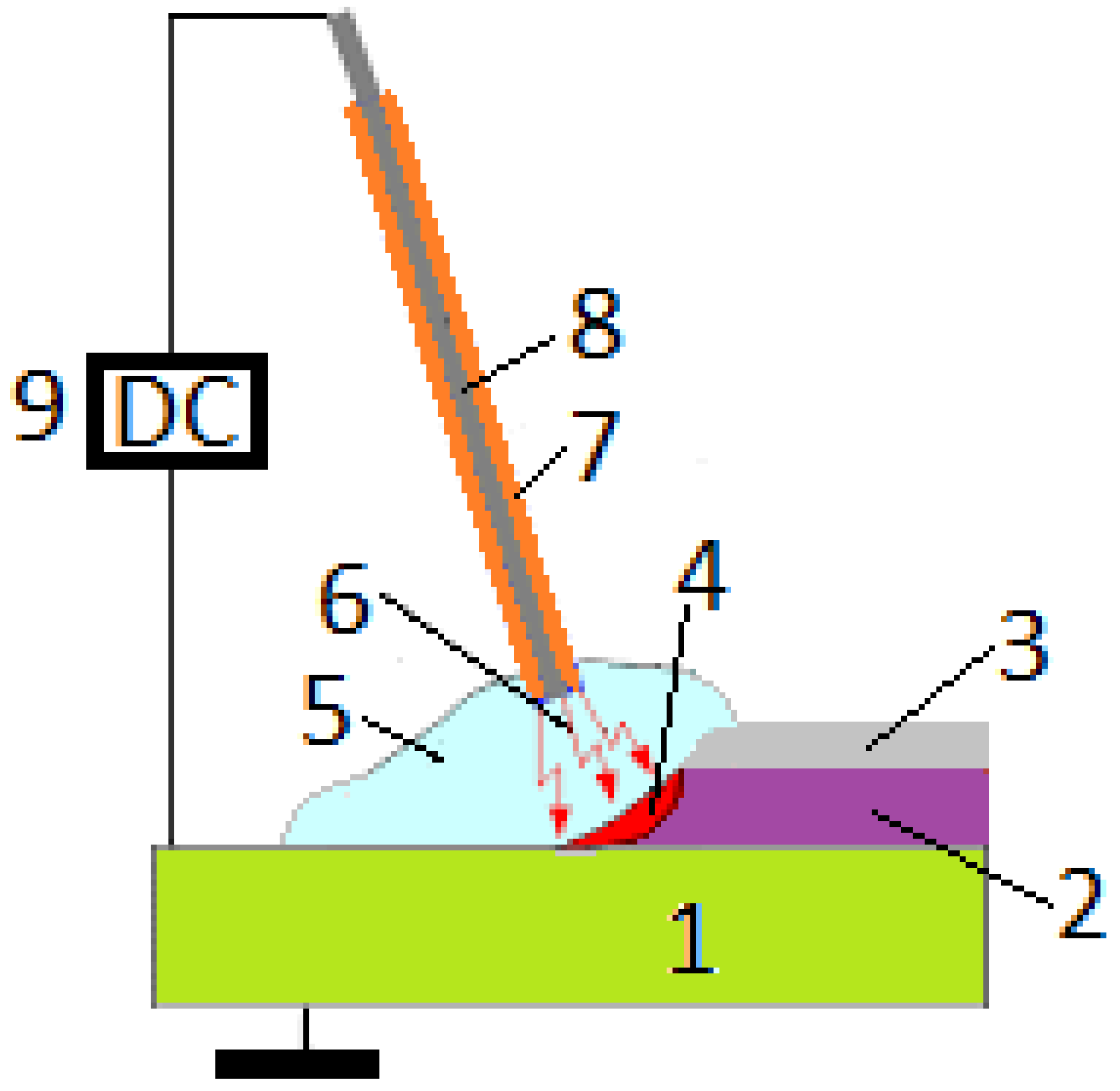
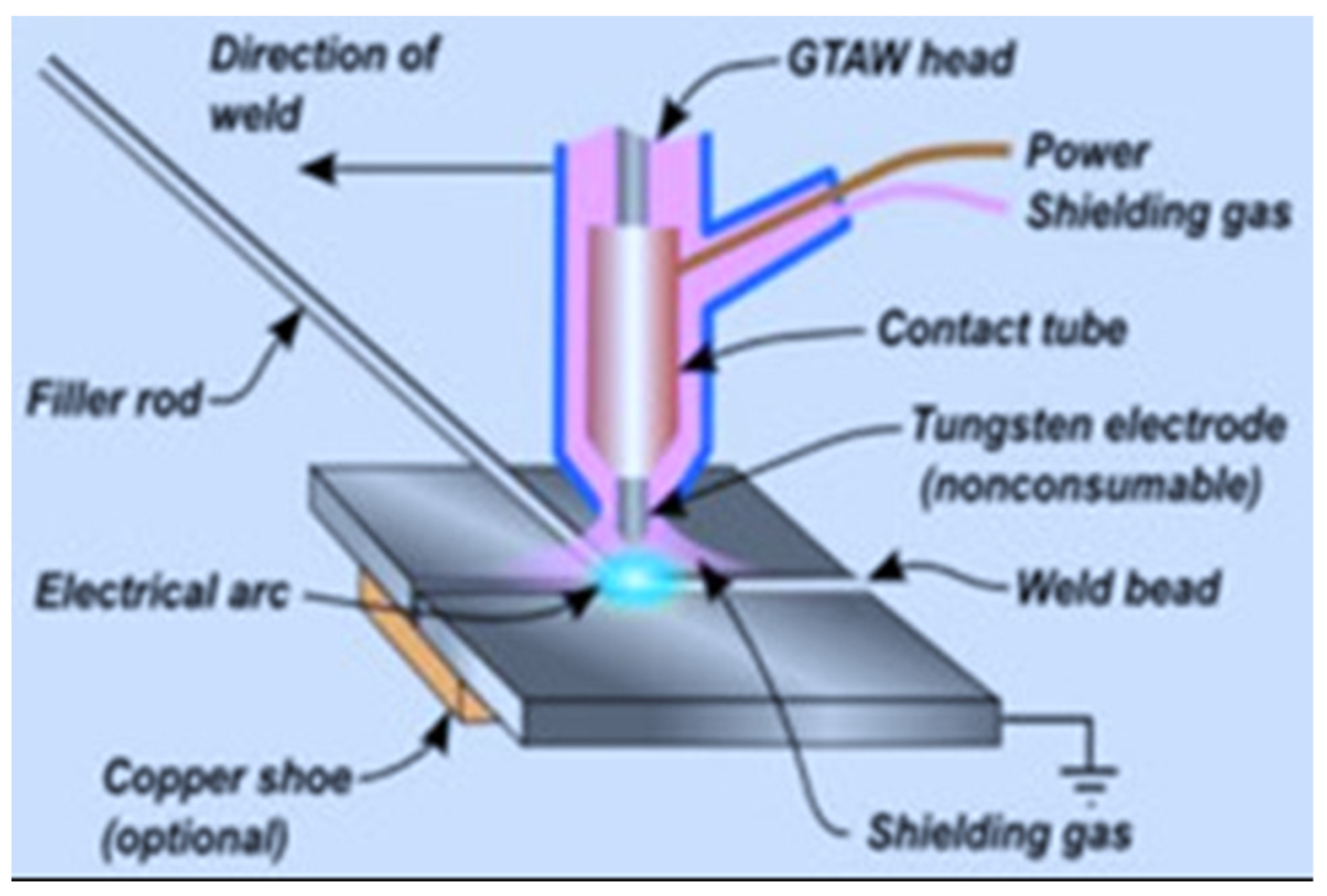


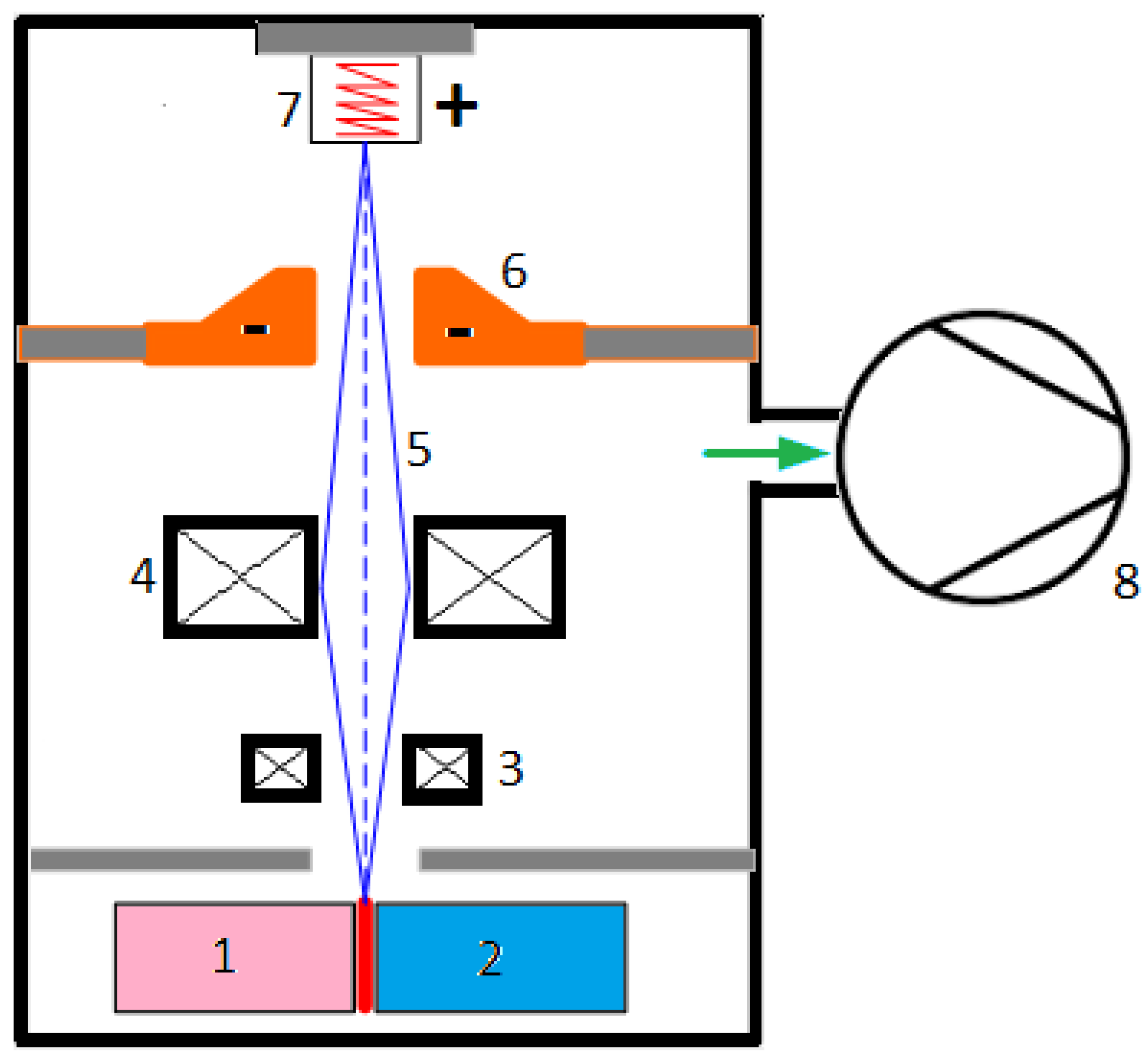
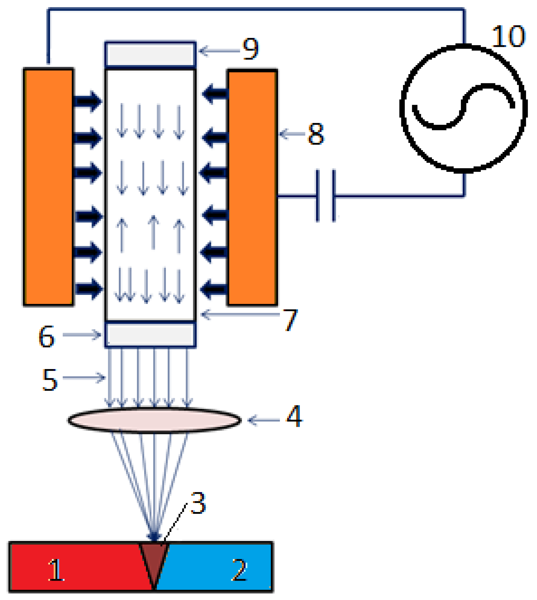
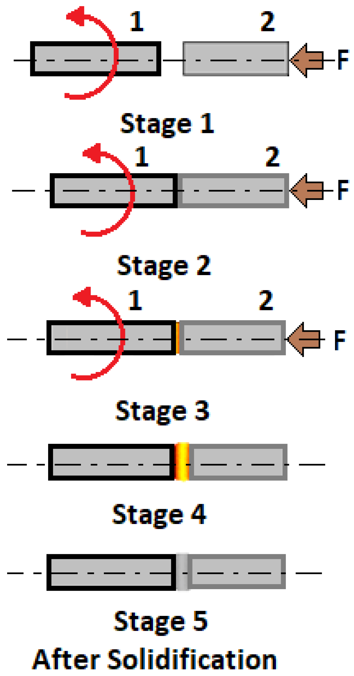


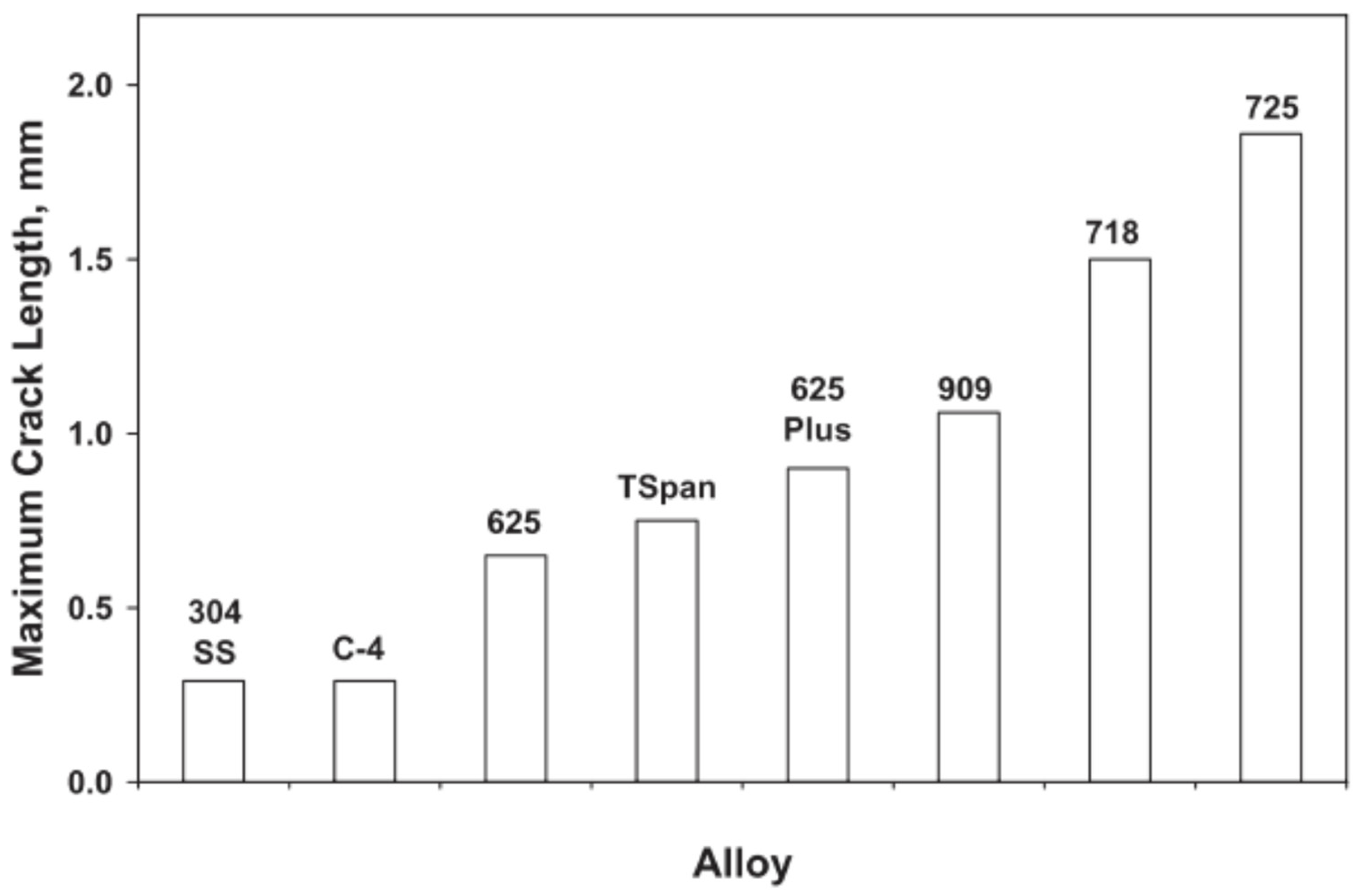

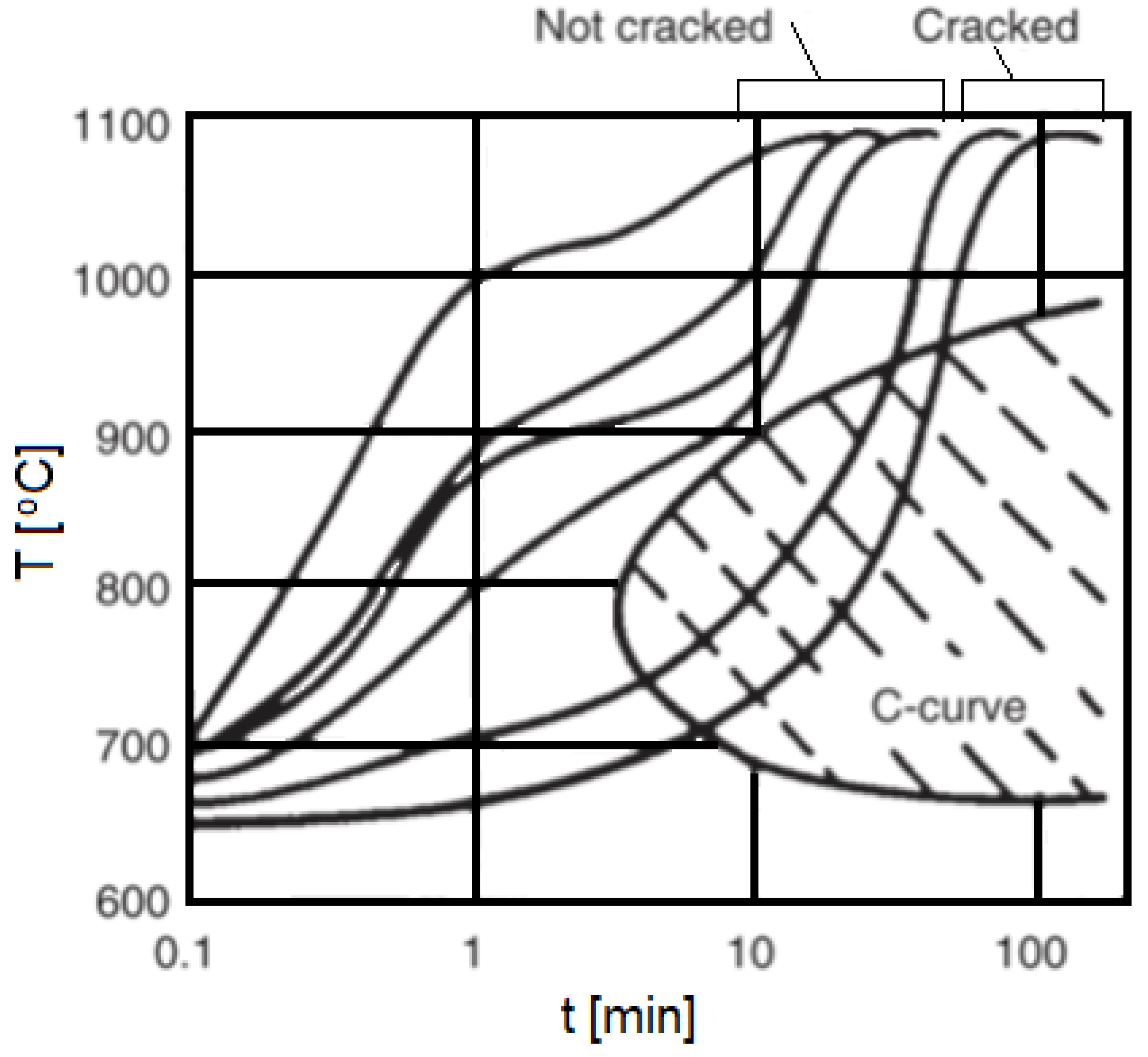

| Feature | Unit | Value | Refs. |
|---|---|---|---|
| Density at 20 °C | kg/m3 | 8902 | [6] |
| Melting temperature | °C | 1453 | [6] |
| Boiling temperature | °C | 2730 | [7] |
| Curie point | °C | 354 | [6] |
| Ionization energy | eV | 7.64 | [8] |
| Coefficient of thermal expansion at 20 °C | μm/(m·°C) | 13 | [6] |
| Electrical resistivity at 20 °C | μΩ·cm | 8 | [6] |
| Thermal conductivity at 20 °C | W/(m·K) | 69 | [6] |
| Specific heat at 20 °C | J/(kg K) | 470 | [6] |
| Feature | Unit | Value | Refs. |
|---|---|---|---|
| Modulus of elasticity in tension | [GPa] | 207 | [9] |
| Tensile Strength, | [MPa] | 317 * | [9] |
| Yield strength, 0.2% offset | [MPa] | 59 * | [9] |
| Elongation in 51 mm | [%] | 30 * | [9] |
| Hardness HB | [MPa] | 800–3000 | [10] |
| Hardness HV | [HV] | 124 | [11] |
| Poisson Number | [-] | 0.305–0.315 | [10] |
| Type of Metal and Its Alloys | Ni and Ni-Based Alloys | |||
|---|---|---|---|---|
| Group | CP Metal | SSS | PS | Special alloys |
| Alloys Compositions | Ni | Ni-Cu | Ni-Al-Ti | Ni-Al Intermetallic |
| Ni-Mo | Ni-Cu-Al-Ti | |||
| Ni-Fe | Ni-Cr-Al-Ti | |||
| Ni-Cr-Fe | Ni-Cr-Nb | Oxide Dispersion Strengthened | ||
| Ni-Cr-Mo-W | ||||
| Ni-Fe-Cr-Mo | Ni-Fe-Cr-Nb-Al-Ti | |||
| Ni-Cr-Co-Mo | ||||
| Components | Cu | Al | Fe | Mn | Ti | Ni |
|---|---|---|---|---|---|---|
| Alloy Designation | [%] | |||||
| 200 | <0.25 | - | <0.40 | <0.35 | - | >99.0 |
| 270 | 0.001 | - | 0.003 | 0.001 | - | >99.9 |
| 301 | <0.25 | 4.0–4.75 | <0.6 | <0.5 | 0.25–1.0 | balance |
| Property | Alloy Designation | 200 | 270 | 301 | Refs. |
|---|---|---|---|---|---|
| Unit | Value | ||||
| Density | [kg/m3] | 8.89·103 | 8.89·103 | 8.26·103 | [12] |
| Modulus of elasticity | [GPa] | 207 | 207 | 207 | [12] |
| Thermal expansion (20 °C) | [°C−1] | 13.3·10−6 | 13.3·10−6 | 12.9·10−6 | [12] |
| Specific heat capacity | [J/(kg·K)] | 456 | 460 | 435 | [12] |
| Thermal conductivity | [W/(m·K)] | 70.2 | 86 | 40.4 | [12] |
| Electric resistivity | [Ohm·m] | 9.5·10−8 | 7.5·10−8 | 42.4·10−8 | [12] |
| Tensile strength (annealed) | [MPa] | 462 | 345 | 462 | [12] |
| Tensile strength | [MPa] | 485 | - | - | [3] |
| Yield strength (annealed) | [MPa] | 148 | 110 | 148 | [12] |
| Yield strength | [MPa] | 275 | [3] | ||
| Elongation (annealed) | [%] | 45 | 50 | 45 | [12] |
| Elongation | [%] | 40 | - | - | [3] |
| Hardness | [RB] | 70 | - | - | [3] |
| Liquidus temperature | [°C] | 1446 | 1454 | - | [12] |
| Solidus temperature | [°C] | 1436 | 1454 | - | [12] |
| Solution temperature | [°C] | - | - | 925 | [12] |
| Aging temperature | [°C] | - | - | 588 | [12] |
| Property | Temperature | 93 | 204 | 260 | 316 | 371 | 427 | 482 | 538 | 593 | 649 | Refs. |
|---|---|---|---|---|---|---|---|---|---|---|---|---|
| Unit | Value | |||||||||||
| Yield strength | [MPa] | 102 | 101 | 105 | 97 | 93 | 89 | 83 | 77 | 70 | [12] | |
| Tensile strength | [MPa] | 372 | 372 | 362 | 325 | 284 | 269 | 228 | 186 | 153 | [12] | |
| Elongation | [%] | 44 | 41 | 42 | 53 | 58 | 58 | 60 | 72 | 74 | [12] | |
| Coefficient of thermal expansion, from 20 °C to | [μm/m⋅K] | 13.3 | 13.9 | 14.4 | ||||||||
| Electrical resistivity | [nΩ·m] | 126 | 188 | 273 | ||||||||
| Thermal conductivity | [W/m·K] | 67.1 | 61.3 | 56.3 | ||||||||
| Property | Tensile Strength | Yield Strength | Elongation | Hardness |
|---|---|---|---|---|
| Alloy Designation | [MPa] | [MPa] | [%] | [RB] |
| 400 | 585 | 345 | 35 | 75 |
| 600 | 550 | 345 | 40 | 90 |
| 601 | 620 | 380 | 40 | 95 |
| 617 | 795 | 450 | 40 | 98 |
| C-22 | 690 | 380 | 35 | 97 |
| 625 | 830 | 415 | 30 | 95 |
| 690 | 620 | 380 | 40 | 95 |
| 800 | 585 | 310 | 40 | 85 |
| 800H | 585 | 275 | 45 | 80 |
| 800HT | 585 | 275 | 40 | 80 |
| 825 | 655 | 345 | 35 | 90 |
| Component | Cu | Al | Ti | Fe | Mn | Si | Ni |
|---|---|---|---|---|---|---|---|
| Alloy Designation | [%] | ||||||
| Monel 400 | 28–34 | - | - | <2.5 | <2.0 | - | >63 |
| Monel 405 | 28–34 | - | - | <2.5 | <2.0 | <0.5 | >63 |
| Monel K-500 | 27–33 | 2.3–3.15 | 0.35–0.85 | <2.0 | <1.5 | - | >63 |
| Property | Alloy Designation | Monel 400 | Monel 405 | Monel K-500 |
|---|---|---|---|---|
| Unit | Value | |||
| Density | [kg/m3] | 8.80·103 | 8.80·103 | 8.44·103 |
| Modulus of elasticity | [GPa] | 179 | 179 | 179 |
| Thermal expansion (20 °C) | [°C−1] | 13.9·10−6 | 13.7·10−6 | 13.7·10−6 |
| Specific heat capacity | [J/(kg·K)] | 427 | 427 | 419 |
| Thermal conductivity | [W/(m·K)] | 21.8 | 21.8 | 17.5 |
| Electric resistivity | [Ohm·m] | 54.7·10−8 | 51·10−8 | 61.5·10−8 |
| Tensile strength (annealed) | [MPa] | 550 | 550 | 1100 pc |
| Yield strength (annealed) | [MPa] | 240 | 240 | 630 pc |
| Elongation (annealed) | [%] | 48 | 40 | 25 pc |
| Liquidus temperature | [°C] | 1350 | 1350 | 1350 |
| Solidus temperature | [°C] | 1300 | 1300 | 1300 |
| Alloy Type | Property | Temperature [°C] | 100 | 200 | 300 | 400 | 500 | 600 | 700 | 800 | 900 | 1000 | 1150 | Refs. |
|---|---|---|---|---|---|---|---|---|---|---|---|---|---|---|
| Unit | Value | |||||||||||||
| 400 | Yield strength | [MPa] | >150 | >135 | >130 | >130 (425 °C) | [17] | |||||||
| K500 | 670 | 640 | 620 | 600 | 570 | 490 | [18] | |||||||
| 400 | Tensile strength | [MPa] | >420 | >390 | >380 | >370 (425 °C) | [17] | |||||||
| K500 | 1040 | 1020 | 980 | 890 | 750 | 620 | [18] | |||||||
| 400 | Coefficient of thermal expansion, from 20 °C to | [μm/m⋅K] | 13.8 | 14.5 | 14.9 | 15.2 | 15.6 | 16.0 | 16.4 | 16.8 | 17.3 | [17] | ||
| K500 | 13.7 | 14.6 | 14.9 | 15.2 | 15.5 | 16.0 | 16.6 | 17.0 | 17.5 | [18] | ||||
| 400 | Electrical resistivity | [nΩ·m] | 540 | 555 | 575 | 585 | 600 | 618 | 635 | 655 | 675 | [17] | ||
| K500 | 6200 | 6300 | 6500 | 6500 | 6500 | 6600 | 6600 | 6700 | 6800 | [18] | ||||
| 400 | Thermal conductivity | [W/m·K] | 25.4 | 28.7 | 31.9 | 34.7 | 38.4 | 41.2 | 43.1 | 45.1 | 47.5 | 50 | 52.9 | [17] |
| K500 | 19.4 | 20.9 | 25.1 | 27.8 | 30.5 | 33.1 | 35.7 | 37.4 | 41.2 | [18] | ||||
| 400 | Specific heat capacity | [J/kg·K] | 461 | 473 | 484 | 495 | 523 | 544 | 555 | 566 | 577 | 587 | 603 | [17] |
| K500 | 545 | 480 | 491 | 500 | 517 | 538 | 567 | 613 | 685 | [18] | ||||
| 400 | Young modulus | [GPa] | 180 | 177 | 170 | 165 | 150 | [17] | ||||||
| K500 | 178 | 176 | 173 | 168 | 164 | 162 | 158 | [18] | ||||||
| Property | Tensile Strength | Yield Strength | Elongation | Hardness | Rupture Stress (1000 h Exposure) MPa | ||
|---|---|---|---|---|---|---|---|
| Alloy | MPa | MPa | % | HRC | 650 °C | 760 °C | 870 °C |
| K500 | 1100 | 790 | 20 | - | - | - | - |
| X-750 | 1100–1380 | 690–1035 | 15–30 | 35–40 | 540 | 275 | 55 |
| 80A | 970–1240 | 585–830 | 25–36 | - | 520 | 220 | - |
| 90 | 1100–1310 | 760–860 | 17–30 | - | - | 240 | 75 |
| 263 | 970–1100 | 585–690 | 35–45 | - | 400 | 170 | 40 |
| 282 | 1165 | 720 | 32 | 32 | 550 | 240 | 70 |
| 713 | 830 | - | 5 | 35–45 | - | - | - |
| 718 | 1035–1590 | 900–1240 | 14–30 | 30–40 | 580 | 195 | - |
| Waspaloy | 1345 | 900 | 26 | 34–45 | 460 | 195 | 50 |
| Rene 41 | 1345 | 1070 | 15 | 33–40 | 580 | 235 | 60 |
| 725 | 1165–1310 | 830–970 | 25–35 | 30–40 | - | - | - |
| 706 | 1240–1380 | 970–1100 | 15–25 | 30–40 | 550 | 170 | - |
| 909 | 1275 | 1035 | 15 | - | 325 | - | - |
| 925 | 970 | 760 | 18 | 26–38 | - | - | - |
| 945 | 1100–1240 | 900–1035 | 20–30 | 40–45 | - | - | - |
| Components | Ni | Fe | Cr | Mo | W | Al | Co | Cu | Zr | Mn | Ti | Si | Nb | Refs. |
|---|---|---|---|---|---|---|---|---|---|---|---|---|---|---|
| Alloy | [%] | |||||||||||||
| K-500 | 63–70 | 2 | - | - | - | 2.3–3.15 | - | Bal. | - | 1.5 | 0.35–0.85 | 0.5 | - | [61] |
| Nimonic 80A | Bal. | <3.0 | 18–21 | - | - | 1–1.8 | <2.0 | <0.2 | - | <1 | 1.8–2.7 | <1 | - | [62] |
| Nimonic 90 | Bal. | <1.5 | 18–21 | - | - | 1–2 | 15.0–21.0 | <0.2 | - | <1 | 2–3 | <1 | - | [47] |
| Nimonic C-263 | Bal. | <0.7 | 19–21 | 5.6–6.1 | - | <0.6 | 19.0–21.0 | <0.2 | - | <0.6 | 1.9–2.4 | <0.4 | - | [63] |
| Haynes 282 | Bal. | 1.5 | 18.5–20.5 | 8–9 | 0.5 | 1.38–1.65 | 9–11 | 0.1 | - | 0.3 | 1.9–2.3 | 0.15 | 0.2 | [64] |
| Inconel 713 | Bal. | <2.5 | 12–14 | 3.8–5.2 | - | 5.5–6.5 | 1.8–2.8 | <0.5 | <0.15 | 0.25 | - | - | <2.5 | [65] |
| Inconel 718 | 50–55 | Bal. | 17–21 | 2.8–3.3 | - | 0.2–0.8 | <1.0 | <0.3 | - | <0.35 | 0.65–1.15 | - | 4.75–5.5 | [32] |
| Waspaloy | Bal. | <2 | 19 | 4.3 | - | 1.5 | 13.5 | <0.1 | 0.05 | <0.1 | 3 | <0.15 | - | [66] |
| Rene 41 | Bal. | <5 | 18–20 | 9–10.5 | - | 1.4–1.8 | 10–12 | - | - | <0.1 | 3.0–3.3 | <0.5 | - | [67] |
| Inconel 725 | 55.0–59.0 | Bal. | 19–22.5 | 7–9.5 | - | <0.35 | - | - | - | <0.35 | 1–1.7 | <0.2 | 2.75–4 | [68] |
| Inconel 706 | 39–44 | Bal. | 14.5–17.5 | - | - | <0.4 | <1 | <0.3 | - | <0.35 | 1.5–2 | <0.35 | 2.5–3.3 | [69] |
| Incoloy 909 | 35–40 | Bal. | - | - | - | <0.15 | 12–16 | - | - | - | 1.3–1.8 | 0.25–0.5 | 4.3–5.2 | [70] |
| Incoloy 945 | 45–55 | Bal. | 19.5–23 | 3–4 | - | <0.7 | - | 1.5–3 | - | <1 | 0.5–2.5 | <0.5 | 2.5–4.5 | [71] |
| Property | Temperature [°C] | 100 | 200 | 300 | 400 | 500 | 600 | 700 | 800 | 900 |
|---|---|---|---|---|---|---|---|---|---|---|
| Unit | Values | |||||||||
| Yield Strength | MPa | 670 | 640 | 620 | 600 | 570 | 490 | - | - | - |
| Tensile Strength | MPa | 1040 | 1020 | 980 | 890 | 750 | 620 | - | - | - |
| Coefficient of thermal expansion, from 20 °C to | [μm/m⋅K] | 13.7 | 14.6 | 14.9 | 15.2 | 15.5 | 16 | 16.6 | 17 | 17.5 |
| Electrical resistivity | [nΩ·m] | 6200 | 6300 | 6500 | 6500 | 6500 | 6600 | 6600 | 6700 | 6800 |
| Thermal conductivity | [W/m·K] | 19.4 | 20.9 | 25.1 | 27.8 | 30.5 | 33.1 | 35.7 | 37.4 | 41.2 |
| Specific heat capacity | [J/kg·K] | 545 | 480 | 491 | 500 | 517 | 538 | 567 | 613 | 685 |
| Modulus of elasticity | [GPa] | 178 | 176 | 173 | 168 | 164 | 162 | 158 | - | - |
| Component | Mo | Cr | Ni | Fe | Mn | Co | W | Refs. |
|---|---|---|---|---|---|---|---|---|
| Alloy Designation | [%] | |||||||
| B2 | 26–30 | <1 | Rest | <2 | <1 | <1 | - | [20] |
| B3 | 27–32 | 1–3 | >65 | 1–3 | <3 | <3 | <3 | [21] |
| Property | Alloy Designation | B2 | B3 |
|---|---|---|---|
| Unit | Value | ||
| Density ρ | [g/cm3] | 9.2 | 9.22 |
| Resistivity at 20 °C | [Ω mm2/m] | 1.37 | 1.37 |
| Linear thermal expansion coefficient α | [×10−6/K] | 10.3 | 10.6 |
| Thermal conductivity λ at 50 °C | [W/m K] | 11.4 | |
| Specific heat capacity at 20 °C | [kJ/kg K] | 373–377 | |
| Melting point (approx.) | [°C] | 1300–1350 | 1370–1418 |
| Tensile strength | [MPa] | 760 | 750 |
| Yield point | [MPa] | 350 | 340 |
| Elongation at rupture | [%] | 40 | 40 |
| Young Modulus | [GPa] | 217 | 216 |
| Hardness | [HB] | 240 | 240 |
| Refs. | [20,22] | [23] | |
| Alloy Type | Property | Temperature [°C] | 100 | 200 | 300 | 400 | 500 | 600 | 800 | Refs. |
|---|---|---|---|---|---|---|---|---|---|---|
| Unit | Value | |||||||||
| B2 sheets and plates, 1.3 to 3.0 mm thick, solutioned and quenched | Yield strength | [MPa] | 450 | 425 | 415 | [22] | ||||
| B2 sheets and plates, 2.5 to 9.0 mm thick, solutioned and quenched | 350 | 325 | 310 | [22] | ||||||
| B2 plates, 9 to 50 mm thick, solutioned and quenched | 360 | 340 | 315 | [22] | ||||||
| B3 3.2 mm thick sheets, bright annealed | 380 | 325 | 300 (315 °C) | 290 (425 °C) | 270 (540 °C) | 315 (650 °C) | [23] | |||
| B3 6.4 mm thick plates, solution treated | 375 | 330 | 305 (315 °C) | 285 (425 °C) | 275 (540 °C) | 290 (650 °C) | [23] | |||
| B2 sheets and plates, 1.3 to 3.0 mm thick, solutioned and quenched | Tensile strength | [MPa] | 885 | 860 | 860 | [22] | ||||
| B2 sheets and plates, 2.5 to 9.0 mm thick, solutioned and quenched | 850 | 820 | 805 | [22] | ||||||
| B2 plates, 9 to 50 mm thick, solutioned and quenched | 870 | 840 | 820 | [22] | ||||||
| B3 3.2 mm thick sheets, bright annealed | 830 | 760 | 720 (315 °C) | 705 (425 °C) | 675 (540 °C) | 715 (650 °C) | [23] | |||
| B3 6.4 mm thick plates, solution treated | 845 | 795 | 765 (315 °C) | 745 (425 °C) | 730 (540 °C) | 735 (650 °C) | [23] | |||
| B2 sheets and plates, 1.3 to 3.0 mm thick, solutioned and quenched | Elongation | [%] | 50 | 49 | 51 | [22] | ||||
| B2 sheets and plates, 2.5 to 9.0 mm thick, solutioned and quenched | 59 | 60 | 60 | [22] | ||||||
| B2 plates, 9 to 50 mm thick, solutioned and quenched | 60 | 60 | 61 | [22] | ||||||
| B3 3.2 mm thick sheets, bright annealed | 56.9 | 59.7 | 63.4 (315 °C) | 62.0 (425 °C) | 59.0 (540 °C) | 55.8 (650 °C) | [23] | |||
| B3 6.4 mm thick plates, solution treated | 58.2 | 60.9 | 61.6 (315 °C) | 61.7 (425 °C) | 61.7 (540 °C) | 64.6 (650 °C) | [23] | |||
| B2 | Coefficient of thermal expansion, from 20 °C to | [μm/m·K] | 10.3 (93 °C) | 10.8 (204 °C) | 11.2 (316 °C) | 11.5 (427 °C) | 11.7 (538 °C) | [22] | ||
| Electrical resistivity | [nΩ·m] | 1380 | 1380 | 1390 | 1390 | 1410 | 1460 | [22] | ||
| Thermal conductivity | [W/m·K] | 12.2 | 13.4 | 14.6 | 16.0 | 17.3 | 18.7 | [22] | ||
| Thermal diffusivity | [mm2/s] | 3.4 | 3.6 | 3.8 | 4.0 | 4.2 | 4.5 | [22] | ||
| Specific heat capacity | [J/kg·K] | 406 | 431 | 456 | [22] | |||||
| Dynamic modulus of elasticity | [GPa] | 202 (315 °C) | 196 (425 °C) | 189 (540 °C) | [22] | |||||
| Component | Ni | Fe | Refs. |
|---|---|---|---|
| Alloy Designation | [%] | ||
| Nifethal® 70 | 72 | Bal. | [28] |
| Nifethal® 52 | 52 | Bal. | [28] |
| Invar K93600 | 36 | 64 | [29] |
| Property | Alloy Designation | Nifethal 70 | Nifethal 52 | Invar K93600 |
|---|---|---|---|---|
| Unit | Value | |||
| Max operating temperature | [°C] | 600 | 600 | 260 |
| Density ρ | [g/cm3] | 8.45 | 8.20 | 8.13 |
| Resistivity at 20 °C | [Ω mm2/m] | 0.20 | 0.376 | 0.75 |
| Temperature factor of the resistivity, Ct | ||||
| 250 °C | [-] | 2.19 | 1.93 | - |
| 500 °C | [-] | 3.66 | 2.77 | - |
| Linear thermal expansion coefficient α | ||||
| 20–100 °C | [×10−6/K] | - | 10 | 1 |
| 20–500 °C | [×10−6/K] | 13 | - | - |
| 20–1000 °C | [×10−6/K] | 15 | - | - |
| Thermal conductivity λ at 50 °C | [W/m K] | 17 | 17 | 10.5 |
| Specific heat capacity at 20 °C | [kJ/kg K] | 0.52 | 0.52 | 0.515 |
| Melting point (approx.) | [°C] | 1430 | 1435 | - |
| Tensile strength | [MPa] | 640 | 610 | 490 |
| Yield strength | [MPa] | - | 340 | 310 |
| Elongation at rupture | [%] | - | 30 | 30 |
| Young Modulus | [GPa] | - | - | 140 |
| Magnetic properties (Curie point) | [°C] | 610 | 530 | - |
| Emissivity, fully oxidized condition | [-] | 0.88 | 0.88 | - |
| Hardness | [HB] | 140 | ||
| Refs. | [28] | [28] | [20] | |
| Component | Ni | Fe | Cr | Mo | W | Cu |
|---|---|---|---|---|---|---|
| Alloy Designation | [%] | |||||
| 800 | 32 | 45 | 21 | 9 | 3.5 | - |
| 800H | 32 | bal. | 20 | - | - | - |
| 825 | 42 | 25 | 21 | 3 | - | 2 |
| G3 | bal. | 20 | 22 | 7 | - | 2 |
| Component | Ni | Cr | Mn | Si | Corrosion | Melting Range | Young’s Modulus |
|---|---|---|---|---|---|---|---|
| Type of Steel | % | Mpy (a) | °C | MPa | |||
| 201 | 3.5–5.5 | 16–18 | 5.5–7.5 | <1 | 20 | 1398–1454 | 193,053 |
| 301 | 6.0–8.0 | 16–18 | <2.0 | <1 | 12 | 1398–1421 | 193,053 |
| 302 | 8.0–10.0 | 17–19 | <2.0 | <1 | 10–18 | 1398–1421 | 193,053 |
| 304 | 8.0–10.5 | 18–20 | <2.0 | <1 | 6–12 | 1398–1454 | 193,053 |
| 309 | 19.0–22.0 | 24–26 | <2.0 | <1 | 5–9 | 1398–1454 | 199,947 |
| Component | Ni | Cr | Mn | Fe | Cu | Al | Ti | Co | Nb | Mo | V | Refs. |
|---|---|---|---|---|---|---|---|---|---|---|---|---|
| Type | [%] | |||||||||||
| 600 | >72 | 14–17 | <1 | 6–10 | <0.5 | 0 | 0 | 0 | 0 | - | - | [32] |
| 601 | 58–63 | 21–25 | <1 | Bal. | <1 | 1.0–1.7 | 0 | - | - | - | - | [32] |
| 625 | >58 | 20–23 | <0.5 | <5 | - | <0.4 | <0.4 | <1 | 3.15–4.15 | 8–10 | - | [32] |
| 718 | 50–55 | 17–21 | <0.35 | Bal. | <0.3 | 0.2–0.8 | 0.65–1.15 | <1 | 4.75–5.5 | 2.8–3.3 | - | [32] |
| 800 | 32.5 | 21 | <0.8 | 46 | 0.4 | 0.4 | 0.4 | - | - | - | - | [32] |
| G3 | bal. | 21–23.5 | <1 | 18–21 | 1.5–2.5 | <5 | 6-8 | <1.5 | [33] | |||
| Type | Yield Strength at 21 °C | Melting Range | Rupture Strength; 100 h at (°C, MPa) | |
|---|---|---|---|---|
| MPa | °C | °C | MPa | |
| 600 | 285 | 1355–1415 | 871 | 37 |
| 601 | 338 | 1355–1415 | 871 | 48 |
| 625 | 490 | 1260–1335 | 871 | 72 |
| 718 | 1186 | 1260–1335 | 649 | 689 |
| 800 | 250 | 1355–1385 | 982 | 145 |
| Property | Unit | State | 600 | 601 | 625 | 718 | 800 | G3 |
|---|---|---|---|---|---|---|---|---|
| Density | g/cm3 | - | 8.42 | 8.1 | 8.44 | 8.19 | 7.94 | 8.14 |
| Melting Range | °C | - | 1354–1413 | - | - | 1260–1360 | 1357–1385 | 1260–1343 |
| Specific Heat | J/kg-K | - | 444 | 450 | 410 | 435 | 502 | 453 |
| Thermal conductivity | W/m·K | - | - | 11.3 | 9.8 | 11.4 | 13 | 10 |
| Linear expansion coefficient | μm/m·K | - | 14.4–17.7 | - | 13–16 | 16.8–18 | 14.6–15.1 | |
| Electrical resistivity | μΩ·m | - | 1.03 | 1.19 | 1.29 | 1.22 | 0.989 | 1.12 |
| Curie temperature | °C | - | −124 | - | <126 | −112 | −115 | - |
| Young Modulus | GPa | - | 190 | 206.5 | 207 | 200 | 193 | 199 |
| Hardness | HRB | Cold-drawn and annealed | 65–85 | <220 | 190 | 32–40HRC | 138 | - |
| Hot-finished | 75–95 | - | - | 16HRC | - | - | ||
| Tensile Strength | MPa | Cold-drawn and annealed | 550–690 | 550–750 | 855 | 1034–1240 | 517–827 (1034) | 621–896 |
| Hot-finished | 585–830 | 741 | - | 896 | 552–827 | - | ||
| Yield Strength | MPa | Cold-drawn and annealed | 170–345 | >205 | 490 | 827–1189 | 207–448 (862) | 241–862 |
| Hot-finished | 240–620 | 290 | - | 448 | 172–448 (621) | - | ||
| Elongation | % | Cold-drawn and annealed | 55–35 | >30 | 50 | 12–22 | 60–25 | 45–13 |
| Hot-finished | 50–30 | 47 | 54 | 50–25 | - | |||
| Refs. | [34] | [35] | [36] | [37] | [38] | [33] |
| Alloy Type | Property | Temperature [°C] | 100 | 200 | 300 | 400 | 500 | 600 | 700 | 800 | 900 | 1000 | Refs. |
|---|---|---|---|---|---|---|---|---|---|---|---|---|---|
| Unit | Value | ||||||||||||
| 601 | Yield strength | [MPa] | 221 | 203 | [35] | ||||||||
| 625 | 405 (538 °C) | 420 (649 °C) | 420 (760 °C) | 375 (871 °C) | [36] | ||||||||
| 718 | 1207 | 1138 | 1104 | 1090 | 1069 | 1055 | 897 | [37] | |||||
| 601 | Tensile strength | [MPa] | 674 | 640 | [35] | ||||||||
| 625 | 745 (538 °C) | 710 (649 °C) | 505 (760 °C) | 285 (871 °C) | [36] | ||||||||
| 718 | 1379 | 1345 | 1338 | 1324 | 1276 | 1242 | 904 | [37] | |||||
| 601 | Elongation | [%] | 46 | 45 | [35] | ||||||||
| 625 | 50 (538 °C) | 35 (649 °C) | 42 (760 °C) | 125 (871 °C) | [36] | ||||||||
| 601 | Coefficient of thermal expansion, from 20 °C to | [μm/m·K] | 13.75 | 14.36 | 14.58 | 14.83 | 15.19 | 15.62 | 16.11 | 16.67 | 17.24 | 17.82 | [35] |
| 625 | 14.0 (24–540 °C) | 15.8 (24–870 °C) | [36] | ||||||||||
| 718 | 13.2 | 13.6 (205 °C) | 13.9 (315 °C) | 14.3 (425 °C) | 14.6 (540 °C) | 15.1 (650 °C) | 16.0 (760 °C) | [37] | |||||
| 800 | 16.8 (26–500 °C) | 17.1 (26–600 °C) | 17.5 (26–700 °C) | 18.0 (26–800 °C) | [38] | ||||||||
| G3 | 14.3 | 14.7 | 15.0 | 15.3 | 15.7 | 16.1 | 16.5 | [39] | |||||
| 601 | Electrical resistivity | [nΩ·m] | 1207 | 1229 | 1247 | 1249 | 1259 | 1262 | [35] | ||||
| 800 | 989 | 1035 | 1089 | 1127 | 1157 | 1191 | 1223 | 1266 | 1283 | 1291 | [38] | ||
| G3 | 1170 | 1190 | 1210 | 1230 | 1250 | 1260 | 1270 | [39] | |||||
| 601 | Thermal conductivity | [W/m·K] | 14.3 | 17.7 | 21.0 | 24.4 | 26.1 | 27.8 | [35] | ||||
| 625 | 17.5 (540 °C) | 22.8 (870 °C) | [36] | ||||||||||
| 800 | 13.0 | 14.7 | 16.3 | 17.9 | 19.5 | 21.1 | 22.8 | 21.1 | 31.9 | [38] | |||
| G3 | 12.6 | 14.3 | 16.0 | 17.7 | 19.3 | 21.0 | 22.6 | [39] | |||||
| 601 | Specific heat capacity | [J/kg·K] | 498 | 548 | 603 | 657 | 686 | 712 | [35] | ||||
| G3 | 452 | 462 | 471 | 479 | 487 | 495 | 503 | [39] | |||||
| 601 | Dynamic modulus of elasticity | [GPa] | 196.8 | 184.8 | 170.8 | 150.2 | 137.9 | 124.7 | [35] | ||||
| 718 | 193 (150 °C) | 190 (205 °C) | 184 (315 °C) | 178 (425 °C) | 171 (540 °C) | 163 (650 °C) | 159 (705 °C) | 147 (815 °C) | 130 (925 °C) | 110 (1040 °C) | [37] | ||
| 800 | 191.3 | 184.8 | 178.3 | 171.6 | 165 | 157.7 | 150.1 | 141.3 | [38] | ||||
| G3 | 205 | 199 | 192 | 186 | 180 | 173 | 167 | [39] | |||||
| Components | Ni | Fe | Cr | Co | Mo | Cu | W | V | Ti | Al | Mn | Refs. |
|---|---|---|---|---|---|---|---|---|---|---|---|---|
| Alloy Designation | [%] | |||||||||||
| Incoloy 825 | 38–46 | balance | 19.5–23.5 | - | 2.5–3.5 | 1.5–3 | - | - | 0.6–1.2 | - | <1 | [43] |
| Incoloy 925 | 42–46 | >22 | 19.5–22.5 | - | 2.5–3.5 | 1.5–3 | - | - | 1.9–2.4 | - | <1 | [44] |
| Incoloy 926 | 46 | - | 22.5 | - | 3.5 | 3 | - | - | 2.4 | - | 1 | [45] |
| Incoloy 800, 800H, 800HT | 30.0–35.0 | >39.5 | 19–23 | - | - | <0.75 | - | - | 0.15–0.60 | 0.15–0.60 | <1.5 | [38] |
| Nimonic 86 | Bal. | - | 25 | - | 10 | - | - | - | - | - | [46] | |
| Nimonic 90 | Bal. | <1.5 | 18–21 | 15–21 | - | <0.2 | - | - | 2–3 | 1–2 | <1 | [47] |
| Hastelloy C-276 | Bal. | 4–7 | 14.5–16.5 | <2.5 | 15–17 | 3–4.5 | <0.35 | - | - | <1 | [48] | |
| Hastelloy C-4 | 65 | <3 | 16 | <2 | 16 | -- | - | <0.7 | - | <1 | [49] | |
| Alloy Designation | Incoloy 825 | Incoloy 925 | Incoloy 926 | Incoloy 800 | Nimonic 86 | Nimonic 90 | Hastelloy C-276 | Hastelloy C-4 | |
|---|---|---|---|---|---|---|---|---|---|
| Property | Unit | ||||||||
| Density ρ | [g/cm3] | 8.14 | 8.08 | 8.1 | 7.94 | 8.45 | 8.18 | 8.9 | 8.64 |
| Resistivity at 20 °C | [Ω mm2/m] | 1.127 | 1.17 | - | 0.989 | - | 1.18 | 1.3 | 1.25 |
| Linear thermal expansion coefficient α, | [×10−6/K] | 14 | 13.2 | - | 16.8–18 | 12.7 | 12.7 | 11.2 | 10.8 |
| Thermal conductivity λ at 50 °C | [W/m K] | 11.1 | 12 | - | 13 | - | 11.47 | 9.8 | 10 |
| Specific heat capacity at 20 °C | [kJ/kg K] | 440 | 435 | 500 | 502 | - | 446 | 427 | 416 |
| Melting temperature | [°C] | 1370–1400 | 1311–1366 | 1320–1390 | 1357–1385 | - | 1310–1370 | 2415–2500 | - |
| Tensile strength | [MPa] | 690 | >965 | 600 | 517–827 (1034) | 873 | 1175–1265 | >690 | >690 |
| Yield point | [MPa] | 324 | >724 | 300 | 207–448 (862) | 438 | 752–831 | >283 | >280 |
| Elongation | [%] | 45 | >18 | 40 | 60–25 | 45 | 17–30 | 40 | >35 |
| Young Modulus | [GPa] | 195 | 199 | 193 | 210 | 204–220 | 205 | - | |
| Magnetic properties (Curie point) | [°C] | −196 | - | −30 | −115 | - | - | - | - |
| Hardness | [HB] | 90 | 26–38HRC | 86 | 138 | - | - | 90 | <240 HBW |
| Refs. | [43] | [44] | [45,50] | [38] | [46] | [47] | [48] | [49] | |
| Alloy Type | Property | Temperature [°C] | 100 | 200 | 300 | 400 | 500 | 600 | 700 | 800 | 900 | 1000 | Refs. |
|---|---|---|---|---|---|---|---|---|---|---|---|---|---|
| Unit | Value | ||||||||||||
| 825 | Yield strength | [MPa] | 279 (93 °C) | 245 (204 °C) | 232 (316 °C) | 228 (427 °C) | 229 (538 °C) | 213 (649 °C) | 183 (760 °C) | 117 (871 °C) | 47 (982 °C) | 23 (1093 °C) | [43] |
| 926 | > 230 | >190 | >170 | >160 | - | - | - | - | - | - | [51] | ||
| 86 | - | - | 251 | - | 243 | - | 239 | 173 (850 °C) | 125 | 44 (1050 °C) | [46] | ||
| 90 | >635 | >610 | >585 | >565 | >545 | >530 | >500 | >398 | - | - | [47] | ||
| 825 | Tensile strength | [MPa] | 655 (93 °C) | 637 (204 °C) | 632 (316 °C) | 610 (427 °C) | 592 (538 °C) | 465 (649 °C) | 274 (760 °C) | 135 (871 °C) | 75 (982 °C) | 42 (1093 °C) | [43] |
| 86 | - | - | 692 | - | 661 | - | 557 | 319 (850 °C) | 237 | 98 (1050 °C) | [46] | ||
| 825 | Elongation | [%] | - | - | - | - | 43 (538 °C) | 62 (649 °C) | 87 (760 °C) | 102 (871 °C) | - | - | [43] |
| 86 | - | - | 49 | - | 54 | - | 56 | 69 (850 °C) | 66 | 50 (1050 °C) | [46] | ||
| 825 | Coefficient of thermal expansion, from 20 °C to | [μm/m·K] | 14 (24–93 °C) | 14.9 (24–205 °C) | 15.3 (24–315 °C) | 15.7 (24–425 °C) | 15.8 (24–540 °C) | 16.4 (24–650 °C) | 17.1 (24–760 °C) | 17.5 (24–870 °C) | - | - | [43] |
| 925 | 13.2 | 14.2 | 14.7 | 15 | 15.3 | 15.7 | 16.3 | 17.2 | - | - | [44] | ||
| 926 | 15.8 | 16.1 | 16.5 | 16.9 | 17.3 | - | - | - | - | - | [51] | ||
| 800H | - | - | - | - | 16.8 (26–500 °C) | 17.1 (26–600 °C) | 17.5 (26–700 °C) | 18 (26–800 °C) | - | - | [38] | ||
| 800HT | - | - | - | - | 16.8 (26–500 °C) | 17.1 (26–600 °C) | 17.5 (26–700 °C) | 18 (26–800 °C) | - | - | [38] | ||
| 86 | 12.7 | 12.8 | 13.1 | 13.5 | 13.9 | 14.1 | - | 15.5 (850 °C) | - | 16.8 (1050 °C) | [46] | ||
| 90 | 12.7 | 13.3 | 13.7 | 14 | 14.3 | 14.8 | 15.3 | 16.2 | 17.1 | 18.2 | [47] | ||
| C276 | 11.2 (24–93 °C) | 12 (24–205 °C) | 12.8 (24–315 °C) | 13.2 (24–425 °C) | 13.4 (24–540 °C) | 14.1 (24–650 °C) | 14.9 (24–760 °C) | 15.9 (24–70 °C) | 16 (24–925 °C) | - | [48] | ||
| C4 | 10.8 (93 °C) | 11.9 (205 °C) | 12.6 (315 °C) | 13 (425 °C) | 13.3 (540 °C) | 13.5 (650 °C) | 14.4 (760 °C) | 14.9 (870 °C) | 15.7 (980 °C) | - | [49] | ||
| 825 | Electrical resistivity | [nΩ·m] | 1142 (93 °C) | 1180 (205 °C) | 1210 (315 °C) | 1248 (425 °C) | 1265 (540 °C) | 1267 (650 °C) | 1272 (760 °C) | 1288 (870 °C) | 1300 (980 °C) | - | [43] |
| 800H | 989 | 1035 | 1089 | 1127 | 1157 | 1191 | 1223 | 1266 | 1283 | 1291 | [38] | ||
| 800HT | 989 | 1035 | 1089 | 1127 | 1157 | 1191 | 1223 | 1266 | 1283 | 1291 | [38] | ||
| 90 | 1210 | 1230 | 1260 | 1280 | 1310 | 1310 | 1310 | 1310 | 1300 | 1280 | [47] | ||
| C4 | 1260 | 1280 | 1320 | [49] | |||||||||
| 825 | Thermal conductivity | [W/m·K] | 12.3 (93 °C) | 14.1 (205 °C) | 15.8 (315 °C) | 17.3 (425 °C) | 18.9 (540 °C) | 20.2 (650 °C) | 22.3 (760 °C) | 24.8 (870 °C) | 27.7 (980 °C) | [43] | |
| 925 | 12.9 | 14.3 | 15.9 | 17.4 | 19.3 | 22.2 | 24 | 28.2 | 27.7 | 24.6 | [44] | ||
| 800H | 13 | 14.7 | 16.3 | 17.9 | 19.5 | 21.1 | 22.8 | 21.1 | 31.9 | [38] | |||
| 800HT | 13 | 14.7 | 16.3 | 17.9 | 19.5 | 21.1 | 22.8 | 21.1 | 31.9 | [38] | |||
| 90 | 11.47 | 12.77 | 14.44 | 15.99 | 17.54 | 18.97 | 20.64 | 22.32 | 23.99 | 25.83 | [47] | ||
| C276 | 11.1 (93 °C) | 13 (205 °C) | 15 (315 °C) | 16.9 (425 °C) | 19 (540 °C) | 20.9 (650 °C) | 23 (760 °C) | 24.9 (870 °C) | 26.7 (980 °C) | 28.2 (1090 °C) | [48] | ||
| C4 | 11.4 | 13.2 | 14.9 | 16.6 | 18.4 | 20.4 | [49] | ||||||
| 925 | Specific heat capacity | [J/kg·K] | 456 | 456 | 456 | 456 | 456 | 456 | 456 | 456 | 456 | [44] | |
| 90 | 467 | 494 | 520 | 547 | 572 | 600 | 626 | 652 | 679 | 706 | [47] | ||
| C4 | 426 | 448 | 465 | 477 | 490 | 502 | - | - | - | - | [49] | ||
| 925 | Modulus of elasticity | [GPa] | 195 | 188 | 182 (315 °C} | 175 (427 °C) | 168 (540 °C) | 164 | 155 | 145 (815 °C) | 132 (925 °C) | - | [44] |
| 926 | 190 | 182 | 174 | 166 | 158 | - | - | - | - | - | [51] | ||
| 800H | 191.3 | 184.8 | 178.3 | 171.6 | 165 | 157.7 | 150.1 | 141.3 | - | - | [38] | ||
| 800HT | 191.3 | 184.8 | 178.3 | 171.6 | 165 | 157.7 | 150.1 | 141.3 | - | - | [38] | ||
| 86 | 206 | 201 | 195 | 189 | 183 | 176 | 155 (850 °C) | - | 138 (1050 °C) | [46] | |||
| 90 | 199 | 194 | 188 | 181 | 174 | 168 | 159 | 150 | 137 | 125 | [47] | ||
| C276 | - | 195 (204 °C) | 188 (316 °C) | 182 (427 °C) | 176 (538 °C) | - | - | - | - | - | [48] | ||
| C4 | 10 (93 °C) | 11.4 (205 °C) | 13.2 (315 °C) | 14.9 (425 °C) | 16.6 (540 °C) | 18.4 (650 °C) | 20.4 (760 °C) | 18.4 (870 °C) | 20.4 (980 °C) | - | [49] | ||
| Components | Ni | Fe | Cr | Mo | W | Al | Co | Cu | V | Mn | Ti | Refs. |
|---|---|---|---|---|---|---|---|---|---|---|---|---|
| Alloy Designation | [%] | |||||||||||
| Alloy HX | 47 | 18 | 22 | 9 | - | - | - | - | - | - | - | [20] |
| Hastelloy C-22 | 56.0 | 3 | 22 | 13 | 3 | - | <3 | - | <0.35 | <0.5 | - | [54] |
| Haynes 59 | Bal. | <1.5 | 22–24 | 15–16.5 | - | 0.1–0.4 | <0.3 | <0.5 | - | <0.5 | - | [55] |
| Hastelloy C2000 | Bal. | <3 | 22–24 | 15–17 | - | - | <2 | 1.3–1.9 | - | <0.5 | - | [56] |
| Inconel 686 | Bal. | <5 | 19–23 | 15–17 | 3–4.4 | - | - | - | - | <0.75 | 0.02–0.25 | [57] |
| Alloy Designation | Unit | HX | Hastelloy C-22 | Haynes 59 | Hastelloy C2000 | Inconel 686 | Inconel 617 |
|---|---|---|---|---|---|---|---|
| Property | |||||||
| Density ρ | [g/cm3] | 8.22 | 8.7 | 8.6 | 8.5 | 8.73 | 8.36 |
| Resistivity at 20 °C | [Ω mm2/m] | 1.15 | 1.14 | 1.26 | 1.28 | 1.237 | 1.222 |
| Linear thermal expansion coefficient α | [10−6/K] | 12.4 | 11.9 | 12.4 | 11.97 | 12.6 | |
| Thermal conductivity λ at 50 °C | [W/m·K] | 9.1 | 10.1 | 10.4 | 9.1 | 9.8 | 13.4 |
| Specific heat capacity at 20 °C | [kJ/kg K] | 485 | 420 | 414 | 428 | 373 | 419 |
| Melting point (approx.) | [°C] | 1357–1400 | 1310–1360 | 1328–1358 | 1338–1380 | 1332–1380 | |
| Tensile strength | [MPa] | 690 | 765–800 | 690–900 | 752–758 | 740–848 | 734–769 |
| Yield point | [MPa] | 270 | 359–407 | >340 | 345–372 | 359–396 | 318–383 |
| Elongation at rupture | [%] | 30 | 57–70 | >40 | 61–68 | 45–71 | 56–62 |
| Young Modulus | [GPa] | 205 | 206 | 210 | 207 | 207 | 211 |
| Hardness | [HB] | 180 | 240 HBW | <240 HBW | <240 HBW | 172–193 BHN | |
| Refs. | [20] | [54] | [55] | [56] | [57] | [58] |
| Alloy Type | Property | Temperature [°C] | 100 | 200 | 300 | 400 | 500 | 600 | 700 | 800 | 900 | 1000 | Refs. |
|---|---|---|---|---|---|---|---|---|---|---|---|---|---|
| Unit | Value | ||||||||||||
| C22 | Yield strength | [MPa] | 248 (316 °C) | 241 (427 °C) | 234 (538 °C) | 221 (649 °C) | 214 (760 °C) | [54] | |||||
| 59 | >290 | >250 | >220 | >190 | [55] | ||||||||
| C2000 | 317 (93 °C) | 241 (204 °C) | 214 (316 °C) | 193 (427 °C) | 193 (538 °C) | 193 (649 °C) | [56] | ||||||
| 686 | 323 (93 °C) | 290 (204 °C) | 288 (316 °C) | 224 (427 °C) | 261 (540 °C) | [57] | |||||||
| C22 | Tensile strength | [MPa] | 655 (316 °C) | 634 (427 °C) | 607 (538 °C) | 572 (649 °C) | 534 (760 °C) | [54] | |||||
| 59 | >650 | >615 | >580 | >545 | [55] | ||||||||
| C2000 | 724 (93 °C) | 669 (204 °C) | 634 (316 °C) | 607 (427 °C) | 572 (538 °C) | 524 (649 °C) | [56] | ||||||
| 686 | 691 (93 °C) | 635 (204 °C) | 602 (316 °C) | 570 (427 °C) | 545 (540 °C) | [57] | |||||||
| C22 | Elongation | [%] | 68 (316 °C) | 68 (427 °C) | 67 (538 °C) | 69 (649 °C) | 68 (760 °C) | [54] | |||||
| 59 | >40 | >40 | >40 | >40 | [55] | ||||||||
| C2000 | 68 (93 °C) | 72 (204 °C) | 70 (316 °C) | 72 (427 °C) | 69 (538 °C) | 78 (649 °C) | [56] | ||||||
| 686 | 69 (93 °C) | 67 (204 °C) | 60 (316 °C) | 61 (427 °C) | 69 (540 °C) | [57] | |||||||
| C22 | Coefficient of thermal expansion, from 20 °C to | [μm/m·K] | 12.4 | 12.6 | 13.1 | 13.7 | 14.3 | 14.9 | 15.5 | 15.9 | [54] | ||
| 59 | 11.9 | 12.2 | 12.5 | 12.7 | 12.9 | 13.1 | [55] | ||||||
| C2000 | 12.4 | 12.4 | 12.6 | 12.9 | 13.2 | 13.3 | [56] | ||||||
| 686 | 11.97 | 12.22 | 12.56 | 12.87 | 13.01 | 13.18 | [57] | ||||||
| C22 | Electrical resistivity | [nΩ·m] | 1240 | 1260 | 1280 | [54] | |||||||
| 59 | 1270 | 1290 | 1310 | 1330 | 1340 | 1330 | [55] | ||||||
| C2000 | 1290 | 1300 | 1310 | 1320 | 1340 | 1350 | [56] | ||||||
| 686 | 1246 | 1257 | 1263 | 1272 | 1289 | 1295 | 1279 | [57] | |||||
| C22 | Thermal diffusivity | mm2/s | 3 | 3.5 | 3.9 | 4.2 | 4.6 | 4.8 | [54] | ||||
| C2000 | 2.9 | 3.3 | 3.6 | 4 | 4.3 | 4.7 | [56] | ||||||
| C22 | Thermal conductivity | [W/m·K] | 11.1 | 13.4 | 15.5 | 17.5 | 19.5 | 21.3 | [54] | ||||
| 59 | 12.1 | 13.7 | 15.4 | 17 | 18.6 | 20.4 | [55] | ||||||
| C2000 | 10.8 | 12.6 | 14.1 | 16.1 | 18 | [56] | |||||||
| 686 | 11 | 12.8 | 14.8 | 16.6 | 18.6 | 21.4 | 23.5 | 25.3 | 26.4 | 29.6 | [57] | ||
| C22 | Specific heat capacity | [J/kg·K] | 423 | 444 | 460 | 476 | 485 | 514 | [54] | ||||
| 59 | 425 | 434 | 443 | 451 | 459 | 464 | [55] | ||||||
| C2000 | 434 | 443 | 455 | 468 | 486 | [56] | |||||||
| 686 | 389 | 410 | 431 | 456 | 477 | 498 | 519 | [57] | |||||
| C22 | Modulus of elasticity | [GPa] | 197 | 191 | 185 | 179 | 174 | 168 | 160 | 152 | 144 | [54] | |
| 59 | 207 | 200 | 196 | 190 | 185 | 178 | [55] | ||||||
| C2000 | 191 | 180 | 173 | 166 | [56] | ||||||||
| 686 | 205 | 197 | 193 | 185 | 183 | 173 | 165 | [57] | |||||
| Components | Ni | Fe | Cr | Mo | Al | Co | Cu | Mn | Ti | Si | Refs. |
|---|---|---|---|---|---|---|---|---|---|---|---|
| Alloy Designation | [%] | ||||||||||
| Inconel 617 | >44.5 | <3 | 20–24 | 8–10 | 0.8–1.5 | 10–15 | <0.5 | <1.0 | <0.6 | <1.0 | [58] |
| Alloy Designation | Inconel 617 | |
|---|---|---|
| Property | Unit | Value |
| Density ρ | [g/cm3] | 8.36 |
| Resistivity at 20 °C | [Ω mm2/m] | 1.222 |
| Linear thermal expansion coefficient α | [×10−6/K] | 12.6 |
| Thermal conductivity λ at 50 °C | [W/m K] | 13.4 |
| Specific heat capacity at 20 °C | [kJ/kg K] | 419 |
| Melting point (approx.) | [°C] | 1332–1380 |
| Tensile strength | [MPa] | 734–769 |
| Yield strength | [MPa] | 318–383 |
| Elongation at rupture | [%] | 56–62 |
| Young Modulus | [GPa] | 211 |
| Hardness | [HB] | 172–193 BHN |
| Refs. | [58] | |
| Property | Temperature [°C] | 200 | 300 | 400 | 500 | 600 | 700 | 800 | 900 | 1000 |
|---|---|---|---|---|---|---|---|---|---|---|
| Unit | Values | |||||||||
| Coefficient of thermal expansion, from 20 °C to | [μm/m⋅K] | 12.6 | 13.1 | 13.6 | 13.9 | 14 | 14.8 | 15.4 | 15.8 | 16.3 |
| Electrical resistivity | [nΩ·m] | 1268 | 1278 | 1290 | 1308 | 1332 | 1342 | 1338 | 1378 | |
| Thermal conductivity | [W/m·K] | 17.7 | 19.3 | 20.9 | 22.5 | 23.9 | 25.5 | 27.1 | 28.7 | |
| Specific heat capacity | [J/kg·K] | 490 | 515 | 536 | 561 | 586 | 611 | 636 | 662 | |
| Modulus of elasticity | [GPa] | 194 | 188 | 181 | 173 | 166 | 157 | 149 | 139 | |
| Alloy Group | Alloy Type | Application | Refs. |
|---|---|---|---|
| Ni pure | CP Ni | Industrial uses of CP Ni mainly focus on extremely corrosive settings (chemical sector) due to its exceptional resistance to corrosion and tarnishing. A variety of CP Ni alloys were specifically formulated for use in high-temperature applications and unique electrical requirements. CP Ni is utilized in the production of equipment for food processing, containers for chemicals, equipment for handling caustics, components for electrical and electronic devices, anodes for electroplating, heat exchangers, fluorescent lighting, and both decorative and protective coatings. | [5,12] |
| SSS Ni alloys | Industrial uses of are typically designed for corrosive environments and very high operating temperatures (up to 1200 °C). They are frequently utilized in the chemical, thermal processing, maritime, petrochemical, and aerospace sectors. For instance, Alloy 600 shows significant resistance to reducing environments, whereas Alloy 601 demonstrates outstanding oxidation resistance. | [3] | |
| Ni-Cu Alloys | Monel | Ni-Cu Alloys (Monel) are utilized for producing equipment for chemical processing, valve stems, springs, pumps, shafts, fittings, heat exchangers, screw machine products, and marine apparatus. | [12] |
| Ni-Mo | B2, B3 | Alloy B2 is commonly utilized in harsh reducing environments. Alloy B2 can be applied in the welded state, and it exhibits reduced vulnerability to stress corrosion cracking in various conditions. Alloy B2 must be avoided at temperatures ranging from 1000 °F to 1600 °F because it develops secondary phases that may reduce the material’s ductility. Alloy B-2 is appropriate for application in the chemical processing sector, particularly in regions where HCl acid, phosphoric acid, and sulfuric acid are utilized or handled. Alloy B-2 has additionally been utilized in manufacturing pharmaceuticals, acetic acid, ethylene alkylation, and herbicides. End-use applications encompass pumps, valves, mechanical seals, and rupture disks, flanges, fittings, tanks, and vessels. Alloy B2 has outstanding resistance to hydrochloric acid across a broad spectrum of concentrations and temperatures. Alloy B2 exhibits strong resistance to HCl, sulfuric acid, and phosphoric acids, and demonstrates outstanding resilience to pitting and stress corrosion cracking in the heat-affected zone. The uniform corrosion rates in different environments are comparable to those of other Ni-Mo alloys like alloy B3. The existence of any oxidizing substances, even in minimal quantities, will substantially enhance corrosion. Alloy B2 must not be utilized in oxidizing environments, as these alloys exhibit minimal to no resistance in those conditions. Alloy B3 exhibits outstanding resistance to hydrochloric acid across all concentrations and temperatures. It can also resist sulfuric, acetic, formic, and phosphoric acids, along with other non-oxidizing substances. The B3 alloy can reach a level of thermal stability significantly better than that of its predecessors, such as the B2 alloy. It shows remarkable resistance to pitting corrosion, stress-corrosion cracking, and attacks from knife-line and heat-affected zones. The enhanced thermal stability of alloy B3 leads to a lower likelihood of forming harmful intermetallic phases in alloy B3, thus granting it superior ductility compared to B-2 alloy under different thermal cycling conditions and afterward. B3 exhibits excellent overall characteristics for forming and welding. Similarly to B2 alloy, B3 should not be employed in environments containing ferric or cupric salts, as these salts can lead to quick corrosion failure. The top benefit of alloy B3 compared to B2 alloy comes from its capacity to retain outstanding ductility when subjected to short-term exposures at intermediate temperatures. The NiMo master alloy is utilized in manufacturing stainless steels, special steels, and superalloys for solid solution strengthening, precipitation hardening, deoxidation, desulfurization, and more. NiMo is employed for precipitation hardening and solid solution strengthening. NiMo is also utilized in creating intricate carbides in Ni-containing super alloys. | [21,24] |
| Ni-Fe | Nifethal 70, Nifethal 52, Alloy 36 Invar (UNS K93600), | Ni-Fe (NiFe) alloys for temperatures reaching 600 °C comprise Nifethal® 70 and Nifethal® 52 low-resistivity alloys possessing a high temperature coefficient of resistance. The positive temperature coefficient enables heating elements to decrease power as the temperature rises. Common uses include low-temperature tubular components with self-regulating characteristics Ni-Fe alloys are utilized as soft magnetic materials, for glass-to-metal bonding, and as materials with specified thermal expansion characteristics. Invar (UNS K93600) with an almost negligible coefficient of thermal expansion near room temperature can be used where high dimensional stability is necessary, like in precision measuring devices and thermostat rods. It is additionally utilized at cryogenic temperatures due to its extremely low thermal expansion rates. Alloys with 72–83% Ni possess optimal soft magnetic characteristics and are utilized in transformers, inductors, magnetic amplifiers, magnetic shielding, and memory storage devices Alloy 36 (Invar K93600) exhibits good strength and toughness at very low temperatures. Such an alloy can be used for tanks for liquid natural gas, measuring and thermostatic instruments. | [20,28,29] |
| Ni-Cr-Fe | 800, 800H, 800HT, Inconel™ alloys 600, 601, 625, 718, 800, G3 | Ni-Cr-Fe alloys are used in bearings, castings, ballast, step soldering, radiation protection, household appliances, and general heating devices. The physical and mechanical properties do not vary significantly between alloy 800, alloy 800H and alloy 800HT, especially at temperatures below 650 °C. Inconel (tm) alloys have excellent resistance to numerous corrosive substances. Except for a few cases, high-Ni alloys generally perform much better than martensitic, ferritic, and austenitic stainless steels in corrosive conditions. | [29,38] |
| Ni-Cr-Mo-W | Incoloy 825, Incoloy 925, Incoloy 926, Nimonic 86, Nimonic 90, Alloy C276, Hasteloy C4 | Incoloy 825 has outstanding resistance to phosphoric and sulfuric acids. The alloy is resistant to a broad spectrum of corrosive conditions and intergranular sensitization. It is resistant to oxidizing and reducing acids, stress corrosion cracking, pitting, and intergranular corrosion, making it suitable for chemical and petrochemical processing, oil and gas extraction, pollution management, waste treatment, and pickling uses. Alloy 825 is utilized in phosphoric acid evaporators, pickling machinery, vessels and piping for chemical processing, equipment for recovering spent nuclear fuel, propeller shafts, and tank trucks. Incoloy 925 is a corrosion-resistant, high-strength Ni-Cr-Fe alloy that is PS, featuring additions of Ti, Al, Mo, and Cu. It can be considered an enhanced variant of alloy 825 that has similar corrosion resistance but offers superior strength characteristics due to precipitation hardening. Alloy 925 is mainly utilized in the oil and gas sector for drilling and surface gas well parts, such as piping, valves, and fasteners. It is also utilized in the maritime sector. Incoloy 926 exhibits enhanced corrosion resistance against various aggressive environments. The resistance to pitting and crevice corrosion in halide media was significantly enhanced. It exhibits the stability of metallographic structures and the reduced tendency for intergranular separation during thermal or welding processes. It has enhanced tolerance to sulfuric acid, high yield and tensile strength. It is relevant in multiple systems such as fire protection, water treatment, marine engineering, and hydraulic piping flow, as well as in the elements utilized in acidic gas and phosphate manufacturing. It can also be utilized in power generation facilities for cooling sewage water in condensation and piping systems, as well as for producing acidic organic catalyst chlorinated derivatives, cellulose pulp, polished bars in corrosive oil wells, hose systems in ocean engineering, components of flue gas desulfurization systems, sulfuric acid condensation and separation systems, transportation of corrosive chemical containers, and reverse osmosis desalination plants. Nimonic 86 exhibits outstanding resistance to cyclic oxidation at 1050 °C, is ductile, suitable for welding, and resistant to creep. Nimonic 86 is utilized in aerospace (gas turbine combustion chambers, afterburner components) and thermal processing (heat-treatment furnace machinery). Nimonic 90 can withstand heat and creep up to 920 °C. It is utilized for gas turbine parts (blades, disks, forgings, rings), within the automotive sector, for hot-working tool parts, and for springs that operate at high temperatures. Alloy C276 (Hastelloy C276) possesses remarkable resistance to heat and corrosion. It is utilized in chemical processing, pollution management, pulp and paper manufacturing, industrial and municipal waste treatment, as well as the retrieval of sour natural gas. Its uses encompass stack liners, ducts, dampers, scrubbers, stack-gas reheaters, fans, fan enclosures, heat exchangers, reaction vessels, evaporators, and transfer pipes. Hasteloy C4 exhibits remarkably high-temperature stability, exceptional resistance to harsh aqueous conditions, and satisfactory weldability. It can be viewed as a more stable and superior weldable version of Alloy C276. Alloy C4 exhibits favorable ductility and corrosion resistance following extensive aging at temperatures ranging from 650 to 1040 °C. It shows great resistance to stress-corrosion cracking and oxidizing environments up to 1040 °C. | [43,44,45,46,47,48,49] |
| Ni-Fe-Cr-Mo | Alloy HX, Alloy 59, Alloy 2000, Alloy 686 | Alloy HX/2.4665 exhibits an excellent combination of oxidation resistance, fabricability and high-temperatures strength. This alloy can be used for components for gas turbines and industrial furnaces. Alloy C22 (N06022) has improved thermal stability compared to Alloy C276 and enhanced resistance to chloride-induced localized corrosion and stress-corrosion cracking over Alloy C4. Alloy C22 possesses versatility across various corrosive conditions. Alloy C22 is utilized in the production of acetic acid, manufacturing of cellophane, systems for chlorination, intricate acid mixtures, electro-galvanizing rollers, expansion bellows, flue gas scrubbing systems, systems for HF scrubbing, geothermal wells, incineration scrubber systems, reprocessing of nuclear fuel, production of pesticides, creation of phosphoric acid, systems for pickling, plate heat exchangers, selective leaching systems, cooling towers for SO2, sulfonation systems, tubular heat exchangers, and valve weld overlays. Alloy 59 (UNS N08031) is a corrosion-resistant alloy. It is a modification of alloys C-2000 and C-4, created explicitly for harsh environments in flue gas desulfurization systems. It exhibits superior thermal stability compared to C2000 and C4, and it achieved NACE MR 0175/ISO 15156 Level VII resistance, making this alloy quite appealing for the Oil andGas sector. It is approved for the transportation of dangerous materials. It is primarily utilized in chemical processing and pollution management. Common uses include scrubbers, heat exchangers, ventilators, and agitators for flue gas desulfurization in fossil fuel power stations and waste combustion facilities, SO2-washers for marine diesel engines, reactors for acetic acid, acetic anhydrides, hydrofluoric acid, coolers for sulfuric acid, and pipes in geothermal energy plants. Alloy 2000 (N06200, Hastelloy C2000) can be regarded as an enhanced variant of C-22, exhibiting overall superior resistance to both reducing and oxidizing conditions. Ductile, simple to weld, resistant to pitting, crevice attack, and stress corrosion cracking, it stands out as one of the most adaptable alloys utilized in chemical processing. The blend of approximately 16% Mo and around 1.6% Cu offers protection against reducing agents (such as dilute hydrochloric or sulfuric acids), while about 23% Cr content ensures strong resistance to oxidizing acids. It is used in the components of chemical processing plants—such as reactors, heat exchangers, valves, and pumps—for environments that are both oxidizing and reducing. Alloy 686 (UNS N06686) withstands very aggressive oxidizing (due to high Cr) and reducing (Ni and Mo) conditions. Due to its minimal Fe and C levels, along with the combination of Mo and W, it provides excellent resistance to localized corrosion like pitting and crevice. Low C preserves corrosion resistance in the heat-affected areas of welded joints. It is utilized in chemical processes, pulp production, paper production, pollution management, and waste disposal applications. | [20,54,55,56,57,58] |
| Ni-Cr-Co-Mo | Alloy 617 | Alloy 617 (UNS N06617/W.Nr. 2.4663a) is known for its strength at elevated temperatures, excellent creep resistance, and oxidation durability. It also possesses strong resistance to environments with high-temperature carburizing and nitriding. It is utilized for gas turbines, petrochemical and thermal processing, as well as for the production of nitric acid. | [58] |
| Ni-Cu-Al-Ti | Alloy K-500 | Alloy K-500 is commonly used in the marine, chemical processing, oil and gas, pulp and paper, pharmaceutical, food processing, and electronics sectors. Applications for the end use of alloy K-500 encompass fasteners, springs, chains, components for pumps and valves, drill collars, doctor blades, scrapers, mixing shafts, impellers, sensors, electrical parts, and various other highly corrosive uses where both strength and hardness matter. The corrosion resistance of alloy K-500 is comparable to that of alloy 400. Nonetheless, in its age-hardened state, alloy K-500 may undergo stress corrosion cracking in specific environments. The resistance of alloy K-500 to H2S renders it valuable in sour gas settings, making it a perfect option for use in the oil industry. The minimal corrosion rates in seawater render alloy K-500 ideal for applications in the marine sector. Pitting can happen in stagnant or slow-moving seawaters, but the pitting rate eventually diminishes after the initial onset. | [61] |
| Ni-Cr-Al-Ti | Alloy 80A, Alloy 90, Alloy C263, | Alloy 80A (UNS N07080) is age-hardened, heat-resistant, creep-resistant, and provides resistance to S in combustion gases. It operates at temperatures up to 815 °C. It finds application in the automotive industry for exhaust valves, in aerospace for fasteners, gas turbine blades, rings, and disks, and in nuclear power facilities for boiler tube supports. Alloy 90 (UNS N07090) is wrought and age-hardened, with additions of Ti and Al as alloying elements. It is resistant to heat and creep up to 920 °C. It is utilized for components in gas turbines (blades, disks, forgings, rings), in the automotive sector, for hot-working tool parts, and for high-temperature springs. Alloy C263 (UNS N07263) is resistant to creep, PS, and is designed for high temperatures. It is provided in the annealed state. It is suggested for service temperatures reaching 850 °C, though it can withstand oxidation up to 1000 °C. It welds easily (showing no tendency for cracking after weld heat treatment), possesses favorable fabrication properties, offers excellent wear resistance, and does not demonstrate tensile ductility at intermediate temperatures. It is utilized in aerospace and industrial gas turbines for combustion chambers at low temperatures, transition liners, and exhaust cones and rings. | [47,62,63] |
| Ni-Fe-Cr-Nb-Al-Ti | Haynes 282, Inconel 713, Waspaloy, René 41, Inconel 725, Inconel 706, Incoloy 909, Incoloy 945 | Haynes 282 is designed for structural uses at elevated temperatures, demonstrating superior creep strength within the range of 650–930 °C, outperforming both Waspalloy and Rene 41. Haynes 282 features a distinctive blend of creep strength, thermal stability, weldability, and fabricability that is absent in presently available commercial alloys. Its characteristics render it appropriate for essential gas turbine uses, including combustors, turbine and exhaust parts, and nozzle elements. Inconel 713 excels in high-temperature environments and under severe mechanical stress. A key benefit is its capacity to sustain stability at high temperatures while providing outstanding creep resistance. It retains mechanical strength up to 980 °C. Inconel 713 displays excellent resistance to distortion at elevated temperatures. It demonstrates outstanding resistance to oxidation. It is perfect for gas turbines and engine parts that function at elevated temperatures. It is not as appropriate for marine settings as Inconel 625, but provides better thermal stability. It is commonly favored for parts subjected to elevated temperatures, like in aerospace, gas turbine, and energy industries. Its appropriateness for casting applications provides a major benefit in manufacturing intricate engine components. Waspaloy hardens with age, designed for use in gas turbine applications. Resistant to creep and heat, it is utilized in combustion environments up to 870 °C. Nevertheless, in crucial and demanding applications, the highest operating temperature must not surpass 650 °C. This is used for gas turbine parts in the aerospace sector, encompassing compressor disks, rotor disks, shafts, spacers, seals, rings, casings, fasteners, and more. René 41 (UNS N07041) has high age-hardening and creep resistance. It is suitable for components in jet engines and high-speed airframes, including fasteners, wheels, turbine casings, and afterburner parts. Inconel 725 Alloy 725 (N07725) is an age-hardenable version of alloy 625, offering similar corrosion resistance but greater strength. It withstands ordinary corrosion, pitting, sulfide stress cracking, hydrogen embrittlement, and stress-corrosion cracking in sour gas wells. It can be utilized for hangers, landing nipples, side pocket mandrels, polished bore receptacles in sour gas operations, high-strength fasteners in marine use, polymer extrusion dies. Inconel 706 (UNS 09706) has excellent mechanical strength along with good workability. The properties of the alloy resemble those of Inconel alloy 718, except that alloy 706 is easier to fabricate, especially through machining. It has excellent protection against oxidation and corrosion. Inconel 706 has outstanding resilience against post-weld strain-age cracking. Inconel alloy 706 is utilized in numerous applications that demand high strength along with easy fabrication. In the aerospace sector, the alloy is utilized for turbine disks, shafts, and housings; diffuser housings; compressor disks and shafts; engine supports; and connectors. Besides aerospace uses, the alloy is utilized for turbine disks in major industrial gas turbines. Incoloy 909 (UNS N19909) has a consistently low coefficient of thermal expansion, a stable modulus of elasticity, and impressive strength. The alloy is reinforced through a precipitation-hardening heat treatment enabled by the inclusion of niobium and Ti. The merging of low expansion with high strength renders Incoloy alloy 909 particularly advantageous for gas turbines. The reduced expansion allows for tighter regulation of clearances and tolerances, resulting in improved power output and fuel efficiency. The increased strength enhances strength-to-weight ratios, resulting in lighter aircraft engines. Due to these factors, Incoloy alloy 909 is utilized for vanes, casings, shafts, and shrouds in gas turbines. The characteristics of Incoloy alloy 909 are appealing for use in rocket-engine thrust chambers, ordnance components, springs, steam-turbine bolts, gauge blocks, instrumentation, and glass-sealing applications. Incoloy 945 (UNS N09945) is a robust, corrosion-resistant material intended for rigorous applications in the oil and gas sector. The alloy 945 has high resistance against stress corrosion cracking induced by chlorides. The alloy 945 possesses exceptional resistance to general corrosion in reducing environments. It also has a high resistance to localized damage (such as pitting and crevice corrosion). The alloy has protection in oxidizing conditions and enhanced strength. Incoloy alloy 945 is ideal for downhole oil and gas applications that demand high strength and resistance to corrosion in harsh sour wells with elevated levels of H2S and HCl. Due to its resistance to stress cracking in H2S-rich environments, the alloy is appropriate for gas-well components both downhole and on the surface, such as tubular products, hangers, valves, landing nipples, tool joints, and packers. The alloy can additionally be utilized for fasteners, pump shafts, and robust piping systems. | [64,66,67,68,69,70,71,72] |
| Alloy Type | Mechanism of Cracking | Refs. |
|---|---|---|
| Pure Ni | It is not very prone to stress corrosion cracking, except in conditions of intense cold work at elevated temperatures (>250 °C) with concentrated caustic solutions and liquid metal. It could be vulnerable to hydrogen embrittlement. In neutral 1.5 m LiAlC14/SOCl2 solutions with cathodic applied potential and slow strain rate, zero valence Li leads to intergranular and transgranular cracking. In a battery electrolyte containing 1.5 m LiAlC14/SOCl2 during cathodic polarization, intergranular SCC is observed in the powder metallurgy (PM) alloy, while the wrought C+W alloy shows no cracking. During cathodic hydrogen charging in a 1 N H2SO4 solution for 24 h followed by bending in air, intergranular cracking takes place in both types of materials. Hydrogen influences the cracking vulnerability of Ni-200 and Ni-270 samples under slow-strain-rate conditions. In air, the fracture mode of Ni-200 exhibits dimples, while in the H2SO4 solution, it reveals a combination of quasi-cleavage and intergranular cracking, indicating the influence of hydrogen-induced cracking. The presence of sulfur at grain boundaries may worsen hydrogen-induced cracking in Ni. Under continuous stress in a battery electrolyte melt comprising NaAlCl4 + 2% S at 300 °C during standard battery cycling voltages of 2–3 V, Ni-200 wires show no signs of cracking even after over 1400 h. | [382] |
| Ni-Cu alloys | Alloy 400 has low susceptibility to stress corrosion cracking (SCC) because of its reduced mechanical strength and increased ductility. Alloy 400 is vulnerable to SCC in acidic environments with mercury salts, in liquid mercury, in hydrofluoric acid, and in fluosilicic acid. The age-hardenable alloy K-500 might be vulnerable to HE. Multiple oil wells in the K-500 field experienced cracking, primarily characterized by an intergranular cracking pattern. The failures could be linked to a hydrogen embrittlement process likely caused by cathodic protection or because the alloy was paired with a carbon steel that has lower corrosion resistance. | [382] |
| Ni-Mo alloys | Their resistance to SCC in hot concentrated chloride solutions is attributed to the presence of 70% Ni. Samples of 20%, 33%, and 50% cold-worked alloys B and B-2 showed no cracking after a week of testing in 25% NaCl and comparable chloride concentrations of CaCl2 and MgCl2 at 121 °C, 149 °C, 177 °C, 204 °C, and 232 °C. In other words, cracking did not happen, even though the hardness for the 50% cold-worked alloy B-2 could reach up to HRC 49. Alloy B-2 and, to a lesser extent, alloy B-3 lose ductility when subjected to temperatures between 550 and 850 °C, caused by a solid phase transformation that results in the creation of ordered intermetallic phases like Ni4Mo. The formation of these ordered phases alters the deformation mechanisms of the alloys, rendering them vulnerable to EAC, including hydrogen embrittlement. The precipitation kinetics of harmful phases like Ni4Mo in alloy B-2 are very responsive to minor changes in chemistry and past thermal treatments, and certain compositions can develop these harmful ordered phases within minutes when exposed to the critical temperature range of 650–750 °C, such as in the heat affected zone (HAZ) during welding. The B-3 alloy was created to enhance the development of intermetallic and short ordering phases during welding, leading to greater resistance to SCC. B-2 alloy experienced intergranular stress corrosion cracking in the HAZ when subjected to organic solvents with sulfuric acid traces at 120 °C. B-2 alloy is susceptible to transgranular stress corrosion cracking when exposed to hydroiodic acid (HI) at temperatures above 177 °C. In the investigation of stress corrosion cracking of B, B-2, and B-3 alloys in acidic solutions, transgranular fissures were observed in all three alloys at anodic potentials (200 mV above the free corrosion potential) for both mill-annealed and aged materials. At cathodic potentials (100 mV and 400 mV below the free corrosion potential), intergranular cracking was observed solely in the aged (sensitized) alloys. The rise in intergranular brittle cracking at the reduced applied cathodic potential is linked to hydrogen embrittlement, which causes this environmentally induced cracking. | [382] |
| Ni-Cr-Mo alloys | Alloys like C-276, made of Ni-Cr-Mo, are the most resistant nickel-based alloys to conventional localized corrosion caused by chlorides, which affects and restricts the application of austenitic stainless steels. SCC was noted in high-strength Ni-Cr-Mo materials in certain instances; however, cracking occurred exclusively under highly aggressive conditions, such as temperatures exceeding 200 °C, pH levels below 4, and in the presence of hydrogen sulfide. Samples of C-2000, C-22, and C-276 alloys showed no cracking in boiling (154 °C) 45% MgCl2 solution following 1008 h of testing. C-276 and C-4 alloy did not exhibit cracking in a 25% NaCl solution at 232 °C; however, these alloys were prone to cracking in a MgCl2 solution with the same chloride concentration at the same temperature. C-22 alloy showed resistance to SCC in a 20.4% MgCl2 solution at temperatures up to 232 °C, even when subjected to a 50% cold-worked state and a condition of 50% cold-worked plus aging at 500 °C for 100 h. In tests conducted at the yearly average relative humidity of 72% and temperature of 18.5 °C, while also exposing the air to sulfur dioxide, nitrous oxides, and hydrochloric acid, the Ni alloys C-4 and 625 showed no signs of cracking. Aging Ni-Cr-Mo alloys at temperatures exceeding 600 °C for extended periods (for instance, 1000 h at 650 °C) can lead to long-range ordering reactions and the precipitation of tetrahedrally close-packed (TCP) phases (m, P, s). The existence of TCP phases caused by thermal aging can significantly decrease the ductility of Ni-Cr-Mo alloys. After aging at 649 °C for nearly 2 years, alloys C-276 and 625 experienced a 50% reduction in ductility following 4000 h of aging. The alloy with the highest resistance to aging was C-4, which maintained over 40% ductility even after being aged at 649 °C for 16,000 h. Alloy C-4 exhibits greater resistance to thermal aging effects because of its reduced quantity of alloying elements. The C-276 alloy that had been thermally aged was prone to hydrogen-induced cracking in H2S environments. C-276 alloy can be utilized at temperatures up to 218 °C in environments with a partial pressure of hydrogen sulfide reaching 700 kPa and any level of chloride concentration, along with the appropriate in situ pH, as long as the hardness does not exceed 40HRC and the yield strength remains below 1034 MPa. C-276 is applicable at any chloride concentration and at any partial pressure of H2S and CO2 up to 260 °C. Elemental sulfur’s presence can lead to severe cracking in this alloy. Ni-Cr-Mo alloys are also prone to environmentally induced cracking under conditions related to supercritical water oxidation (SCWO). C-276 and Alloy 625 experienced intergranular cracking when subjected to different aqueous solutions near the critical point of water (374 °C). An Alloy C-276 preheater tube experienced intergranular cracking while introducing a methylene chloride waste into a SCWO system; nonetheless, the cracking took place under subcritical conditions. Cracking appeared in an Alloy 625 tube that was intermittently exposed for 300 h at 425 °C to an aqueous solution with HCl at pH = 2. Cracking occurred in Alloy C-22 tubing after being exposed for 53 h at 350 °C to a HCl feed with a pH of 0.48, whereas no cracking occurred at a pH of 4.4 even after 70 h. | [382] |
| Ni-Cr-Fe-(Mo) alloys | Alloy 600 experiences stress corrosion cracking in high-temperature pure water (>300 °C) in both laboratory settings and during service. The cracking susceptibility of Alloys 600 and 690 is highly influenced by environmental factors including temperature, tensile stress levels, deformation rate, hydrogen gas presence, solution pH, and electrochemical potential, as well as metallurgical factors like the presence of minor alloying elements (impurities), the extent of cold work, and heat treatment (intragranular or intergranular carbides). In nuclear service, Alloy 600 primarily experiences intergranular cracking (IGSCC). In certain instances (e.g., lead contamination from the secondary side), cracking may be transgranular (TGSCC). Proper water chemistry practices reduce the occurrence of cracking in Alloy600 tubing but do not completely prevent it. Key variables influencing SCC from the electrolyte perspective include the pH level of the solution, the presence of impurities like lead, and the amounts of dissolved hydrogen and oxygen, which also affect the system’s electrochemical potential. The cracking of Alloy 600 tubing on the secondary side is generally more harmful in areas with occluded zones or crevices near the tubes, where the electrolyte can turn alkaline (increased pH levels). The existence of lead can alter the cracking pattern of Alloy 600 and 690 in high-temperature aqueous solutions from intergranular to transgranular. The impact of Pb on the SCC of Ni alloys could also be influenced by additional factors in the system, including the alloys’ metallurgical condition and the pH level of the electrolyte. Temperature plays a crucial role in governing both the initiation and propagation of SCC in nickel alloys like Alloy 600. As the temperature increases, Alloy 600 becomes more susceptible to SCC. The partial pressure of hydrogen is a crucial factor influencing the SCC susceptibility of Ni alloys. The hydrogen effect influences the electrochemical potential within the system. The greatest susceptibility of Ni alloys (such as X-750 and 600) to SCC is observed at a moderate partial pressure of hydrogen, leading to a limited potential range (~100 mV) associated with the transformation of Ni metal into Ni oxide (NiO). When a higher hydrogen partial pressure prevents the formation of NiO, susceptibility to SCC decreases, and with a lower hydrogen partial pressure, when a protective oxide forms, susceptibility to SCC is also diminished. The partial pressure of hydrogen required to achieve the peak of maximum susceptibility depends on other factors, including alloy composition, solution pH, and temperature. Hydrogen gas, lowering the electrochemical potential in the system, reduces the likelihood of SCC. The likelihood of environmental cracking in structural materials rises with the system’s potential. In commercial power plants, hydrogen gas is introduced to the water to keep a low potential and consequently reduce the likelihood of cracking. When platinum nanoparticles are used on the alloy components’ wet surfaces, reduced quantities of hydrogen gas are required in the high-temperature water to achieve a comparable low protective potential. Alloy 690, containing twice the chromium of Alloy 600, exhibits greater resistance to high-temperature cracking in pure water and caustic solutions compared to Alloy 600. In steam generator applications, Alloy 800 is typically more crack-resistant than Alloy 600, likely due to the intermediate nickel composition found in Alloy 800. Precipitation-hardened high-strength AlloyX-750, like Alloy 600, is prone to SCC in elevated temperature water typical of nuclear reactors. Alloy X-750 may also be vulnerable to hydrogen embrittlement at temperatures under 150 °C. Alloy 718 is also susceptible to hydrogen-induced cracking at low temperatures. Alloy 825 exhibits greater resistance to stress corrosion cracking in chloride solutions compared to 316 stainless steel (S31600) because of its higher nickel content. Alloy825 is prone to transgranular stress corrosion cracking in 45% MgCl2 solutions when temperatures exceed 146 °C. Factors in the environment that could influence the stress cracking behavior of Alloy 825 (as well as other alloys) in oil and gas wells encompass temperature, chloride concentration, and the presence of hydrogen sulfide gas. G-30 parts utilized in the industrial manufacturing of hydrofluoric acid experience cracking. G-30 alloy specimens remained intact after 500 h in a 45% MgCl2 solution at 154 °C. Like other nickel alloys, G-30 experiences cracking under the harsh conditions present during super critical water oxidation (SCWO) processes. | [382] |
| Ni-Cr-Al-Ti | Alloy 80A (Nimonic 80A) is susceptible to cracking because of several reasons, mainly during welding, high-temperature applications, and under mechanical strain. The microsegregation of alloying elements such as chromium during the welding process may result in the creation of carbides (M23C6), which can cause hot cracking. Oxidation at grain boundaries under high temperatures can result in both cracking and recrystallization. Hot cracking in welding is affected by: Microsegregation—while welding, microsegregation of alloying elements such as chromium may take place in the fusion zone. This results in the creation of carbides (M23C6) at grain boundaries, potentially diminishing ductility and raising the risk of cracking. Welding methods—various welding methods (such as Gas Tungsten Arc Welding—GTAW and Pulsed Current Gas Tungsten Arc Welding—PCGTAW) influence microsegregation and minimize cracking. Filler Wires—the kind of filler wire utilized can also affect cracking. For instance, using ERNiCrMo-3 filler wire in PCGTAW can lessen microsegregation and the formation of intermetallic phases when compared to GTAW. Cracking induced by oxidation is affected by: Grain boundary oxidation—at high temperatures (such as 550 °C), oxidation may happen at grain boundaries in Alloy 80A, producing oxides such as NiCr2O4 and NiCrO3. Recrystallization—the oxidation process may result in a recrystallized nickel layer forming at the grain boundaries, which can be prone to cracking because of its softness. Stress concentration—the oxidation process may additionally result in stress concentrations at the grain boundaries, which further promote cracking. Fracturing under mechanical pressure include: Creep—Alloy 80A may show creep crack propagation when stressed at elevated temperatures. Fracture resilience—the fracture toughness of Alloy 80A can be influenced by elements such as boriding, which may enhance hardness and vulnerability to cracking. High-Angle Grain Boundaries (HAGB)—cracks in Alloy 80A have been noted to spread intergranularly, frequently associated with high-angle grain boundaries (HAGB). Cracking during solidification is affected by: Melt pool instability—in techniques such as laser beam melting (LBM), fast cooling and solidification may cause instability in the melt pool and fractures, particularly in high-strength alloys. Residual stresses—elevated internal residual stresses can also play a role in crack formation and growth during the solidification process. Fracture repair—methods such as remelting may be utilized to repair cracks and decrease Alloy 80A’s vulnerability to cracking | [383,384,385,386,387] |
| Alloy 90, a copper-nickel alloy, is prone to different cracking mechanisms, such as stress corrosion cracking (SCC) and sulfide stress cracking (SSC). SCC may take place in environments rich in sulfides, resulting in the dealloying (selective dissolution of copper), whereas SSC is affected by hydrogen presence and typically occurs at temperatures under 90 °C. Stress Corrosion Cracking (SCC): In concentrated sulfide solutions, SCC of 90/10 Cu-Ni alloy can occur through a dealloying process that selectively dissolves copper, resulting in a nickel-rich structure. This form of cracking is more probable to happen under conditions of low strain rate. Sulfide Stress Cracking (SSC)—is a cracking mechanism induced by hydrogen that may happen in settings with sulfide and elevated hydrogen levels. Elements such as weld metal hardness, tensile strength, and the existence of residual stresses can affect SSC susceptibility. Post-weld heat treatment (PWHT) can assist in alleviating SSC by lowering hardness and relieving stress. Additional elements influencing cracking include: Microstructure—the microstructure of Alloy 90, especially the nature of grain boundaries, can affect the initiation and spread of cracks. Processing parameters—elements such as heat input, scanning methods, and residual stress presence in additive manufacturing techniques (such as laser powder bed fusion) can influence the tendency to crack. Solute distribution—during solidification, solute separation can generate regions susceptible to cracking, particularly in the mushy zone where the alloy shifts from solid to liquid. Thermal evolution history—the alloy’s thermal history, encompassing cooling rates and preheating temperatures, can influence cracking mechanisms. | [388,389,390,391,392,393,394,395,396,397,398,399,400,401,402] | |
| In C263, a nickel-based superalloy, the main cracking process is creep cracking, which is greatly affected by carbide precipitation and the behavior of grain boundaries that follows. This cracking can be reduced through precise management of alloy composition and heat treatment methods. Creep cracking—C263 is prone to creep cracking, particularly at elevated temperatures and when subjected to constant stress. Creep refers to the slow alteration and breakdown of a material when subjected to stress, even if the stress remains beneath the yield strength. Carbide precipitation—the existence and arrangement of carbides, especially at grain boundaries, are vital in the initiation and progression of creep cracks. Carbides are tough, fragile compounds created during the alloy’s thermal processing. Grain boundary characteristics—grain boundaries are the surfaces that separate varying crystalline orientations within the material. Carbides located at grain boundaries can obstruct their capacity to slip and deform when under stress, resulting in stress concentration and the possible onset of cracks. Effects on crack formation and development—the density and dimensions of carbides at grain boundaries can influence the critical flaw size, representing the largest defect a material can endure without failing under creep conditions. Increased carbide densities can result in reduced critical flaw sizes. Effect of thermal treatment—the heat treatment method employed to produce C263 can markedly affect carbide formation and the behavior of grain boundaries. Effective management of heat treatment parameters can enhance the alloy’s ability to resist creep cracking. Notch sensitivity—the existence of notches (minor flaws or dips) can additionally worsen creep cracking. In certain instances, notched samples might break sooner than smooth samples, suggesting notch sensitivity | [403,404,405,406] | |
| Ni-Fe-Cr-Nb-Al-Ti | Haynes 282 alloy may experience cracking from multiple mechanisms, such as hot cracking in welding, HAZ cracking, and the propagation of fatigue cracks. These fractures can be affected by elements such as heat input while welding, thermal cycling, and the microstructure of the material. Hot Cracking—a form of cracking that takes place during solidification or welding while the material remains hot, can pose a considerable problem in Haynes 282. In certain instances, hot cracking can result in a liquid phase appearing at grain boundaries, which may subsequently cause cracking. Elements such as the heat applied during welding and the duration the material remains at maximum temperatures can affect the likelihood of hot cracking. Cracking in the Heat-Affected Zone (HAZ)—found in the region of the material that is heated but not melted during welding—is also an issue with Haynes 282. HAZ cracking is frequently linked to a loss of hot ductility caused by subsolidus grain boundary liquation. Reducing the heat input while welding may elevate the chances of cracking in the HAZ. Fatigue crack growth—Haynes 282 may show fatigue crack progression when subjected to cyclic loading. The fracture path usually follows a transgranular route at ambient temperature. Rising temperatures can elevate the rates of fatigue crack growth, and this rise is unrelated to creep or oxidation mechanisms. Elements such as temperature, loading frequency, and stress intensity can affect the speed of fatigue crack growth. Additional factors include: Thermal aging—aging processes can result in the formation of grain boundary carbides and other phases, which may influence mechanical properties and crack propagation. Microstructure—the microstructure of Haynes 282, featuring precipitates and carbides, can affect the propagation of cracks. Thermal processing—heat treatments can influence the microstructure and mechanical characteristics of Haynes 282, subsequently impacting its cracking behavior. | [407,408,409,410] |
| Inconel 713, a nickel-chromium-based superalloy, is susceptible to cracking due to a few key mechanisms, primarily related to solidification and thermal stresses. Solidification cracking (Hot cracking)—Inconel 713C, specifically, is susceptible to cracking during solidification because of the development of low-melting-point eutectic mixtures at grain boundaries. This happens when carbides (such as NbC) partially liquefy, resulting in the creation of a thin liquid layer that breaks during deformation because of thermal stresses and solidification shrinkage. Cracks generally appear at angles to the welding direction, especially within the fusion zone. Ductility Dip Cracking (DDC)—Inconel 713C and comparable alloys may encounter cracking within the ductility dip temperature range (DTR) during the solidification process, as ductility is reduced. This commonly results from the development of microvoids at grain boundaries or the partial melting of carbides, combined with thermal stresses and reduced ductility in the DTR. In this instance, cracks can occur along the grain boundaries or dendritic boundaries. Segregation-triggered liquation fracturing—as solidification occurs, elements may separate at grain boundaries, resulting in liquation (partial melting) and eventual cracking when under stress. This is particularly significant in processes like electron beam welding (EBW) and laser powder bed fusion (LPBF), where quick cooling can worsen segregation. Contraction stresses—contraction from solidification during welding or other processes can produce tensile stresses that, when paired with mechanisms such as liquation or DDC, may result in cracking. Thermal strains—irregular heating and cooling during welding or similar processes can lead to thermal stresses that promote cracking, especially alongside other factors such as DDC or segregation. | [65,411,412] | |
| Waspaloy, a nickel-containing superalloy, may experience cracking due to multiple reasons, such as stress during cooling, fatigue, and environmental deterioration. Particularly, crack initiation may happen within groups of grains that have advantageous slip transmission, resulting in planar slip being the primary deformation mechanism. Cracks mostly spread through the grains due to stress buildup at grain boundaries and weak bonding between interfaces. Thermal Cycling—cycles of repeated heating and cooling can result in stress accumulation, particularly during quick cooling, potentially leading to cracks. Impact of Grain Boundaries—cracks frequently develop along grain boundaries because of stress concentration and weakened bonding strength between the matrix and intergranular carbides. Slip transmission—beneficial crystallographic connections among grains can promote slip transfer, resulting in crack formation at those sites. Fatigue crack propagation is characterized by: Irreversible Plastic Flow at the Crack Tip—crack propagation is fueled by plastic flow at the crack tip, generating the necessary force for crack growth. Effects dependent on time—at lower frequencies, the rates of crack growth are affected by temperature, frequency, duration of holding, and stress ratio, possibly including creep or environmental deterioration. Environmental decline—the presence of air can greatly influence high-temperature fatigue crack growth, as lower crack growth rates are seen in a vacuum. Brief exhaustion fractures—short fatigue cracks may show varying initiation and propagation characteristics in contrast to long cracks. Alternative Factors include: Hydrogen embrittlement—hydrogen may gather at voids and inclusions, raising pressure and possibly causing cracks. Stress Corrosion Cracking (SCC)—the interplay of tensile stress and a corrosive setting can lead to cracking. Creep damage—creep may result in the initiation and development of cavities at grain boundaries, hastening the progress of fatigue cracks. Solidification cracking—during solidification, crack formation can occur due to shrinkage constraints in the mushy zone. Hot short tears—quick deformation during hot working can cause significant temperature increase, leading to hot short fractures. | [413,414] | |
| René 41, a superalloy based on nickel, is prone to strain-age cracking, particularly during the welding process and subsequent heat treatment. This cracking process mainly pertains to the microstructure of the alloy, especially the formation and shape of gamma prime (γ′) precipitates and carbides. Residual stresses caused by shrinkage during solidification and the development of γ′ during thermal processing further enhance this effect. Strain-age fractures—this kind of cracking happens when residual stresses, frequently caused by welding or heat treatment, interact with the aging process, resulting in the development of brittle phases at the boundaries of grains. Microstructural elements—the existence and structure of γ′ precipitates, along with carbides such as MC, M6C, and M23C6, are crucial factors. The dimensions, arrangement, and makeup of these precipitates can influence the alloy’s vulnerability to cracking. Effects of heat treatment—heat treatments before and after welding can affect the microstructure by dissolving or precipitating various phases, changing the alloy’s tendency to experience strain-age cracking. Residual stresses—elevated residual stresses, particularly those generated during welding, can worsen cracking by facilitating the development of cracks at grain boundaries. Conditions for processing—the selection of welding techniques (e.g., electron beam welding) and the parameters for post-weld heat treatment (e.g., rates of heating and cooling) can greatly influence the development of strain-age cracks. Mitigation strategies—improving heat treatment parameters, keeping carbon content low, and applying welding methods that lessen residual stresses can decrease René 41’s tendency for strain-age cracking. | [415,416] | |
| Inconel 725 failure mainly occurs due to intergranular cracking, especially in the presence of hydrogen. This cracking is frequently linked to the existence of precipitates at grain boundaries, particularly the F phase, which can weaken the cohesion of the grain boundaries and promote crack growth. Hydrogen, in effect, can additionally compromise these interfaces, resulting in expedited cracking in vulnerable conditions. Intergranular cracking—Inconel 725, similar to other nickel-based alloys, may undergo cracking at the grain boundaries (intergranular cracking). This kind of cracking is different from transgranular cracking, which spreads through the crystal structure. Grain Boundary Precipitates (F Phase)—the existence of particular intergranular phases, such as the F phase, can greatly influence the cracking resistance of Inconel 725. These precipitates may serve as stress concentrators or weaken the grain boundary cohesion, facilitating the initiation and propagation of cracks. The function of hydrogen—hydrogen, a prevalent element in various settings, can also enhance intergranular cracking in Inconel 725. Hydrogen atoms may gather at grain boundaries, especially at interfaces with the F phase, weakening the adhesion between the matrix and precipitates. This diminishing effect may result in early failure. Fracture onset and progression—although cracks usually begin at free surfaces, the existence of precipitates at grain boundaries and hydrogen can greatly affect the speed of crack growth. The F phase may serve as a location where a crack is most prone to initiate and expand. Mitigation strategies—grasping the function of the F phase and hydrogen in the cracking process enables the creation of approaches to enhance the crack resistance of Inconel 725. For instance, incorporating boron may aid in inhibiting the precipitation of the F phase, likely lessening hydrogen embrittlement. Additional Factors—although the emphasis is on hydrogen and grain boundary cracking, additional aspects such as stress levels, temperature, and the particular environment may also affect the overall cracking behavior of Inconel 725. | [417,418] | |
| In Inconel 706, cracks commonly start and extend along grain boundaries, particularly in regions with carbides and/or acicular η platelets. Fatigue crack growth can occur through both intergranular and transgranular modes, though their magnitudes differ. Elements such as heat treatment, formation of the η phase, and mechanisms of crack closure can affect the growth of cracks. Grain boundary fracturing—Inconel 706 is prone to cracking along grain boundaries, where stress concentrations may intensify. Clusters of carbides or η platelets at these interfaces can act as stress concentrators, aiding in crack formation and growth. Transgranular fracture—although intergranular cracking predominates, transgranular (through-grain) cracking may also happen, especially under specific heat treatment conditions. Effect of η Phase—the η phase, a secondary precipitate in Inconel 706, may exhibit a multifaceted influence. Although some research implies it may inhibit crack propagation, other findings show it can create straightforward routes for crack advancement. The η phase’s quantity and shape are influenced by the heat treatment, and its existence can change the fatigue crack growth resistance of the material. Effects of heat treatment—various heat treatments (e.g., solution treatment, stabilization annealing) can affect the microstructure and, as a result, the cracking tendency of Inconel 706. Stabilization heat treatments can occasionally lower fatigue crack propagation resistance by enhancing the amount of η phase. Crack closure—crack closure, occurring when the crack tip is compressed due to residual stresses or friction, can influence the effective stress intensity factor and, consequently, crack growth. Crack closure induced by roughness is considered a crucial element in Inconel 706. Impact of temperature—temperature can affect the growth rates of fatigue cracks in Inconel 706. Colder temperatures can decrease crack growth rates, and the influence of the R-ratio (the ratio of minimum to maximum stress) on crack propagation may also change with temperature. | [419,420] | |
| In Incoloy 909, cracks usually develop via a mechanism named liquation cracking, occurring in the heat-affected zone (HAZ) during welding, especially with elevated heat input. This cracking occurs due to low-melting eutectics and compositional segregation at the boundaries of grains. The process includes intergranular liquation, the beginning of cracks, and the expansion of cracks Intergranular liquation—while welding, the temperature variation in the HAZ results in the separation of elements, resulting in the creation of low-melting eutectics at the boundaries of grains. Fracture onset—these low-melting eutectics diminish the strength of the grain boundaries, rendering them prone to cracking when subjected to stress. Fracture expansion—cracks extend along the grain boundaries, which are weakened due to the presence of the liquid layer and segregation. Elements that affect liquation cracking in Incoloy 909 consist of: Heat introduction—increased heat input results in more noticeable segregation and creates broader liquid films, raising the likelihood of cracking. Microstructure—the dimensions and arrangement of grains can influence the chances of cracking. Welding settings—modifying the welding speed and laser power can assist in managing heat input and minimizing cracking. Pre-Welding thermal treatment—implementing a solid solution treatment in place of aging may decrease mechanical properties and can also aid in laser welding by reducing liquation cracking. Composition separation—the existence of low-melting phases such as Laves phases (Ni2Ti) at grain boundaries can worsen the cracking process. To reduce cracking, strategies consist of: Minimizing heat contribution—reducing laser power and welding speed can aid in decreasing segregation and preventing liquid film formation. Optimizing welding settings—meticulously managing welding variables is essential to avoid the development of significant tensile stresses and coarse microstructures. Pre-Welding preparation—solid solution treatment can reduce the material’s vulnerability to HAZ cracking. Surface readiness—eliminating oxides and guaranteeing adequate surface cleanliness prior to welding can avert porosity and enhance weld quality. | [421,422] | |
| The cracking mechanisms of Incoloy 945 are mainly linked to its vulnerability to hydrogen embrittlement and stress corrosion cracking (SCC) in certain conditions. The alloy’s elevated nickel levels offer protection against chloride-induced SCC, though it may still be influenced by different mechanisms Hydrogen embrittlement—Incoloy 945 may be prone to hydrogen embrittlement, especially in sour gas settings. Hydrogen atoms may penetrate the material, resulting in decreased ductility and heightened brittleness. This may lead to fractures, particularly when under pressure. Stress Corrosion Cracking (SCC) is a type of failure in materials that occurs due to the combined effects of tensile stress and a corrosive environment. This phenomenon can lead to sudden and catastrophic failures in structures, particularly in metals. Conditions such as temperature, humidity, and the presence of specific chemicals can significantly influence the susceptibility of a material to SCC. Identifying and mitigating SCC is essential for ensuring the durability and safety of engineering systems. Regular inspections and maintenance practices can help to minimize the risks associated with this type of cracking. Incoloy 945 typically shows strong resistance to chloride-induced SCC owing to its elevated nickel levels. Nonetheless, it remains vulnerable to other forms of SCC, including alkaline SCC or SCC in certain acidic conditions. Alkaline SCC is a process in which the protective layer on the material breaks, resulting in corrosion and the development of cracks when under stress. The precise mechanism of SCC may differ based on the particular environment and stress conditions. Elements affecting cracking include: Concentration of hydrogen—elevated hydrogen levels in the environment raise the likelihood of hydrogen embrittlement. Levels of stress—increased stress levels, particularly tensile stresses, can hasten the occurrence of cracking. Ecological circumstances—the existence of certain chemicals, including chloride ions, hydrogen sulfide, or various corrosive substances, can enhance SCC. Microstructure—the alloy’s microstructure, which comprises precipitates and grain boundaries, can affect the tendency to crack. | [423,424] | |
| Ni-aluminides | Cracking in nickel aluminides (Ni-Al) can happen because of different mechanisms, mainly associated with their microstructure and processing conditions. These mechanisms consist of solidification cracking, ductility-dip cracking, liquation cracking, and oxidation-facilitated cracking. Grasping these mechanisms is essential for creating and producing Ni-Al parts with enhanced reliability and performance. Solidification fracturing is characterized by: Mechanism—takes place during the solidification phase, frequently in traditional casting or additive manufacturing (AM) techniques. It results from the unequal contraction of the material as it cools and the development of cracks at the boundaries of grains. Elements—high-angle grain boundaries (HAGBs) have a notable tendency to crack, especially when they contain higher concentrations of elements such as Mo, Ta, or Re. The rate of dendrite growth, local strain rate, and rate of liquid feed also affect the likelihood of cracking. Control—reducing the temperature gradient during solidification and fine-tuning the composition to limit the development of brittle phases can aid in preventing solidification cracking. Ductility-dip fracturing is characterized by: Mechanism—a high-temperature solid-state event that takes place especially in multi-pass welding or additive manufacturing processes. It pertains to the decrease in ductility at specific temperatures, resulting in fractures at grain boundaries. Internal aspects—the existence of low-melting-point phases and the level of residual stresses greatly affect ductility-dip cracking. Control—regulating the heat input during welding or additive manufacturing and enhancing the microstructure can minimize the vulnerability to this kind of cracking. Liquation Cracking is characterized by: Mechanism—results from the liquation of eutectic phases with low melting points or secondary precipitates at grain boundaries under residual stress. It is frequently seen in Ni-Al alloys that are laser-welded. Elements—the existence of low-melting-point phases, the intensity of heat cycling during welding, and residual stresses all play a role in liquation cracking. Control—adjusting the alloy mixture to prevent low-melting-point phase formation and managing heat input in welding can minimize liquation cracking. Oxidation-enhanced fracture is characterized by: Mechanism—oxidation occurring on the surface or inside the material may result in the development of brittle oxide layers or the weakening of grain boundaries, promoting the initiation and growth of cracks. Elements—elevated temperatures and the availability of oxygen in the surroundings can hasten oxidation-induced cracking. Control—enhancing the oxidation resistance of Ni-Al through the addition of elements such as chromium or the application of protective coatings can reduce this kind of cracking. Extra considerations relate to: Residual stresses—elevated residual stresses, especially in additive manufacturing processes, can greatly influence the initiation and growth of cracks. Microstructure—the dimensions, form, and arrangement of grains and precipitates may affect crack behavior. Processing settings—selecting the laser power, scan speed, and various parameters in additive manufacturing may influence the microstructure and the likelihood of cracking. | [387,425,426,427,428,429,430,431,432,433,434,435,436,437,438,439,440,441,442,443,444,445] |
| Oxygen Dispersion Strengthened (ODS) Ni alloys | Cracking in Oxygen Dispersion Strengthened (ODS) Ni alloys may arise from various mechanisms, such as solidification cracks, liquation cracking, and ductility-dip cracking. Solidification cracks, referred to as hot cracking, may occur at steep grain boundaries during solidification because of the liquid film. Liquation cracking, commonly observed in laser welding and additive manufacturing, entails the creation of small fractures in the heat-affected area resulting from repeated thermal cycling and the emergence of low-melting-point phases. Ductility-dip cracking, a solid-state occurrence, takes place at elevated temperatures and is linked to a decrease in material plasticity in the heat-affected region. Solidification cracking—this type of cracking occurs during the last phase of solidification when liquid films are confined at high-angle grain boundaries. These liquid layers may cause stress concentrations and initiate cracks at the edges. Liquation cracking—this fracture process is frequently seen in laser welding and additive manufacturing techniques. It results from repeated heat cycling, which may cause the precipitation of phases with low melting points or the occurrence of constitutional liquation. Ductility-dip cracking—this fracturing takes place at elevated temperatures and is a solid-state occurrence. It is associated with a decrease in material ductility in the heat-affected zone, which can be caused by elements such as residual stresses or alterations in microstructure. Oxide-associated fracturing—in certain instances, the existence of oxides, whether within grain interiors or at grain boundaries, may aid in crack development. These oxides may serve as stress concentrators and enhance crack formation, especially during reheating procedures. Crack prevention—different methods can be utilized to reduce cracking in ODS Ni alloys, such as grain refinement, the incorporation of specific high-angle grain boundaries, and the application of passivation techniques. For instance, incorporating La2O3 in the alloy can enhance grain refinement and diminish susceptibility to cracking. ODS improvement—the existence of oxide dispersion in ODS alloys may also contribute to crack development. Although oxides can enhance strength and elevate high-temperature characteristics, an overabundance or uneven distribution of oxides may lead to stress points that encourage cracking. | [427,446,447,448,449,450,451,452] |
| Ni alloys used in Petroleum Industry | Specimens of Alloy 945, pre-stressed to 100% of the yield stress and exposed to the NACE TM0177 method C solution (20% NaCl + 508 psi CO2 + 508 psia H2S) at 175 °C, exhibited no cracking after 90 days of testing. Likewise, Alloy 945 tensile samples subjected to 90% of the actual yield stress and galvanically connected to steel that underwent TM0177 method A acidified solution at 24 °C showed no signs of cracking after 30 days of testing. Alloy C-22HS, when age-hardened, exhibits outstanding resistance to environmentally induced cracking under simulated oil well conditions. The age-hardened Cu-Ni K-500 is utilized in the oil and gas sector, but its applications are restricted to less severe conditions compared to the superior alloys like C-276 and 718. The environmentally assisted cracking of materials during the production of petroleum products can be divided into three types: 1. The widely recognized elevated temperature stress corrosion cracking caused by chlorides, which restricts the use of austenitic stainless steels, 2. Sulfide stress corrosion primarily impacts martensitic materials, 3. Hydrogen embrittlement is commonly linked to cathodic charging when Ni alloys are coupled with carbon steel parts. Most, if not all, environmental cracks in Ni alloys are probably linked to hydrogen entering the alloys during their use. | [382] |
| Ni alloys used in nuclear application | The primary mechanism of degradation or failure of Ni alloys in nuclear power plants is stress corrosion cracking. The reduction in cracking in steam generator tubing can be achieved through modifications in water chemistry, design, manufacturing, and tubing alloy materials (e.g., utilizing Alloy 690 rather than Alloy 600). Failures related to SCC in other components were also documented, such as the cracking of Alloy 600 reactor vessel head (RVH) penetrations, Alloy X-750 bolts and springs, as well as Alloys 82 and 182 welds. The susceptibility of Alloy 600 to SCC in the nuclear power sector is influenced by the alloy’s composition and microstructure, along with external factors including the system’s redox potential, tensile stress levels, temperature, electrolyte pH, presence of harmful dissolved species like lead, and hydrogen partial pressure. Seven main factors influence the extent of SCC penetration: the impact of alloy composition and structure, the influence of pH, the role of environmental species like lead, sulfate, etc., the effect of stress, the influence of electrochemical potential, the impact of temperature, and the effect of time. These variables are interconnected, and if any one of them changes, the influence of all the other variables on SCC also changes. The susceptibility of Alloy 600 to SCC in high-temperature water is influenced by its thermomechanical history, as well as the quantity, shape, and distribution of carbon within the matrix. Alloy 600 mill annealed (600MA) is the condition most vulnerable to SCC in the service conditions of PWR steam generator tubing. Alloy 600MA, typically annealed at temperatures under 950 °C, contains the majority of carbide located in intragranular (or transgranular) positions. Alloy600 thermally treated (600TT), containing a minimum of 0.02% carbon and subjected to annealing temperatures over 1000 °C, then heated at 700 °C to precipitate the majority of carbides in an intergranular state, exhibits strong resistance to SCC in high-temperature water. Some plants address Alloy 600 SCC by utilizing Alloy 690TT instead of the more SCC-resistant Alloy 600TT. Alloy 690 is more resistant to SCC than Alloy 600 because of its higher Cr content. Certain plants favor Alloy800 over 600TT or 690TT. Alloys with a moderate Ni content (such as Alloy 800 with 33% Ni) exhibit greater resistance to cracking in typical high-temperature pure water conditions found in nuclear power compared to alloys with high Ni content. Alloy 800 is resistant to both cracking in solutions containing chloride and in water at high temperatures. The occurrence of cold work significantly enhances Alloy600’s vulnerability to SCC regarding both crack initiation and growth. The crack growth rate of SCC in Alloy 82 weld metal rose when the material was subjected to 12% cold working. Alloy 690 (29% Cr) exhibits greater resistance to SCC in elevated temperature water compared to Alloy 600 (16% Cr). Alloy 690 and its weld metals (Alloy 52/152) exhibit a SCC crack propagation rate that is about 100 to 400 times less than that of Alloys 600 and 182 tested under comparable conditions in simulated primary water at 340–360 °C. Increased Cr content in alloy 690 results in reduced resistance to hydrogen embrittlement compared to Alloy 600. C-22 showed remarkable resistance to EAC across various solutions. In tests performed with cyclic loading, constant load, constant deformation, and slow strain rate conditions in solutions of 14 molal MgCl2, as well as simulated concentrated groundwaters with pH values from 3 to 13, samples of C-22, C-4, G-3, 825, and 625 alloys were analyzed. Gas tungsten arc welded (GTAW) and non-welded specimens were subjected for over 5 years to the corrosion potential of the vapor and liquid phases of three distinct solutions (pH 2.8–10), replicating up to 1000 times the groundwater concentration at both 60 °C and 90 °C. No signs of environmentally induced cracking were observed in any of these alloys. Alloy C-22 exhibited susceptibility to EAC during SSRT on mill-annealed samples in hot simulated concentrated water (SCW) under anodic applied potentials. SCW is an alkaline solution with multiple ions, roughly 1000 times more concentrated than groundwater. It was first thought that the minor concentration of fluoride ions in this solution (1400 ppm) was responsible for the cracking of C-22. The primary cause of the SCC of Alloy 22 is the bicarbonate found in the SCW solution. The vulnerability to cracking of C-22 was significantly influenced by the applied potential and the solution’s temperature. The greatest vulnerability to EAC was observed at approximately 90 °C at +400 mV in the saturated silver chloride (SSC) electrode layer. At the corrosion potential, C-22 showed no signs of EAC even at 90 °C. Likewise, under anodic applied potentials, C-22 remained free from EAC at room temperatures, but as the temperature rose, the duration until failure in the tests shortened. The presence of an anodic peak in the polarization curve of the alloy in SCW environments was associated with the occurrence of EAC. At room temperature, the peak is absent, and EAC does not occur. The most aggressive species for EAC in SCW was bicarbonate, yet the presence of chloride in the bicarbonate solution increases the environment’s aggressiveness. Alloy C-22 can experience embrittlement when it is subjected to slow strain with cathodic applied potentials (or currents). The highest vulnerability to cracking under cathodic conditions appeared to happen at room temperatures, indicating a failure mechanism associated with hydrogen. | [382] |
| Ni Alloy Group | Alloy Designation | Pair Component | Electrode | Facilitated Filler | Flux | Refs. |
|---|---|---|---|---|---|---|
| CP Ni | 200 | - | - | ERNi-1 | - | [2] |
| 201 | - | - | ERNi-1 | - | [2] | |
| Dissimilar Ni/Steel | - | - | ERNi-1 | - | [2] | |
| SSS Ni alloys | 400 | - | - | ERNiCu-7 | - | [2] |
| 405 | - | - | ERNiCu-7 | - | [2] | |
| K-500 | - | - | ERNiCu-7 | - | [2] | |
| B2 | - | - | ERNiMo-7 | - | [22] | |
| B3 | - | - | ERNiMo-7 | - | [23] | |
| Invar K93600 | - | - | 2.4648 (Inconel 600) | - | [20] | |
| Inconel 600 | Inconel 600 | Inconel Welding Electrode 182 | Inconel Filler Metal 82; | Incoflux 4 Submerged Arc Flux—for submerged welding | [34] | |
| Inconel 601 | Inconel 601 | ENiCrFe-3, ENiCrMo-3 | ERNiCr-3, ERNiCrMo-3 | - | [35] | |
| stainless steel | ENiCrFe-2 | ERNiCr-3 | - | [35] | ||
| low-alloy steel | ENiCrFe-2 | ERNiCr-3 | - | [35] | ||
| 5-9% Ni steel: | ENiCrFe-2 | ERNiCr-3 | - | [35] | ||
| Cu | ENi-1 | ERNi-1 | - | [35] | ||
| Ni-Cu | ENi-1 | ERNi-1 | - | [35] | ||
| Inconel 625 | Inconel 625 | ENiCrMo-10 | ERNiCrMo-3 | Incoflux NT100 Submerged Arc Flux | [36,72] | |
| Stainless steel | ENiCrMo3 | ERNiCrMo-3 | Incoflux NT100 Submerged Arc Flux | [33] | ||
| Inconel 718 | - | ERNiFeCr-2 | ERNiFeCr-2, ERNiCr-3 | - | [37] | |
| Inconel 800 | - | ERNiCr-3 | - | [38] | ||
| Incoloy 800H, Incoloy 800HT | - | ENiCrCoMo-1 | ERNiCr-3, ERNiCrCoMo-1 | - | [38] | |
| G3 | - | Inconel G-3 for shielded metal arc welding ENiCrMo-3 | Inconel G-3 for gas-shielded arc welding ERNiCrMo-3 | - | [33] | |
| Incoloy 825 | - | ENiCrMo3 | ERNiCrMo-3 | - | [43] | |
| Incoloy 925 | - | 725NDUR | ERNiCrMo-17, 725NDUR | - | [44] | |
| Incoloy 926 | - | ENiCrMo-10 | ERNiCrMo-10 | - | [459] | |
| Hastelloy C-276 | - | ENiCrMo3 | ERNiCrMo-4 to -10 | - | [48] | |
| Hatelloy C-4 | - | ENiCrMo-7 | ERNiCrMo-7 | - | [49] | |
| Inconel HX | - | 2.4665 (INCONEL HX) | - | [20] | ||
| Hastelloy C-22 | - | ENiCrMo-10 | ER NiCrMo-10 | - | [461] | |
| Haynes 59 | - | ERNiCrMo-13 | - | [55] | ||
| Hastelloy C2000 | - | ENiCrMo-17 | ERNiCrMo-17 | - | [56] | |
| Inconel 686 | - | ENiCrMo-3 | ERNiCrMo-14, ERNiCrMo-4 through -10 | - | [57] | |
| Inconel 617 | - | ENiCrCoMo-1 | ERNiCrCoMo-1 | - | [58] | |
| PS Ni alloys | K500 | - | - | ERNiCu-7, ERNiFeCR-2 | - | [61] |
| 80A | - | - | ERNiCr-3 | - | [497] | |
| 90 | - | - | AMS5829 | - | [469] | |
| C-263 | - | - | NiCo20Cr20MoTi | - | [63] | |
| Haynes 282 | - | - | AWS A 5.14: ERNiCrCoMo-2 mod | - | [498] | |
| Waspaloy | - | - | AMS 5828, UNS N07001 | - | [474] | |
| Rene 41 | - | - | Rene 41 (Filler alloy) | - | [475] | |
| Inconel 725 | - | - | ERNiCrMo-17/SG-NiCr23Mo16Cu (Filler alloy) | - | [68] | |
| Inconel 706 | - | - | Inconel Filler Metal 718 | - | [69] | |
| Incoloy 945 | - | - | 725NDUR® | - | [71] |
| Filler Metal | Primary Applications |
|---|---|
| ERNi-1 | Nickel 200 and Nickel 201; dissimilar combinations of Ni alloys and steels; surfacing of steels |
| ERNiCu-7 | Alloys 400, R-405, and K-500; surfacing of steel |
| ERCuNi | Alloy 450; weldable grades of 70/30, 80/20, and 90/10 Cu-Ni alloys |
| ERNiCr-3, ERNiCrFe-7 | Alloy 600, alloy 690; dissimilar combination to steels; surfacing of steels |
| ERNiCr-3 | Alloys 600 and 601; alloys 800 and 800HT; alloy 330; dissimilar combinations of steels and Ni alloys; surfacing of steels |
| ERNiCr-3, ERNiCrMo-3 | Dissimilar combinations of steel and Ni alloys |
| ERNiCrCoMo-1 | Alloy 617; alloy 800HT; dissimilar combinations of high-temperature alloys |
| ERNiCrMo-3 | Alloys 625 and 601; pit-resistant alloys; dissimilar combinations of steels and Ni alloys; surfacing of steels |
| ERNiFeCr-2 | Alloys 718 and X-750 |
| ERNiCrMo-3 | Alloy 825 |
| ERNiCrMo-4 through 10 | Alloy 686, alloy 622, alloy C-276; other pit-resistant alloys; surfacing of steels |
Disclaimer/Publisher’s Note: The statements, opinions and data contained in all publications are solely those of the individual author(s) and contributor(s) and not of MDPI and/or the editor(s). MDPI and/or the editor(s) disclaim responsibility for any injury to people or property resulting from any ideas, methods, instructions or products referred to in the content. |
© 2025 by the authors. Licensee MDPI, Basel, Switzerland. This article is an open access article distributed under the terms and conditions of the Creative Commons Attribution (CC BY) license (https://creativecommons.org/licenses/by/4.0/).
Share and Cite
Rylski, A.; Siczek, K. Issues Relative to the Welding of Nickel and Its Alloys. Materials 2025, 18, 3433. https://doi.org/10.3390/ma18153433
Rylski A, Siczek K. Issues Relative to the Welding of Nickel and Its Alloys. Materials. 2025; 18(15):3433. https://doi.org/10.3390/ma18153433
Chicago/Turabian StyleRylski, Adam, and Krzysztof Siczek. 2025. "Issues Relative to the Welding of Nickel and Its Alloys" Materials 18, no. 15: 3433. https://doi.org/10.3390/ma18153433
APA StyleRylski, A., & Siczek, K. (2025). Issues Relative to the Welding of Nickel and Its Alloys. Materials, 18(15), 3433. https://doi.org/10.3390/ma18153433