Article

Influence of Annealing on the Properties of Fe62Ni18P13C7 Alloy

1
Faculty of Mechanical Engineering, Wroclaw University of Science and Technology, Wybrzeże Wyspiańskiego 27, 50-370 Wroclaw, Poland
2
Institute of Advanced Materials, Faculty of Chemistry, Wroclaw University of Science and Technology, Wybrzeże Wyspiańskiego 27, 50-370 Wroclaw, Poland
3
AMAZEMET Sp. z o. o. [Ltd.], Al. Jana Pawła II 27, 00-867 Warsaw, Poland
4
Faculty of Materials Science and Engineering, Warsaw University of Technology, ul. Wołoska 141, 02-507 Warsaw, Poland
5
Institute of Metallurgy and Materials Science, Polish Academy of Sciences, ul. Reymonta 25, 30-059 Krakow, Poland
6
Faculty of Mechanical Engineering, Silesian University of Technology, ul. Akademicka 2A, 44-100 Gliwice, Poland
*
Author to whom correspondence should be addressed.
Materials 2025, 18(14), 3376; https://doi.org/10.3390/ma18143376
Submission received: 5 June 2025 / Revised: 26 June 2025 / Accepted: 1 July 2025 / Published: 18 July 2025
(This article belongs to the Special Issue Laser Technology for Materials Processing)

Abstract

In this study, the influence of annealing on the phase evolution and mechanical properties of the Fe62Ni18P13C7 (at.%) alloy was investigated. Ribbons produced via melt-spinning were annealed at various temperatures, and their structural transformations and hardness were evaluated. The alloy exhibited a narrow supercooled liquid region (ΔTx ≈ 22 °C), confirming its low glass-forming ability (GFA). Primary crystallization began at approximately 380 °C with the formation of α-(Fe,Ni) and Fe2NiP, followed by the emergence of γ-(Fe,Ni) phase at higher temperatures. A significant increase in hardness was observed after annealing up to 415 °C, primarily due to nanocrystallization and phosphide precipitation. Further heating resulted in a hardness plateau, followed by a noticeable decline. Additionally, samples were produced via selective laser melting (SLM). The microstructure of the SLM-processed material revealed extensive cracking and the coexistence of phosphorus-rich regions corresponding to Fe2NiP and iron-rich regions associated with γ-(Fe,Ni).

1. Introduction

Iron-based metallic glasses are extensively studied materials due to their high mechanical strength, good corrosion resistance, excellent soft magnetic properties, and relatively low production cost [1]. Traditionally, they are produced in the form of ribbons. This is related to the simplicity of the fabrication process and the low requirements for glass forming ability (GFA) [1]. Pauly et al. [2] demonstrated that SLM can produce components from an Fe-based metallic glass, taking advantage of the high cooling rates inherent in the process. In practice, however, the production of high-quality samples from iron-based metallic glasses remains a significant challenge [3,4,5]. The most widely researched problems are cracks, pores, and crystallized regions [6]. The crystallization tendency of metallic glasses with low GFA can be mitigated through the application of optimized scanning strategies [7], while crack formation may be reduced by improving the plasticity of the material [8]. Unfortunately, most Fe-based metallic glasses exhibit negligible plastic deformation at room temperature, which, in combination with the high thermal gradients generated during laser processing, promotes crack initiation and propagation. To address this limitation, Zou et al. [9] proposed the incorporation of ductile copper particles into a FeCrMoCB metallic glass matrix, which effectively suppressed crack formation during SLM processing. Another promising approach involves the in situ formation of ductile phases. For example, Fe77Mo5P9C7.5B1.5 bulk metallic glass (BMG) reinforced with in situ formed ductile α-Fe dendrites exhibited a plastic strain exceeding 30% and a fracture strength above 3.0 GPa [10]. This strategy has also been successfully demonstrated for SLM-processed Zr/Ti-based metallic glasses [11].
One of the popular Fe-based metallic glass systems is the Fe–P–C, which was later studied for partial substitution of Fe with Ni, primarily with the objective of improving the compressive plasticity of bulk metallic glasses (BMGs) [12]. Fe-Ni-P-C systems have been reported to have exceptional plasticity. For instance, Guo et al. [13] reported an engineering plastic strain exceeding 50% for Fe62Ni18P13C7 alloy under quasi-static uniaxial compression. Similarly, Sarac et al. [14] reported up to 50% plastic strain for a similar Fe50Ni30P13C7 composition under uniaxial compression (unfortunately, no tensile data were available due to sample geometry limitations). The enhanced plasticity was attributed to the presence of nanometer-sized γ-FeNi crystals homogeneously distributed within the soft matrix. It has also been shown that increasing the Ni content in Fe-Ni-P-C systems reduces GFA and promotes nanocrystal formation, which leads to local phosphorus enrichment and its subsequent ejection in the form of clusters [14]. Consequently, the addition of phosphorus decreases the embrittlement temperature [15]. Although the Fe-Ni-P-C systems have relatively low GFA (the reported critical diameters reached a maximum of 2.5 mm [16]), it has been shown that the crystallization tendency of metallic glasses with low GFA can be mitigated through the application of optimized scanning strategies [7]. Additionally, the uniformly nanocrystallized alloy may still possess good magnetic properties [17].
This study investigates the thermal stability and annealing behavior of melt-spun Fe62Ni18P13C7 (at.%) ribbons. While Fe-based bulk metallic glasses and Fe–Ni–P–C systems have been previously investigated [12,14], a systematic evaluation of their microstructure and properties—combined with a feasibility study of selective laser melting (SLM)—has not yet been reported. The ribbons were annealed at various temperatures, and phase evolution, microstructure, and hardness were characterized. The objective was to determine the influence of annealing on mechanical properties, particularly hardness, and to clarify the crystallization mechanisms involved. For comparison, preliminary experiments involving selective laser melting (SLM) of the same alloy were also conducted. The results from SLM processing are presented as supplementary observations, while the primary focus remains on the outcomes of the annealing experiments.

2. Materials and Methods

The base alloy ingot, with a nominal composition of Fe62Ni18P13C7 (at.%), was prepared by induction melting. The atomic percentages were first converted to weight percentages. Based on these values, high-purity elemental Fe, Ni, P, and C (≥99.9%) (Onyxmet Tomasz Olszewski, Olsztyn, Poland) were precisely weighed and then melted together in an induction furnace under an argon atmosphere to ensure homogeneity of the alloy. Subsequently, the ribbons were produced using the melt-spinning technique (Melt Spinner SC, Edmund Bühler GmbH, Bodelshausen, Germany), which enables ultrafast cooling of the molten alloy under vacuum conditions [18]. The melt-spinning process was carried out under the following conditions: the roller rotation speed was set to 20 m/s, and the casting was performed at a temperature of 1100 °C. The system was initially evacuated to a vacuum level of 7 × 10⁻² mBar and then pressurized to a working pressure of 800 mBar. The injection pressure was 400 mBar, with the distance between the crucible and the roller maintained at 0.3 mm. The crucible used had a diameter of 20 mm.
The thickness of the cast ribbons was at the level of 30 μm. The cast ribbons were cut into seven samples, each 100 mm in length. Six samples were annealed at 310, 380, 415, 470, 510, and 570 °C for 10 min in an Lt15/12/C450 furnace (Nabertherm GmbH, Lilienthal, Germany). The annealing is a standard method to study phase evolution [19]. The annealing temperatures in this study were selected based on the characteristic transformation ranges identified by DSC analysis, as well as the temperatures at which microstructural changes were observed during the in situ TEM heating experiments described below. One sample was retained in the as-cast state and served as a reference. Additionally, the Selective Laser Melting (SLM) process was carried out using gas-atomized Fe62Ni18P13C7 powder with a particle size distribution of +20/−63 µm, supplied by NANOVAL GmbH & Co. KG (NANOVAL GmbH & Co. KG, Berlin, Germany). The printing process was carried out on an AISI 316 substrate using a Realizer SLM 50 system (Realizer GmbH, Borchen, Germany) equipped with a 120 W continuous-wave 1064 nm fiber laser. The parameters were selected based on the experience with low GFA metallic glass alloy [7]; as reported, the application of a “random hatch scanning” strategy prevents local overheating and ensures uniform heat distribution throughout the sample.
The fabrication procedure consisted of two stages [20]. In the first stage, referred to as “premelting”, an XY scanning strategy was employed with a laser speed of 125 mm/s, laser power of 30 W, and a hatch distance of 120 µm. Successive layers were rotated by 90 degrees to ensure uniform bonding. The second stage, “remelting”, was performed at a scanning speed of 3000 mm/s, laser power of 120 W, and a hatch distance of 30 µm. This step was essential for achieving a high amorphous phase fraction and could only be effectively implemented following the premelting stage, as spatter generation would otherwise prevent successful processing. The samples were fabricated as chamfered blocks with dimensions of 15 × 15 × 4 mm, directly attached to the build plate to minimize the risk of print delamination and to enhance heat dissipation. The build plate was made of AISI 304 stainless steel.
The phase composition of the samples was determined using X-ray diffraction (XRD) with a Bruker D8 Advance diffractometer (Bruker AXS, Karlsruhe, Germany) employing Cu-Kα radiation (λ = 1.5406 Å). Data were collected over a 2θ range of 20° to 80° with a step size of 0.02°.
Hardness measurements were performed via nanoindentation using an NHT3 nanoindenter (Anton Paar TriTec SA, Corcelles, Switzerland) equipped with a Berkovich diamond tip. The tests were conducted under a maximum load of 50 mN and a loading rate of 100 mN/min. Hardness values were calculated according to the Oliver–Pharr method. For each sample, ten measurements were performed, and the reported value represents the arithmetic mean.
Differential scanning calorimetry (DSC) analysis was conducted using a DSC 8500 instrument (PerkinElmer Inc., Waltham, MA, USA) with a heating rate of 10 °C/min, up to a maximum temperature of 600 °C, under a nitrogen atmosphere. The relative amorphous phase content (P) in the heat-treated ribbons was determined by comparing the exothermic enthalpy of heat-treated ribbons (ΔHheat_treated_ribbon) to that of the as-cast ribbon (ΔHas_cast_ribbon) and it was calculated using the formula P = ΔHheat_treated_ribbon/ΔHas_cast_ribbon × 100 pct [21].
Samples for metallographic analysis were sectioned from the printed specimens and prepared using standard metallographic procedures. The microstructure of the printed samples was examined using a Keyence VHX-6000 (Keyence Corporation, Osaka, Japan) digital microscope.
The samples for transmission electron microscopy (TEM) analysis were initially punched into 3 mm disks using a Disc Punch (Gatan Inc., Pleasanton, CA, USA). Since the as-cast ribbons had a thickness of approximately 30 µm, no mechanical pre-thinning was required. Final thinning was performed by electrolytic polishing with a TenuPol (Struers A/S, Ballerup, Denmark), followed by a short ion polishing step (2 min) using a DuoMill system (Gatan Inc., Pleasanton, CA, USA) to remove surface contamination and residual polishing artifacts. TEM observations of the ribbons were carried out using a Hitachi H-800 (Hitachi High-Tech Corporation, Tokyo, Japan) transmission electron microscope equipped with a custom-designed Hitachi heating holder. For in situ heating experiments, the samples were heated from room temperature to 570 °C at a rate of approximately 10 °C/min. Selected Area Electron Diffraction (SAED) patterns were analyzed using the open-source software CrysTBox v.1.1 [22].
For nanoscale microstructure investigations, a ThermoFisher Themis G2 200 kV (Thermo Fisher Scientific, Waltham, MA, USA) analytical electron microscope (STEM) was used. This microscope was equipped with a Ceta camera (Thermo Fisher Scientific, Waltham, MA, USA) for bright-field imaging, a Fischione high-angle annular dark-field STEM detector, and an energy-dispersive spectroscope (EDS) using a ChemiSTEM (Thermo Fisher Scientific, Waltham, MA, USA) for chemical composition analysis. The samples were prepared using the focused ion beam (FIB) technique, utilizing a ThermoFisher Scios 2 Dual Beam (Thermo Fisher Scientific, Waltham, MA, USA) microscope with a Ga+ ion source and an EasyLift lift-out system. The FIB-prepared lamellae were mounted on a copper grid using a Pt gas injection system and thinned to approximately 100 nm to ensure electron beam transparency in the TEM.

3. Results

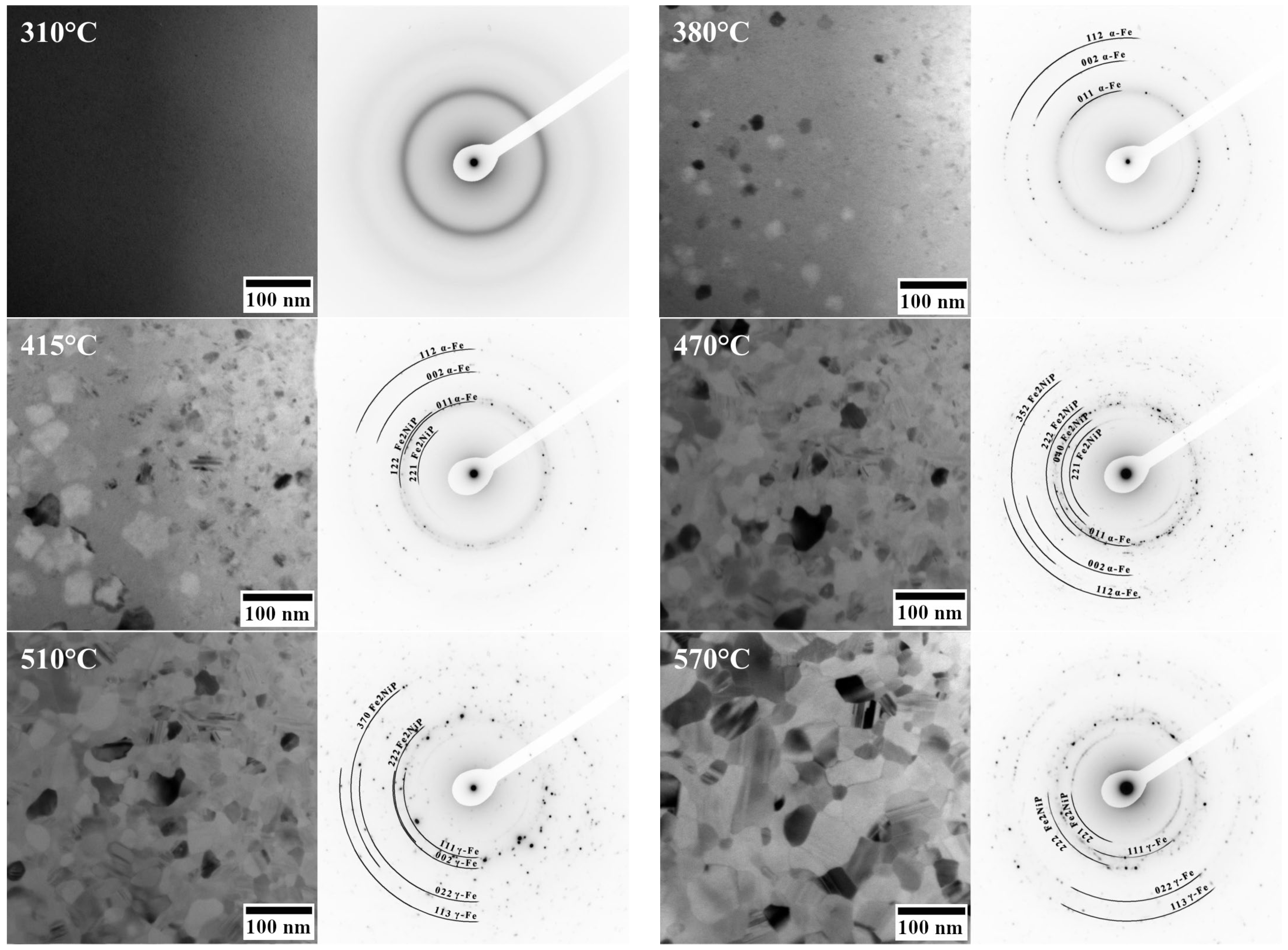
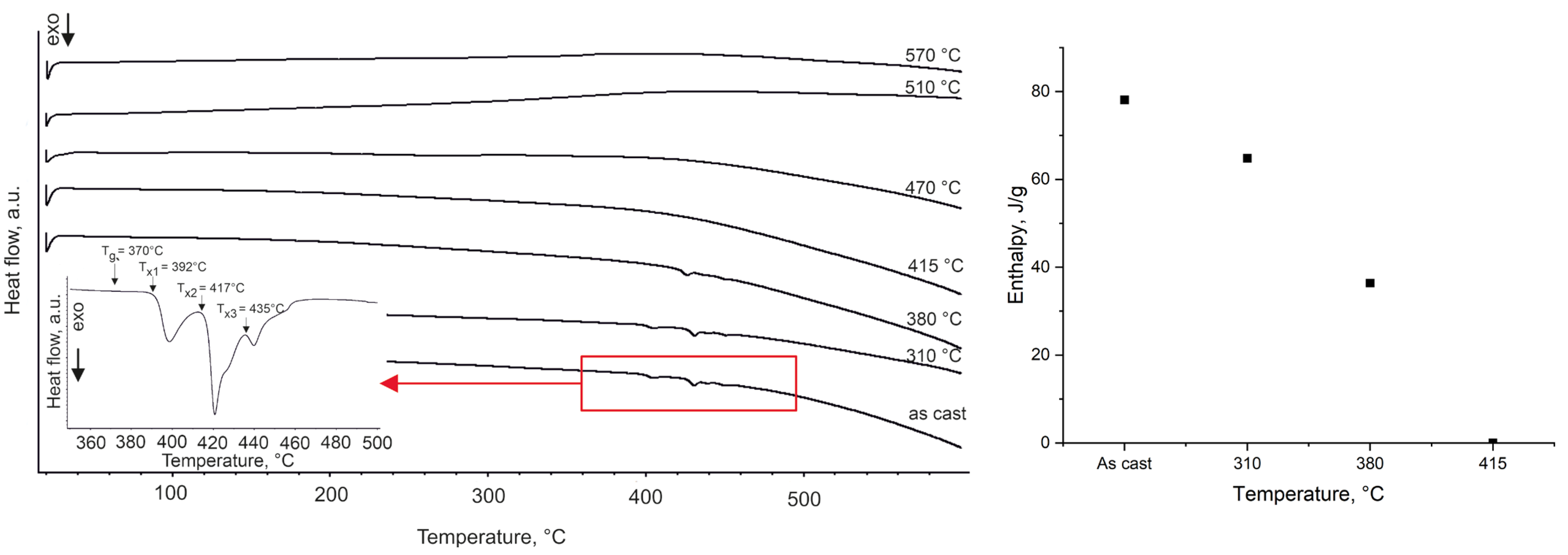
3.1. Phase Transformation

The X-ray diffractograms of the Fe62Ni18P13C7 annealed ribbons are presented in Figure 1.
The ribbons remain fully amorphous (no crystalline diffraction peaks) up to an annealing temperature of 310 °C. Upon annealing at 380 °C, new diffraction peaks appear, indicating the nucleation of (Fe,Ni) and the Fe2NiP phases within the amorphous matrix. Due to overlapping fundamental peaks, it was not possible from XRD alone to unambiguously distinguish whether this intermediate (Fe,Ni) phase has the L10 or fcc crystal structure. In samples annealed at 415 °C, the intermediate (Fe,Ni) phase is no longer detected. Instead, new diffraction peaks corresponding to the α-(Fe,Ni) phase appear, while those related to the Fe2NiP phase become more pronounced. At 470 °C, the γ-(Fe,Ni) phase is observed, coexisting with the α-(Fe,Ni) phase. Additionally, alongside the Fe2NiP phase, the crystallization of another phosphide phase—(Fe,Ni)2(P,C) is detected. At higher annealing temperatures (510 °C, 570 °C), the γ-(Fe,Ni) phase coexists with phosphides.
In addition to conventional XRD measurements, in situ transmission electron microscopy (TEM) studies were carried out to monitor phase evolution during the devitrification process. The Debye ring patterns recorded during the heating are shown in Figure 2.
At 310 °C, only diffuse halos characteristic of the amorphous phase are observed (no crystalline spots or rings). Upon heating to 380 °C, the first crystallites nucleate within the amorphous matrix. The initial crystalline phase identified in the TEM at ~380 °C is α-(Fe,Ni). At 415 °C, the Fe2NiP phase appears and coexists with both the α-(Fe,Ni) solid solution and residual amorphous regions (regions between crystallites that have not yet interconnected). Further growth of the Fe2NiP phase is observed at 470 °C. At 510 °C, the α-(Fe,Ni) phase undergoes transformation into the γ-(Fe,Ni) phase. Twin boundaries, characteristic of austenitic phases, are clearly visible at this stage. At 570 °C, a significant increase in grain size is observed, although no additional new phases are detected. It is noteworthy that there is a discrepancy between the in situ TEM observations and the ex situ XRD results at the 380 °C stage: while XRD indicated the presence of an ordered (Fe,Ni) phase of L10 or fcc structure, the in situ TEM (with a much shorter effective exposure at 380 °C) showed only α-(Fe,Ni) crystals.
The differential scanning calorimetry (DSC) curve of the investigated alloy is presented in Figure 3.
The glass transition region is narrow, and the width of the supercooled liquid region ΔTx (defined as Δ T x = T x T g , where Tg is the glass transition temperature and Tx is the onset temperature of crystallization) is approximately 22 °C. Three exothermic peaks are observed, with the primary crystallization onset at Tx1 ≈ 392 °C, a second crystallization event at Tx2 ≈ 417 °C, and a third, smaller exothermic event at Tx3 ≈ 435 °C. These multiple exotherms indicate a multistage devitrification process. Analysis of the crystallization enthalpies reveals a progressive decrease in the amorphous phase fraction as annealing temperature increases (Figure 3). The crystallization exothermic enthalpy of a ribbon annealed at 310 °C corresponds to an estimated ~83% remaining amorphous fraction, which drops to ~47% after annealing at 380 °C. Ribbons annealed at or above 415 °C show essentially no residual amorphous phase by this DSC criterion, consistent with those samples being fully crystalline.

3.2. Hardness Evolution
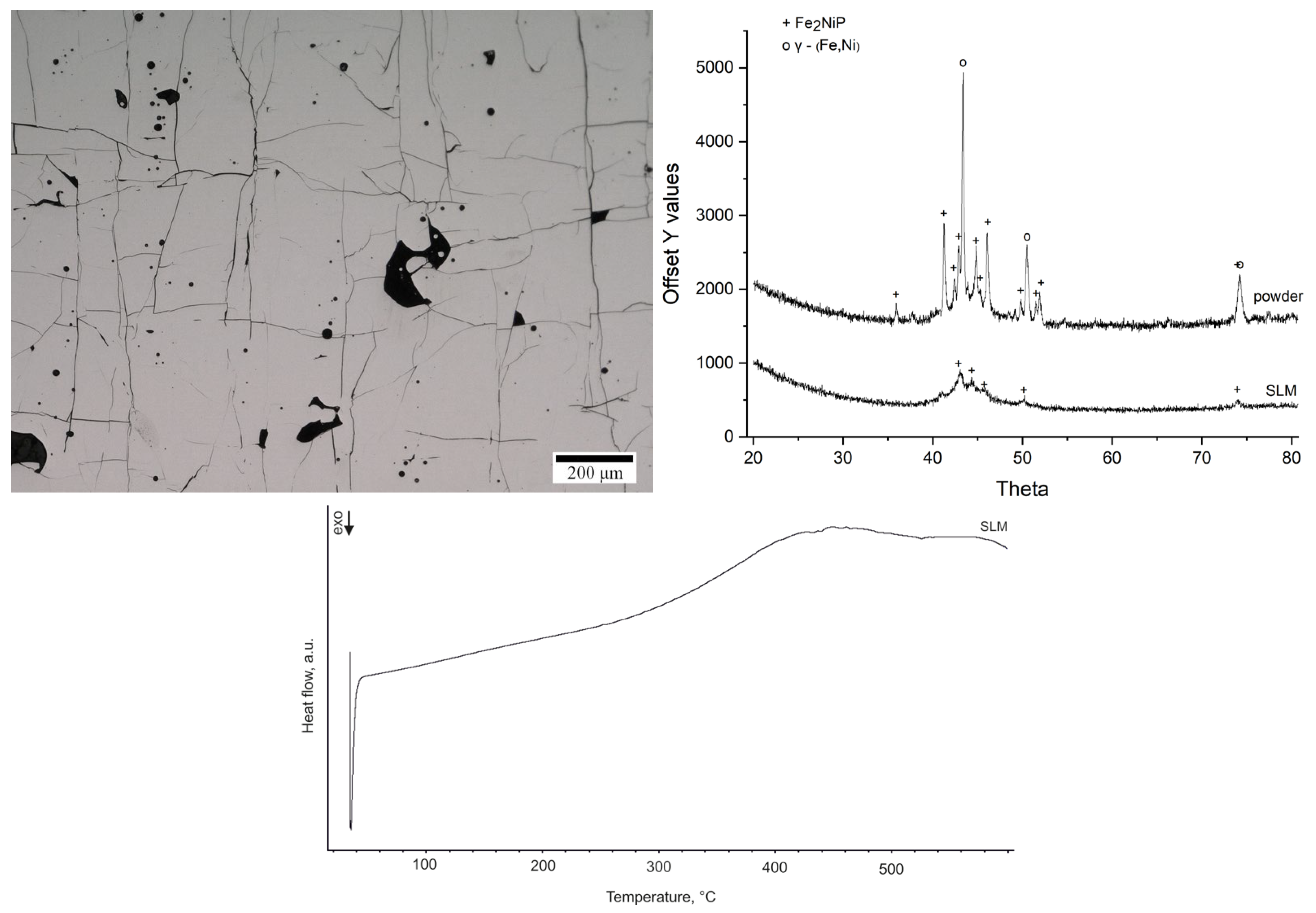
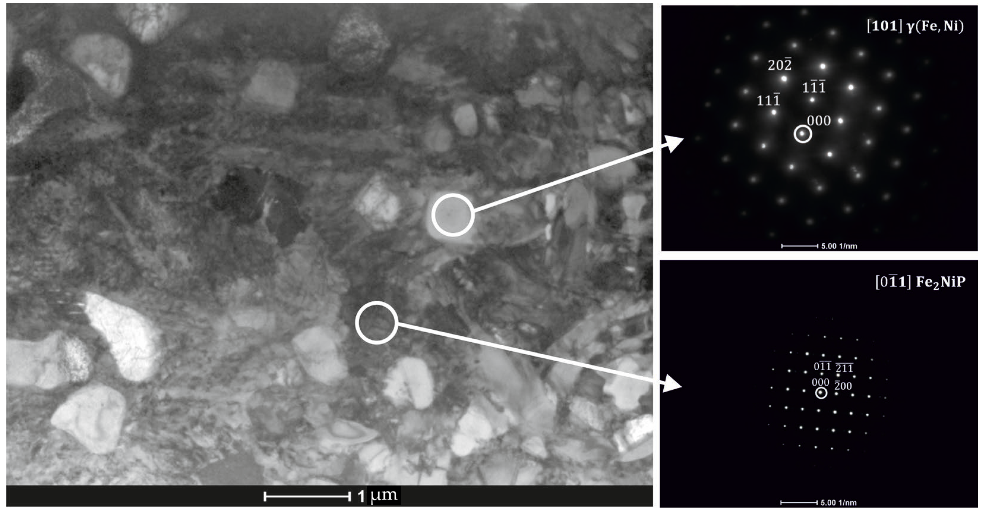
The evolution of hardness with annealing temperature is presented in Figure 4.
The hardness of the as-cast ribbon was approximately 8500 MPa. With increasing annealing temperature up to 415 °C, the hardness increases markedly, by about 50%, reaching roughly 12,500 MPa at 415 °C. In the intermediate temperature range between 415 °C and 510 °C, the hardness remains relatively constant, on the order of ~12,500–13,000 MPa. However, at the highest annealing temperature of 570 °C, a significant drop in hardness is observed, with the hardness decreasing by approximately 1500 MPa compared to the 510 °C condition. Thus, the hardness vs. temperature curve shows an initial rise, a plateau between ~415–510 °C, and then a decline at 570 °C.

3.3. SLM Printing

The microstructure of the printed sample produced from Fe62Ni18P13C7 powder is shown in Figure 5.
It reveals a consistent, irregular square grid of cracks throughout the structure, accompanied by the presence of pores. The phase constitution of the feedstock powder and the SLM-fabricated sample was examined by XRD (Figure 5). The XRD pattern of the as-received powder shows that the alloy powder was predominantly crystalline prior to printing, with strong diffraction peaks corresponding to the γ-(Fe,Ni) and Fe2NiP phases. This observation is consistent with the low glass-forming ability of Fe62Ni18P13C7 alloy. After SLM processing, the XRD pattern of the printed sample still shows the presence of the Fe2NiP phase, although its diffraction peaks are less intense compared to the powder. Peaks corresponding to the γ-(Fe,Ni) phase are absent, suggesting that during laser melting and rapid solidification, part of the γ-phase present in the powder either partially dissolved or transformed, and Fe2NiP crystallized from the melt in its place. The DSC curve of the printed sample (Figure 5) indicates that the SLM sample is nearly fully crystallized. Only a very small residual exothermic signal is observed upon heating, which corresponds to an estimated ~1.9% amorphous fraction remaining in the printed material (calculated by comparing the crystallization enthalpy of the printed sample to that of a fully amorphous ribbon).
The measured hardness for the printed sample was 10,200 ± 600 MPa. This hardness value is consistent with a mostly crystalline material that still contains a minor fraction of amorphous phase or is very fine. The presence of a crack grid prevents further mechanical testing of the sample.
Further microscopic analysis of the SLM sample was conducted using STEM-EDS mapping. Elemental mapping in Figure 6 reveals two distinct regions: (i) localized phosphorus-enriched regions with widths up to ~500 nm, although the majority were significantly narrower and (ii) iron-enriched regions with widths up to 600 nm. The phosphorus-enriched zones correspond to the Fe2NiP phase, and Fe-rich areas might be assigned to the γ-(Fe,Ni) type solid solution (Figure 7).
From the maps, it is evident that the volume fraction of the Fe2NiP phase is larger than that of the γ-(Fe,Ni) phase in these local areas, consistent with the pronounced P segregation. Overall, the microstructure of the SLM-fabricated alloy consists of a brittle Fe2NiP intermetallic network intermixed with regions of γ-(Fe,Ni) solid solution. Notably, α-(Fe,Ni) was not observed in the as-printed sample; the iron-rich phase present after SLM is in the γ-(Fe,Ni) form.

4. Discussion

4.1. Phase Transformation

Upon annealing the Fe62Ni18P13C7 ribbons, the alloy undergoes a multistage crystallization process. The XRD and TEM results together indicate that the first crystalline phase to form is around 380 °C. XRD suggests this phase could be the L10-FeNi (tetrataenite) or fcc-FeNi (taenite), phase but distinguishing between these ordered structures by conventional XRD is challenging due to overlapping fundamental peaks and the requirement to observe superlattice reflections, which are typically very weak and often fall below the detection limit of conventional XRD measurements [23]. Tetrataenite (L10-FeNi), if formed, is noteworthy because it is a highly ordered FeNi phase known for its exceptional magnetic properties [24]. It was first discovered in meteorites [25,26]. The L10-crystal structure belongs to the P4/mmm space group and typically forms near equiatomic compositions (50:50 atomic%) in certain alloy systems. In most cases, the L10-phase forms via a nucleation-and-growth mechanism from the disordered parent A1 (fcc) phase, below a critical chemical order-disorder temperature [27]. In Fe-Ni alloys, tetrataenite is typically obtained during slow cooling below ~320 °C, as atomic rearrangement from the disordered face-centered cubic taenite phase into a tetragonal distorted face-centered cubic cell requires long-range diffusion [28]. Under natural conditions, such as those found in meteorites, this process can take over 104 years due to the extremely low diffusion rates at these temperatures [28]. In laboratory studies, alternative synthesis routes for tetrataenite have been explored, such as the annealing of metallic glasses [29] or cyclic oxidation-reduction of nickel-coated iron particles [30]. In the case of Fe-Ni-P-C alloys, the crystallization of tetrataenite is believed to be closely related to the presence of phosphorus. Phosphorus significantly enhances the mobility of nickel atoms, particularly at low temperatures in the range of 300–700 °C [31]. The model proposed by Ke et al. [31] predicts a tenfold acceleration of vacancy-mediated solvent diffusion at temperatures below 600 °C when the phosphorus content exceeds 0.1 at.%. Therefore, conditions are favorable for the formation of ordered Fe–Ni phases during annealing of this alloy, despite the kinetic constraints that usually prevent their formation on laboratory timescales.
The appearance of the intermediate (Fe,Ni) phase around 380 °C in the ribbons is accompanied by the onset of nucleation of the Fe2NiP intermetallic compound, so the (Fe,Ni)3P type phase. Fe2NiP (schreibersite) is a brittle intermetallic compound, with a reported hardness in the range of 800–950 HV [32]. Its formation contributes significantly to the embrittlement of metallic glasses upon crystallization.
By 415 °C, the XRD data show that the initial (Fe,Ni) phase present at 380 °C has disappeared, replaced by a mixture of α-(Fe,Ni) and phosphide phases. This suggests that the intermediate phase was metastable and decomposed upon further heating. At this stage, the predominant phases are α-(Fe,Ni), a ferromagnetic bcc phase, and Fe2NiP. At higher temperatures, the α-(Fe,Ni) phase partially transforms into the γ-(Fe,Ni) phase. The observed sequence of phase evolutions is in agreement with reported phase transformations in Fe–Ni–P alloys [33]. The stabilization of γ-(Fe,Ni) (fcc) over α-(Fe,Ni) (bcc) at elevated temperature is consistent with the Fe–Ni binary phase behavior, where higher Ni content and higher temperatures favor the fcc phase [34]. The crystallization pattern is relevant to the structural relaxation and embrittlement behavior of metallic glasses upon annealing. In particular, (Fe100−xNix)83B17 metallic glasses have been shown to exhibit embrittlement only in compositions that crystallize predominantly into the bcc phase [35]. In this study, the Fe62Ni18P13C7 ribbons crystallized primarily into α-(Fe,Ni) at lower annealing temperatures, which would suggest a risk of embrittlement. At higher temperatures, α-(Fe,Ni) transformed to γ-(Fe,Ni). The eventual presence of γ-phase (especially in combination with a fine microstructure) could mitigate some embrittlement, but in practice, the extensive precipitation of Fe2NiP likely dominates and causes brittleness regardless of α or γ matrix phase.
It is worth noting a discrepancy between the in situ TEM observations and the XRD results for samples annealed at 380 °C. While XRD suggests the formation of an L10-FeNi or fcc-FeNi type phase, the in situ TEM analysis reveals only the presence of α-(Fe,Ni). This difference is likely attributable to the significantly shorter exposure times during the in situ TEM heating experiments and hence the lack of time for atoms to rearrange.
Thermal parameters from DSC reinforce the conclusion that Fe62Ni18P13C7 has a low glass-forming ability and multistage crystallization pattern. The glass-forming ability (GFA) of an alloy is often characterized parameters such as the critical cooling rate (Rc) and critical casting diameter (Dc), where Rc represents the minimum cooling rate required to suppress crystallization and achieve a fully amorphous structure, while Dc denotes the maximum sample dimension that allows for the formation of a completely amorphous phase [36]. Additionally, GFA can be estimated using various thermal parameters derived from DSC analysis [37]. One of the most commonly used indicators is the width of the supercooled liquid region (ΔTx) [37]. Alloys with a small, supercooled liquid region (ΔTx) require high cooling rates to form an amorphous structure and tend to crystallize easily upon any thermal input. The measured ΔTx of 22 °C matches well with literature data. For example, Ma et al. [16] reported the ΔTx of 23 °C for a 2.3 mm diameter rod cast from a similar alloy composition, Fe80Ni20P13C7. The fact that the atomized powder was largely crystalline (as shown by XRD) further illustrates the difficulty of retaining an amorphous structure in this composition without extremely high cooling rates or special processing. The DSC curve reveals multiple closely spaced exothermic events, which are indicative of a complex, multistage crystallization process. The first crystallization peak is most likely associated with the formation of the α-(Fe,Ni) phase, followed by a second event corresponding to the nucleation of the Fe2NiP intermetallic compound. The third exothermic peak is also observed at a higher temperature. Since no new phases are detected by TEM at 470 °C (Figure 2), this final thermal event is likely related to further ordering or the continued crystallization of the Fe2NiP phase that initially formed around Tx2.

4.2. Hardness Evolution

Annealing has a pronounced influence on the hardness evolution of the Fe62Ni18P13C7 alloy. A ~50% increase in hardness between the as-cast state and samples annealed at 415 °C may be attributed to structural transformations occurring within this temperature range. Specifically, up to 415 °C, nanocrystallization takes place, leading to the formation of α-(Fe,Ni) nanocrystals, as well as the initial precipitation of Fe2NiP intermetallic, as supported by both XRD and TEM data. The development of these nanometer-scale phases induces classic dispersion strengthening: the presence of hard particles (1000 HV 0.05 for Fe3P and 1100 HV 0.05 for Fe2P [38]) and refined α-(Fe,Ni) grains effectively impedes plastic deformation, thereby elevating the overall hardness. This phenomenon aligns with the strengthening behavior observed in other partially crystallized metallic glasses [39,40,41]. Crystallite size grows from ~20 nm to ~50 nm between 380 °C and 415 °C (Figure 2), enhancing hardness via dispersion strengthening up to an optimal size (~50 nm) [40,41]. Between 415 °C and 510 °C, the alloy retains its elevated hardness, despite continued microstructural evolution. Between 415 °C and 470 °C, the amorphous fraction diminishes further, and the volume fraction of both α-(Fe,Ni) and Fe2NiP increases. At 470 °C, the alloy becomes fully crystalline, primarily consisting of α-(Fe,Ni) and Fe2NiP. Then, the α-(Fe,Ni) transforms to γ-(Fe,Ni). The α-Fe phase typically exhibits higher hardness than γ-Fe, and its hardness remains more stable with temperature [42]. Two opposing effects appear to balance each other: (i) the transformation of the harder α-phase to the softer γ-(Fe,Ni) phase begins around 470–510 °C, while (ii) the volume fraction of hard Fe2NiP continues to grow. The retention of significant α-phase content and the presence of additional phosphide precipitates likely offset the inherent softness of the emerging γ-phase, maintaining overall high hardness. At 570 °C, however, a marked drop in hardness is observed due to further reduction of α-phase content and grain coarsening.

4.3. SLM Printing

The SLM processing results provide insight into the challenges of additively manufacturing alloys with low GFA, such as Fe62Ni18P13C7. The printed samples suffered from extensive cracking, which is consistent with reports in the literature that Fe-based metallic glass forming alloys tend to crack during laser powder bed fusion [6]. The use of a random hatch remelting strategy was motivated by its previously reported effectiveness in reducing crystallinity in another low-GFA alloy, Fe71Si10B11C6Cr2 (at.%), as demonstrated by Zrodowski et al. [7]. In the present work, the two-stage scanning approach (premelt followed by remelt) similarly failed to produce a fully amorphous structure in the Fe62Ni18P13C7 alloy. Nonetheless, it appears to have influenced the resulting phase distribution: the printed sample retained a minor amorphous fraction (~1.9%) and exhibited a reduced fraction of the γ-(Fe,Ni) phase compared to the initial powder. Essentially, the laser parameters were sufficient to melt the powder and homogenize it briefly in the melt pool, but as the melt pool cooled and subsequently experienced reheating from nearby scan tracks, the alloy could not avoid crystallization.
The formation of a crack network in the SLM sample can be attributed to several factors. First, the alloy’s poor glass-forming ability means it crystallizes during solidification into brittle phases. Second, the rapid cooling and repeated thermal cycling in SLM (as new layers are deposited) generate high internal stresses. The combination of a hard, brittle microstructure and high thermal stresses is conducive to crack initiation and propagation.
The pores observed in the microstructure can be classified into two types according to [43]: (A) small, round pores, typically referred to as hydrogen or metallurgical porosity, and (C) rectangular or triangular pores with sharp edges. The small gas porosity (A) might be minimized through drying of the powder and maintaining a high-purity inert atmosphere. The second type of pores (C) is inherently linked to the thermal stresses exceeding the material’s strength, leading to fracture and material detachment during metallographic preparation. This is consistent with the observed high density of cracks observed in the printed sample.
One intriguing aspect of the SLM sample is the presence of the γ-(Fe,Ni) phase, as opposed to the α-(Fe,Ni) that was the primary phase in annealed ribbons. The difference arises from the processing paths: the gas-atomized powder was largely γ to begin with (due to its solidification condition), and the SLM process, despite partial remelting, did not convert a γ-(Fe,Ni) to α-(Fe,Ni). Some γ-(Fe,Ni) phase was retained or re-formed upon solidification of the melt pools. It has been reported in the literature that if the triggering substrate exhibits any crystallographic matching with the phase to be nucleated, it can influence primary phase selection [34], which might also explain the formation of the γ-(Fe,Ni) phase. An additional factor is the nickel content, at lower Ni contents, the (Fe,Ni) solid solution adopts a body-centered cubic (bcc) structure, whereas at higher Ni contents, it transforms into a cubic close-packed (ccp, γ-phase) structure in (Fe-Ni)-based metallic glasses [34]. Since the formation of Fe2NiP consumes more Fe, it may promote the formation of the γ-(Fe,Ni) phase. The Fe-Ni-P-C systems are susceptible to liquid spinodal decomposition, even during conventional casting [44], which favors the formation of phosphides. Sarac et al. [14] showed that introducing nanometer-sized γ-(Fe,Ni) precipitates in an Fe–Ni–P–C bulk glass could dramatically increase compressive plasticity, by effectively lowering the shear modulus of the matrix and promoting the formation of numerous shear bands.
In our SLM sample, we have a γ-phase present along with the phosphides, but this did not translate into any observable improvement in cracking resistance. The crucial difference is the length scale and distribution of phases: in Sarac’s work [14], the γ precipitates were very fine and uniformly dispersed in an otherwise amorphous matrix, which optimally tuned the mechanical response. In the SLM-processed material, the microstructure is coarse and the brittle phase Fe2NiP forms a continuous network at the grain boundaries of the γ-(Fe,Ni). Such a microstructure is extremely prone to cracking because the brittle phase provides easy crack propagation paths, and the γ-phase islands are too large to arrest or deflect cracks effectively.
Overall, the SLM experiment on Fe62Ni18P13C7 highlights the challenge of processing low-GFA alloys additively. The random remelting strategy, while somewhat effective in reducing crystallinity (as also observed in [7]), was insufficient to achieve an amorphous structure or suppress cracking. The resulting microstructure, characterized by decreased γ-phase content, increased Fe2NiP, and a minor amorphous fraction, remained predominantly crystalline and brittle. A comparative approach, based on the analysis of annealed ribbons and SLM-processed samples, shows that while controlled annealing enables the formation of a fine nanostructured composite with high hardness, SLM solidification leads to a coarse, phase-separated structure with inferior mechanical resilience. Bridging this microstructural gap is essential for the successful additive manufacturing of such alloys.

5. Conclusions

Based on the conducted research, the following conclusions can be drawn:
The Fe62Ni18P13C alloy exhibits a narrow supercooled liquid region (ΔTx ≈ 22 °C) and readily crystallizes upon heating, indicating low glass-forming ability.
The annealing process induces multistage crystallization in the alloy. At approximately 380 °C, α-(Fe,Ni) (or a metastable (Fe,Ni) phase that subsequently decomposes into α-(Fe,Ni) and Fe2NiP) and Fe2NiP phases are formed. With increasing temperature, α-(Fe,Ni) transforms into γ-(Fe,Ni), accompanied by further phosphide growth.
Nanocrystallization increases hardness by ~50%, reaching ~12.5 GPa at 415 °C, due to the formation of fine α-(Fe,Ni) grains and Fe2NiP precipitates. Grain coarsening above 510 °C reduces hardness.
SLM processing results in a predominantly crystalline, brittle microstructure with only ~2% amorphous content and visible thermal cracking. Hardness of the as-printed sample (~10.2 GPa) reflects its phase composition.

Author Contributions

Conceptualization, A.M.; methodology, A.M., Ł.S., A.Ż. and Ł.Ż.; software, Ł.S. and Ł.M.; validation, A.M.; formal analysis, A.M. and Ł.S.; investigation, A.M., Ł.S., A.Ż., Ł.Ż., Ł.M. and W.P.; resources, A.M., A.Ż., Ł.Ż., Ł.M. and W.P.; data curation, A.M., Ł.S., A.K., Ł.M. and W.P.; writing—original draft preparation, A.M.; writing—review and editing, A.M., A.Ż. and W.P.; visualization, A.M. and Ł.S.; supervision, A.M.; project administration, A.M.; funding acquisition, A.M. All authors have read and agreed to the published version of the manuscript.

Funding

The presented research results were obtained as part of the research task entitled “Crystallization in iron-based metallic glasses” funded by the pro-quality subsidy for the development of the research potential of the Faculty of Mechanical Engineering, Wrocław University of Science and Technology, in the year 2022.

Institutional Review Board Statement

Not applicable.

Informed Consent Statement

Not applicable.

Data Availability Statement

The original contributions presented in the study are included in the article, further inquiries can be directed to the corresponding author.

Conflicts of Interest

Author Łukasz Żrodowski was employed by the company AMAZEMET Sp. z o. o. [Ltd.]. The remaining authors declare that the research was conducted in the absence of any commercial or financial relationships that could be construed as a potential conflict of interest.

References

  1. Pei, Z.; Ju, D. Simulation of the Continuous Casting and Cooling Behavior of Metallic Glasses. Materials 2017, 10, 420. [Google Scholar] [CrossRef] [PubMed]
  2. Pauly, S.; Löber, L.; Petters, R.; Stoica, M.; Scudino, S.; Kühn, U.; Eckert, J. Processing metallic glasses by selective laser melting. Mater. Today 2013, 16, 37–41. [Google Scholar] [CrossRef]
  3. Nong, X.D.; Zhou, X.L.; Ren, Y.X. Fabrication and characterization of Fe-based metallic glasses by Selective Laser Melting. Opt. Laser Technol. 2019, 109, 20–26. [Google Scholar] [CrossRef]
  4. Erutin, D.; Popovich, A.; Sufiiarov, V. Comparative Study of Microstructure and Phase Composition of Amorphous-Nanocrystalline Fe-Based Composite Material Produced by Laser Powder Bed Fusion in Argon and Helium Atmosphere. Materials 2024, 17, 2343. [Google Scholar] [CrossRef]
  5. Löfstrand, J.; Goetz, I.K.; Marattukalam, J.J.; Hjörvarsson, B.; Nagy, G.; Skårman, B.; Sahlberg, M.; Jönsson, P.E. Stress related magnetic imaging of iron-based metallic glass produced with laser beam powder bed fusion. Mater. Des. 2024, 244, 113199. [Google Scholar] [CrossRef]
  6. Zhang, P.; Tan, J.; Tian, Y.; Yan, H.; Yu, Z. Research progress on selective laser melting (SLM) of bulk metallic glasses (BMGs): A review. Int. J. Adv. Manuf. Technol. 2022, 118, 2017–2057. [Google Scholar] [CrossRef]
  7. Żrodowski, Ł.; Wysocki, B.; Wróblewski, R.; Krawczyńska, A.; Adamczyk-Cieślak, B.; Zdunek, J.; Błyskun, P.; Ferenc, J.; Leonowicz, M.; Święszkowski, W. New approach to amorphization of alloys with low glass forming ability via selective laser melting. J. Alloys Compd. 2019, 771, 769–776. [Google Scholar] [CrossRef]
  8. Zhang, P.; Zhang, C.; Ouyang, D.; Liu, L. Enhancement of plasticity and toughness of 3D printed binary Zr50Cu50 bulk metallic glass composite by deformation-induced martensitic transformation. Scr. Mater. 2021, 192, 7–12. [Google Scholar] [CrossRef]
  9. Zou, Y.; Qiu, Z.; Tan, C.; Wu, Y.; Li, K.; Zeng, D. Microstructure and mechanical properties of Fe-based bulk metallic glass composites fabricated by selective laser melting. J. Non-Cryst. Solids 2020, 538, 120046. [Google Scholar] [CrossRef]
  10. Guo, S.F.; Liu, L.; Li, N.; Li, Y. Fe-based bulk metallic glass matrix composite with large plasticity. Scr. Mater. 2010, 62, 329–332. [Google Scholar] [CrossRef]
  11. Wu, Y.; Wang, H.; Wu, H.H.; Zhang, Z.Y.; Hui, X.D.; Chen, G.L.; Ma, D.; Wang, X.L.; Lu, Z.P. Formation of Cu–Zr–Al bulk metallic glass composites with improved tensile properties. Acta Mater. 2011, 59, 2928–2936. [Google Scholar] [CrossRef]
  12. Yüce, E.; Sarac, B.; Ketov, S.; Reissner, M.; Eckert, J. Effects of Ni and Co alloying on thermal, magnetic and structural properties of Fe-(Ni,Co)-P-C metallic glass ribbons. J. Alloys Compd. 2021, 872, 159620. [Google Scholar] [CrossRef]
  13. Guo, S.F.; Qiu, J.L.; Yu, P.; Xie, S.H.; Chen, W. Fe-based bulk metallic glasses: Brittle or ductile? Appl. Phys. Lett. 2014, 105, 161901. [Google Scholar] [CrossRef]
  14. Sarac, B.; Ivanov, Y.P.; Chuvilin, A.; Schöberl, T.; Stoica, M.; Zhang, Z.; Eckert, J. Origin of large plasticity and multiscale effects in iron-based metallic glasses. Nat. Commun. 2018, 9, 1333. [Google Scholar] [CrossRef] [PubMed]
  15. Walter, J.L.; Luborsky, F.E. The ductile-brittle transition of some amorphous alloys. Mater. Sci. Eng. 1978, 33, 91–94. [Google Scholar] [CrossRef]
  16. Ma, X.; Yang, X.; Li, Q.; Guo, S. Quaternary magnetic FeNiPC bulk metallic glasses with large plasticity. J. Alloys Compd. 2013, 577, 345–350. [Google Scholar] [CrossRef]
  17. Pang, B.; Long, Z.; Long, T.; He, R.; Liu, X.; Pan, M. Accelerated discovery of Fe-based amorphous/nanocrystalline alloy through explicit expression and interpretable information based on machine learning. Mater. Des. 2023, 231, 112054. [Google Scholar] [CrossRef]
  18. Budhani, R.C.; Goel, T.C.; Chopra, K.L. Melt-spinning technique for preparation of metallic glasses. Bull. Mater. Sci. 1982, 4, 549–561. [Google Scholar] [CrossRef]
  19. Stoica, M.; Kumar, S.; Roth, S.; Ram, S.; Eckert, J.; Vaughan, G.; Yavari, A.R. Crystallization kinetics and magnetic properties of Fe66Nb4B30 bulk metallic glass. J. Alloys Compd. 2009, 483, 632–637. [Google Scholar] [CrossRef]
  20. Małachowska, A.; Żrodowski, Ł.; Morończyk, B.; Maj, Ł.; Kuś, A.; Lampke, T. Selective Laser Melting of Fe-Based Metallic Glasses with Different Degree of Plasticity. Metall. Mater. Trans. A 2023, 54, 658–670. [Google Scholar] [CrossRef]
  21. Janovszky, D.; Sveda, M.; Sycheva, A.; Kristaly, F.; Zámborszky, F.; Koziel, T.; Bala, P.; Czel, G.; Kaptay, G. Amorphous alloys and differential scanning calorimetry (DSC). J. Therm. Anal. Calorim. 2022, 147, 7141–7157. [Google Scholar] [CrossRef]
  22. Kim, J.; Kim, S.; Suh, J.-Y.; Kim, Y.J.; Kim, Y.K.; Choi-Yim, H. Properties of a rare earth free L10-FeNi hard magnet developed through annealing of FeNiPC amorphous ribbons. Curr. Appl. Phys. 2019, 19, 599–605. [Google Scholar] [CrossRef]
  23. Klinger, M.; Jäger, A. Crystallographic Tool Box (CrysTBox): Automated tools for transmission electron microscopists and crystallographers. J. Appl. Crystallogr. 2015, 48, 2012–2018. [Google Scholar] [CrossRef]
  24. Mandal, S.; Debata, M.; Sengupta, P.; Basu, S. L10FeNi: A promising material for next generation permanent magnets. Crit. Rev. Solid State Mater. Sci. 2022, 48, 703–725. [Google Scholar] [CrossRef]
  25. Albertsen, J.F.; Knudsen, J.M.; Jensen, G.B. Structure of taenite in two iron meteorites. Nature 1978, 273, 453–454. [Google Scholar] [CrossRef]
  26. Petersen, J.F.; Aydin, M.; Knudsen, J.M. Mössbauer spectroscopy of an ordered phase (superstructure) of FeNi in an iron meteorite. Phys. Lett. A 1977, 62, 192–194. [Google Scholar] [CrossRef]
  27. Zhang, B.; Lelovic, M.; Soffa, W.A. The formation of polytwinned structures in Fe Pt and Fe Pd alloys. Scr. Metall. Mater. 1991, 25, 1577–1582. [Google Scholar] [CrossRef]
  28. Dos Santos, E.; Gattacceca, J.; Rochette, P.; Fillion, G.; Scorzelli, R.B. Kinetics of tetrataenite disordering J. Magn. Magn. Mater. 2015, 375, 234–241. [Google Scholar] [CrossRef]
  29. Sharma, P.; Zhang, Y.; Makino, A. Magnetic Properties of L1 0 FeNi Phase Developed Through Annealing of an Amorphous Alloy. IEEE Trans. Magn. 2017, 53, 2100910. [Google Scholar] [CrossRef]
  30. Lima, E.; Drago, V. A New Process to Produce Ordered Fe50Ni50 Tetrataenite. Phys. Status Solidi A 2001, 187, 119–124. [Google Scholar] [CrossRef]
  31. Ke, J.-H.; Young, G.A.; Tucker, J.D. Ab initio study of phosphorus effect on vacancy-mediated process in nickel alloys—An insight into Ni2Cr ordering. Acta Mater. 2019, 172, 30–43. [Google Scholar] [CrossRef]
  32. Ghosh, S.; Ray, D.; Murty, S. Raghunathpura: An early crystallised IIAB iron with sulphide micro nodules. Adv. Space Res. 2016, 58, 1879–1892. [Google Scholar] [CrossRef]
  33. Houghton, O.S.; Loudon, J.C.; Twitchett-Harrison, A.C.; Panagiotopoulos, N.T.; Lampronti, G.I.; Costa, M.B.; Harrison, R.J.; Greer, A.L. Reinterpretation of Report of Tetrataenite in Bulk Alloy Castings. Adv. Sci. 2025, 12, 2408796. [Google Scholar] [CrossRef] [PubMed]
  34. Greer, A.; Walker, I. Primary crystallization in (Fe, Ni)-based metallic glasses. J. Non-Cryst. Solids 2003, 317, 78–84. [Google Scholar] [CrossRef]
  35. Lewis, B.G.; Davies, H.A.; Ward, K.D. The crystallisation and associated changes in ductility of some Fe-Ni-B glassy alloys. Scr. Metall. 1979, 13, 313–317. [Google Scholar] [CrossRef]
  36. Li, X.; Kou, S.; Li, C.; Zhao, Y.; Ding, Y. A criterion of glass-forming ability and stability derived from pseudo-four characteristic temperatures. Intermetallics 2021, 134, 107201. [Google Scholar] [CrossRef]
  37. Suryanarayana, C.; Inoue, A. Iron-based bulk metallic glasses. Int. Mater. Rev. 2013, 58, 131–166. [Google Scholar] [CrossRef]
  38. Nowacki, J. Phosphorus in iron alloys surface engineering. J. Achiev. Mater. Manuf. Eng. 2007, 24, 57–67. [Google Scholar]
  39. Minnert, C.; Kuhnt, M.; Bruns, S.; Marshal, A.; Pradeep, K.G.; Marsilius, M.; Bruder, E.; Durst, K. Study on the embrittlement of flash annealed Fe85.2B9.5P4Cu0.8Si0.5 metallic glass ribbons. Mater. Des. 2018, 156, 252–261. [Google Scholar] [CrossRef]
  40. Han, J.; Wang, C.; Kou, S.; Liu, X. Thermal stability, crystallization behavior, Vickers hardness and magnetic properties of Fe–Co–Ni–Cr–Mo–C–B–Y bulk metallic glasses. Trans. Nonferrous Met. Soc. China 2013, 23, 148–155. [Google Scholar] [CrossRef]
  41. Pang, L.L.; Inoue, A.; Zanaeva, E.N.; Wang, F.; Bazlov, A.I.; Han, Y.; Kong, F.L.; Zhu, S.L.; Shull, R.B. Nanocrystallization, good soft magnetic properties and ultrahigh mechanical strength for Fe82-85B13-16Si1Cu1 amorphous alloys. J. Alloys Compd. 2019, 785, 25–37. [Google Scholar] [CrossRef]
  42. Torres, H.; Varga, M.; Ripoll, M.R. High temperature hardness of steels and iron-based alloys. Mater. Sci. Eng. A 2016, 671, 170–181. [Google Scholar] [CrossRef]
  43. Kuś, A.; Rajťúková, V.; Pilarczyk, W.; Hudák, R.; Mehner, T.; Maj, Ł.; Lampke, T.; Małachowska, A. First attempt to print Co-based alloys with high glass forming ability by selective laser melting. J. Alloys Compd. 2024, 995, 174680. [Google Scholar] [CrossRef]
  44. Yao, K.F.; Zhang, C.Q. Fe-based bulk metallic glass with high plasticity. Appl. Phys. Lett. 2007, 90, 61901. [Google Scholar] [CrossRef]
Figure 1. X-ray diffraction patterns of Fe62Ni18P13C7 ribbons annealed at given temperatures for 10 min in argon atmosphere, Cu-Kα radiation (λ = 1.5406 Å).
Materials 18 03376 g001
Figure 2. Selected area TEM images and corresponding Debye ring patterns recorded during in situ heating at a rate of 10 °C/min of Fe62Ni18P13C7 ribbons, illustrating the phase evolution from the amorphous state to crystalline phases at given temperatures.
Materials 18 03376 g002
Figure 3. DSC curve of the Fe62Ni18P13C7 alloy, indicating the glass transition (Tg), the onset of primary crystallization (Tx1), the second (Tx2) and third (Tx3) crystallization events, along with the curves for ribbons annealed at the specified temperatures. Measurements were carried out at a heating rate of 10 °C/min in a nitrogen atmosphere (left). Evolution of crystallization enthalpy with annealing temperature (right).
Materials 18 03376 g003
Figure 4. Indentation hardness (HIT) obtained from nanoindentation measurements of ribbons in the as-cast state and after annealing (10 min) (left) and an example of the obtained indents (right).
Materials 18 03376 g004
Figure 5. Microstructure of SLM printed sample (Keyence VHX-6000 digital microscope) (left); diffractogram of powder and printed sample, Cu-Kα radiation (λ = 1.5406 Å) (right); DSC curve of the printed sample at a heating rate of 10 °C/min in a nitrogen atmosphere (bottom).
Materials 18 03376 g005
Figure 6. STEM microstructure and elemental composition maps in the Fe62Ni18P13C7 SLM printed sample.
Materials 18 03376 g006
Figure 7. Transmission electron microscopy (TEM) image of Fe62Ni18P13C7 SLM-printed sample along with corresponding diffraction patterns identifying the γ-(Fe,Ni) solid solution and Fe2NiP phosphides.
Materials 18 03376 g007
Disclaimer/Publisher’s Note: The statements, opinions and data contained in all publications are solely those of the individual author(s) and contributor(s) and not of MDPI and/or the editor(s). MDPI and/or the editor(s) disclaim responsibility for any injury to people or property resulting from any ideas, methods, instructions or products referred to in the content.

