1. Introduction
Glass Fiber-Reinforced Polymers (GFRP) are increasingly common in structural engineering applications (bridge reinforcements, seismic retrofitting, and concrete strengthening) due to their superior material properties [
1]. For example, pultruded GFRP sections have been used as I- and C-sections in structural applications [
2]. Additionally, GFRP bars have been used as the main reinforcement in concrete structures exposed to seawater [
3]. The feasibility of using GFRP bars in structural applications has been shown in [
4,
5,
6]. The properties that make GFRP bars suitable for such applications include high tensile strength, high strength-to-weight ratio, corrosion resistance, and cost effectiveness over the long term [
7]. However, GFRP bars also suffer from several limitations that might hinder their widespread use. These limitations include low ductility, low modulus of elasticity, and low flexural strength [
8]. Another issue that can negatively affect the performance of GFRP bars in reinforced concrete structures is the bond slip between the concrete and the GFRP bars [
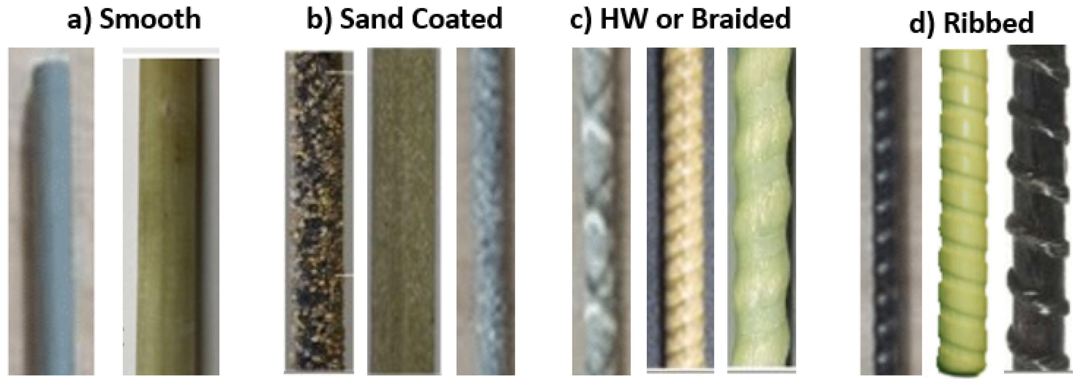
9]. Bond slip refers to the relative displacement that occurs between the reinforcing bar and the surrounding concrete and characterizes the load transfer between the concrete and the rebar through adhesion, friction, and mechanical interlocking. Due to their different material properties and surface textures, the bond behaviour of GFRP bars is different than that of steel bars. While steel bars are manufactured with ribs that enhance mechanical interlock by creating substantial bearing and shearing resistance along the length, GFRP bars usually have smoother surfaces and thus are unlikely to achieve the same level of mechanical interlock. Additionally, the ductility of steel bars allows the ribs to deform under load, which enhances mechanical interlock. On the other hand, the brittleness of GFRP bars limits their ability to form additional interlocks. This reduction in mechanical interlock in GFRP bars can be compensated for by increased friction that results from the use of coatings and other surface treatments. Additionally, while adhesion plays a minor role in the bond behavior of steel rebars, that role is further reduced in GFRP bars since the polymer matrix is largely inert to cement paste, which results in minimal chemical adhesion. Thus, the bond mechanism in steel rebars is mainly dominated by mechanical interlock, while the bond mechanism of GFRP bars is a combination of mechanical interlock and friction.
However, while the bond between concrete and steel has been thoroughly investigated throughout the years, GFRP bars have only recently been adopted in concrete structures, and therefore, their bond–slip behavior has not been fully characterized. Therefore, it is essential to perform a comprehensive review of the bond behavior of GFRP bars embedded in concrete and the factors that influence this bond to ensure a safe and reliable design. Such a review is also relevant to other types of FRP bars, as bond behavior depends on the surface of the FRP bars, and the findings of this review could apply to other types of FRP bars, such as CFRP and BFRP.
The manufacturing process has a significant effect on the bond behavior and other mechanical properties of GFRP bars [
10,
11,
12,
13,
14,
15,
16,
17,
18,
19,
20,
21,
22]. In addition, bond strength can be significantly influenced by other factors, such as concrete compressive strength, bar surface, bar size, bar location, and embedment length. Several experimental studies have been conducted to better understand the bond behavior of GFRP bars. For example, Ehsani et al. [
23] experimentally investigated the impact of GFRP surface preparation (
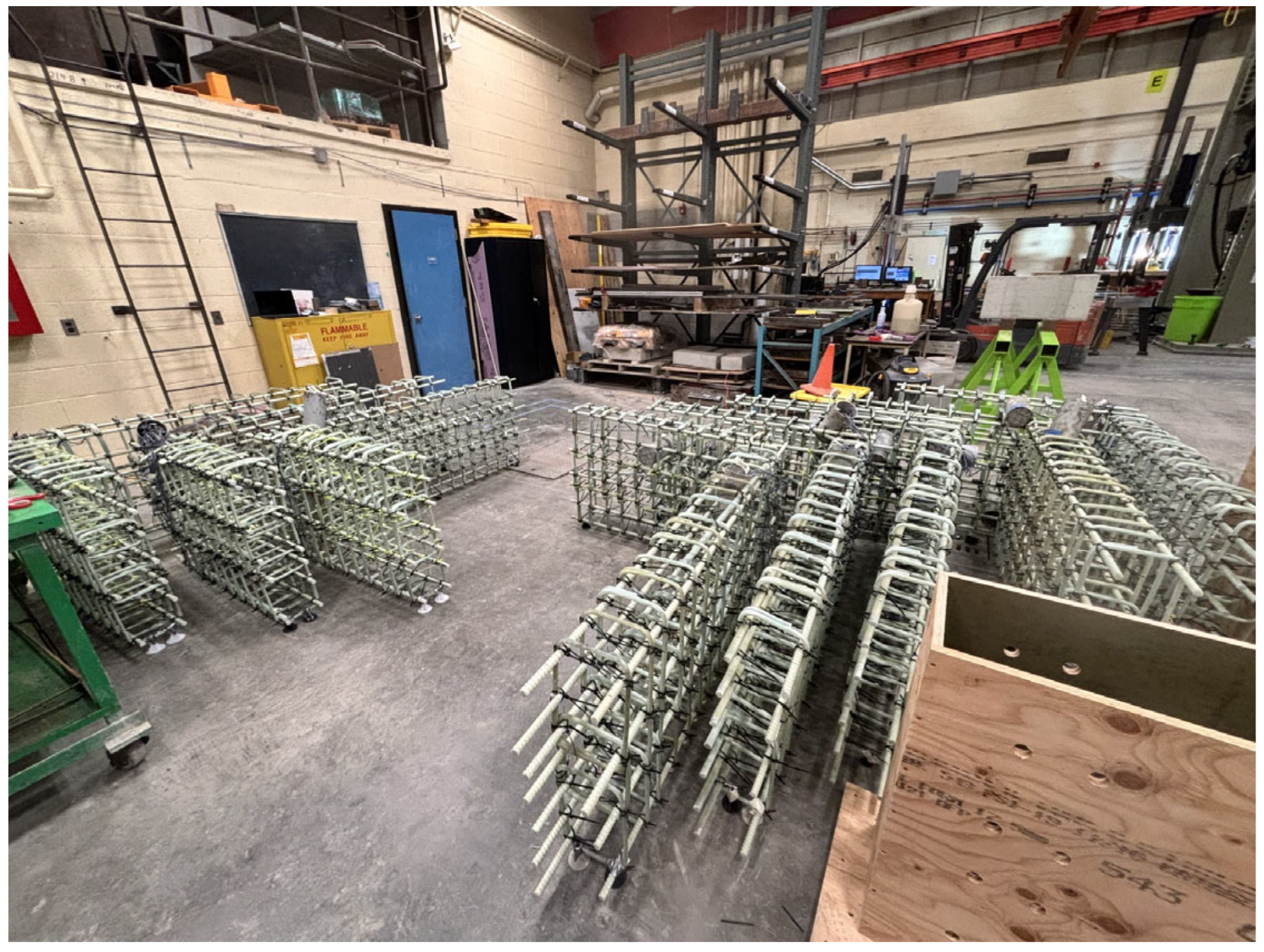
Figure 1 shows different surface types while
Figure 2 shows GFRP bars in application), loading conditions, concrete compressive strength, bar diameter, clear cover distance, and top bar effects on bond strength [
23]. Furthermore, several attempts have been made to model bond behavior in GFRP-reinforced concrete empirically and theoretically. The models use experimental data to establish and calibrate relationships between bond strength and various influencing factors.
While individual studies that investigate the bond behavior of GFRP bars, either experimentally or numerically, are available, a comprehensive review is needed to integrate fragmented research and enable the consolidation of dispersed knowledge, which will allow researchers and practitioners to access findings from a wide range of studies. The review would also help identify the key factors influencing the bond behavior of GFRP bars and help evaluate bond modelling accuracy to reveal suitability for practical applications. Furthermore, a systematic review provides a robust evidence base to help in the development and refinement of design codes and guidelines.
The objective of this paper is to provide an overview of the current state of research on bond behavior in GFRP-reinforced concrete. The study summarizes experimental investigations that directly measure bond strength and investigates the different factors that influence it. An overview of the analytical and empirical models used to simulate bond behavior and calibrate them against experimental results is then presented. Additionally, an overview of the expressions used in research and design guidelines to estimate the peak bond strength is also provided. A summary of current knowledge is provided, research gaps are identified, and practical application implications are highlighted. The database was compiled from various scientific publications indexed in leading databases, such as Scopus and Elsevier. The selection criteria for including journals in this review not only emphasized the impact factor and disciplinary relevance but also the rigor of peer review processes to ensure the inclusion of high-quality research.
2. Experimental Studies
The bond strength of reinforcing bars is typically measured using either pullout tests or beam tests [
25,
26]. The pullout test involves measuring the force required to directly pull out a bar embedded in the center of a concrete cylinder or prism. This kind of test provides direct measurements of the force magnitude and the corresponding slip, which can then be translated into a bond stress–slip relationship [
27]. The bond stress can be calculated from the force as per Equation (1), where
is the bond stress representing the strength of the bond between the steel and concrete,
is the pullout force,
is the bar diameter, and
is the embedment length. On the other hand, beam tests involve loading a specially designed reinforced concrete beam to bending failure, allowing researchers to observe and quantify how the bars slip relative to the concrete under realistic stress conditions [
28,
29]. While beam tests provide a more realistic estimate of bond strength, the value obtained from this test is usually a lower bound, while the pullout test provides an upper bound estimate. The reason for this discrepancy is that the main failure mechanism in pullout tests is pullout failure. Splitting of concrete is avoided in pullout tests due to the absence of local bending on the bar, higher thickness of the concrete cover, and the confining action of the reaction plate on the concrete specimen [
30]. On the other hand, failure in beam tests may be caused by either pulling out or splitting. However, despite the larger accuracy associated with beam tests, researchers tend to prefer pullout tests due to their simplicity [
30,
31]. It is noted that there are different types of beam and pullout tests (such as the standard pullout test, the eccentric pullout tests, the direct tension pullout test, the RILEM RC5 Beam test, and the lap splice beam test), with the standard pullout being the preferred test for bond slip in GFRP bars [
32]. Furthermore, both pullout and beam end tests are covered in testing standards. Pullout tests are covered in ASTM C900 [
33] and EN 12504-3 [
34], while beam tests are covered in standards, such as ASTM A944 [
35] and IS 2770-1 [
36].
Figure 3 depicts a standard pullout test, a beam end test, and a lap splice beam test. As mentioned, bond failure is characterized by either pullout or splitting failure. Pullout failure typically occurs in specimens with short embedment lengths and sufficient confinement, where bond stress is transferred without causing significant damage to the surrounding concrete and is characterized by bar slippage out of the concrete without significant cracking or damage to the surrounding concrete mass. In contrast, splitting failure arises when radial stress exceeds the tensile strength of the concrete, often in cases of longer embedment lengths, larger bar diameters, insufficient cover, or poor confinement and is characterized.
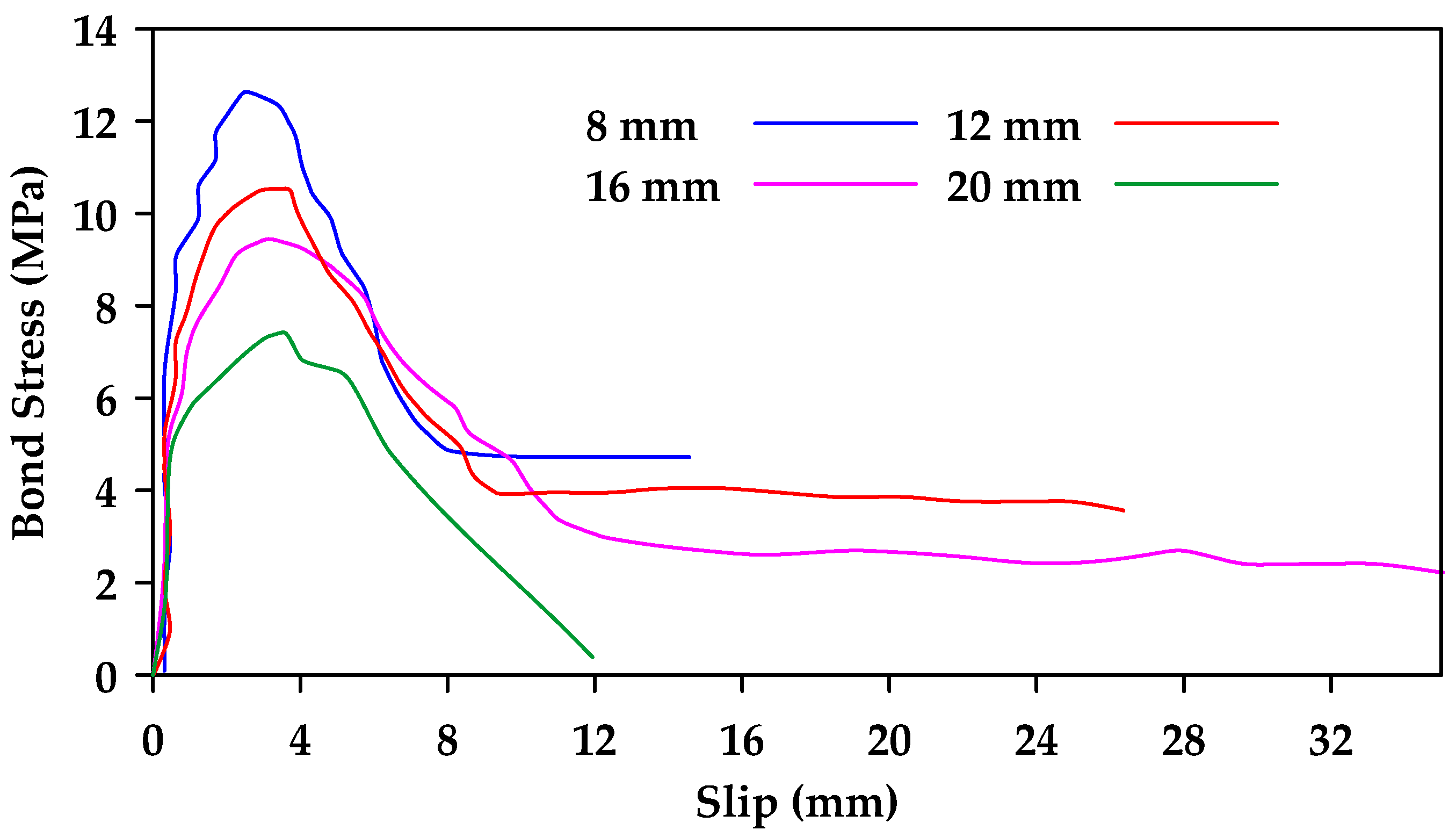
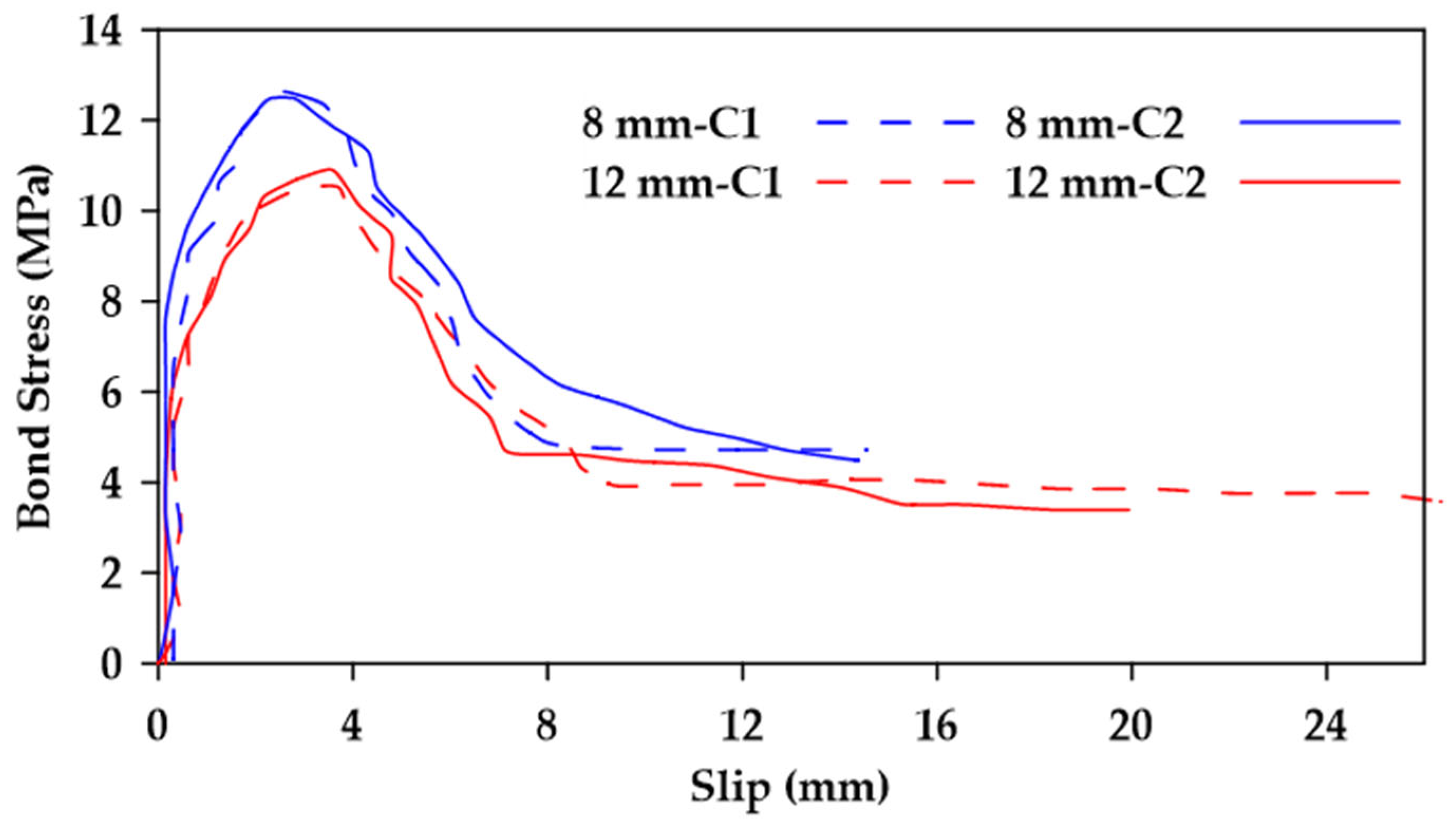
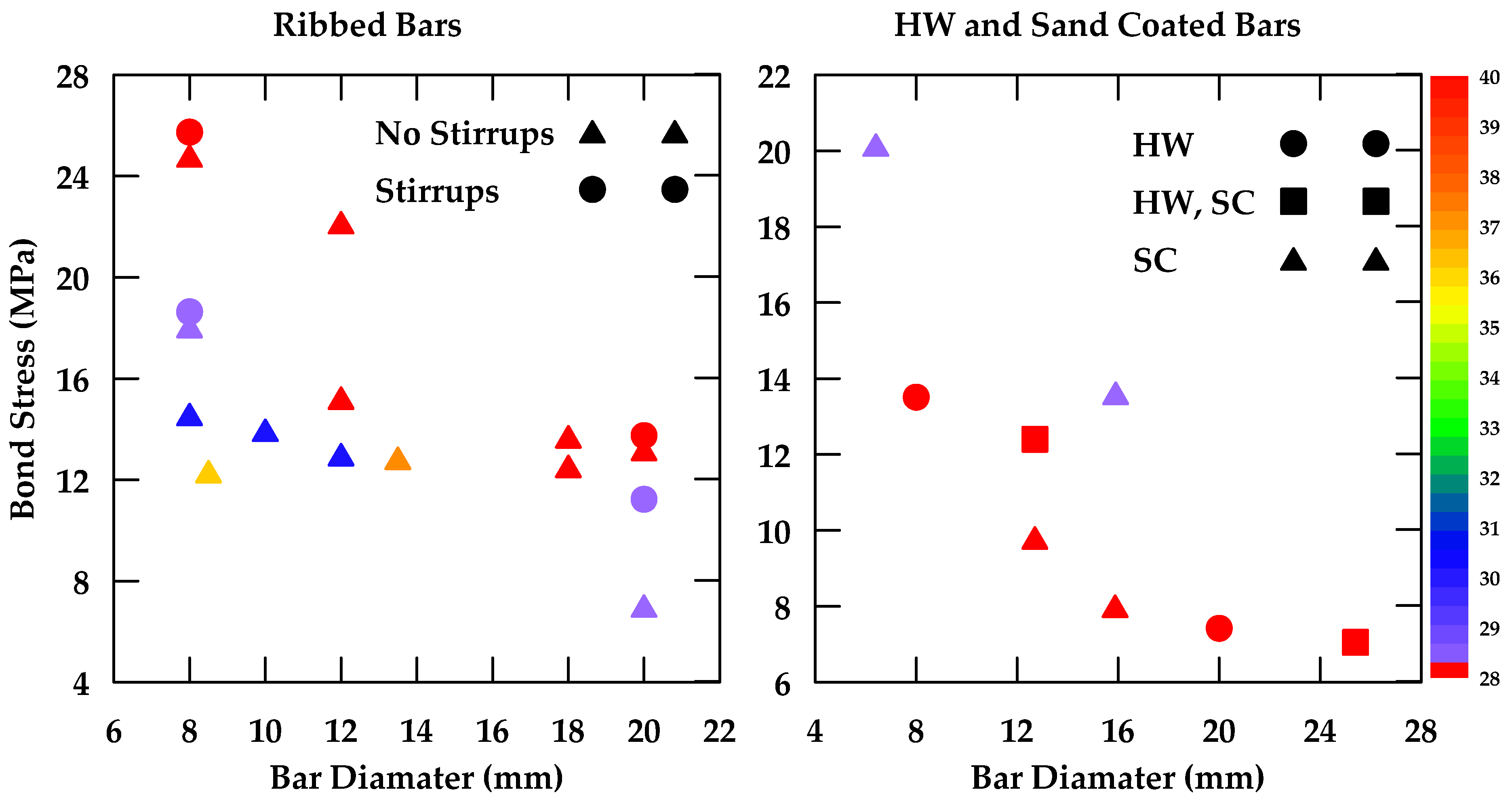
Gao et al. [
37] performed pullout tests on GFRP bars embedded in concrete and reported on the various variables that impinge upon bond behavior [
37]. The variables considered included the surface characteristics of the bars, the bar diameter, the concrete strength, as well as the confinement effect of stirrups. Four nominal diameters 8, 12, 16, and
) and three types of external surfaces were studied (helical wrapping, helical wrapping with sand coating, and ribbed). Additionally, two different concrete strengths were investigated (
and
). Furthermore, specimens with and without
stirrups spaced at
were tested. The embedment length used was
, where
d represents the bar diameter. The findings indicate that the bond strength decreases as the bar diameter increases as highlighted in
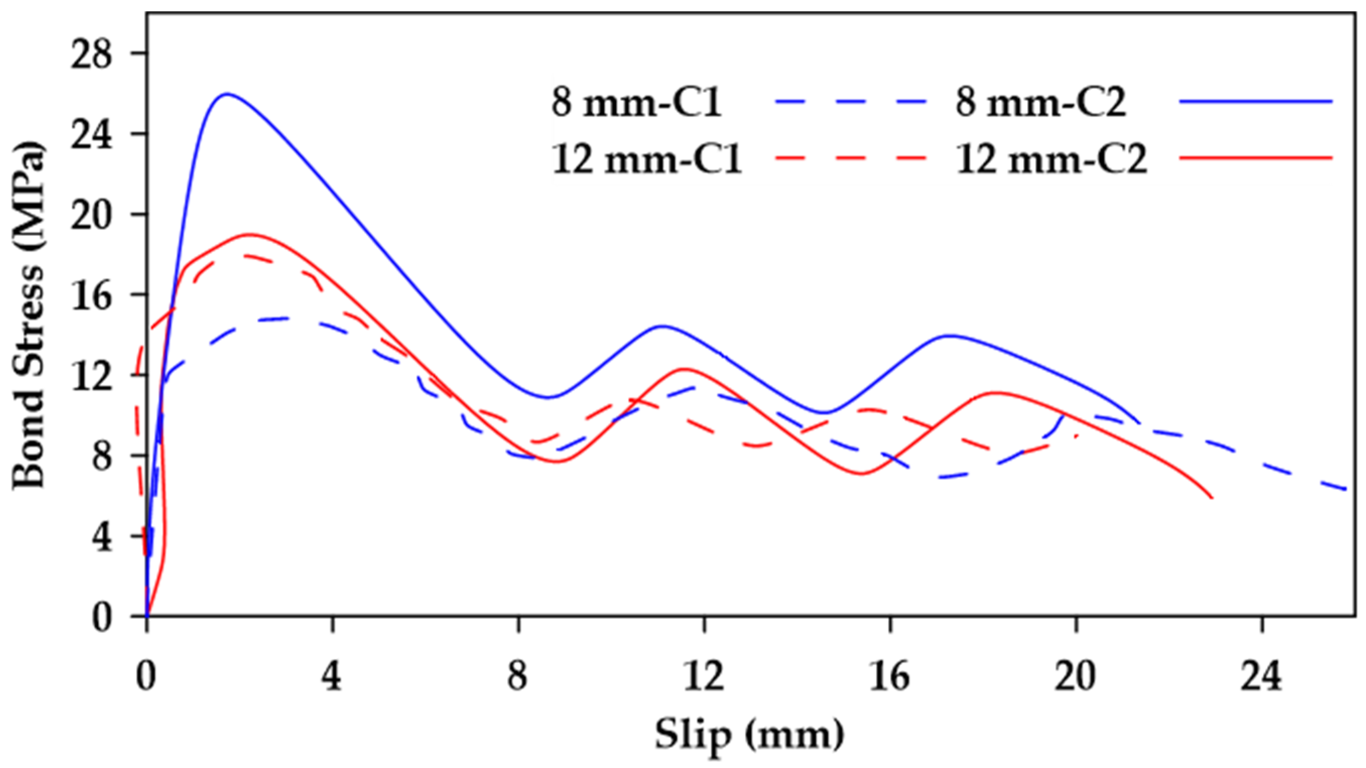
Figure 4. Moreover, it was observed that increases in concrete strength led to an increase in bond strength in specimens where bond failure occurs at the surfaces of both the bar and the concrete (i.e., ribbed bars) as shown in
Figure 5. This effect is more prominent in bars with smaller diameters. On the other hand, bond strength in specimens where failure occurred at the surface of the bar only (i.e., non-ribbed or smooth bars) was not affected by concrete strength (
Figure 6).
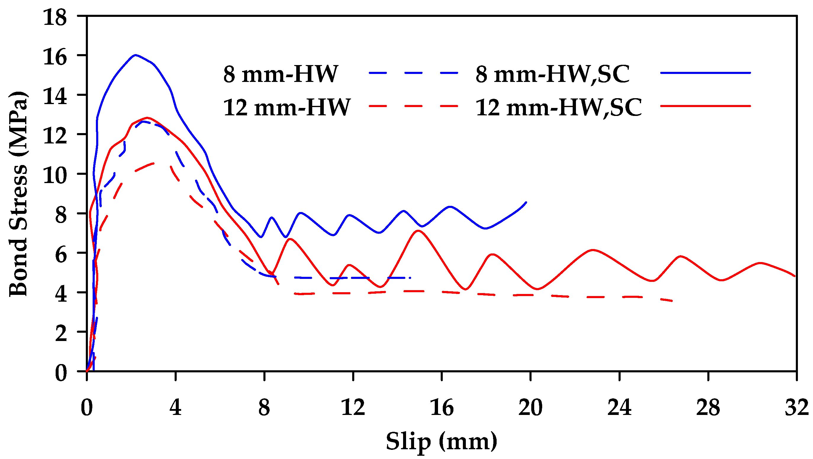
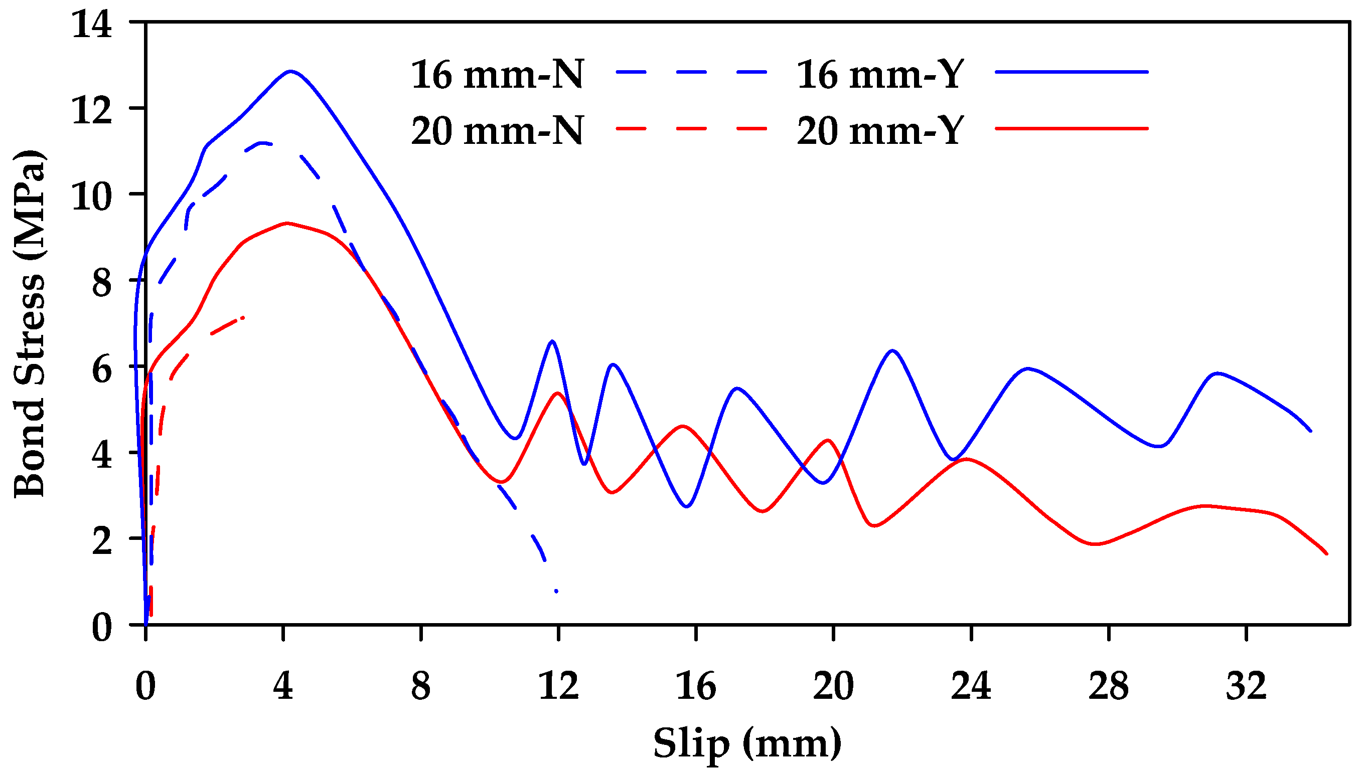
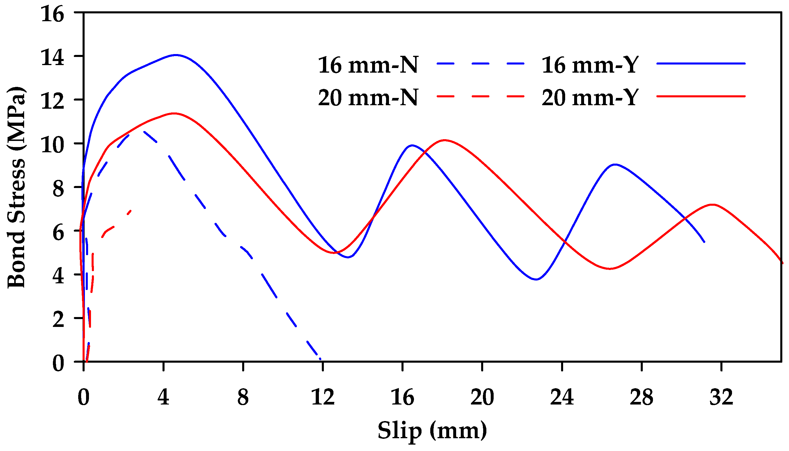
Additionally, it was concluded that surface characteristics have a significant effect on bond behavior, with ribbed bars exhibiting a higher bond strength than helical wrapped bars and sand-coated helical bars [
37]. Failure in ribbed bars occurred due to the crushing of concrete and the shearing of ribs. In contrast, the concrete surface remained intact when testing helical wrapped bars and sand-coated helical bars, with failure resulting from the detachment of the fiber spirals and resin layer in the helical wrapped bars and from the detachment of sand grains in the sand-coated bars. Furthermore, the sand-coated helical bars exhibited greater bond strength than traditional helical bars (
Figure 7). It was also found that the presence of stirrups can change the failure mode of the specimen from concrete splitting failure to pullout failure, correspondingly increasing the bond strength of the GFRP bars and improving overall bond behavior (
Figure 8 and
Figure 9).
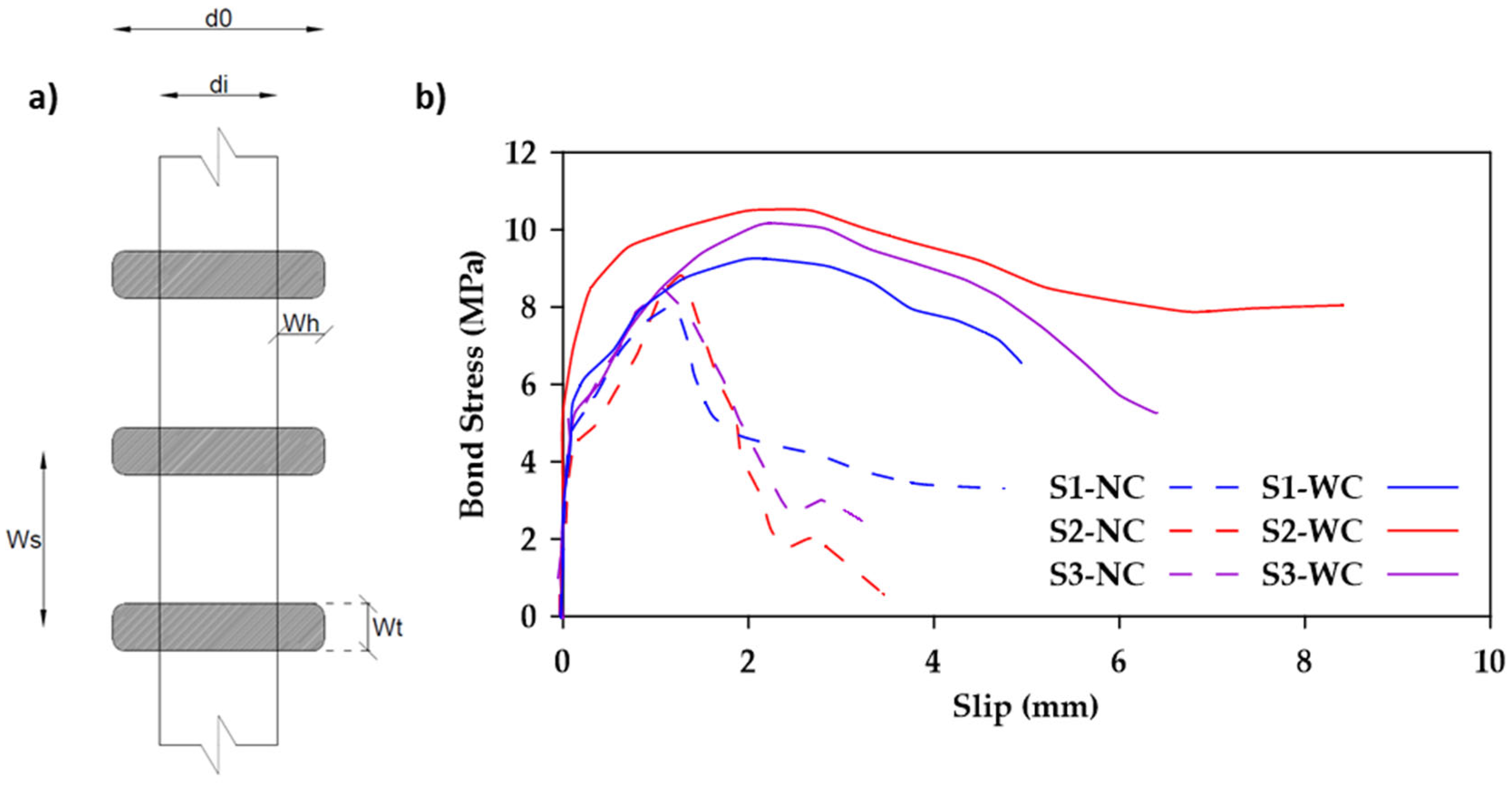
In another study, Rather et al. [
38] investigated the bond behavior of 24 GFRP-reinforced concrete specimens [
38]. The bond strength increased by up to
when the surface geometric properties of the GFRP bars were altered (i.e., winding span, winding thickness, and winding height as shown in
Figure 10). This occurs because of improved mechanical interlocks and friction mechanisms. It was also observed that the bond strength decreased as the embedment length of the GFRP rebars increased. This reduction may be attributed to the nonlinear stress distribution and the inconsistent reduction of frictional forces over the embedment length of the bar. Furthermore, the use of confining stirrups led to an increase of about 10–18% in bond strength. It was also noted that all specimens containing confining reinforcement exhibited a relatively ductile pullout failure, as shown in
Figure 10b, where the notations S1, S2, and S3 represent different bar surfaces having different combinations of winding span, winding thickness, and winding height.
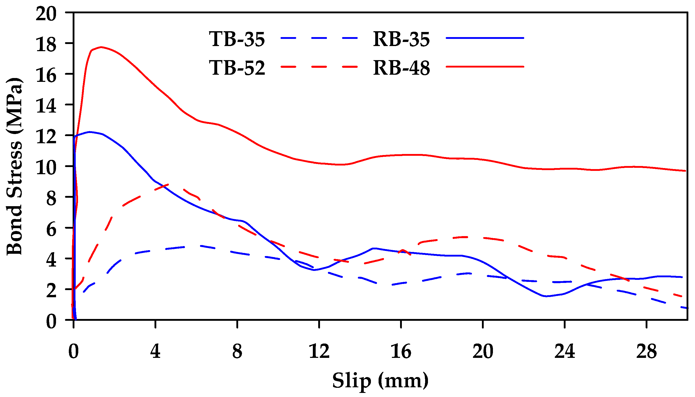
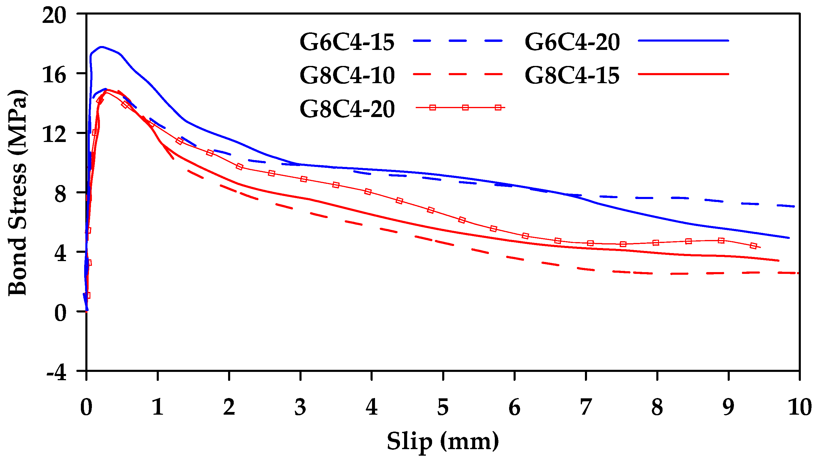
The pullout local bond stress–slip response of GFRP bars was also investigated in [
39]. The test parameters included the concrete cover, the splice length, the effect of confinement provided by stirrups, and the concrete compressive strength. The findings indicated that the presence of confining reinforcement increases the bond strength significantly for both ribbed bars, which experienced splitting failure, and thread-wrapped bars, which experienced pullout failure. Furthermore, it was concluded that increasing the width of the concrete cover has a less pronounced effect on the bond strength in GFRP bars than in steel bars of equal diameter. Increasing concrete strength led to an increase in bond strength in both types of GFRP bars, with ribbed bars having higher bond strength than threaded bars (
Figure 11).
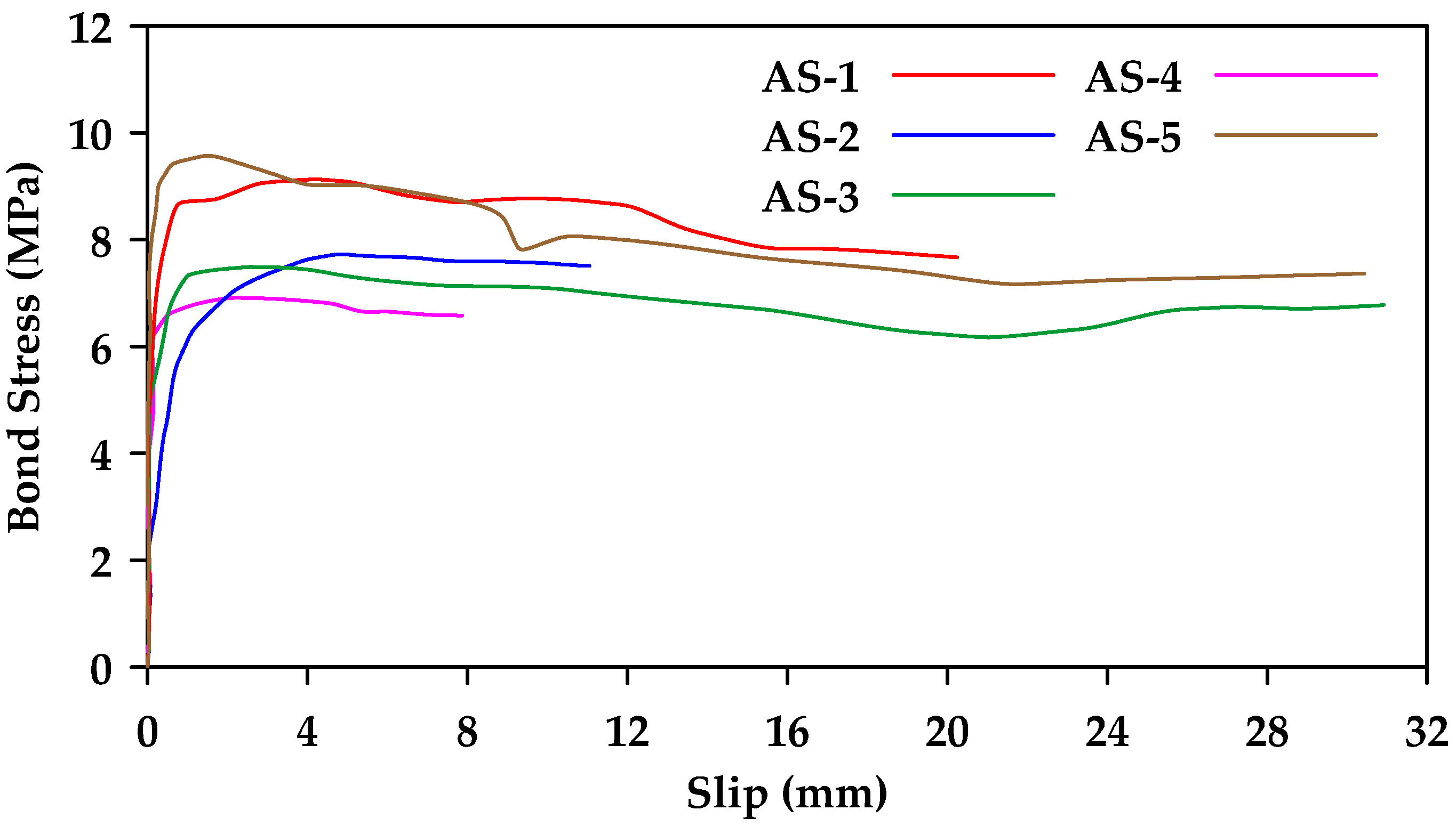
In a different study, Gooranorimi et al. [
40] performed pullout tests on GFRP bars with a nominal diameter (
of
[
40]. The bars in consideration were manufactured of helically wrapped fiber and coated with fine sand. Five different samples with an embedment length of
were investigated. All the samples experienced pullout failure with an average bond strength of
and a standard deviation of
(
Figure 12).
Ahmed et al. [
41] conducted pullout testing of
FRP (Glass and Carbon) and steel bars [
41]. The study included four different diameters of sand-coated GFRP bars (
and
). The bars were embedded in concrete with a compressive strength of
and an embedment length equal to
. All tested samples (both steel and GFRP) failed due to bar pullout. Furthermore, it was observed that the bond strength decreased with an increase in bar diameter.
Figure 13 shows the obtained bond stress–slip relationships for GFRP bars of diameter
and
(
and
respectively). The average bond strength for GFRP samples with a diameter of
and
was
and
, respectively.
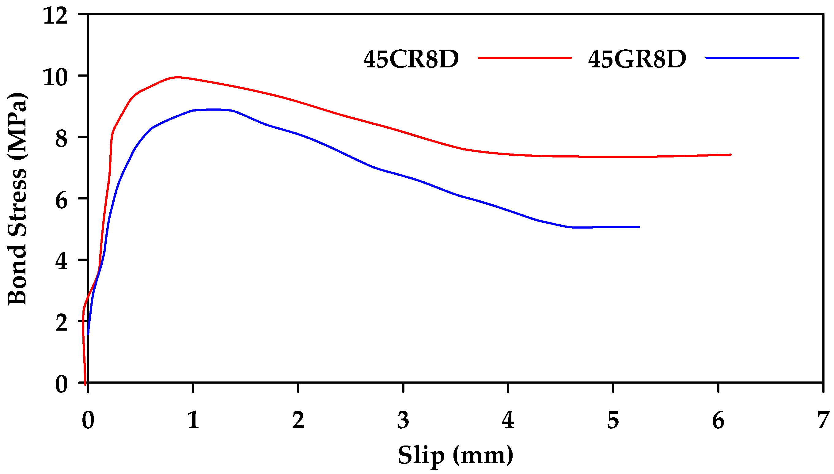
Achillides and Pilakoutas [
42] performed direct pullout tests on
specimens of concrete reinforced with different types of bars (Glass, Carbon, Aramid FRP and steel) [
42]. The main factors considered were the concrete strength, the diameter of the bar, the shape of the bar (round or square), and the embedment length.
Figure 14 shows the obtained bond stress–slip relationships for round GFRP and CFRP bars embedded in
concrete. The two bar types behave similarly, with the CFRP bars having a slightly higher bond strength than the GFRP bars. On the other hand, a significant difference was observed between the failure modes of steel and GFRP bars in concrete with strength greater than
When steel bars were tested, shear cracks developed between the bars and the concrete before pullout failure occurred. This implies that the bond strength of steel bars is highly dependent on the strength of concrete. On the other hand, the bond strength of GFRP bars was found to be independent of the concrete strength when the concrete has a strength greater than
. For concrete strength less than
, failure occurs in the concrete matrix for both steel and GFRP, and thus, the bond strength of both types of bars is dependent on the concrete strength. Additionally, the bond strength recorded in square GFRP bars was found to be about
higher than that of round GFRP bars. Another finding was that the increase in bar diameter leads to a decrease in bond strength of GFRP bars.
Veljkovic et al. [
43] compared the performance of GFRP bars and steel bars subjected to pullout tests [
43]. Two different types of GFRP bars (wrapped and ribbed) were tested. The effects of the concrete material properties and the concrete cover were also considered. The results indicated that sanded and spirally wrapped GFRP bars have brittle bond behavior, while ribbed GFRP bars behave in a manner similar to steel bars. Furthermore, ribbed GFRP bars have higher bar slips for maximum value of bond stress, compared to sanded and wrapped bars, but slightly smaller values compared to steel. It was also found that the bond strength of ribbed GFRP bars is dependent on the concrete mechanical strength. The material properties of concrete with average compressive strength between
and
do not significantly affect the bond strength. On the other hand, the bond strength is significantly enhanced when GFRP bars are embedded in concrete with an average compressive strength within the range of 40–65 MPa. Additionally, it was observed that increasing the concrete cover can lead to a decrease in bond strength of ribbed GFRP bars embedded in concrete with low compressive strength and can cause a change in the failure mode from direct concrete splitting to crushing of concrete. On the other hand, this effect is reversed as concrete strength increases (as shown in
Figure 15). Furthermore, in cases of concrete with high compressive strength, the effect of concrete cover decreases as the bar diameter increases (
Figure 15). For optimal benefits, it was recommended that ribbed GFRP bars be used in conjunction with mid-strength concrete (
) and a low concrete cover to produce a high bond strength and delay cover cracking.
Benmokrane and Tighiouart [
44] studied the bond strength of GFRP and steel bars by conducting beam tests on 20 concrete beams reinforced with four nominal diameters from
to
[
44]. The findings confirmed that the bond strength of GFRP bars decreases with an increase in bar diameter. The reported bond strength of GFRP reinforcing bars was lower than that of steel reinforcing bars, depending on reinforcing bar diameter, as shown in
Figure 16.
In another study, Tastani and Pantazopoulou [
32] investigated the local bond mechanics of glass fiber-reinforced GFRP bars in normal-strength concrete by conducting 30 direct pullout tests on GFRP bars [
32]. The study considered the impact of the bar surface and bar diameter. The two types of GFRP bars investigated were Aslan100 and Fiberglass CPP rebars, with the main difference between the two being in their surface pattern. The Aslan bars were sand coated with helical lengthwise indentations, while the CPP bars were sand coated only. The diameter considered for each type of bar were
and
. The results for the CPP bars showed that the bond strength decreases with an increase in bar diameter, as has been observed from previous tests. However, the results for the Aslan100 bars indicated that the bar diameter has minimal effect on bond strength in this type of bar surface. The authors attributed this to the fact that Aslan100 bars of different sizes had varying surface indentation, which altered bond conditions between bars of different diameters.
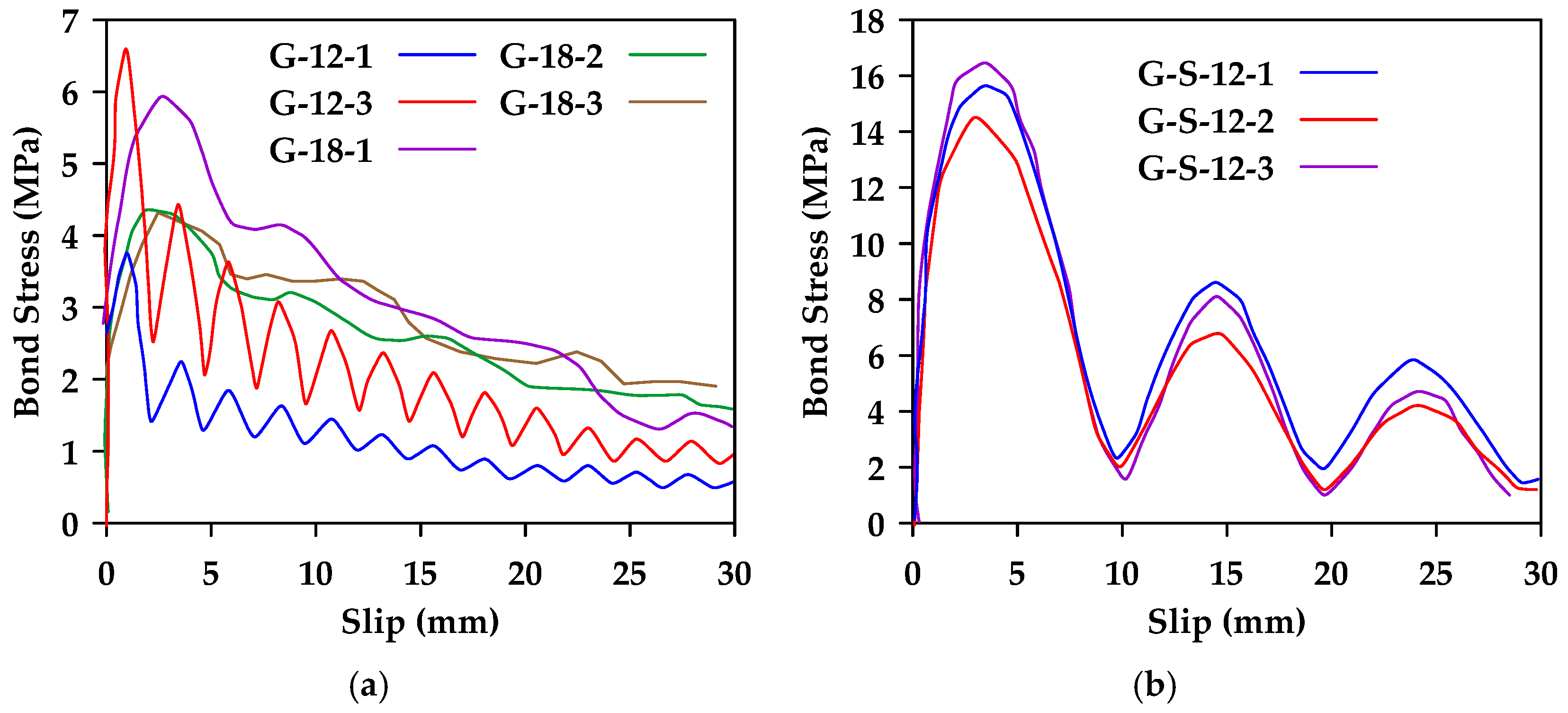
Chen et al. [
45] conducted pullout tests on three types of bars (steel bars, glass fiber-reinforced polymer (GFRP) bars, and basalt fiber-reinforced polymer (BFRP) bars) with different surface conditions (smooth and ribbed for steel bars and smooth, shallow ribbed, and deep ribbed for BFRP bars and GFRP bars) [
45]. Two bar diameters (
and
) were considered. The authors observed that all GFRP bars with no or shallow ribs with a diameter of
exhibited pullout failure. The
smooth GFRP bars also exhibited pullout failure. On the other hand,
GFRP bars with shallow and deep ridges and the
GFRP bars with deep ridges exhibited premature splitting failure.
Figure 17 shows the results obtained for smooth and shallow ribbed GFRP bars of different diameters. It was also concluded in this study that rib height has a great influence on bond behavior, and bond strength is increased with larger rib height.
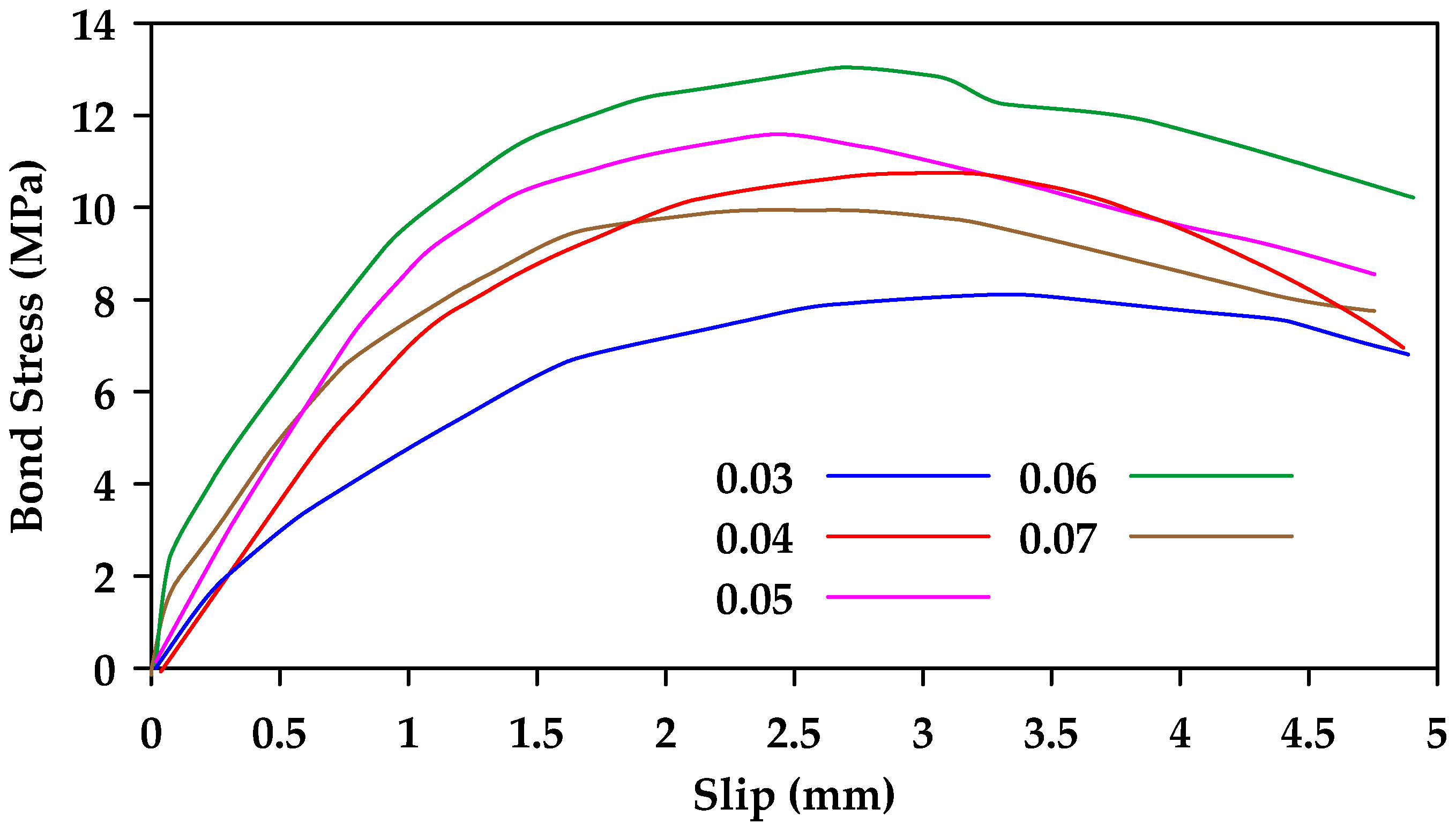
Hao et al. [
46] performed pullout tests on 30 types of GFRP bars with different rib geometries to investigate the effect of rib height and rib spacing [
46]. When rib spacing was kept constant, the bond strength of ribbed rebars with a rib height equal to
of the rebar diameter was superior (
Figure 18). On the other hand, when rib height was constant, the bond strength of ribbed rebars with a rib spacing equal to the rebar diameter was superior. Thus, the optimal combination was having a rib spacing equal to the rebar diameter and a rib height equal to
of that value.
In addition to the aforementioned studies, both pullout and bending tests were performed on GFRP bars and steel bars embedded in concrete in [
47]. Furthermore, Wu et al. [
48] performed lap splice beam tests to determine the effect of stirrups spacing on bond behavior of GFRP bars [
48]. As expected, it was determined that decreasing bond spacing leads to an increase in bond strength, particularly in bars with a smaller diameter. Abbas et al. [
49] also investigated the effect of lap splicing and stirrups spacing on GFRP bar bond [
49]. Zhao et al. [
50] compared the bond behavior of GFRP bars and the bond behavior of CFRP and steel bars through pullout testing [
50]. Vint [
51] concluded that the surface profile of GFRP bars can significantly influence the post-peak phase of the bond stress–slip curve [
51]. Solyom and Balázs [
52] investigated the bond behavior of GFRP bars with different surface configurations. The configurations studied included helically wrapped, sand coated, helically wrapped and sand coated, indented, and ribbed surfaces. The findings indicated significant differences in the bond strength obtained between bars of different surfaces. Moreover, significant differences were also observed between bars of the same surface category (e.g., varying sand fineness within the sand-coated surface category) [
52]. Other experimental studies on the bond behavior of GFRP bars embedded in concrete and the parameters that affect it include [
53,
54,
55,
56,
57,
58,
59,
60,
61,
62,
63,
64,
65].
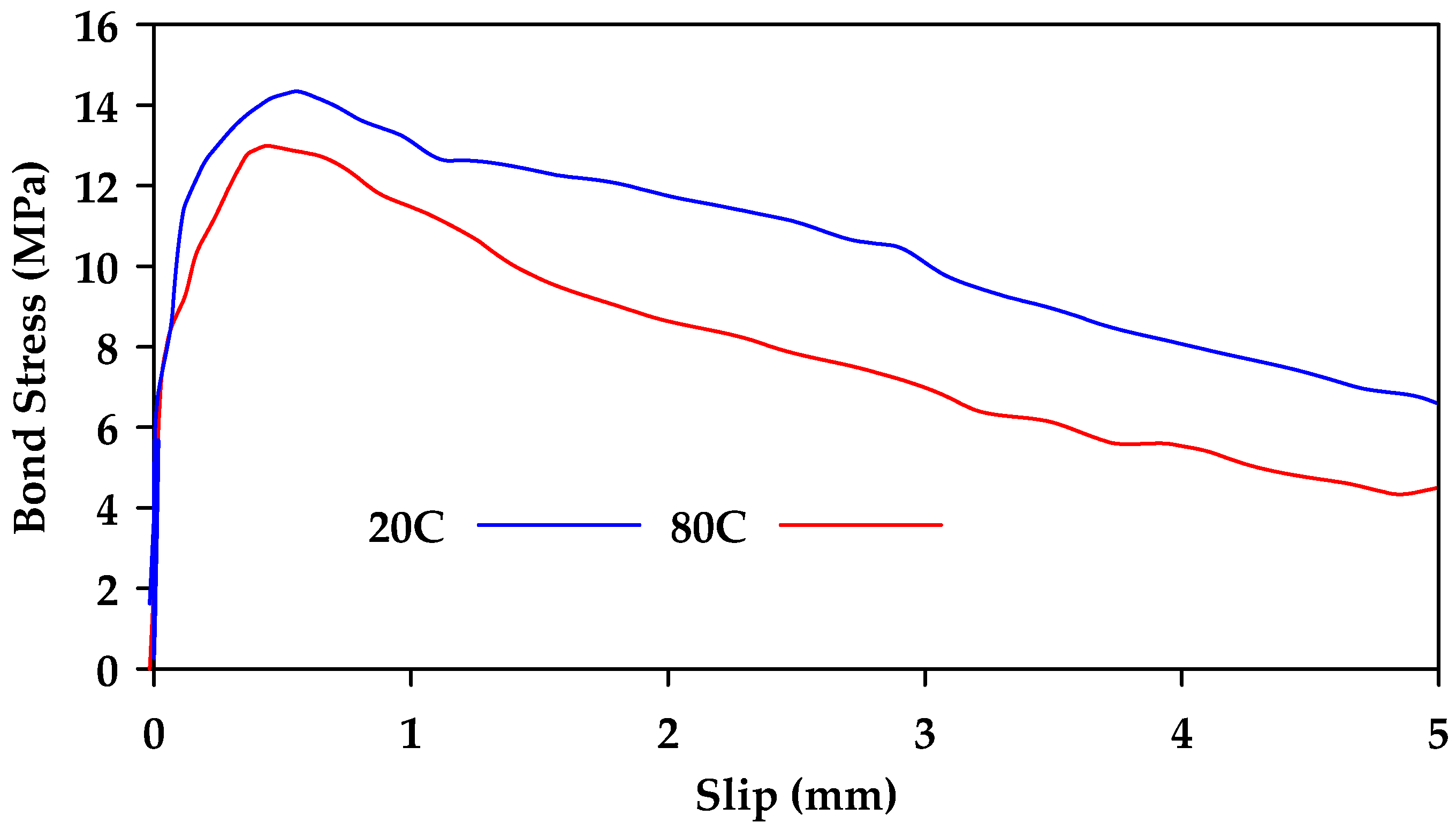
The effect of elevated temperatures on the bond strength of GFRP bars embedded in concrete has also been studied. In [
66], it was determined that regardless of surface texture, elevated temperatures significantly influence the bond strength. Initially, the strength loss observed in GFRP bars due to increased temperatures is similar to the bond loss observed in steel bars. However, as temperatures increased beyond
, a significant loss in bond strength was observed with a reduction of about
in strength at a temperature of
as shown in
Figure 19 where the notation CB refers to GFRP bars with molded deformations on the surface, similar to ordinary deformed steel rebars, with a smooth surface between deformations and the notation CPI refers to GFRP bars that contain wraps of a wide braid of fibers on the surface. Similar findings were also reported in [
67], where it was found that the bond strength measured at
was reduced by 80–90% when the temperature increased to
. In another study, Masmoudi et al. [
68] subjected a total of 80 specimens to four different temperatures (20, 40, 60, and 80 °C) for four and eight months [
68]. Two different bar diameters were investigated
and
). Minimal effect was observed as temperatures increased from
to
. However, as temperatures increased to
, the maximum pullout load decreased by up to
(
Figure 20). Hajiloo and Green [
69] also performed pullout tests on sand-coated and ribbed GFRP bars for a temperature range of 25 °C–360 °C [
69]. It was determined that the bond strength significantly decreased as temperature increased, with a maximum of
retained strength at temperatures above
regardless of bar surface. Mousavi et al. [
70] investigated the effectiveness of longer embedment lengths on bond degradation due to temperature [
70]. It was determined that the increase in embedment length led to improved pullout capacity under elevated temperatures [
70].
Ellis et al. [
71] observed that
of the original bond strength was retained once GFRP bars cooled down to room temperature after being exposed to temperatures of
[
71]. Hamad et al. [
72] found that the bond strength of 10 mm GFRP bars was reduced by
when exposed to temperatures of
[
72]. Özkal et al. [
73] reported that steel bars retained
of their bond to concrete at an elevated temperature of 600 °F, while GFRP bars only retained
of their bond strength at the same temperature [
73]. It is noted, however, that the tested specimens were of different diameters (
for the steel bars and
for the GFRP bars). Solymon et al. [
74] also performed pullout tests on indented GFRP bars embedded in concrete and exposed to temperature ranges of
to
[
74]. All specimens failed due to bar pullout regardless of temperature, and it was concluded that bond strength decreases with temperature, with a reduction of
in bond strength observed at a temperature of
. In addition, it was concluded that the reduction of bond strength with temperature is also affected by the reduction of concrete strength and elasticity with temperature. Furthermore, the effect of effect of bond degradation at elevated temperature on structural performance of GFRP-reinforced concrete structures was also studied in [
75,
76,
77,
78].
Ruiz Emparanza et al. [
79] investigated the bond behavior between GFRP bars and concrete in marine environments [
79]. In this study, pullout tests were performed on GFRP bars subjected to different temperatures (
and
) and exposed to seawater for 60 and 120 days. The results show that the bond behavior is independent of the duration of exposure and bond deterioration was not observed throughout the testing period. The resistance of GFRP bars to aggressive environments was also confirmed by pullout tests conducted in [
80]. In those tests, the GFRP bars were exposed to twelve different harsh environments. Alves et al. [
81] investigated the effect of freeze-thaw cycles and fatigue loading on the bond behavior of GFRP bars [
81]. It was determined that fatigue load can reduce the bond strength by about
while freeze-thaw cycles can improve the bond to concrete by about
. Abed and El Mesalami [
82] concluded that the bond between GFRP bars and concrete is minimally affected by exposure to direct sunlight and seawater [
82]. The resistance of the bond between GFRP bars and concrete to aggressive environments (such as alkaline solutions, acid solutions, and salt solutions) was also confirmed in [
80,
83,
84,
85,
86,
87,
88,
89,
90,
91]. Furthermore, Robert and Benmokrane [
92] concluded that aging has a minimal effect on the durability of the GFRP bar–concrete interface [
92].
Several attempts have been made to investigate the bond stress–slip relationships of GFRP bars to different types of concrete. Saleh et al. [
93] performed hinged beam tests on 28 specimens of GFRP bars embedded in high-strength concrete [
93]. Most of the tested specimens failed due to the pullout of the GFRP bar. Additionally, it was determined that bond strength reduces with an increase in embedment length and bar diameter. The bond characteristics of GFRP bars in high-strength concrete were also investigated in [
94]. Hossain et al. [
95] performed pullout tests on GFRP bars embedded in ultra-high-strength concrete [
95]. Hu et al. [
96] investigated the bond behavior of sand-coated GFRP bars embedded in different types of concrete (Ultra-High-Performance Concrete (UHPC) and High-Performance Concrete (HPC)) [
96]. The findings indicated that GFRP bars embedded in UHPC showed an increase of about
and
in bond strengths when compared against GFRP bars embedded in HPC and normal concrete, respectively. Furthermore, it was found in [
97] that the reduction rate of bond strength of GFRP bars with increasing bar diameter and embedment length was reduced in high-strength concrete when compared against GFRP bars embedded in normal concrete. Luo et al. [
98] investigated the effect of bar diameter on the bond of ribbed GFRP bars embedded in UHPC and determined that the bond initially increases with an increase in bar diameter up to a certain limit (
above, which the bond strength decreases with increased diameter [
98]. Lu et al. [
99] found that sand-coated bars exhibited better bond behavior than ribbed bars when embedded in high-performance concrete [
99]. Tong et al. [
100] also investigated the bond behavior of GFRP bars in UHPC [
100]. In another study, it was determined that the use of seawater sea-sand ultra-high-strength concrete instead of freshwater river-sand concrete has minimal effect on the bond strength of GFRP bars [
101]. Other studies have been performed to determine the bond behavior of GFRP bars in self-compacting concrete [
102,
103,
104,
105]. Furthermore, Romanazzi et al. [
106] determined that the bond strength of sand-coated GFRP bars increased by
when embedded in geopolymer concrete rather than ordinary Portland cement [
106]. Other studies on bond behavior of GFRP bars embedded in geopolymer concrete were conducted in [
107,
108]. Doostmohamadi et al. [
109] investigated the effect of different types of concrete (lightweight concrete and lightweight fiber-reinforced concrete) on the bond of GFRP bars [
109]. The bond behavior of GFRP bars in coral concrete has also been investigated in [
110,
111,
112].
Kim et al. [
113] investigated the effect of using structural fibers on the bond between GFRP bars and concrete by performing pullout tests on cubic concrete specimens reinforced with GFRP bars [
113]. The main differences between the specimens were in the fiber type (steel, PVA, and PP), the fiber volume fraction, and the GFRP bar surface (sand coated and helically wrapped). It was found that the use of structural fibers leads to an increase in bond strength as well as a delay in the pullout failure of the bars. Moreover, the addition of structural fibers changed the failure modes for GFRP bars. The authors recommended the use of different volume fractions and different types of structural fibers for different types of bars:
steel fibers for sand-coated GFRP rebar (
Figure 21) and
PVA fibers for helically wrapped GFRP rebar. Haung et al. [
114] investigated the bond behavior of GFRP bars embedded in fiber-reinforced concrete containing three different types of artificial fibers (carbon, aramid and polypropylene) [
114]. It was concluded that the bond behavior of GFRP bars was significantly improved when embedded in concrete containing fibers as opposed to ordinary concrete. Won et al. [
115] studied the bond behavior of GFRP bars embedded in high-strength concrete containing varying amounts of steel and synthetic fibers [
115]. The obtained bond strength between the FRP reinforcing bar and the concrete increased by 5–70% as the volume fraction of fiber increased [
115].
Ashrafi et al. [
116] investigated the use of carbon fiber mat anchorage to improve the bond behavior of GFRP bars [
116]. The bond strength increased by up to
when the anchorage system was used efficiently (i.e., in specimens where confinement strength was sufficient). Rahimi et al. [
117] found that using steel anchors can improve the bond strength of GFRP bars to concrete by up to
depending on the concrete compressive strength, bar diameter, and geometry of the steel anchor [
117]. Shakiba et al. [
118] found that the shape of the anchor head is found to be a key parameter in the bond performance of anchored GFRP bars [
118]. Islam et al. [
119] determined that headed-end GFRP bars showed improved bond strength in comparison with straight-end GFRP bars [
119].
3. Analytical Models
Several analytical models that capture bond stress–slip relationships between concrete and FRP bars have been proposed. One such model was proposed in a study conducted by Malvar [
120]. In this study, a large array of experimental pullout tests was conducted on GFRP bars. The authors proposed an analytical model for the bond–slip–stress relationship based on their experimental findings. The model, expressed in terms of the bond slip
and the bond stress (
, can be expressed as shown in Equation (2a–c).
The empirical constants
and
are a function of the bar type under consideration.
is the tensile strength of concrete,
is the peak bond stress,
is the slip corresponding to the peak bond stress, and
is the confining axisymmetric radial pressure. It is noted that this study neglected the effect of bar diameter. Another limiting factor is the difficulty of determining the value of
for members subjected to bending. Furthermore, Malvar’s Model was assessed as being unreliable for modelling the ascending branch of the bond stress–slip relation curve [
121].
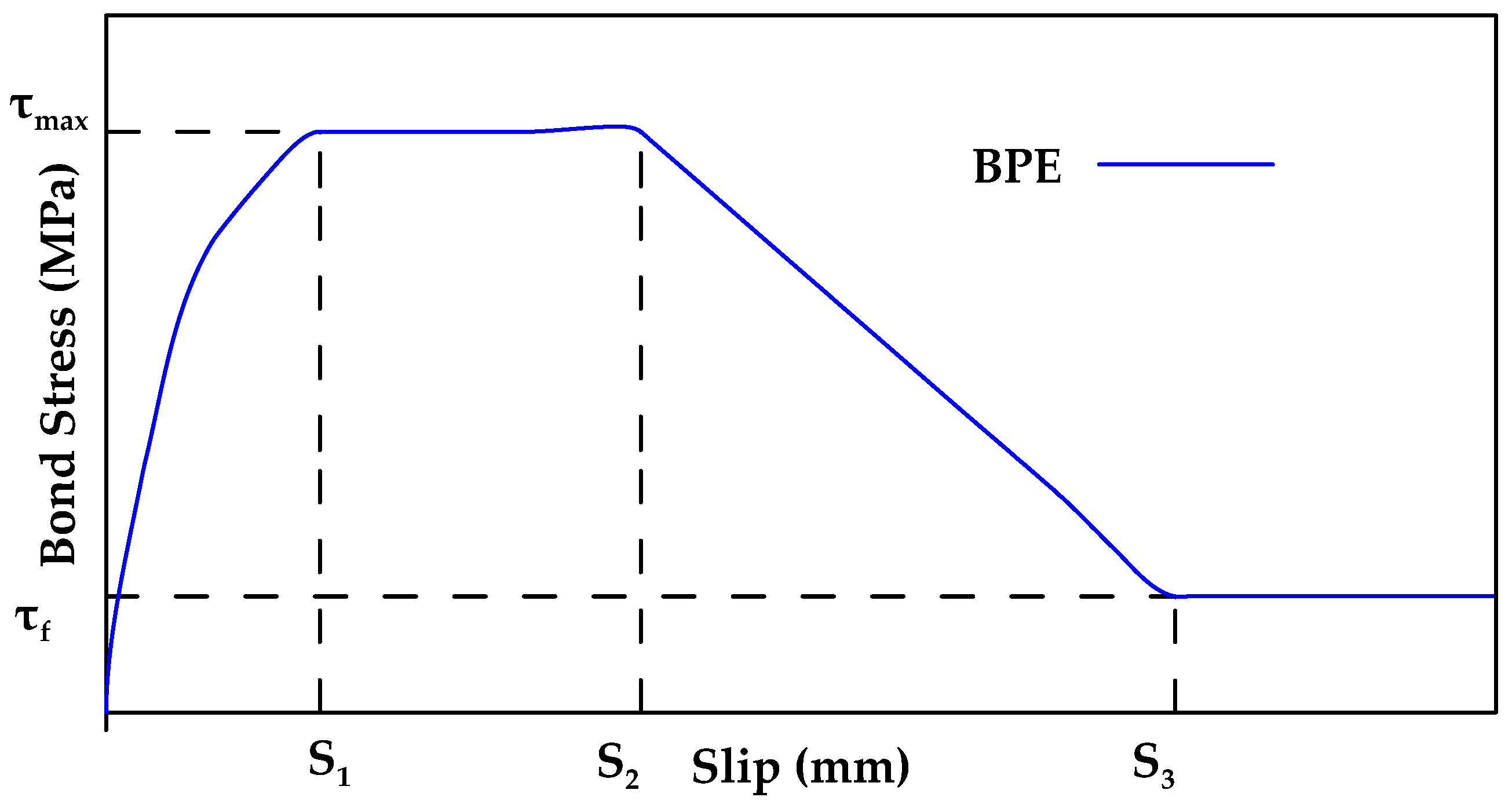
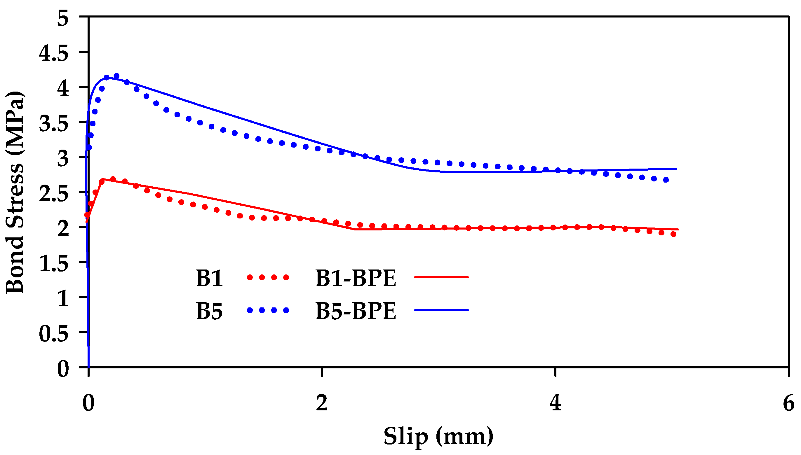
The BPE model is another model used to describe the bond behavior of FRP bars to concrete [
122]. The BPE model comprises an ascending branch, two regions of constant bond stress, and a descending branch as shown in
Figure 22. Initially, bond stress increases until the peak bond stress value
is reached. This ascending branch corresponds to the chemical adhesion between the bar and concrete, as well as the bearing force. After this point, the bond stress value remains constant while the slip value increases from
to
. Once point
is reached, cracks (or even crushing) start to form in the concrete and the bearing force due to mechanical interlocking diminishes, causing the bond stress to decrease linearly until it reaches point
. Afterwards, the bond stress remains constant due to friction with an increase in slip until failure. In this stage, significant cracking will occur in the concrete [
122]. The BPE model can be described mathematically as shown in Equation (3a–d).
In Equation (3a–d), the parameters (
and
) can be determined using experimental calibration. While the BPE model was designed for steel bars, it has been calibrated for use in FRP bars by [
123]. However, even though there was some correspondence between the model and experimental results, several inaccuracies were also identified, particularly in the descending branch. Furthermore, the results obtained were scattered and did not account for bar diameter.
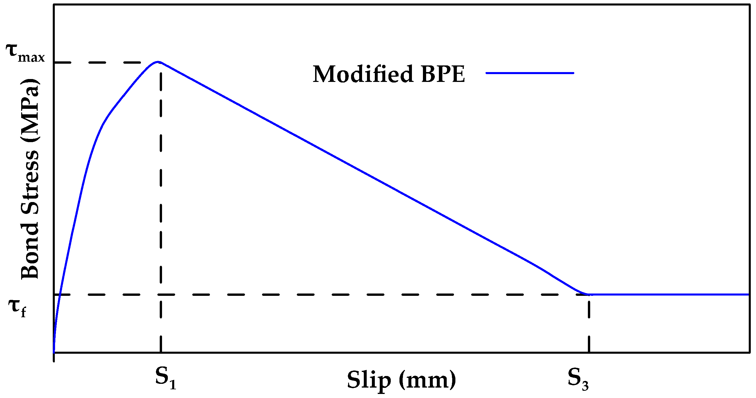
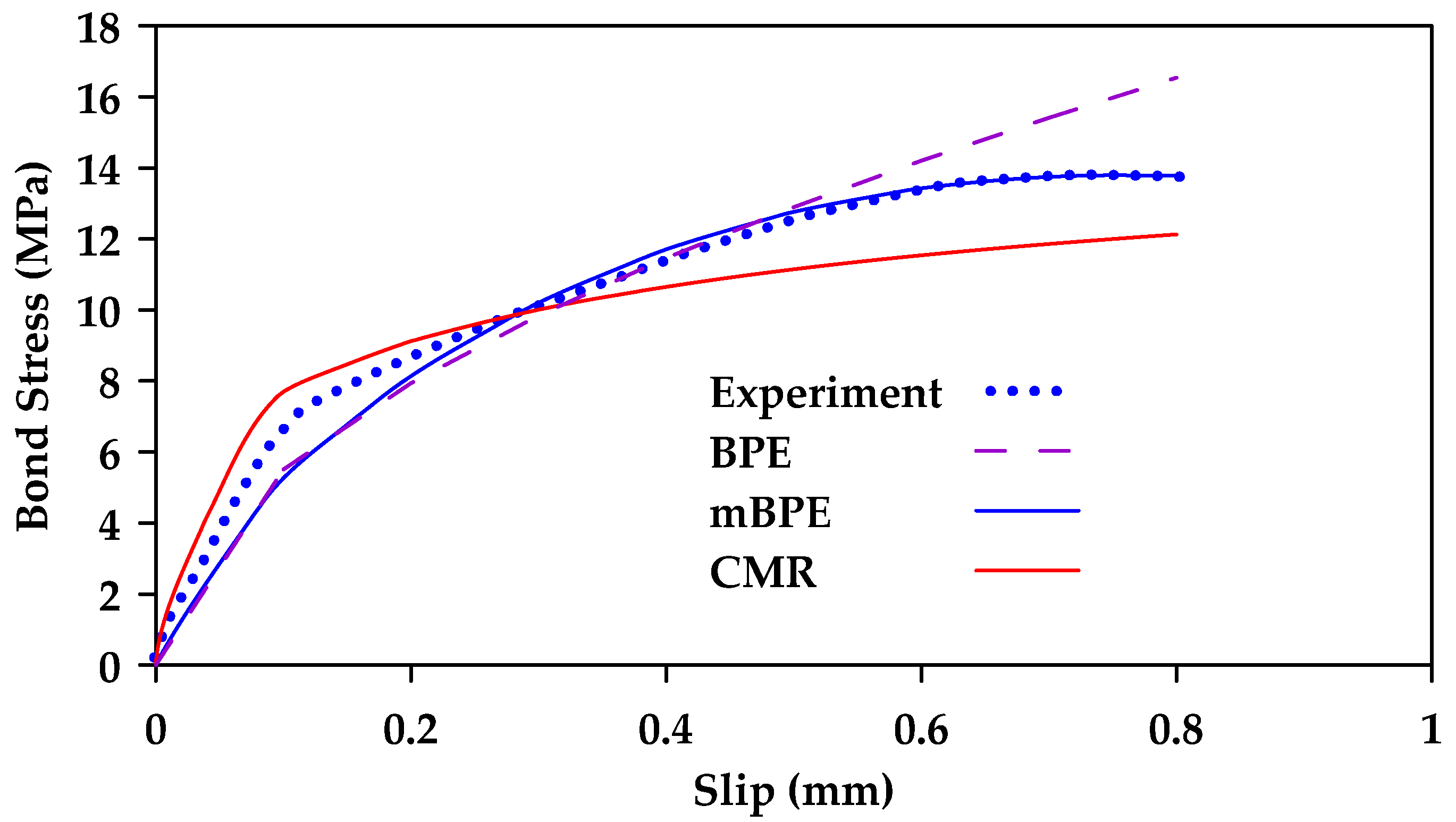
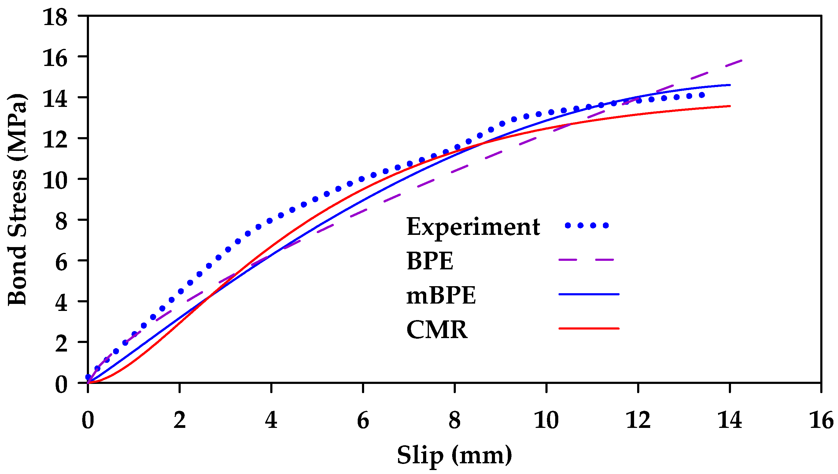
Cosenza et al. [
124] proposed a modification to the BPE model [
124]. In the modified BPE (mBPE) model (
Figure 23), the equations for the ascending branch are identical to the corresponding equations in the BPE model and only the descending branch equations are altered. The modified BPE (mBPE) model can be described mathematically as shown in Equation (4a–c). In the modified BPE model, only three parameters need to be estimated or calibrated:
and
.
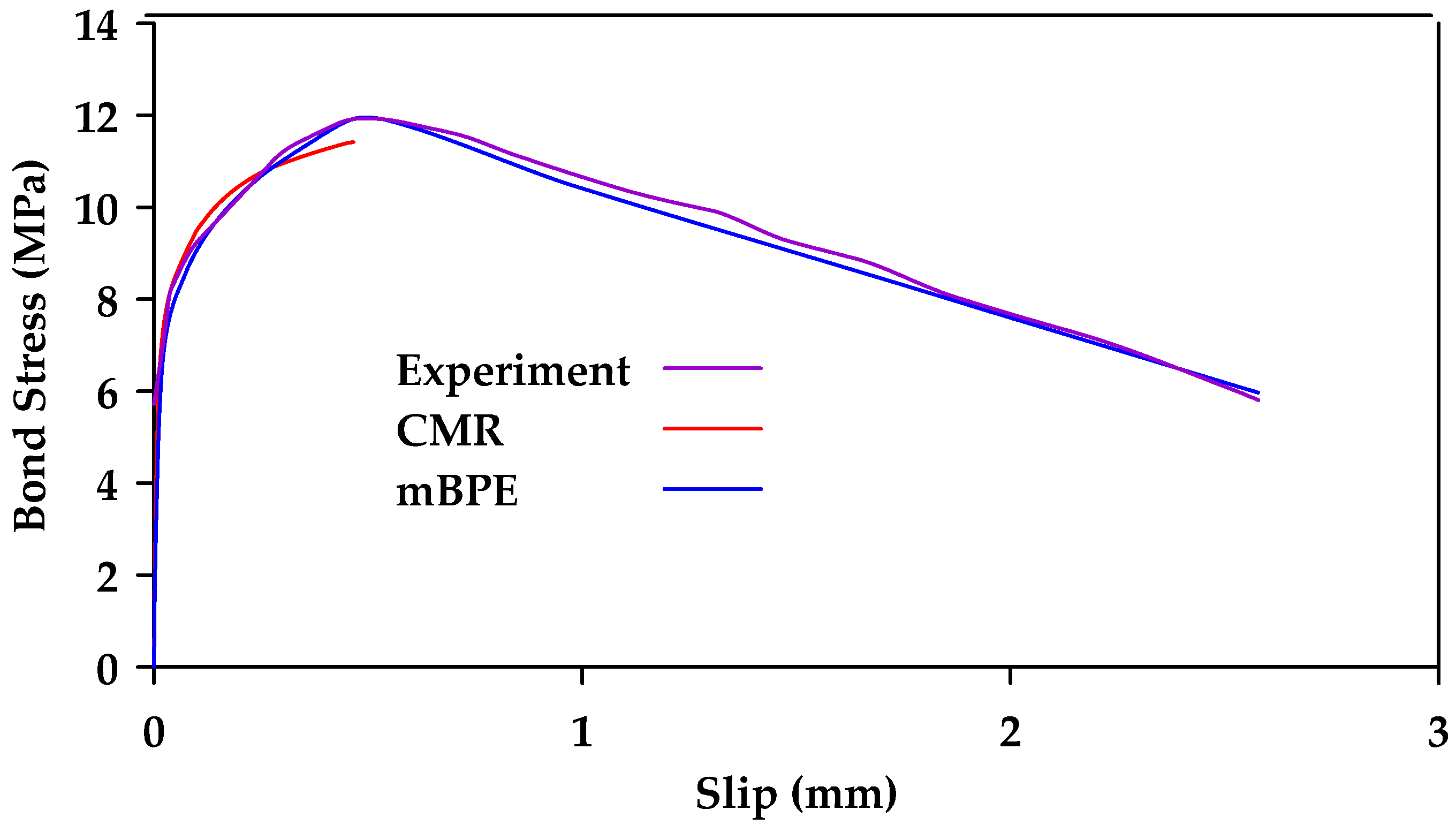
Cosenza et al. [
125] also proposed a modified ascending branch of the bond–slip–stress relationship [
125]. The modified ascending branch provides an initial slope equal to infinity and thus accounts for the physical process of adhesion more accurately. The new proposed model is referred to as the CMR model can be expressed as shown in Equation (5). The parameter
is an empirical constant determined based on the curve fitting of test data. Note that despite the attempts made to improve the analytical models, none of the models described up to this point consider the bar diameter or surface, which are a major factor in the bond–slip–stress relationship.
An alternative modification for the ascending branch was proposed in [
53]. In this alternative modification, the bond–slip–stress relationship can be expressed as shown in Equation (6). It should be noted that both the CMR model and the model proposed by [
53] are not suitable for design at ultimate limit states as they only account for the ascending branch.
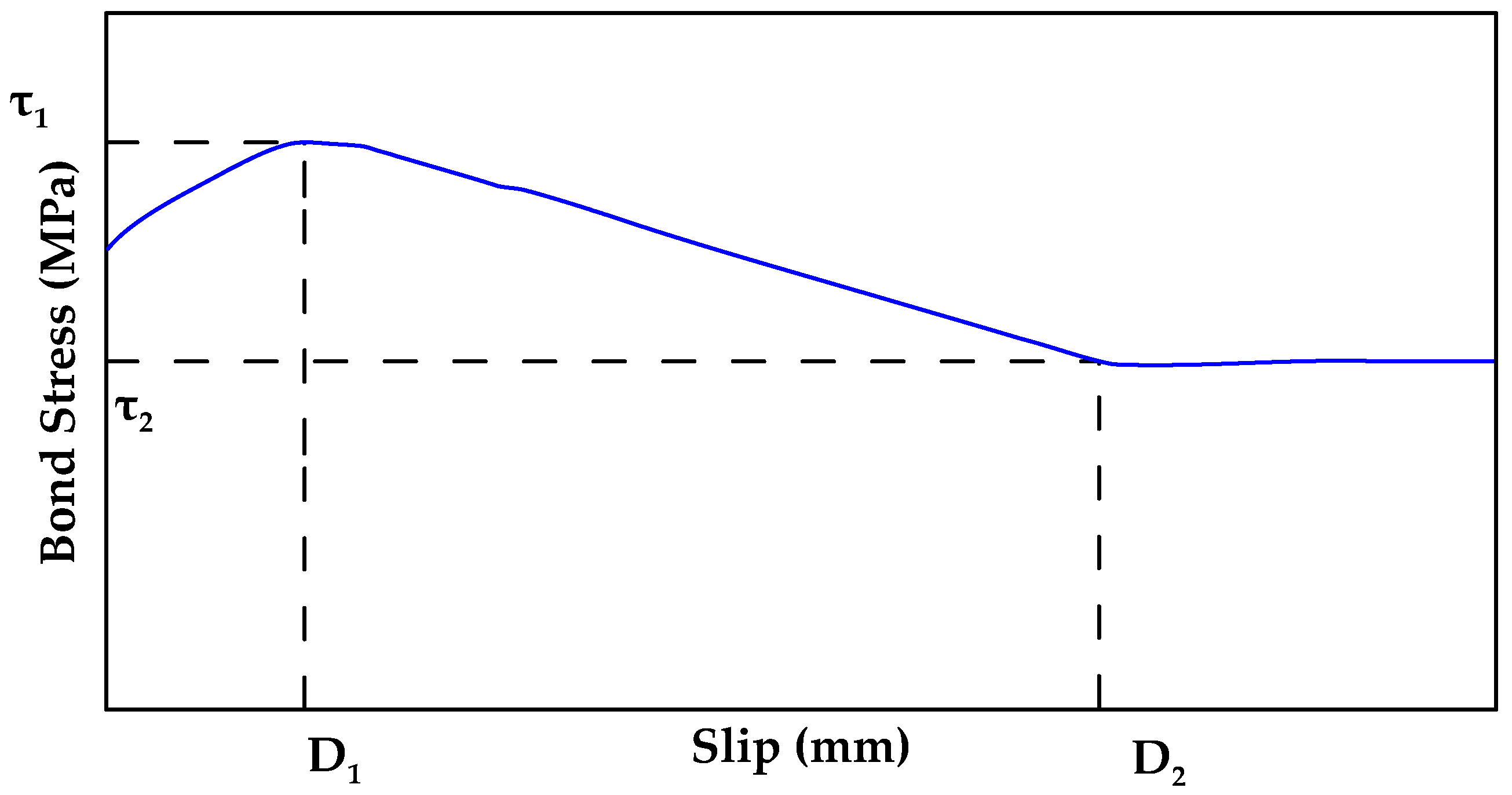
Another full model was proposed in [
40]. The proposed model consists of three stages and five parameters as shown in
Figure 24. In this model,
represents the bond stress and
represents the corresponding slip at any point. In the first stage, the bond stress exponentially increases to the peak value of
at the slip level of
as per Equation (7) (
is the exponential parameter). After the bond stress reaches the maximum value of
, it linearly decreases to
where the slip reaches
as per Equation (8).
Finally, in the last stage, the bond stress remains constant (
). It is noted that the model still requires calibration based on experimental results. For example, Gooranorimi et al. [
40] proposed the following values for the model parameters for a
helically wrapped, sand-coated GFRP bar:
,
,
, and
[
40]. This model also does not explicitly account for factors such as bar type, size and coating influence the bond–slip–stress relationship.
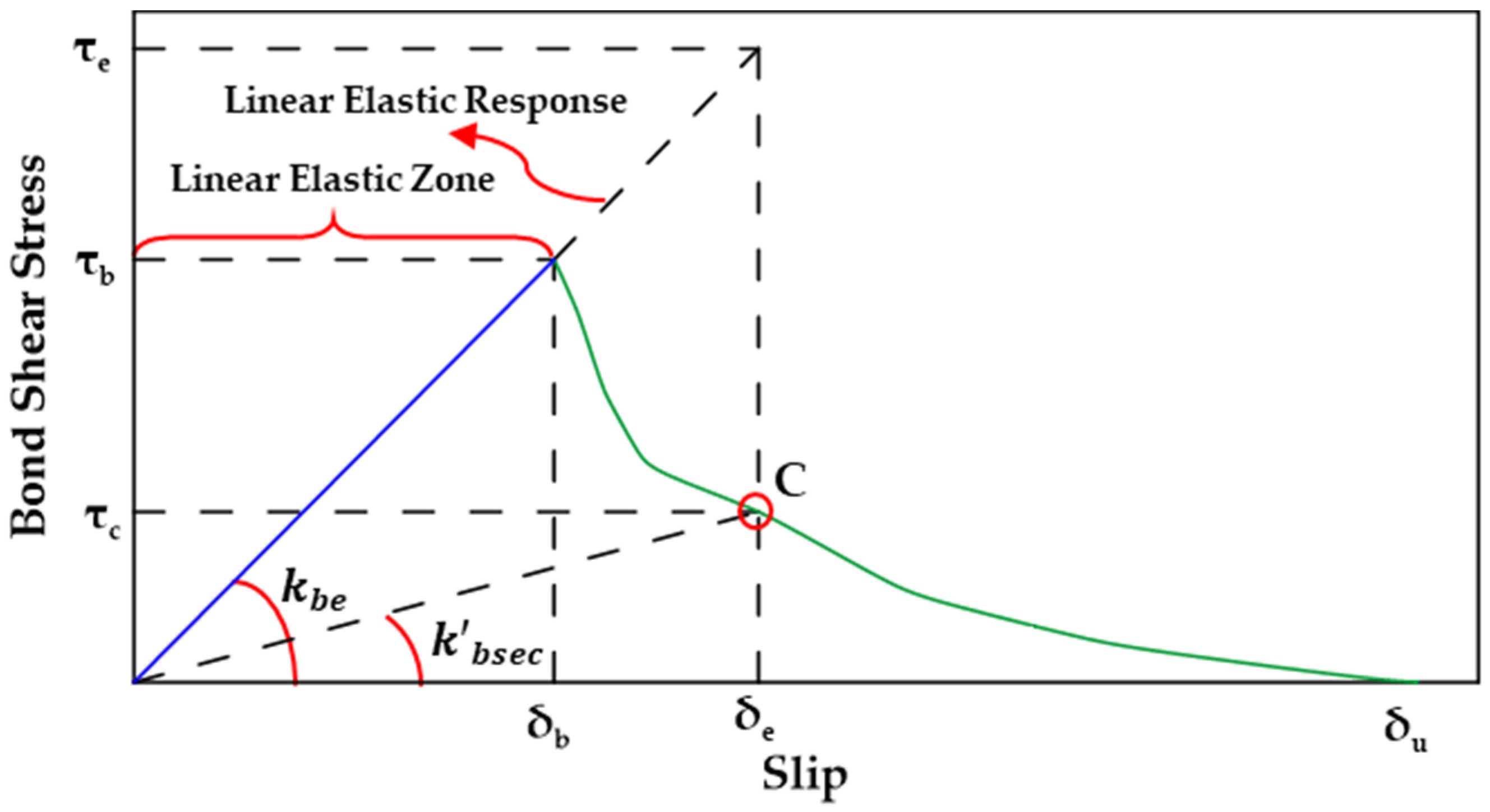
Rezazadeh et al. [
126] compared two damage-based approaches for assessing the damage evolution of the GFRP bar–concrete bond [
126]. One approach was based on the secant modulus model for assessing GFRP bond behavior as developed in [
127] while the other approach was based on the exponential damage model developed with the aim of accounting for the interface deterioration of the GFRP–concrete bond. Both approaches involve defining a scalar damage evolution variable
. The value
evolves from
at damage initiation to
at failure. In both models, a linear elastic zone, in which no damage occurs
, is defined. In this zone, the bond stress increases linearly with the increase in slip. Once the maximum bond stress value
is reached at a slip value equal to
, the bond–slip–stress relation is now considered to be in the damaged zone. The two approaches can be quantified as shown in Equation (9a–c).
In Equation (9a–c),
is the bond stress component predicted by the elastic bond stress–slip relationship without damage and
is the elastic bond stiffness. The value of
can be determined as
. The main difference between the two approaches is in the expression used to define the scalar damage variable
In the secant modulus-based damage model, the value of
can be determined in accordance with Equation (10a,b). The secant bond stiffnes
should be determined based on calibration with experimental results.
Figure 25 shows a schematic representation of the model.
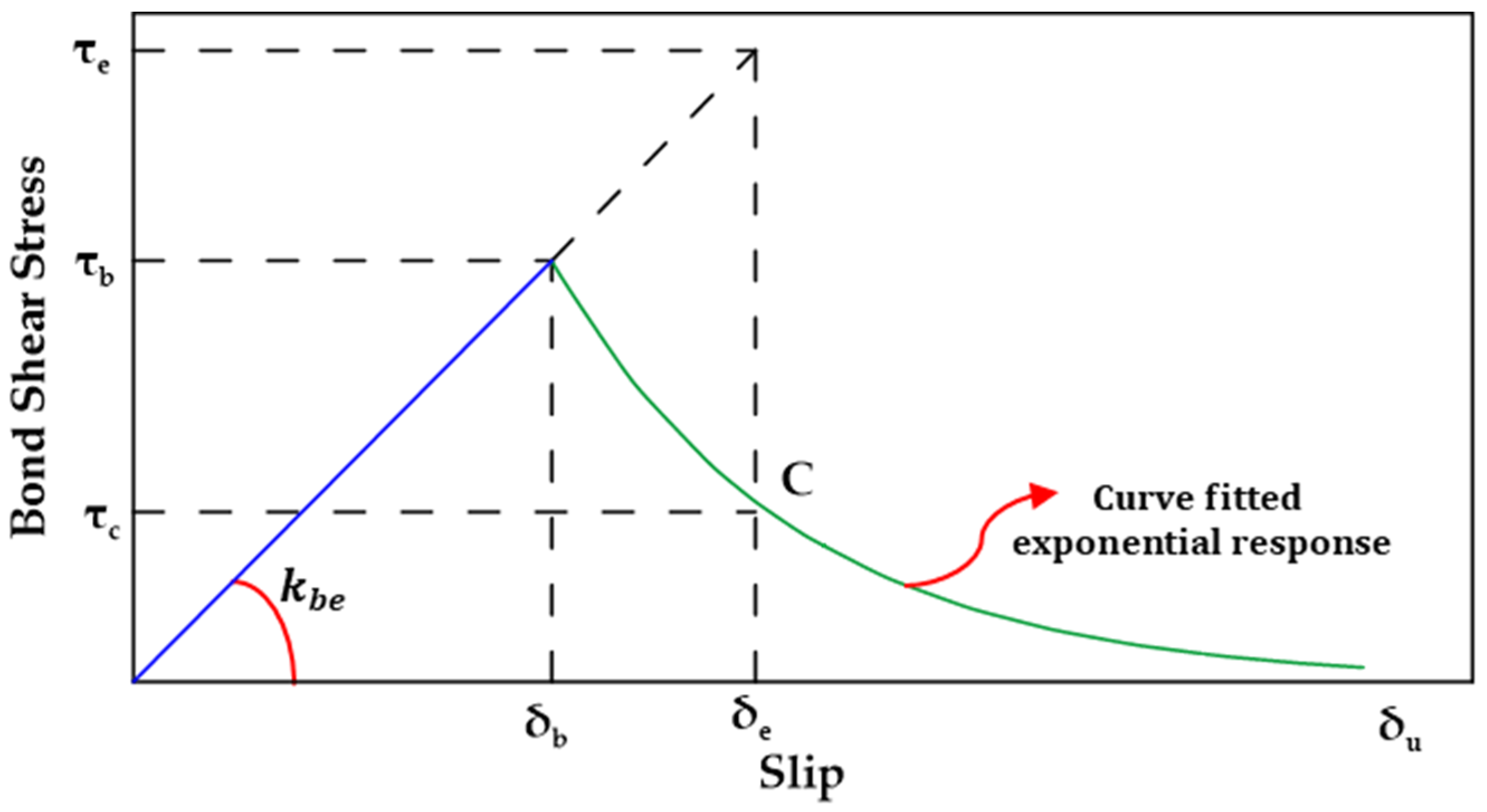
In the exponential damage approach, the bond shear stress–slip relationship between GFRP bars and concrete in the post-peak phase is described by an exponential function. This function quantifies the damage
in terms of the slip
as shown in Equation (11a,b), where
is the slip corresponding to ultimate failure and
is a parameter determined from the fitting of the known bond shear stress–slip curves.
Figure 26 shows a schematic representation of the exponential damage approach.
Furthermore, Biscaia and Carmo [
128] proposed a single-function bond–slip model used to simulate the pullout and the detachment process of an embedded rebar from a parent material [
128]. The model can be calibrated based on the bar type and the type of parent material used (i.e., concrete or timber). The proposed novel bond–slip model can reflect all stages of the bond response in one single function, the three stages being an elastic stage, a softening stage, and a friction stage. The proposed function is shown in Equation (12a,b), where
is the peak bond stress,
is the residual stress,
is the slip corresponding to the midpoint of the transition between the maximum and the residual stresses, and
and
are calibrated parameters.
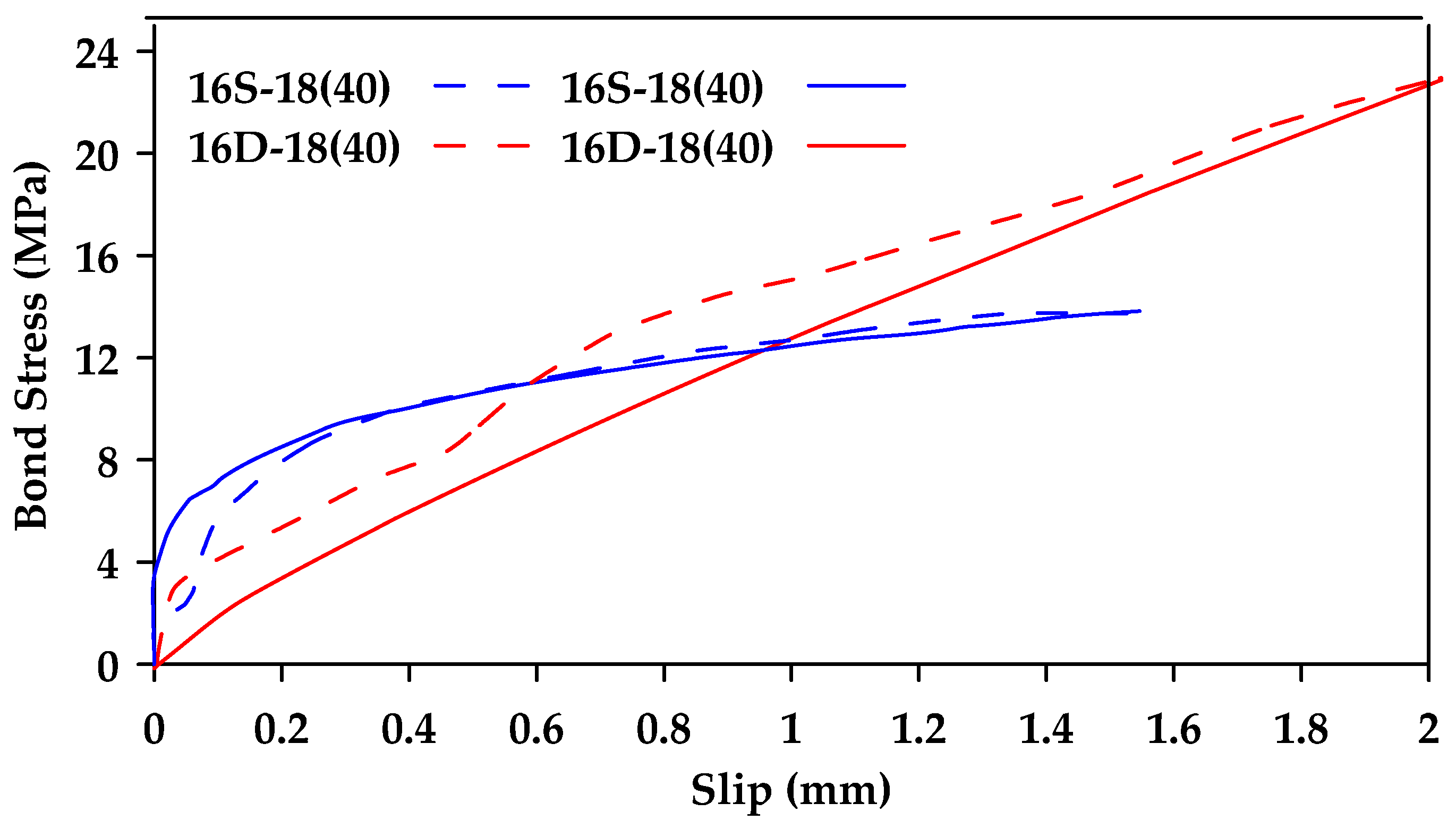
Figure 27 shows a comparison of the proposed model with experimental pullout tests on ribbed steel bars of varying diameter.
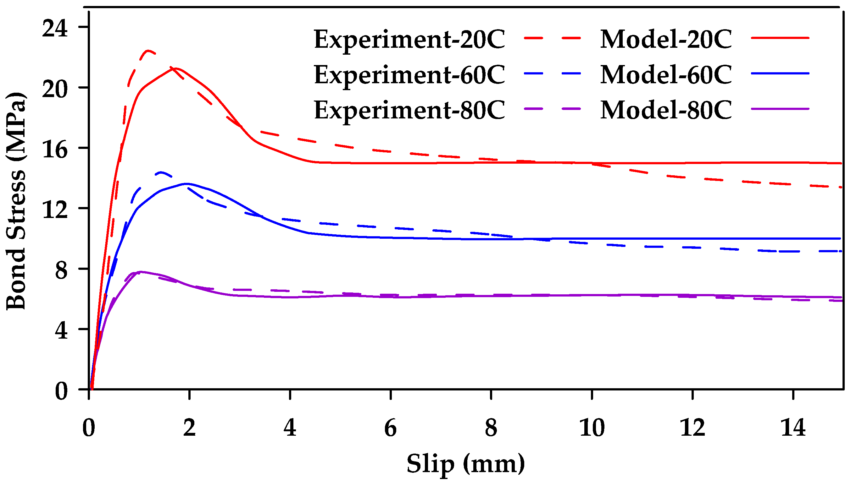
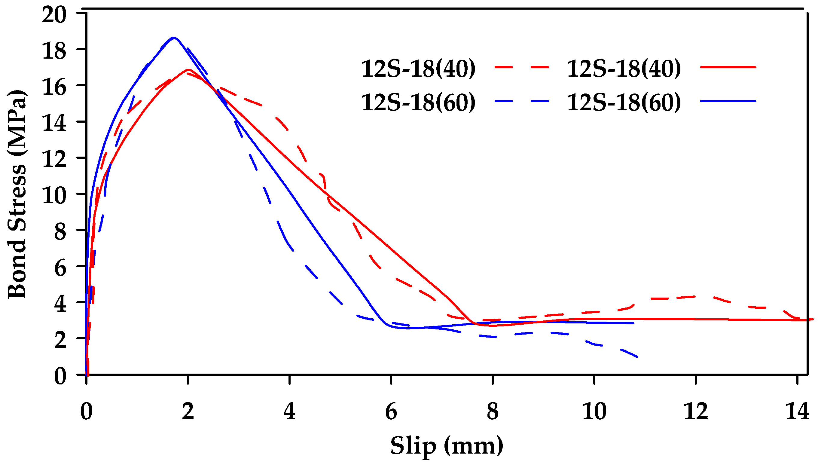
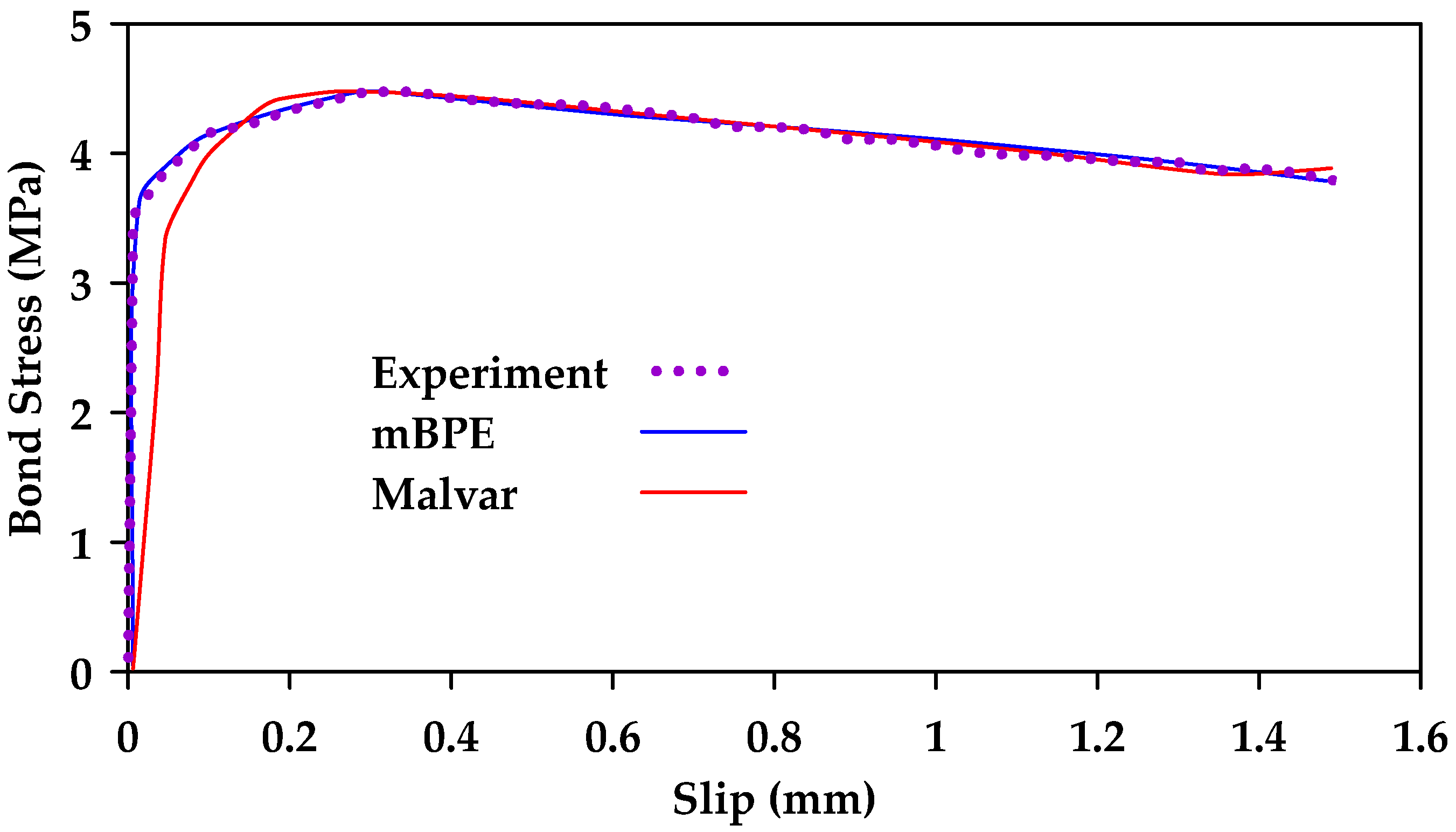
Figure 28 shows a comparison between experimental results from [
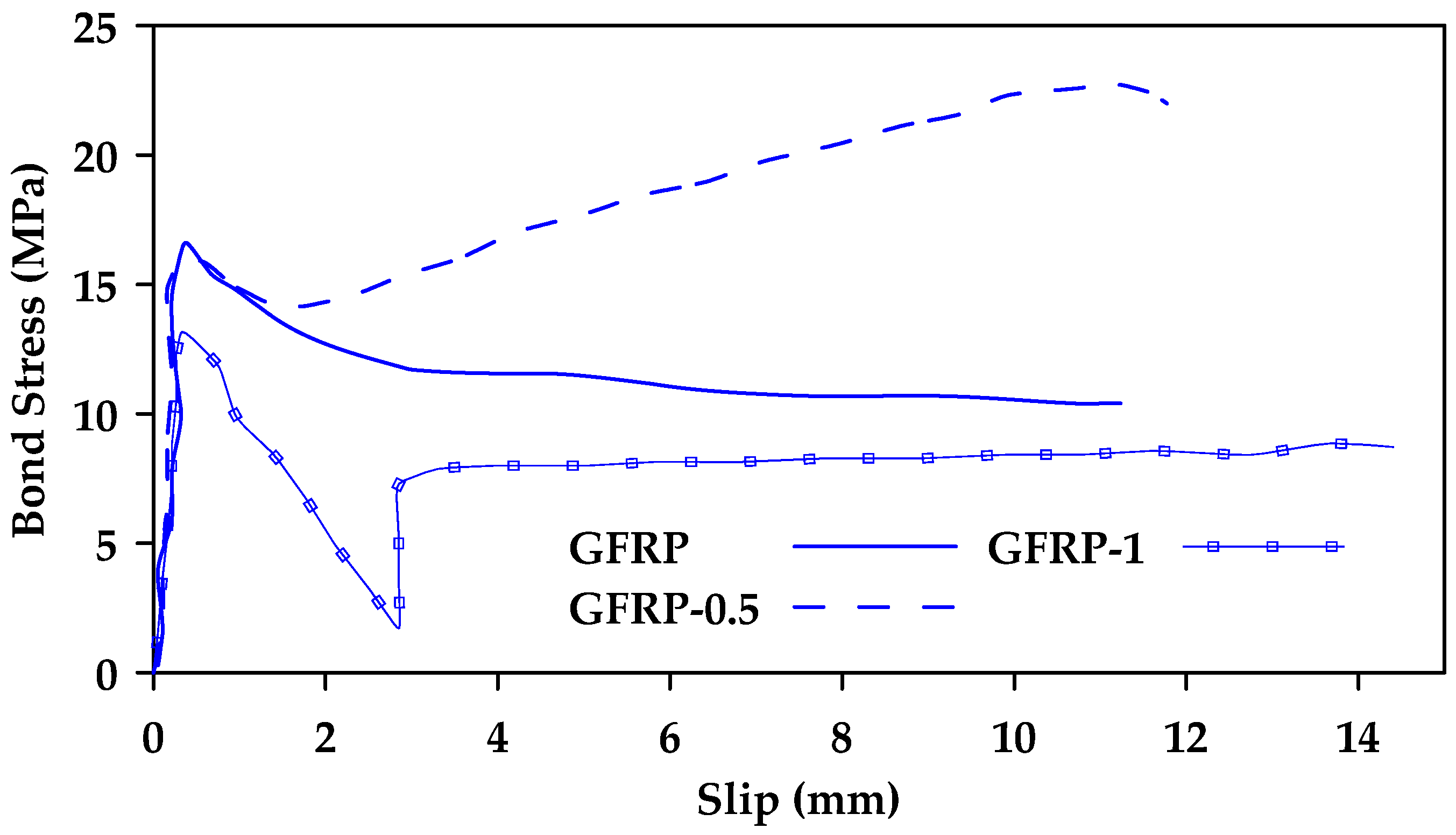
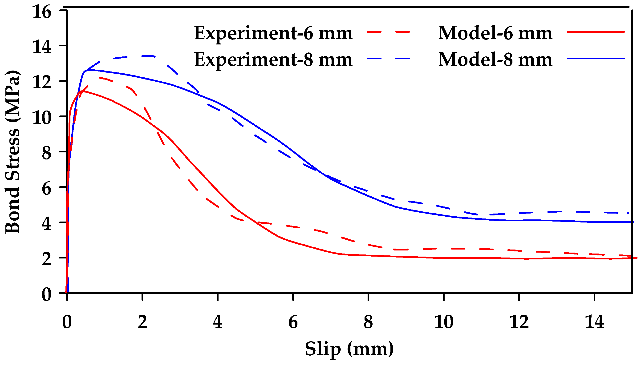
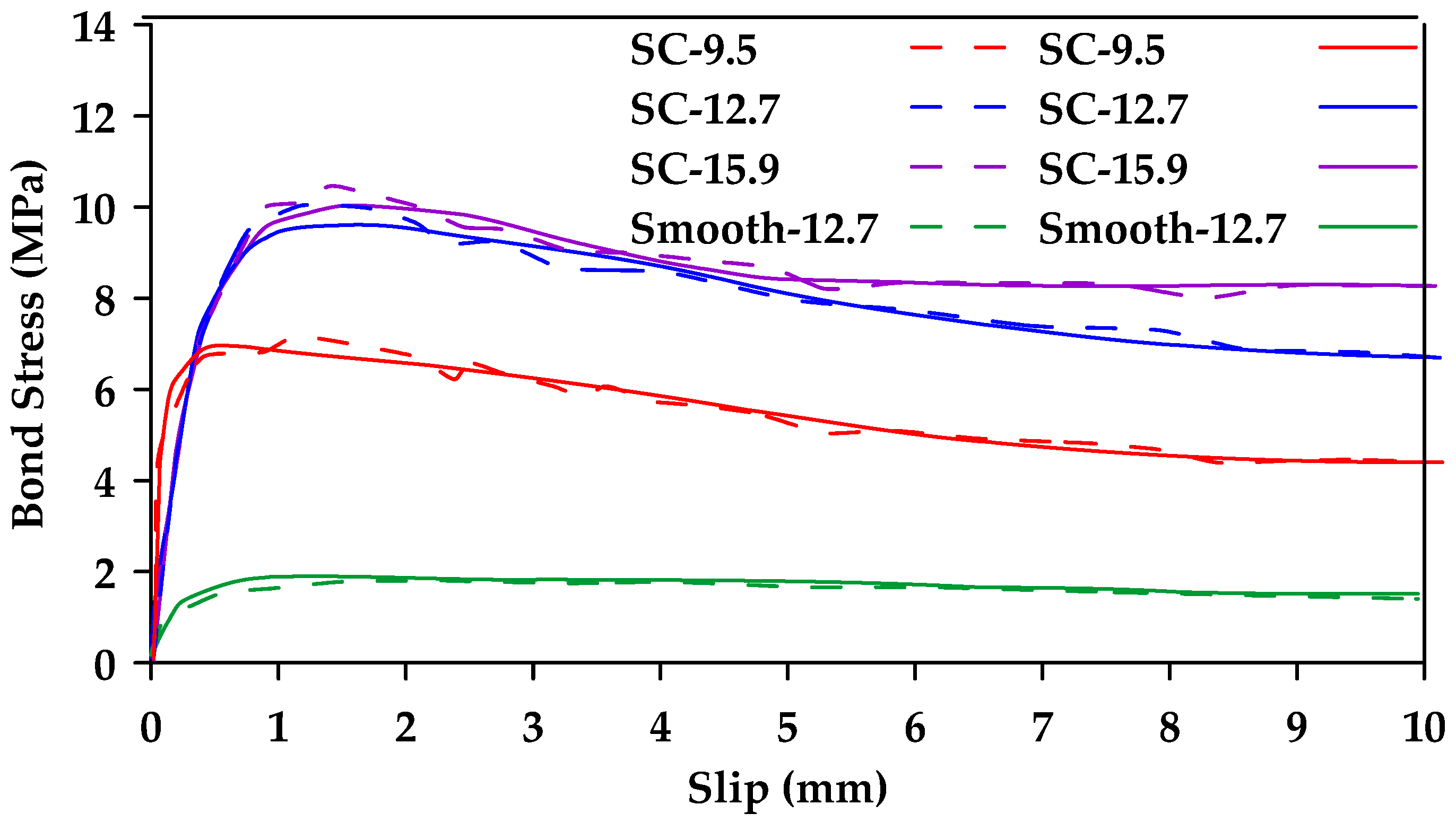
76] and model results for GFRP bars at different temperatures. Furthermore,
Figure 29 compares experimental results (dashed line) from [
129] and model results (Solid line) for sand-coated and smooth GFRP bars.


