

Tool Geometries and Design of Friction Stir Spot Welding (FSSW) Tools and Effect on Weld Properties—A Comprehensive Review


Abstract
1. Introduction
2. Scope of This Review Paper
3. Welding Strategies and Parameters
4. Effect of the Tool Shoulder
5. Effect of Tool Pin on Weld Joint Strength
6. Discussion and Recommendation
- (i)
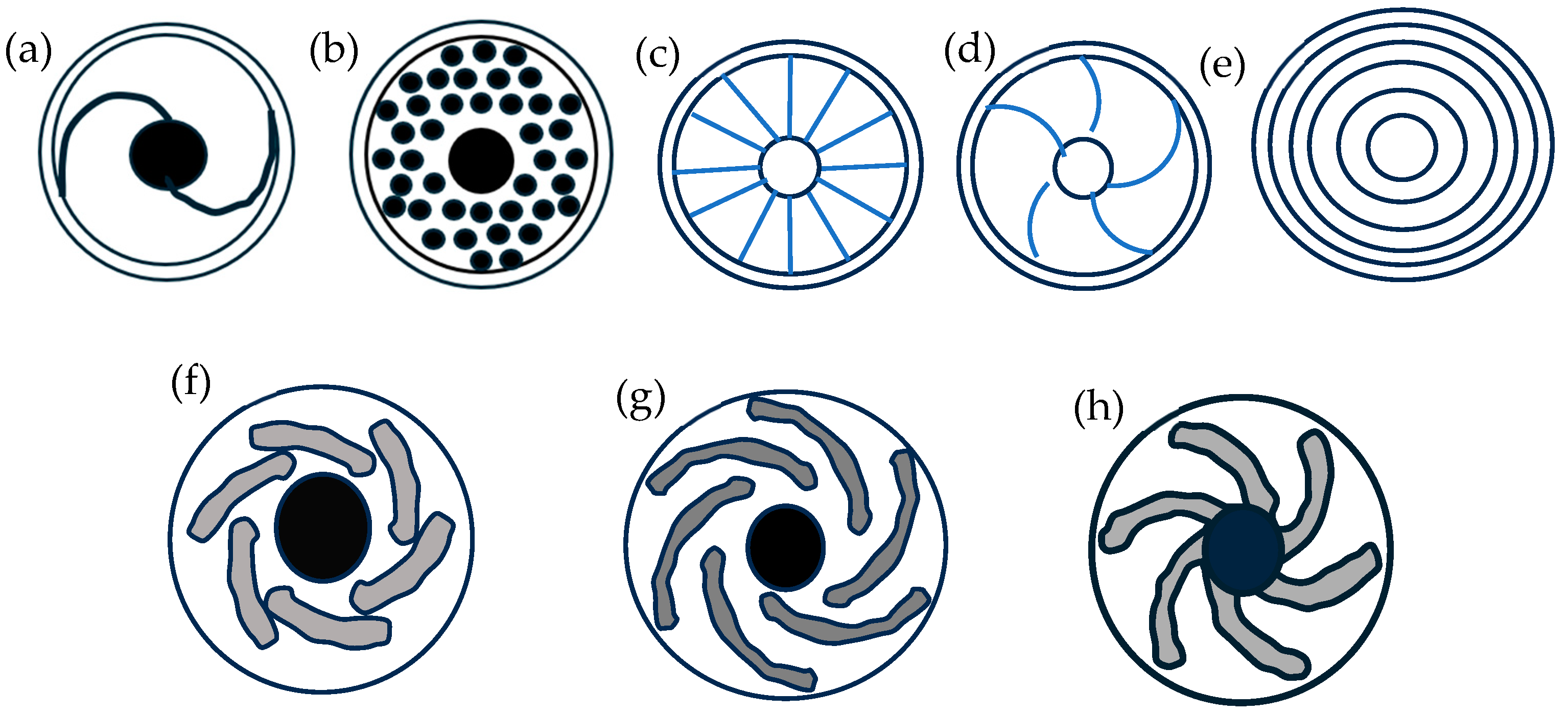
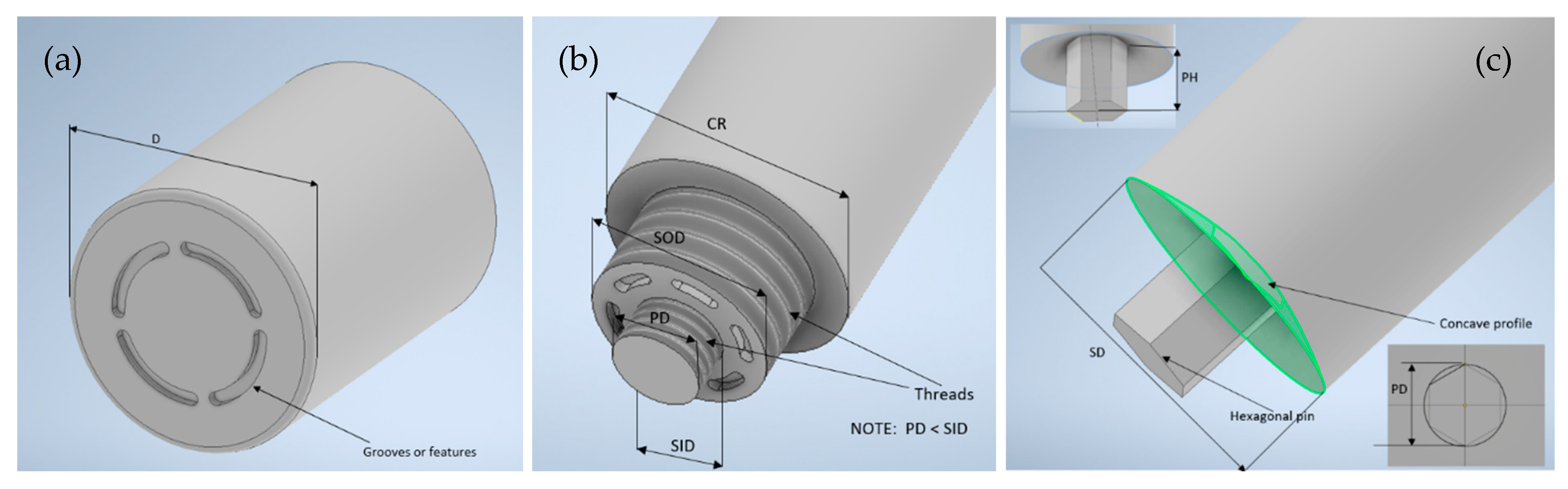
- P-FSSW: A concave-shaped tool (shoulder) with grooves or features such as involute or Fibonacci grooves and concentric features. P-FSSW creates fewer keyhole defects and produces spot welds with greater strengths compared to the use of a conventional FSSW tool [115]. P-FSSW tool is recommended for thin aluminum sheets (1 mm thick or less), as the conventional FSSW tool would create micro-defects on thin sheets [74]. The use of grooves in the P-FSSW tool assists with the penetration of the tool into the bottom sheet [116]. Referring to Table 2 and Figure 12a, the recommended and commonly used tool diameter is between 10 mm and 15 mm, and H13 or tungsten carbide is the tool material. D—pin-less tool shoulder diameter, M—tool material.
- (ii)
- R-FSSW: Grooves or threads on the inner sleeve or the surface of the pin. The sleeve and pin are responsible for the plasticization of the materials due to heating and shearing and the circulation of the materials for weld formation [27]. The inclusion of grooves or threads in these components of the R-FSSW tool further enhance material mixing and deliver stronger weld development. However, the groove/thread in between the clamping ring and sleeve is prone to wear due to the relative motion between these two parts [26,27,119]. Referring to Table 3 and Figure 12b, the recommended and commonly used tool diameter is a clamping ring diameter between 15 mm and 18 mm, a sleeve diameter between 7 mm and 9 mm, and a pin diameter between 5 mm and 6 mm. H13 is the suggested tool material. CR—clamping ring diameter, SOD—sleeve outer diameter, SID—sleeve inner diameter, PD—pin diameter, M—tool material.
- (iii)
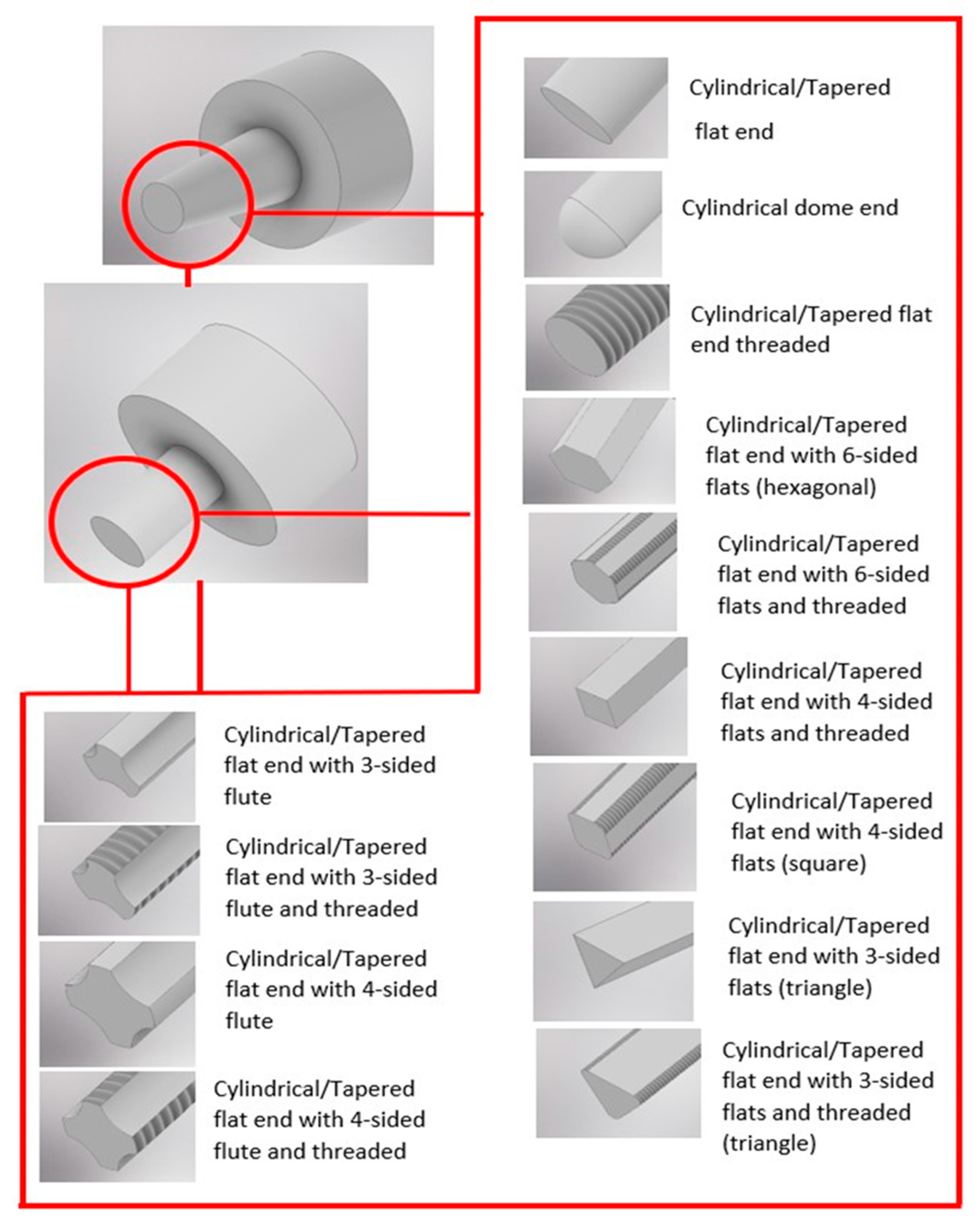
- FSSW: Tool shoulder preferably with a concave profile and pin shapes such as hexagonal, triangular, tapered, and cylindrical, with threads and flutes. The threaded pin with flutes promoted significantly more material mixing and heat generation than the threaded pin [123], and the concave profile tool with the threaded pin improved material mixing and minimized particle segregation [124]. The pin length of the tool depends on the shoulder diameter and features added to the pin [115]. Referring to Table 4 and Figure 12c, the recommended and commonly used shoulder diameter ranges from 10 mm to 20 mm, while the pin diameter ranges from 3 mm to 8 mm. Steel is the suggested tool material for joining aluminum, copper, or polymers, and tungsten carbide is recommended for joining steels. SD—shoulder diameter, PD—pin diameter, PH—pin height, M—tool material.
7. Conclusions
- The heat generated during welding is a combined contribution from the frictional heat from the tool shoulder and the heat developed due to the plastic deformation and stirring effect by the tool pin.
- Bigger shoulder diameters and pin diameters increase the heat generation during welding.
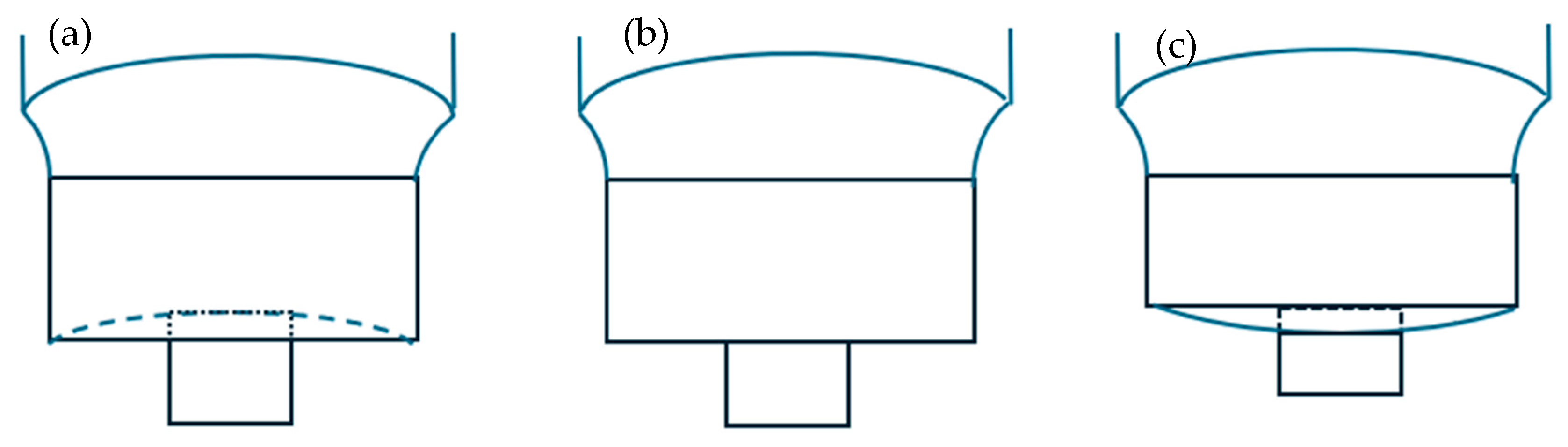
- A concave shoulder profile produces a stronger weld compared to flat and convex profiles due to its ability to trap materials and transfer materials to the sheet interface efficiently for the development of a sound weld.
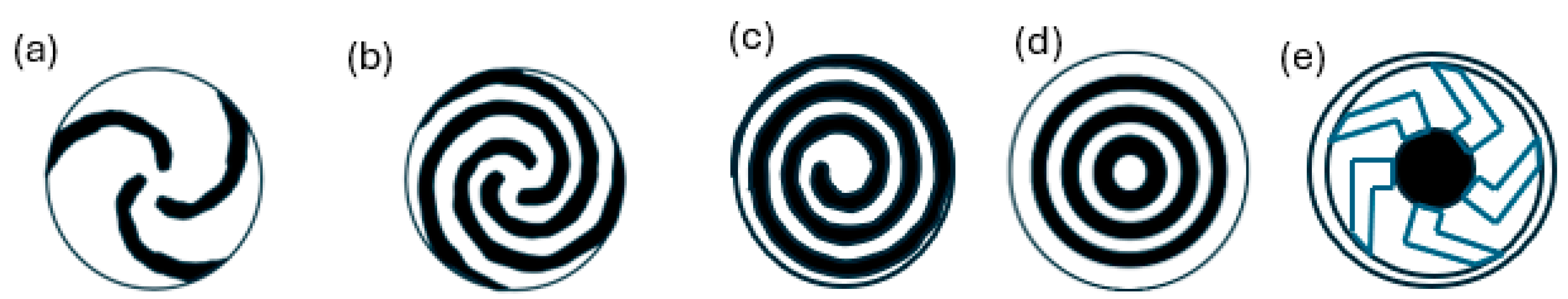
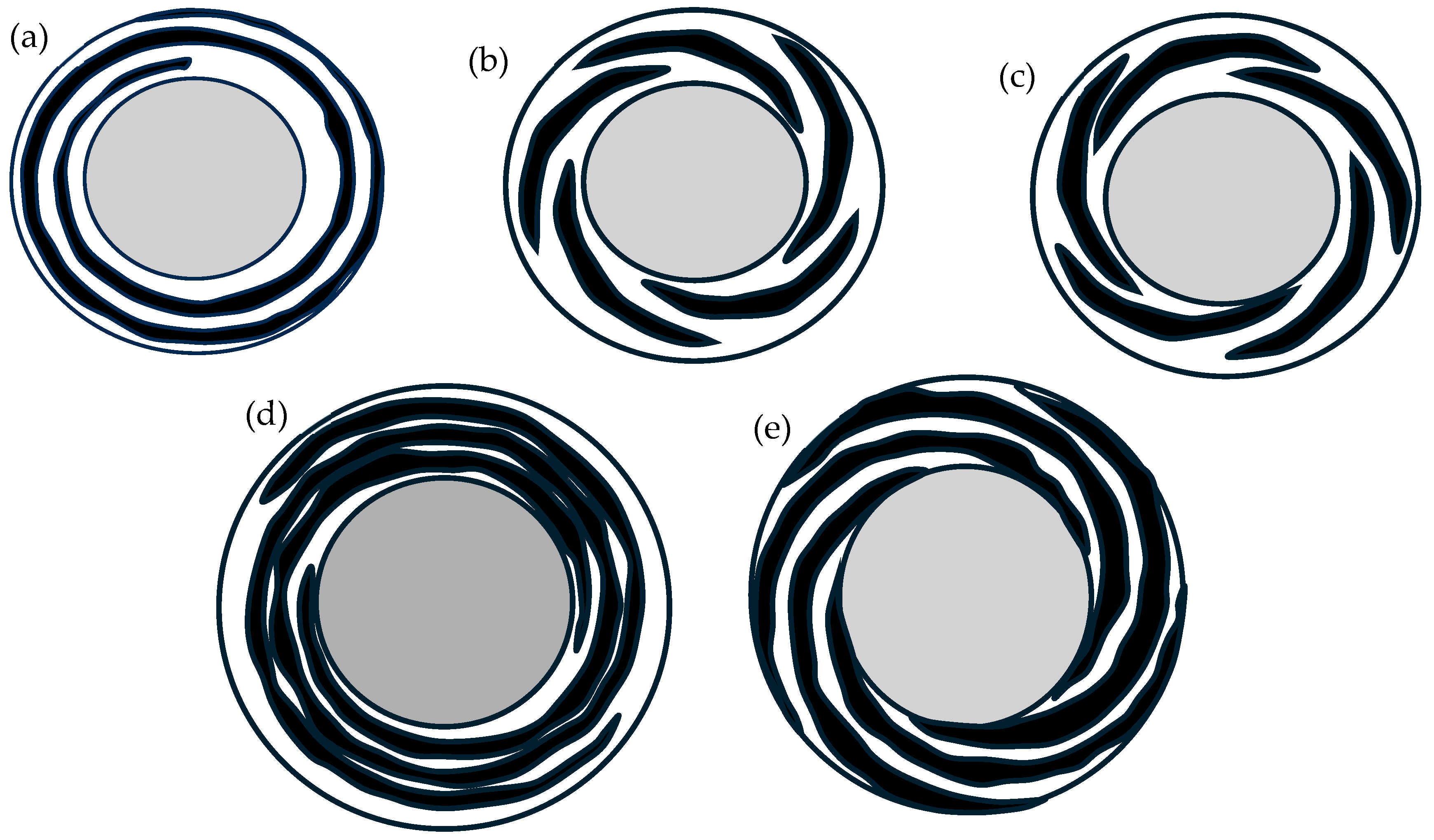
- Grooves such as Fibonacci and involute, and threads on P-FSSW and R-FSSW tools, also contribute to effective material flow during welding, hence assisting in heat generation and the development of a quality weld.
- The different shapes of pins, threads, and grooves on pins, and pin lengths, affect the materials’ plastic deformation and the flow of material upwards towards the tool shoulder.
- This review also provides recommendations on tool design for FSSW, P-FSSW, and R-FSSW.
Author Contributions
Funding
Institutional Review Board Statement
Informed Consent Statement
Data Availability Statement
Conflicts of Interest
References
- Czerwinski, F. Current Trends in Automotive Lightweighting Strategies and Materials. Materials 2021, 14, 6631. [Google Scholar] [CrossRef] [PubMed]
- Patel, V.K.; Patel, N.; Patel, M.D.; Shukla, H.A.; Patel, A.B.; Parmar, N.J. Innovations in Lightweight Materials for Automotive Engineering. J. Electr. Syst. 2024, 20, 2121–2133. [Google Scholar] [CrossRef]
- Li, Q.; Zhang, Y.; Zhang, C.; Wang, X.; Chen, J. Analysis Method and Case Study of the Lightweight Design of Automotive Parts and Its Influence on Carbon Emissions. Processes 2022, 10, 2560. [Google Scholar] [CrossRef]
- Li, J.; Wang, L.; Chen, Y.; Lu, H.; Jiang, H. Research and Application of Lightweight Index for Passenger Cars. Automot. Innov. 2020, 3, 270–279. [Google Scholar] [CrossRef]
- Taub, A.; De Moor, E.; Luo, A.; Matlock, D.K.; Speer, J.G.; Vaidya, U. Materials for Automotive Lightweighting. Annu. Rev. Mater. Res. 2019, 49, 327–359. [Google Scholar] [CrossRef]
- Blanco, D.; Rubio, E.M.; Lorente-Pedreille, R.M.; Sáenz-Nuño, M.A. Lightweight Structural Materials in Open Access: Latest Trends. Materials 2021, 14, 6577. [Google Scholar] [CrossRef] [PubMed]
- Wazeer, A.; Das, A.; Abeykoon, C.; Sinha, A.; Karmakar, A. Composites for electric vehicles and automotive sector: A review. Green Energy Intell. Transp. 2023, 2, 100043. [Google Scholar] [CrossRef]
- Paulraj, C.; Raj, V.J. An intelligent model for defect prediction in spot welding. Turk. J. Comput. Math. Educ. 2021, 12, 3991–4002. [Google Scholar]
- Xu, Y.; Chen, Q.; Wang, B.; Qiu, F.; Dong, B.; Li, H.; Feng, Z.; Barber, G.C. Dissimilar joining of aluminum alloy and low-alloy carbon steel by resistance spot welding. J. Mater. Res. Technol. 2024, 33, 919–928. [Google Scholar] [CrossRef]
- Pramanik, A.; Basak, A.; Dong, Y.; Sarker, P.; Uddin, M.; Littlefair, G.; Dixit, A.; Chattopadhyaya, S. Joining of carbon fibre reinforced polymer (CFRP) composites and aluminium alloys—A review. Compos. Part A Appl. Sci. Manuf. 2017, 101, 1–29. [Google Scholar] [CrossRef]
- Ren, S.; Ma, Y.; Saeki, S.; Iwamoto, Y.; Chen, C.; Ma, N. Fracture mechanism and strength evaluation of Al5052/CFRP joint produced by coaxial one-side resistance spot welding. Compos. Struct. 2020, 252, 112766. [Google Scholar] [CrossRef]
- Yang, X.W.; Fu, T.; Li, D.W. Friction Stir Spot Welding: A Review on Joint Macro- and Microstructure, Property, and Process Modelling. Adv. Mater. Sci. Eng. 2014, 2014, 697170. [Google Scholar] [CrossRef]
- Gonçalves, J.; dos Santos, J.; Canto, L.; Amancio-Filho, S. Friction spot welding of carbon fiber-reinforced polyamide 66 laminate. Mater. Lett. 2015, 159, 506–509. [Google Scholar] [CrossRef]
- Ibrahim, H.K.; Khuder, A.W.H.; Muhammed, M.A.S. Effects of rotational speeds and tool pin geometry on microstructure and mechanical properties of refilled friction stir spot welds of similar AA2024-T3 aluminum alloy sheets. Int. J. Eng. Res. Technol. (IJERT) 2017, 6, 937–952. [Google Scholar]
- Basak, A.; Pramanik, A.; Prakash, C.; Shankar, S.; Gupta, L.R.; Smirnov, V.A.; Al-Kahtani, A.A. Microstructural and micro-mechanical behaviours of friction stir processed magnesium alloy. J. Mater. Res. Technol. 2023, 25, 6303–6312. [Google Scholar] [CrossRef]
- Basak, A.; Pramanik, A.; Prakash, C.; Shankar, S.; Sehgal, S.S. Microstructure and micro-mechanical properties of friction stir processed Al 5086-based surface composite. Mater. Today Commun. 2023, 35, 105830. [Google Scholar] [CrossRef]
- Radhika, N.; Krishna, S.A.; Basak, A.K.; Adediran, A.A. Microstructure and tribological behaviour of CoCrCuFeTi high entropy alloy reinforced SS304 through friction stir processing. Sci. Rep. 2024, 14, 3662. [Google Scholar] [CrossRef]
- Yue, Y.; Shi, Y.; Ji, S.; Wang, Y.; Li, Z. Effect of Sleeve Plunge Depth on Microstructure and Mechanical Properties of Refill Friction Stir Spot Welding of 2198 Aluminum Alloy. J. Mater. Eng. Perform. 2017, 26, 5064–5071. [Google Scholar] [CrossRef]
- Abed, B.H.; Salih, O.S.; Sowoud, K.M. Pinless friction stir spot welding of aluminium alloy with copper interlayer. Open Eng. 2020, 10, 804–813. [Google Scholar] [CrossRef]
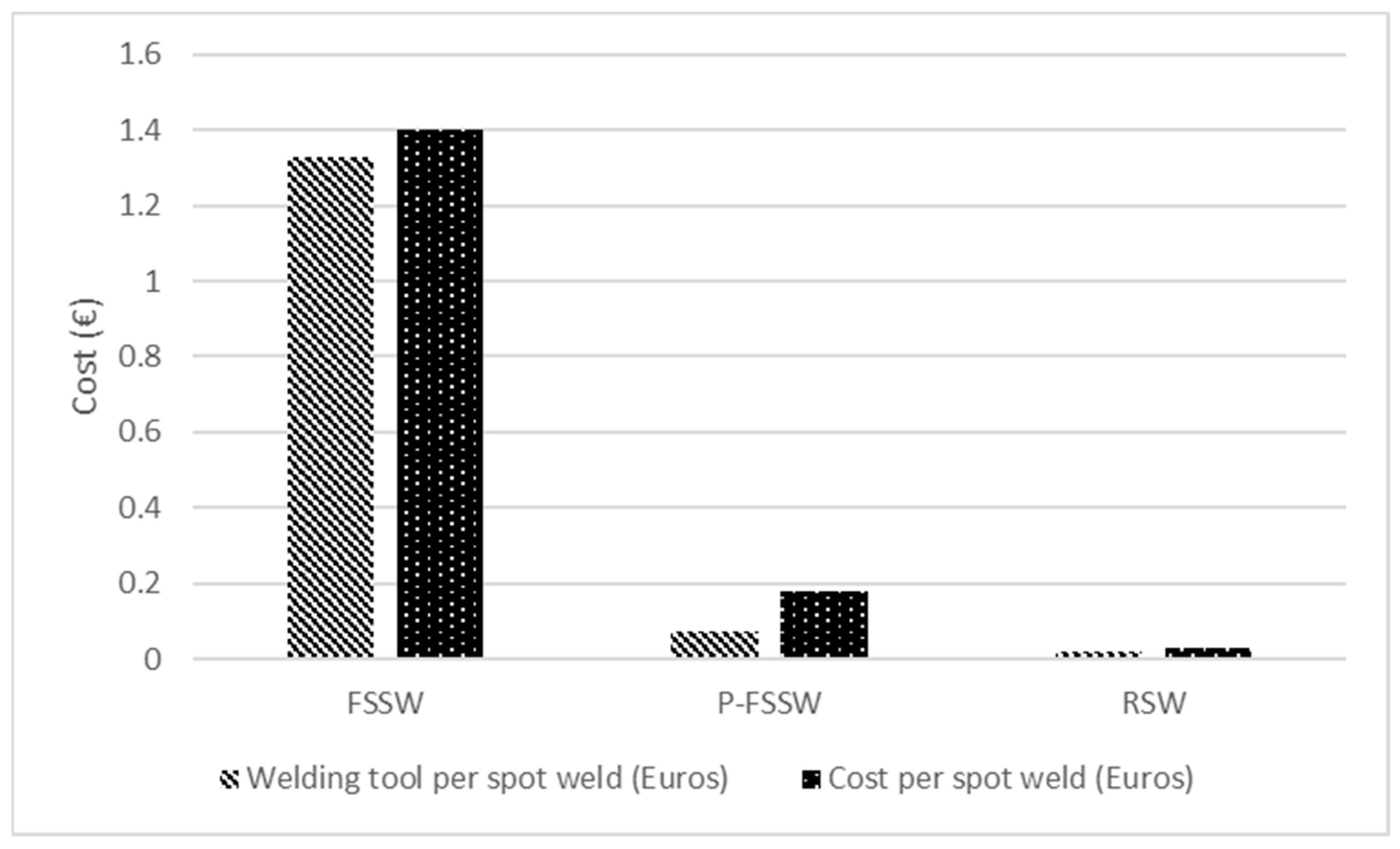
- Lunetto, V.; De Maddis, M.; Spena, P.R. Pre-hole friction stir spot welding of dual-phase steels and comparison with resistance spot welding, conventional and pinless friction stir spot welding. Int. J. Adv. Manuf. Technol. 2023, 129, 2333–2349. [Google Scholar] [CrossRef]
- Gale, D.; Smith, T.; Hovanski, Y.; Namola, K.; Coyne, J. A Comparison of the Microstructure and Mechanical Properties of RSW and RFSSW Joints in AA6061-T4 for Automotive Applications. J. Manuf. Mater. Process. 2024, 8, 260. [Google Scholar] [CrossRef]
- Basak, A.K.; Pramanik, A. Stainless Steel: Microstructure, Mechanical Properties and Methods of Application; Nova Science Publishers, Incorporated: Hauppauge, NY, USA, 2015. [Google Scholar]
- Basak, A.; Celis, J.-P.; Vardavoulias, M.; Matteazzi, P. Effect of nanostructuring and Al alloying on friction and wear behaviour of thermal sprayed WC–Co coatings. Surf. Coat. Technol. 2012, 206, 3508–3516. [Google Scholar] [CrossRef]
- Basak, A.K.; Matteazzi, P.; Vardavoulias, M.; Celis, J.P. Corrosion–wear behaviour of thermal sprayed nanostructured FeCu/WC–Co coatings. Wear 2006, 261, 1042–1050. [Google Scholar] [CrossRef]
- Belnap, R.; Smith, T.; Blackhurst, P.; Cobb, J.; Misak, H.; Bosker, J.; Hovanski, Y. Evaluating the Influence of Tool Material on the Performance of Refill Friction Stir Spot Welds in AA2029. J. Manuf. Mater. Process. 2024, 8, 88. [Google Scholar] [CrossRef]
- Fritsche, S.; Schindler, F.; de Carvalho, W.; Amancio-Filho, S. Wear mechanisms and failure analysis of a tool used in refill friction stir spot welding of AA6061-T6. Wear 2025, 560-561, 205610. [Google Scholar] [CrossRef]
- de Castro, C.C.; Shen, J.; Plaine, A.H.; Suhuddin, U.F.H.; de Alcantara, N.G.; dos Santos, J.F.; Klusemann, B. Tool wear mechanisms and effects on refill friction stir spot welding of AA2198-T8 sheets. J. Mater. Res. Technol. 2022, 20, 857–866. [Google Scholar] [CrossRef]
- Akbari, M.; Aliha, M.; Berto, F. Investigating the role of different components of friction stir welding tools on the generated heat and strain. Forces Mech. 2023, 10, 100166. [Google Scholar] [CrossRef]
- Budin, S.; Maideen, N.C.; Sahudin, S. Design and Development of Stirring Tool Pin Profile for Reconfigured Milling Machine to Perform Friction Stir Welding Process. IOP Conference Series. Mater. Sci. Eng. 2019, 505, 012089. [Google Scholar]
- Anand, R.; Sridhar, V. Studies on process parameters and tool geometry selecting aspects of friction stir welding—A review. Mater. Today Proc. 2019, 27, 576–583. [Google Scholar] [CrossRef]
- Mugada, K.K.; Adepu, K. Material flow and mechanical properties of friction stir welded Al-Mg-Si alloy: Role of concentric circles shoulder with non-circular pins. Proc. Inst. Mech. Eng. Part C J. Mech. Eng. Sci. 2021, 235, 5487–5499. [Google Scholar] [CrossRef]
- Jambhale, S.; Kumar, S.; Kumar, S. Effect of Process Parameters & Tool Geometries on Properties of Friction Stir Spot Welds: A Review. Univers. J. Eng. Sci. 2015, 3, 6–11. [Google Scholar]
- Jo, D.S.; Kahhal, P.; Kim, J.H. Optimization of Friction Stir Spot Welding Process Using Bonding Criterion and Artificial Neural Network. Materials 2023, 16, 3757. [Google Scholar] [CrossRef]
- Shete, M.; Yarasu, R.; Sonar, T.; Shelare, S. Improving friction stir spot welding of high-density polyethylene sheets for welding parameters and its optimization. Int. J. Interact. Des. Manuf. (IJIDeM) 2024, 18, 4513–4525. [Google Scholar] [CrossRef]
- Bîrsan, D.C.; Susac, F.; Teodor, V.G. Optimization and Analysis of Refill Friction Stir Spot Welding (RFSSW) Parameters of Dissimilar Aluminum Alloy Joints by FE and ANN Methods. Materials 2024, 17, 4586. [Google Scholar] [CrossRef] [PubMed]
- Suresh, S.; Venkatesan, K.; Rajesh, S. Optimization of process parameters for friction stir spot welding of AA6061/Al2O3 by Taguchi method. AIP Conf. Proc. 2019, 2128, 030018. [Google Scholar]
- Abbass, M.K.; Hussein, S.K.; Khudhair, A.A. Optimization of Mechanical Properties of Friction Stir Spot Welded Joints for Dissimilar Aluminum Alloys (AA2024-T3 and AA 5754-H114). Arab. J. Sci. Eng. 2016, 41, 4563–4572. [Google Scholar] [CrossRef]
- Gowda, V.P.N.; BE, N.; Muthiya, S.J.; Arockia Dhanraj, J.; Rushman, J.F.; Verma, A. Enhancing Friction Stir Spot Welding of Al 5754 and Al 6111 Joints Using Taguchi’s Technique. J. Eng. 2024, 2024, 7213167. [Google Scholar] [CrossRef]
- Suryanarayanan, R.; Sridhar, V.G. Optimizing the process parameters in Friction stir Spot Welding Of Dissimilar Aluminum Alloys Using Genetic Algorithm. IOP Conf. Ser. Mater. Sci. Eng. 2021, 1123, 012027. [Google Scholar] [CrossRef]
- Nandhakumar, S.; Seenivasan, S.; Chandraprakash, R. Parametric optimizationof friction stir spot welded aluminium AA6063 alloy joints. Mater. Today Proc. 2021, 37, 2897–2902. [Google Scholar]
- Sundaram, M.; Visvalingam, B. Optimizing the Friction Stir Spot Welding Parameters to Attain Maximum Strength in Al/Mg Dissimilar Joints. J. Weld. Join. 2016, 34, 23–30. [Google Scholar] [CrossRef]
- Wang, Y.; Li, P.; Jiang, H.; Yang, K.; Chen, Z.; Chuai, H.; Wu, X.; Meng, Q.; Ma, L. Microstructure and Mechanical Properties of Refill Friction Stir Spot-Welded Joints of 2A12Al and 7B04Al: Effects of Tool Size and Welding Parameters. Materials 2024, 17, 716. [Google Scholar] [CrossRef] [PubMed]
- Rajendran, C.; Sonar, T.; Ivanov, M.; Kumar, P.S.; Amarnath, V.; Lokanadham, R. Optimization of friction stir spot welding parameters for joining dissimilar AZ31B magnesium alloy and AA6061 aluminium alloy using response surface methodology. Int. J. Interact. Des. Manuf. (IJIDeM) 2023, 19, 115–126. [Google Scholar] [CrossRef]
- Özgül, H.G.; Dedeoğlu, O. Investigations of the Mechanical and Microstructural Effects of Pinless Tool Geometry on Friction Stir Spot Welding Process. Trans. Indian Inst. Met. 2020, 73, 2281–2289. [Google Scholar] [CrossRef]
- Chaudhary, N.; Singh, S. Multi-objective optimization of friction stir spot welded Al 6061-T6 incorporated with silicon carbide using hybrid Grey Rational Analysis- Taguchi technique. Mater. Today Proc. 2022; in press. [Google Scholar]
- Membala, S.B.; Sutresman, O.S.; Arsyad, H.; Widyianto, A. Indentifying the effect of micro friction stir spot welding (µFSSW) parameters on weld geometry, mechanical properties, and metallography on dissimilar materials of AZ31B and AA1100. East. Eur. J. Enterp. Technol. 2022, 118, 13–21. [Google Scholar] [CrossRef]
- Su, Z.-M.; Qiu, Q.-H.; Lin, P.-C. Design of Friction Stir Spot Welding Tools by Using a Novel Thermal-Mechanical Approach. Materials 2016, 9, 677. [Google Scholar] [CrossRef]
- Vaneghi, A.H.; Bagheri, B.; Shamsipur, A.; Mirsalehi, S.E.; Abdollahzadeh, A. Investigations into the formation of intermetallic compounds during pinless friction stir spot welding of AA2024-Zn-pure copper dissimilar joints. Weld. World 2022, 66, 2351–2369. [Google Scholar] [CrossRef]
- Manickam, S.; Rajendran, C.; Balasubramanian, V. Investigation of FSSW parameters on shear fracture load of AA6061 and copper alloy joints. Heliyon 2020, 6, e04077. [Google Scholar] [CrossRef]
- Ahmed, M.M.Z.; El-Sayed Seleman, M.M.; Albaijan, I.; Abd El-Aty, A. Microstructure, Texture, and Mechanical Properties of Friction Stir Spot-Welded AA5052-H32: Influence of Tool Rotation Rate. Materials 2023, 16, 3423. [Google Scholar] [CrossRef]
- Balasubramaniam, G.L.; Boldsaikhan, E.; Fukada, S.; Fujimoto, M.; Kamimuki, K. Effects of Refill Friction Stir Spot Weld Spacing and Edge Margin on Mechanical Properties of Multi-Spot-Welded Panels. J. Manuf. Mater. Process. 2020, 4, 55. [Google Scholar] [CrossRef]
- de Castro, C.C.; Plaine, A.H.; Dias, G.P.; de Alcântara, N.G.; dos Santos, J.F. Investigation of geometrical features on mechanical properties of AA2198 refill friction stir spot welds. J. Manuf. Process. 2018, 36, 330–339. [Google Scholar] [CrossRef]
- Lambiase, F.; Paoletti, A.; Di Ilio, A. Effect of tool geometry on loads developing in friction stir spot welds of polycarbonate sheets. Int. J. Adv. Manuf. Technol. 2016, 87, 2293–2303. [Google Scholar] [CrossRef]
- Amat, M.A.; Andhika, I.D.G.R.; Pratama, F.I.; Kiswanto, G.; Baskoro, A.S.; Syarif, J. The effects of tool geometry on static strength and the failure mode in micro-friction stir spot welding. Int. J. Adv. Manuf. Technol. 2024, 135, 2697–2715. [Google Scholar] [CrossRef]
- Zou, Y.; Li, W.; Yang, X.; Su, Y.; Chu, Q.; Shen, Z. Microstructure and mechanical properties of refill friction stir spot welded joints: Effects of tool size and welding parameters. J. Mater. Res. Technol. 2022, 21, 5066–5080. [Google Scholar] [CrossRef]
- Kim, J.-R.; Ahn, E.-Y.; Das, H.; Jeong, Y.-H.; Hong, S.-T.; Miles, M.; Lee, K.-J. Effect of tool geometry and process parameters on mechanical properties of friction stir spot welded dissimilar aluminum alloys. Int. J. Precis. Eng. Manuf. 2017, 18, 445–452. [Google Scholar] [CrossRef]
- Zlatanovic, D.L.; Balos, S.; Bergmann, J.P.; Rasche, S.; Pecanac, M.; Goel, S. Influence of Tool Geometry and Process Parameters on the Properties of Friction Stir Spot Welded Multiple (AA 5754 H111) Aluminium Sheets. Materials 2021, 14, 1157. [Google Scholar] [CrossRef] [PubMed]
- Thakkar, N.; Badheka, V. Tool Designing for Friction Stir Welding Variants. In Advances in Manufacturing Engineering: Select Proceedings of ICFAMMT 2022; Springer: Berlin/Heidelberg, Germany, 2022; pp. 175–193. [Google Scholar]
- Nugroho, A.W.; Dika, O.H.D.; Budiyantoro, C.; Himarosa, R.A. Characterization of Polypropylene Sheet Friction Stir Spot Welded Joint. J. Phys. Conf. Ser. 2021, 1858, 012007. [Google Scholar] [CrossRef]
- Xu, R.Z.; Ni, D.R.; Yang, Q.; Liu, C.Z.; Ma, Z.Y. Pinless Friction Stir Spot Welding of Mg-3Al-1Zn Alloy with Zn Interlayer. J. Mater. Sci. Technol. 2016, 32, 76–88. [Google Scholar] [CrossRef]
- Badarinarayan, H.; Shi, Y.; Li, X.; Okamoto, K. Effect of tool geometry on hook formation and static strength of friction stir spot welded aluminum 5754-O sheets. Int. J. Mach. Tools Manuf. 2009, 49, 814–823. [Google Scholar] [CrossRef]
- Geng, P.; Ma, H.; Li, W.; Murakami, K.; Wang, Q.; Ma, N.; Aoki, Y.; Fujii, H.; Chen, C. Improving bonding strength of Al/CFRTP hybrid joint through modifying friction spot joining tools. Compos. Part B Eng. 2023, 254, 110588. [Google Scholar] [CrossRef]
- Bilici, M.K.; Yükler, A.I. Influence of tool geometry and process parameters on macrostructure and static strength in friction stir spot welded polyethylene sheets. Mater. Des. 2012, 33, 145–152. [Google Scholar] [CrossRef]
- Lacki, P.; Kucharczyk, Z.; Śliwa, R.; Gałaczyński, T. Effect of Tool Shape on Temperature Field in Friction Stir Spot Welding. Arch. Metall. Mater. 2013, 58, 595–599. [Google Scholar] [CrossRef]
- Hirasawa, S.; Badarinarayan, H.; Okamoto, K.; Tomimura, T.; Kawanami, T. Analysis of effect of tool geometry on plastic flow during friction stir spot welding using particle method. J. Mater. Process. Technol. 2010, 210, 1455–1463. [Google Scholar] [CrossRef]
- Tanaka, K.; Nagae, Y. Friction Stir Spot Welding of Aluminum Alloy to Carbon Fiber-Reinforced Thermosetting Resin Coated by Thermoplastic Resin Using Tools with Different Surface Shapes. J. Compos. Sci. 2025, 9, 17. [Google Scholar] [CrossRef]
- Garg, A.; Bhattacharya, A. Strength and failure analysis of similar and dissimilar friction stir spot welds: Influence of different tools and pin geometries. Mater. Des. 2017, 127, 272–286. [Google Scholar] [CrossRef]
- Chu, X.; Yin, M.; Gao, J.; Wang, X.; Wang, Y. Effects of Shoulder Geometry on Microstructures and Mechanical Properties of Probeless Friction Stir Spot Welded Aluminum 7075-T651 Sheets. Metals 2020, 10, 1605. [Google Scholar] [CrossRef]
- Yu, G.; Chen, X.; Wu, Z.; Zhang, G.; Chen, Y. Effect of tool groove features on the microstructure and tensile-shear mechanical performances of probeless friction stir spot welds. Int. J. Adv. Manuf. Technol. 2022, 121, 1837–1850. [Google Scholar]
- Chu, Q.; Hao, S.; Li, W.; Yang, X.; Zou, Y.; Wu, D. Impact of shoulder morphology on macrostructural forming and the texture development during probeless friction stir spot welding. J. Mater. Res. Technol. 2021, 12, 2042–2054. [Google Scholar] [CrossRef]
- Ge, X.; Kolupaev, I.N.; Jiang, D.; Wang, H. Investigation on the welded joint properties of pinless friction stir spot welding of copper under different tool grooves. Ferroelectrics 2024, 618, 2339–2354. [Google Scholar] [CrossRef]
- Yazdi, S.R.; Beidokhti, B.; Haddad-Sabzevar, M. Pinless tool for FSSW of AA 6061-T6 aluminum alloy. J. Mater. Process. Technol. 2019, 267, 44–51. [Google Scholar] [CrossRef]
- Atak, A. Impact of pinless stirring tools with different shoulder profile designs on friction stir spot welded joints. J. Mech. Sci. Technol. 2020, 34, 3735–3743. [Google Scholar] [CrossRef]
- Bakavos, D.; Chen, Y.; Babout, L.; Prangnell, P. Material Interactions in a Novel Pinless Tool Approach to Friction Stir Spot Welding Thin Aluminum Sheet. Metall. Mater. Trans. A 2011, 42, 1266–1282. [Google Scholar] [CrossRef]
- Li, W.; Geng, P.; Ma, N.; Fujii, H.; Ma, H. Effect of tool shoulder geometry on lapped Al/CFRTP hybrid joint structure and strength made by pinless friction spot joining. J. Mater. Res. Technol. 2024, 33, 2183–2198. [Google Scholar] [CrossRef]
- Draper, J.; Fritsche, S.; de Traglia Amancio-Filho, S.; Galloway, A.; Toumpis, A. Exploring a novel chamfered tool design for short duration refill friction stir spot welds of high strength aluminium. Int. J. Adv. Manuf. Technol. 2024, 131, 5867–5879. [Google Scholar] [CrossRef]
- Shen, Z.; Ding, Y.; Gopkalo, O.; Diak, B.; Gerlich, A. Effects of tool design on the microstructure and mechanical properties of refill friction stir spot welding of dissimilar Al alloys. J. Mater. Process. Technol. 2018, 252, 751–759. [Google Scholar] [CrossRef]
- Łogin, W.; Śliwa, R.; Ostrowski, R.; Andres, J. The Influence of Tool Geometry for Refill Friction Stir Spot Welding (RFSSW) on Weld Properties During Joining Thin Sheets of Aluminum Alloys. Arch. Metall. Mater. 2019, 64, 975–981. [Google Scholar] [CrossRef]
- Łogin, W.; Śliwa, R.; Ostrowski, R. The Influence of Modification of the Front Surface Geometry of the RFSSW Tool Sleeve on the Plasticization Effect and Stirring Materials During Joining Sheets Made of Aluminum Alloy 2024. Arch. Metall. Mater. 2022, 67, 1435–1442. [Google Scholar] [CrossRef]
- Li, Y.; Sun, G.; Zhang, Z.; Zhou, L.; Guo, N.; Dong, J.; Zhao, H. Effect of tool geometry on hook formation and mechanical properties of refill friction stir spot welding in alclad 2A12-T42 aluminium alloy. Sci. Technol. Weld. Join. 2023, 28, 478–487. [Google Scholar] [CrossRef]
- Ji, S.; Wang, Y.; Li, Z.; Yue, Y.; Chai, P. Effect of Tool Geometry on Material Flow Behavior of Refill Friction Stir Spot Welding. Trans. Indian Inst. Met. 2017, 70, 1417–1430. [Google Scholar] [CrossRef]
- Takeoka, N.; Miyama, T.; Matsuda, T.; Ogura, T.; Ohashi, R.; Hirose, A. Development of aluminum alloy/galvanized steel joining method using refill friction stir spot welding. Weld. Int. 2022, 36, 370–378. [Google Scholar] [CrossRef]
- Feizollahi, V.; Gerami, Y.; Saki, A.; Adelzadeh, B.; Zamani, M.; Hasab, M.G.; Moghadam, A.H. The effect of pin diameter, tool penetration depth and plate arrangement on mechanical and metallurgical properties of 6061-T6 and 5052-T32 aluminum dissimilar joints in friction stir spot welding (FSSW). Heliyon 2024, 10, e36962. [Google Scholar] [CrossRef]
- Yan, Y.; Shen, Y.; Lei, H.; Zhuang, J. Influence of welding parameters and tool geometry on the morphology and mechanical performance of ABS friction stir spot welds. Int. J. Adv. Manuf. Technol. 2019, 103, 2319–2330. [Google Scholar] [CrossRef]
- Zhang, Y.N.; Cao, X.; Larose, S.; Wanjara, P. Review of tools for friction stir welding and processing. Can. Metall. Q. 2012, 51, 250–261. [Google Scholar] [CrossRef]
- Alkhafaji, A.; Camas, D.; Lopez-Crespo, P.; Al-Asadi, H. The Influence of Tool Geometry on the Mechanical Properties and the Microstructure of AA6061-T6 Aluminum Alloy Friction Stir Spot Welding. Materials 2023, 16, 4135. [Google Scholar] [CrossRef]
- Badarinarayan, H.; Yang, Q.; Zhu, S. Effect of tool geometry on static strength of friction stir spot-welded aluminum alloy. Int. J. Mach. Tools Manuf. 2009, 49, 142–148. [Google Scholar] [CrossRef]
- Tiwan, H.; Ilman, M.N.; Kusmono, K. Effect of Pin Geometry and Tool Rotational Speed on Microstructure and Mechanical Properties of Friction Stir Spot Welded Joints in AA2024-O Aluminum Alloy. Int. J. Eng. 2021, 34, 1949–1960. [Google Scholar]
- Tiwan; Ilman, M.N.; Kusmono; Sehono. Microstructure and mechanical performance of dissimilar friction stir spot welded AA2024-O/AA6061-T6 sheets: Effects of tool rotation speed and pin geometry. Int. J. Lightweight Mater. Manuf. 2023, 6, 1–14. [Google Scholar] [CrossRef]
- Vidakis, N.; Mountakis, N.; Moutsopoulou, A.; David, C.; Nasikas, N.K.; Petousis, M. The impact of process parameters pin-to-shoulder diameter ratio on the welding performance of polycarbonate in FSW. Int. J. Adv. Manuf. Technol. 2023, 128, 4593–4613. [Google Scholar] [CrossRef]
- Borah, M.J.; Rajbongshi, S.K.; Saha, N.; Buddhi, D. Friction stir spot welding process: An innovative approach for transforming from engineering design to production. Int. J. Interact. Des. Manuf. 2023, 17, 2259–2270. [Google Scholar] [CrossRef]
- Garg, A.; Bhattacharya, A. Characterizing various zones formed in friction stir spot welding with different tool pins. In the Proceedings of the 16th International Aluminum Alloys Conference (ICAA16), Montreal, MO, Canada, 17–21 June 2018. [Google Scholar]
- Aydın, H.; Tunçel, O.; Tutar, M.; Bayram, A. Effect of tool pin profile on the hook geometry and mechanical properties of a friction stir spot welded AA6082-T6 aluminum alloy. Trans. Can. Soc. Mech. Eng. 2021, 45, 233–248. [Google Scholar] [CrossRef]
- Shin, H.-S. Tool geometry effect on the characteristics of dissimilar friction stir spot welded bulk metallic glass to lightweight alloys. J. Alloys Compd. 2014, 586, S50–S55. [Google Scholar] [CrossRef]
- Nugroho, A.W.; Fathurahman, A.; Rahman, M.B.N. The effect of welding parameter and tool geometry on polypropylene sheet friction stir spot welded joint. AIP Conf. Proc. 2023, 2865, 040010. [Google Scholar]
- Abbass, M.K.; Hussein, S.K.; Kudair, A.A. Optimization and Characterization of Friction Stir Spot Welding of Aluminum Alloy (AA 5754-H114) with Pure Copper Sheet. IOP Conf. Ser. Mater. Sci. Eng. 2021, 1094, 012054. [Google Scholar] [CrossRef]
- Choi, D.-H.; Ahn, B.-W.; Lee, C.-Y.; Yeon, Y.-M.; Song, K.; Jung, S.-B. Effect of Pin Shapes on Joint Characteristics of Friction Stir Spot Welded AA5J32 Sheet. Mater. Trans. 2010, 51, 1028–1032. [Google Scholar] [CrossRef]
- Yuan, W.; Mishra, R.; Webb, S.; Chen, Y.; Carlson, B.; Herling, D.; Grant, G. Effect of tool design and process parameters on properties of Al alloy 6016 friction stir spot welds. J. Mater. Process. Technol. 2011, 211, 972–977. [Google Scholar] [CrossRef]
- Lin, Y.-C.; Liu, J.-J.; Chen, J.-N. Material Flow Tracking for Various Tool Geometries During the Friction Stir Spot Welding Process. J. Mater. Eng. Perform. 2013, 22, 3674–3683. [Google Scholar] [CrossRef]
- Paidar, M.; Khodabandeh, A.; Sarab, M.L.; Taheri, M. Effect of welding parameters (plunge depths of shoulder, pin geometry, and tool rotational speed) on the failure mode and stir zone characteristics of friction stir spot welded aluminum 2024-T3 sheets. J. Mech. Sci. Technol. 2015, 29, 4639–4644. [Google Scholar] [CrossRef]
- Li, Z.; Yue, Y.; Ji, S.; Peng, C.; Wang, L. Optimal design of thread geometry and its performance in friction stir spot welding. Mater. Des. 2016, 94, 368–376. [Google Scholar] [CrossRef]
- Lin, Y.-C.; Chen, J.-N. Influence of process parameters on friction stir spot welded aluminum joints by various threaded tools. J. Mater. Process. Technol. 2015, 225, 347–356. [Google Scholar] [CrossRef]
- Yin, Y.H.; Sun, N.; North, T.H.; Hu, S.S. Influence of tool design on mechanical properties of AZ31 friction stir spot welds. Sci. Technol. Weld. Join. 2010, 15, 81–86. [Google Scholar] [CrossRef]
- Feizollahi, V.; Moghadam, A.H. Effect of pin geometry, rotational speed, and dwell time of tool in dissimilar joints of low-carbon galvanized steel and aluminum 6061-T6 by friction stir spot welding. Results Mater. 2023, 20, 100483. [Google Scholar] [CrossRef]
- Piccini, J.M.; Svoboda, H.G. Tool geometry optimization in friction stir spot welding of Al-steel joints. J. Manuf. Process. 2017, 26, 142–154. [Google Scholar] [CrossRef]
- Safitri, L.A.; Fakhrurrozi, I.F.; Amat, M.A.; Baskoro, A.S.; Rupajati, P.; Kiswanto, G. Effect of Tool Profile on Mechanical Properties, Temperature, and RPM Using Micro Friction Stir Spot Welding (mFSSW) on Aluminum Alloy AA1100. J. Phys. Conf. Ser. 2024, 2739, 012024. [Google Scholar] [CrossRef]
- Baskoro, A.S.; Prayogo, G.; Amat, M.A.; Eshandra, R.A.; Pahlevi, M.S. The fatigue strength of micro friction stir spot welding of AA1100 thin plate using different tools geometry. AIP Conf. Proc. 2023, 2837, 040014. [Google Scholar]
- Tozaki, Y.; Uematsu, Y.; Tokaji, K. Effect of tool geometry on microstructure and static strength in friction stir spot welded aluminium alloys. Int. J. Mach. Tools Manuf. 2007, 47, 2230–2236. [Google Scholar] [CrossRef]
- Mohan, A.E.; Sajuri, Z.; Baghdadi, A.H.; Jamadon, N.H.; Abbasi, M. Influences of Graphene Nanoplatelet Addition and Pin Lengths on the Microstructure and Mechanical Properties of 7075 Aluminum Alloy Under Friction Stir Spot Welding. J. Mater. Res. Technol. 2024, 31, 3436–3452. [Google Scholar] [CrossRef]
- Yang, Q.; Mironov, S.; Sato, Y.; Okamoto, K. Material flow during friction stir spot welding. Mater. Sci. Eng. A 2010, 527, 4389–4398. [Google Scholar] [CrossRef]
- Sarkar, R.; Pal, T.; Shome, M. Material Flow and Intermixing during Friction Stir Spot Welding of Steel. J. Mater. Process. Technol. 2015, 227, 96–109. [Google Scholar] [CrossRef]
- Akbari, M.; Asadi, P. Effects of triflute pin geometry on defect formation and material flow in FSW using CEL approach. J. Adv. Join. Process. 2024, 10, 100259. [Google Scholar] [CrossRef]
- Rashkovets, M.; Dell’aVvocato, G.; Contuzzi, N.; Palumbo, D.; Galietti, U.; Casalino, G. On the role of rotational speed in P-FSSW dissimilar aluminum alloys lap weld. Weld. World 2025, 69, 2095–2107. [Google Scholar] [CrossRef]
- Elyasi, M.; Taherian, J.; Hosseinzadeh, M.; Kubit, A.; Derazkola, H.A. The effect of pin thread on material flow and mechanical properties in friction stir welding of AA6068 and pure copper. Heliyon 2023, 9, e14752. [Google Scholar] [CrossRef]
- Cox, C.D.; Gibson, B.T.; Strauss, A.M.; Cook, G.E. Effect of Pin Length and Rotation Rate on the Tensile Strength of a Friction Stir Spot-Welded Al Alloy: A Contribution to Automated Production. Mater. Manuf. Process. 2012, 27, 472–478. [Google Scholar] [CrossRef]
- Çakan, B.G.; Tunçel, O.; Tutar, M. Friction Stir Spot Weldability of AA7075-T6 Sheets with a Pinless Tool Providing Enhanced Stirring Effect. JOM 2025, 77, 389–399. [Google Scholar] [CrossRef]
- Reilly, A.; Shercliff, H.; Chen, Y.; Prangnell, P. Modelling and Visualisation of Material Flow in Friction Stir Spot Welding. J. Mater. Process. Technol. 2015, 225, 473–484. [Google Scholar] [CrossRef]
- Pereira, M.A.R.; Galvão, I.; Costa, J.D.M.; Amaro, A.M.; Leal, R.M. Metal-polymer friction stir spot welding enhanced by meso-mechanical interlocking. Int. J. Adv. Manuf. Technol. 2025, 136, 4581–4593. [Google Scholar] [CrossRef]
- Lauterbach, D.; Keil, D.; Harms, A.; Leupold, C.; Dilger, K. Tool wear behaviour and the influence of wear-resistant coatings during refill friction stir spot welding of aluminium alloys. Weld. World 2021, 65, 243–250. [Google Scholar] [CrossRef]
- Shen, Z.; Ding, Y.; Chen, J.; Fu, L.; Liu, X.C.; Chen, H.; Guo, W.; Gerlich, A.P. Microstructure, static and fatigue properties of refill friction stir spot welded 7075-T6 aluminum alloy using a modified tool. Sci. Technol. Weld. Join. 2018, 24, 587–600. [Google Scholar] [CrossRef]
- Kubit, A.; Trzepiecinski, T. A fully coupled thermo-mechanical numerical modelling of the refill friction stir spot welding process in Alclad 7075-T6 aluminium alloy sheets. Arch. Civ. Mech. Eng. 2020, 20, 117. [Google Scholar] [CrossRef]
- Berger, E.; Miles, M.; Curtis, A.; Blackhurst, P.; Hovanski, Y. 2D Axisymmetric Modeling of Refill Friction Stir Spot Welding and Experimental Validation. J. Manuf. Mater. Process. 2022, 6, 89. [Google Scholar] [CrossRef]
- Subramanian, S.; Natarajan, E.; Khalfallah, A.; Muthukutti, G.P.; Beygi, R.; Louhichi, B.; Sengottuvel, R.; Ang, C.K. Current Trends and Emerging Strategies in Friction Stir Spot Welding for Lightweight Structures: Innovations in Tool Design, Robotics, and Composite Reinforcement—A Review. Crystals 2025, 15, 556. [Google Scholar] [CrossRef]
- Sabry, I. Enhanced strength, ductility, and corrosion resistance of AA6061/AA6082 alloys using Al-SiC matrix reinforcement in dissimilar friction stir welding. Int. J. Adv. Manuf. Technol. 2025, 138, 2431–2457. [Google Scholar] [CrossRef]
- Akinlabi, E.T.; Sanusi, K.O.; Muzenda, E.; Akinlabi, S.A. Material behaviour characterization of Friction Stir Spot Welding of Copper. Mater. Today Proc. 2017, 4 Pt A, 166–177. [Google Scholar] [CrossRef]
- Devarajan, K.; Karuppanan, V.V.S.; Duraisamy, T.; Bhavirisetty, S.K.; Laxmaiah, G.; Chauhan, P.K.; Razak, A.; Asif, M.; Linul, E. Experimental Investigation and Characterization of Friction Stir Spot-Welded Dissimilar Aluminum Copper Metallic Lap Joints. ACS Omega 2023, 8, 35706–35721. [Google Scholar] [CrossRef] [PubMed]
- Isa, M.S.M.; Muhamad, M.R.; Yusof, F.; Yusoff, N.; Brytan, Z.; Suga, T.; Morisada, Y.; Fujii, H. Improved mechanical and electrical properties of copper-aluminum joints with highly aligned graphene reinforcement via friction stir spot welding. J. Mater. Res. Technol. 2023, 24, 9203–9215. [Google Scholar]


| Tool Component | Shapes | Features |
|---|---|---|
| Shoulder |
|
|
| Pin/Probe |
|
|
| Materials Joined | Tool Geometries and Material | References |
|---|---|---|
| DP590 and DP780 steels with 1.75 mm and 1.5 mm thickness, respectively. | D: 15.5 mm, flat shoulder. M: Tungsten–rhenium alloy | [19] |
| Aluminum alloys and copper with 0.5 mm thickness. | D: 10 mm, flat shoulder. M: H13 | [67] |
| Aluminum alloys with 1 mm thickness. | D: 12 mm, flat and concave shoulders with grooves. M: H13 | [68] |
| Aluminum alloys with 1.5 mm thickness. | D: 15 mm, flat featureless shoulders or with grooves. M: H13 | [69] |
| Aluminum alloys with 1.8 mm thickness. | D: 15 mm, flat featureless shoulders or with grooves. M: not given | [70] |
| Copper with 1 mm thickness | D: 15 mm, flat shoulders with grooves. M: not given | [71] |
| Aluminum alloys with 2.0 mm thickness. | D: 10 mm, concave shoulder with grooves. M: H13 | [72] |
| Magnesium alloys with 1.5 mm thickness. | D: 10 mm, with different profiles. M: Hardened steel | [73] |
| Aluminum alloys with 0.93 mm thickness. | D: 10 mm, featureless and with grooves. M: H13 | [74] |
| CF/PA6 and aluminum alloy with 3 mm and 2 mm thickness, respectively. | D: 12 mm and 15 mm, flat and recessed. M: SKD61 steel | [75] |
| Aluminum alloys with 1.5 mm thickness. | D: 10 mm, with flat and 45° tapered edge. M: Tungsten carbide | [20] |
| Aluminum alloys with 4 mm thickness. | D: 24 mm, with flat shoulder. M: H13 | [83] |
| Aluminum alloys with 3 mm thickness. | D: 12 mm, concave shoulder with grooves. M: H13 | [116] |
| Aluminum and low-carbon steel with 0.93 mm and 1 mm thickness, respectively | D: 10 mm, flat featureless shoulders or with grooves. M: H13 | [117] |
| Polyamide PA6 and aluminum alloy with 6 mm and 1 mm thickness, respectively. | D: 11 mm, flat shoulders with 0.5 mm fillet. M: Tungsten carbide | [118] |
| Materials Joined | Tool Geometries and Material | References |
|---|---|---|
| Aluminum alloys with 1.8 mm thickness. | CR: 18 mm, SOD: 9 mm, SID: 6.4 mm, external thread and flat or 45° chamfer in the inner sleeve, PD: not given. M: not given | [76] |
| Aluminum alloys with 0.5 mm and 2.0 mm thickness. | CR: 14.5 mm, SOD: 9 mm, SID: not given, external threads and flat or trapezoidal grooves in the inner sleeve, PD: 6.4 mm. M: H13 | [77] |
| Aluminum alloys with 2 mm thickness. | CR: 14.5 mm, SOD: 9 mm, SID: not given, external threads and flat or trapezoidal grooves in the inner sleeve, PD: 6.4 mm. M: H13 | [120] |
| Aluminum alloys with 1.27 mm thickness. | CR: 18 mm, SOD: 9 mm, SID: not given, external threads and grooves in the inner sleeve, PD: 5.2 mm. M: H13 | [78] |
| Aluminum alloys with 2 mm thickness. | CR: 18 mm, SOD: 9 mm, SID: not given, external threads and grooves in the inner sleeve, PD: 5.3 mm. M: SKD61 steel | [80] |
| Aluminum alloys with 1.2 mm and 2 mm thickness. | CR: not given, SOD: 9 mm, SID: 5.2 mm, with and without external threads and grooves or profiles in the inner sleeve, PD: 5.0 mm. M: not given | [81] |
| Aluminum and mild carbon steel with 1 mm and 1.2 mm thickness, respectively | CR: not given, SOD: 8 mm, SID: not given, three different taper position on inner sleeve, PD: 4.5 mm. M: Tungsten carbide | [82] |
| Aluminum alloys with 0.8 mm and 1.6 mm thickness. | CR: 17 mm, SOD: 9 mm, SID: 5.3 mm, with external grooves on sleeves, PD: 5.2 mm. M: Not given | [121] |
| Aluminum alloys with 1.6 mm thickness. | CR: 14.5 mm, SOD: 9 mm, SID: not given, with external grooves on sleeves, PD: 6 mm. M: Molybdenum vanadium tool steel | [27] |
| Aluminum alloys with 1.6 mm thickness. | CR: 15 mm, SOD: 7 mm, SID: 4.45 mm, PD: 4.40 mm. M: H13 | [122] |
| Aluminum alloys with 2 mm thickness. | CR: 18 mm, SOD: 9 mm, SID: not given, threaded sleeve, PD: 5.2 mm and threaded. M: H13 | [18] |
| Aluminum alloys with 1.5 mm and 1.6 mm thickness. | CR: 18 mm, SOD: 9 mm, SID: not given, threaded sleeve, PD: 6.4 mm and threaded. M: hot work tool steel | [26] |
| Aluminum alloys with 1.5 mm and 2.0 mm thickness. | CR: 18/15 mm, SOD: 7/5 mm, SID: not given, threaded sleeve, PD: 4/2.5 mm and threaded. M: hot work tool steel | [42] |
| Materials Joined | Tool Geometries and Material | References |
|---|---|---|
| DP590 and DP780 with 1.75 mm and 1.5 mm thickness, respectively. | SD: 15.5 mm, PD: 4 mm, PH: 1.75 m/1.5 mm, concave shoulder, and conical pin. M: Tungsten–rhenium alloy | [19] |
| Polyethylene (HDPE) with 4 mm thickness. | SD: not given, PD: 7.5–10 mm, PH: 4–9 mm, flat and concave shoulders, and cylindrical and conical pins. M: Mild steel | [34] |
| Polyethylene (HDPE) with 4 mm thickness. | SD: 15–35 mm, PD: 5–11.25 mm, PH: 4–7 mm, concave shoulder, and cylindrical (threaded), tapered, square, triangular, hexagonal pins. M: 1040 steel | [63] |
| Aluminium alloy and copper with 0.5 mm thickness. | SD: 10 mm, PD: 3.3 mm/4.95 mm, PH: 0.2 mm/0.4 mm, flat shoulder, and cylindrical pin. M: H13 | [67] |
| Aluminium alloy with 2.0 mm thickness. | SD: 10 mm, PD: not given, PH: 2 mm and 3 mm, concave shoulder, and cylindrical pins with M4 threads. M: H13 | [72] |
| Aluminum alloys with 4 mm thickness. | SD: 24 mm, PD: 8 mm and 4 mm, with concave shoulder and conical pins. M: H13 | [83] |
| Acrylonitrile butadiene styrene (ABS) with 6 mm thickness. | SD: 24 mm, PD: 9.2 mm, PH: 8 mm, flat shoulder, and flat, cylindrical, triangular, and tri-flute pins. M: 1045 steel | [84] |
| Aluminum alloys with 1.8 mm thickness. | SD: 12/16 mm, PD: 3/4 mm, PH: 2.6 mm, flat shoulder, and cylindrical and conical pins. M: H13 | [86] |
| Aluminum alloys with 3 mm thickness. | SD: 12 mm, PD: 5 mm and 4/6/8 mm, PH: 5 mm, flat shoulder, and cylindrical and stepped pins. M: H13 | [88] |
| Polycarbonate (PC) with 4 mm thickness | SD: 12 mm, PD: 5 mm and 4/6/8 mm, PH: 5 mm, flat shoulder, and cylindrical and stepped pins. M: Stainless steel | [90] |
| Aluminum alloys and thickness not given. | SD: 12 mm, PD: not given, PH: 1.7 mm, flat shoulder, and triangular, square, and circular pins. M: Not given | [91] |
| Aluminum alloys with 0.5 mm thickness. | SD: 10 mm, PD: 4.95 mm, PH: 0.2/0.4 mm, flat shoulder, and cylindrical, conical, triangular, and hexagonal pins with grooves and threads. M: H13 | [92] |
| Aluminum alloys with 3 mm thickness. | SD: 15 mm, PD: 6 mm, PH: 3.5 mm, concave shoulder, and triangular, square, and circular pins. M: H13 | [93] |
| Copper with 3 mm thickness. | SD: 18 mm, PD: 5 mm, PH: not given, flat shoulder, and cylindrical pin. M: H13 | [125] |
| Aluminum and copper with 1.6 mm thickness. | SD: 15 mm, PD: 3 mm, PH: not given, flat shoulder, and cylindrical pin. M: H13 | [126] |
| Aluminum and copper with 1.5 mm and 0.5 mm thickness, respectively. | SD: 6 mm, PD: 1.5 mm, PH: 0.6 mm, flat shoulder, and cylindrical pin. M: High-speed steel | [127] |
Disclaimer/Publisher’s Note: The statements, opinions and data contained in all publications are solely those of the individual author(s) and contributor(s) and not of MDPI and/or the editor(s). MDPI and/or the editor(s) disclaim responsibility for any injury to people or property resulting from any ideas, methods, instructions or products referred to in the content. |
© 2025 by the authors. Licensee MDPI, Basel, Switzerland. This article is an open access article distributed under the terms and conditions of the Creative Commons Attribution (CC BY) license (https://creativecommons.org/licenses/by/4.0/).
Share and Cite
Arumugam, A.; Basak, A.K.; Pramanik, A.; Littlefair, G. Tool Geometries and Design of Friction Stir Spot Welding (FSSW) Tools and Effect on Weld Properties—A Comprehensive Review. Materials 2025, 18, 3248. https://doi.org/10.3390/ma18143248
Arumugam A, Basak AK, Pramanik A, Littlefair G. Tool Geometries and Design of Friction Stir Spot Welding (FSSW) Tools and Effect on Weld Properties—A Comprehensive Review. Materials. 2025; 18(14):3248. https://doi.org/10.3390/ma18143248
Chicago/Turabian StyleArumugam, Aravinthan, Animesh Kumar Basak, Alokesh Pramanik, and Guy Littlefair. 2025. "Tool Geometries and Design of Friction Stir Spot Welding (FSSW) Tools and Effect on Weld Properties—A Comprehensive Review" Materials 18, no. 14: 3248. https://doi.org/10.3390/ma18143248
APA StyleArumugam, A., Basak, A. K., Pramanik, A., & Littlefair, G. (2025). Tool Geometries and Design of Friction Stir Spot Welding (FSSW) Tools and Effect on Weld Properties—A Comprehensive Review. Materials, 18(14), 3248. https://doi.org/10.3390/ma18143248