
Effect of Diamond-like Carbon Thin-Film Deposition on the Hardness of Pure Titanium Surfaces


Abstract
1. Introduction
2. Materials and Methods
2.1. Sample Preparation
2.2. Lifetime Tests
2.3. Methods of Evaluating Lifetime Test Surfaces
2.4. Wet Test Assuming Oral Cavity
2.5. Measurement of Coefficient of Friction and Observation of Curettage Marks
3. Results
3.1. Lifetime Tests
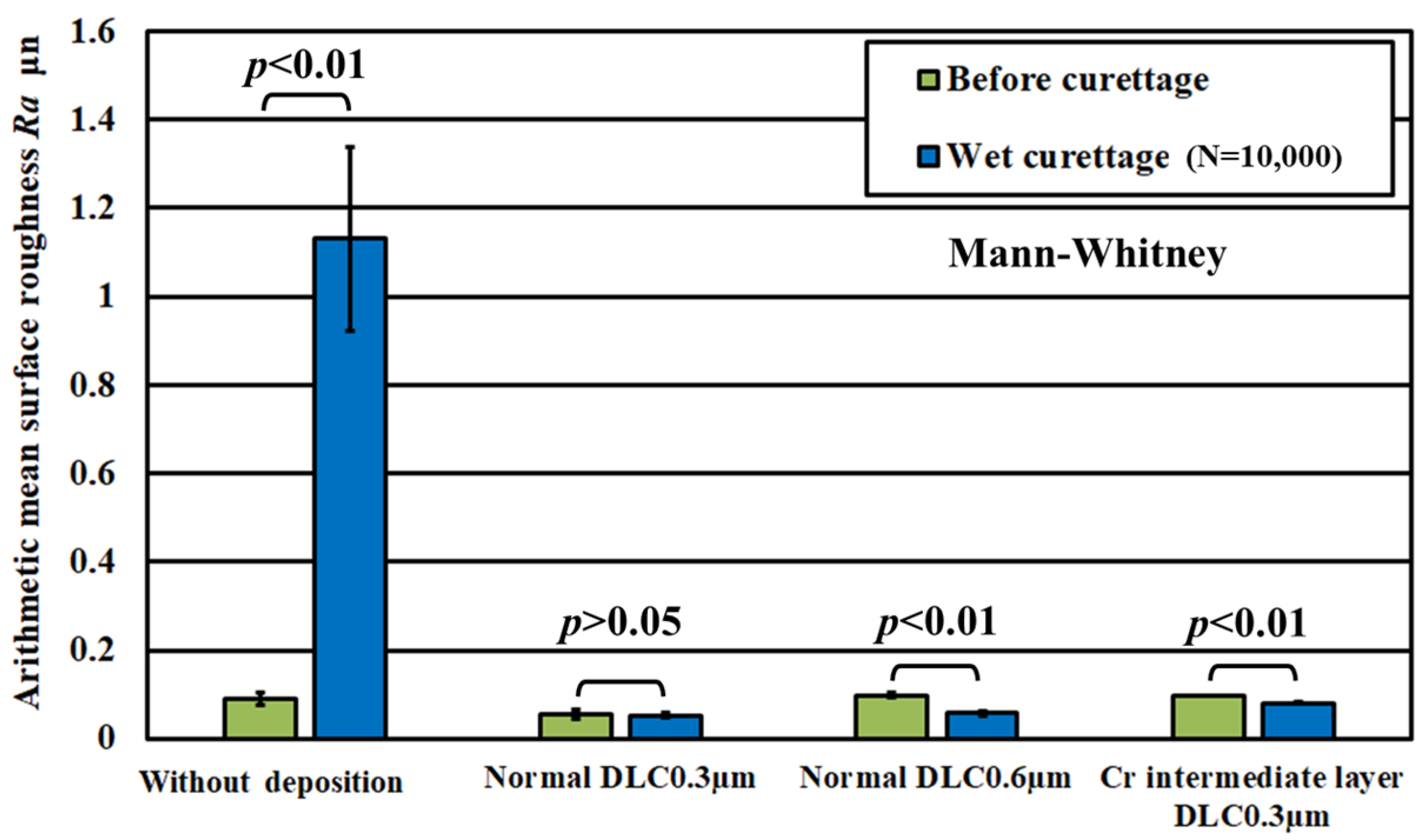
3.2. Lifetime Test Results by Wetting, Assuming an Oral Cavity
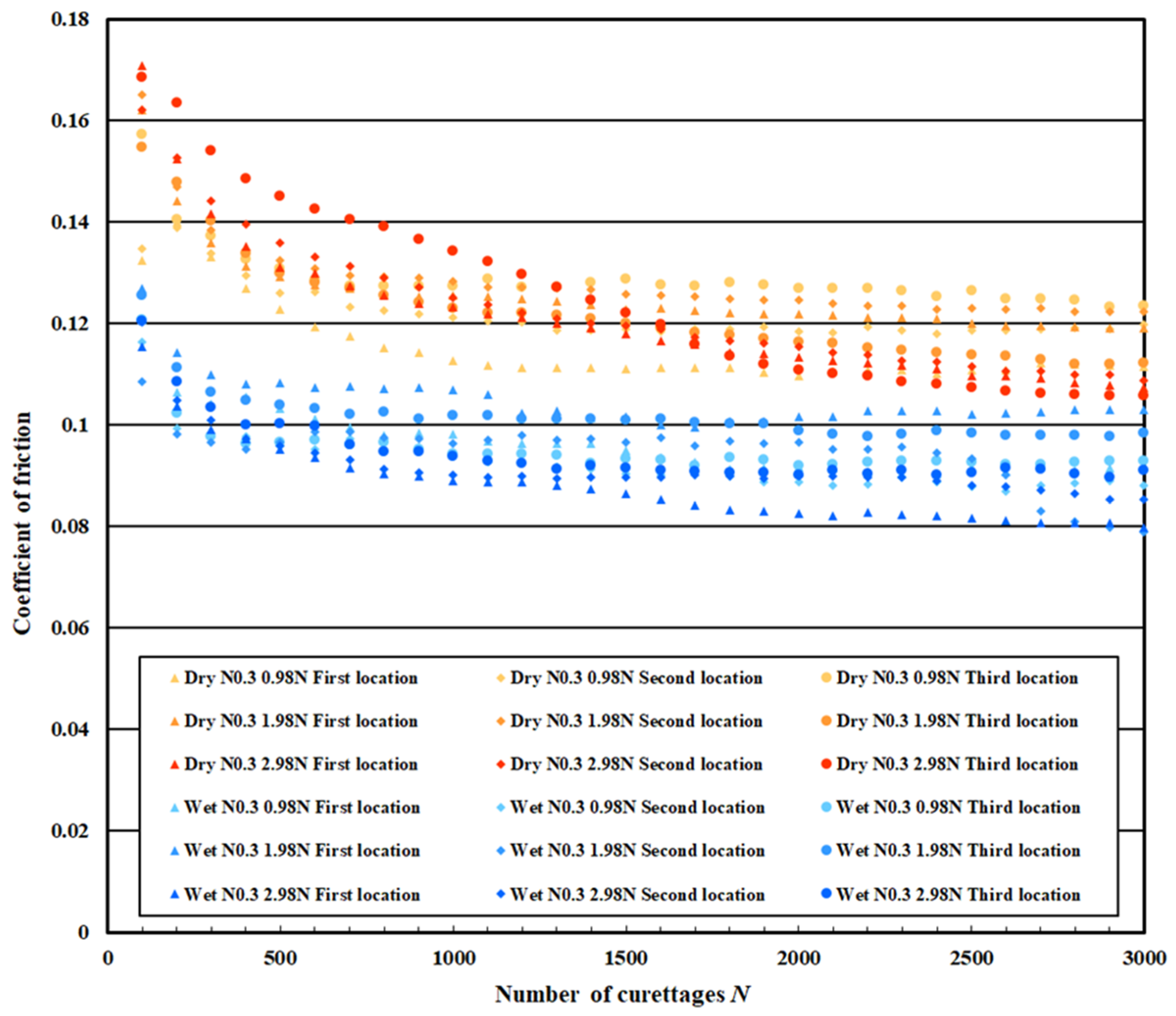
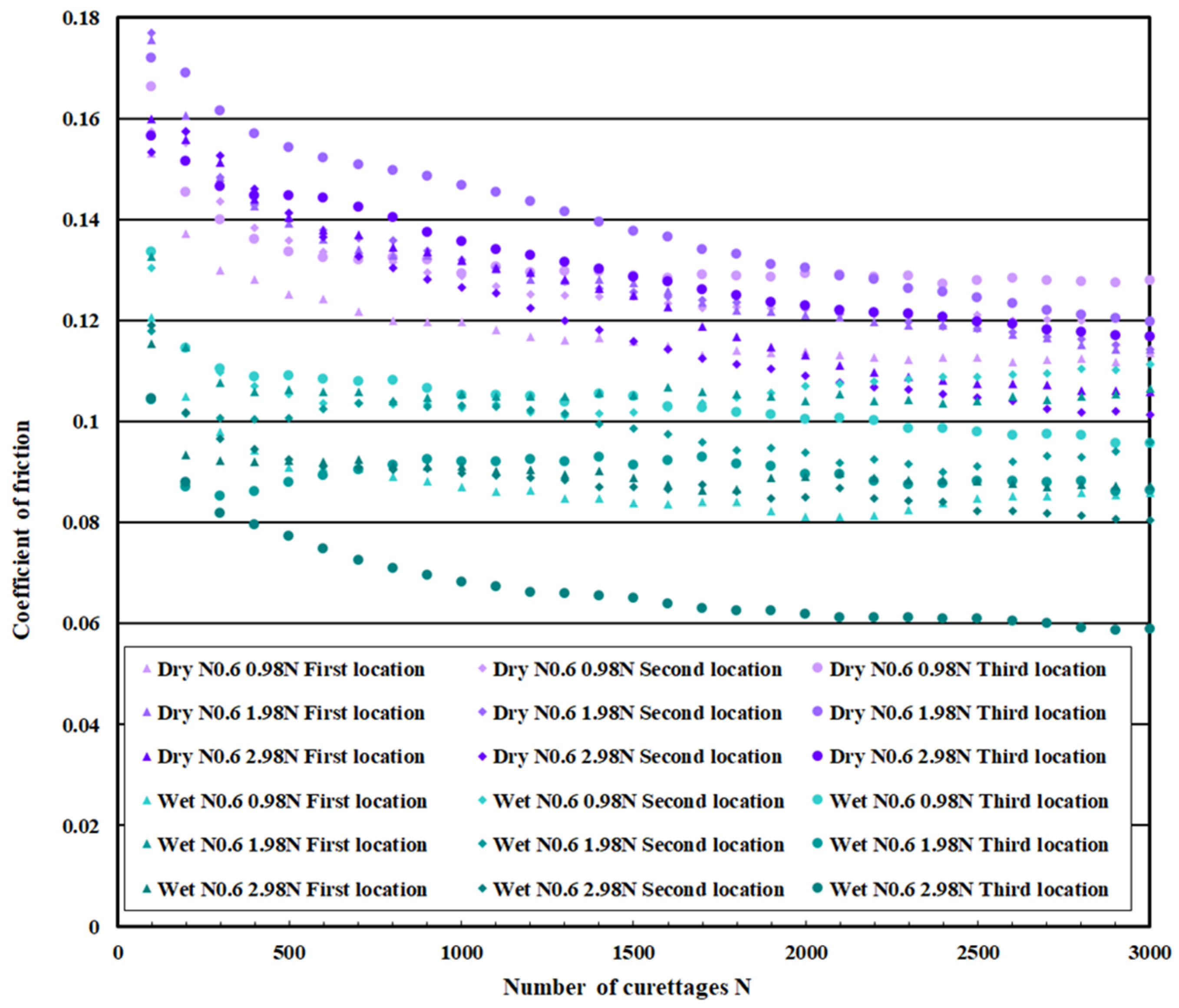
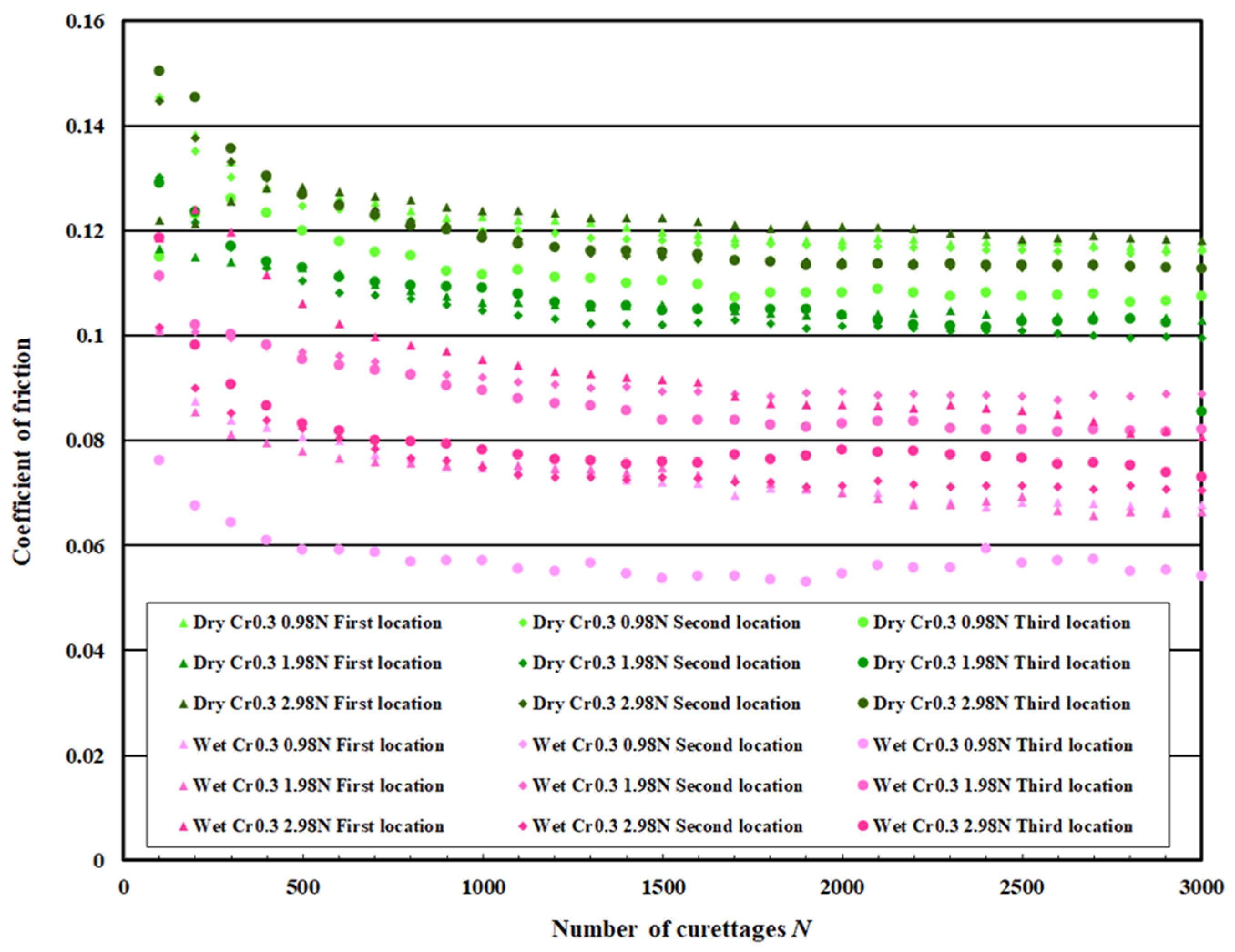
3.3. Coefficient of Friction Measurement Test Results
4. Discussion
5. Conclusions
Author Contributions
Funding
Institutional Review Board Statement
Informed Consent Statement
Data Availability Statement
Acknowledgments
Conflicts of Interest
References
- Taylor, T.D.; Agar, J.R. Twenty years of progress in implant prosthodontics. J. Prosthet. Dent. 2002, 88, 89–95. [Google Scholar] [CrossRef]
- Taylor, T.D.; Agar, J.R.; Vogiatzi, T. Implant prosthodontics: Current perspective and future directions. Int. J. Oral Maxillofac. Implant. 2000, 15, 66–75. [Google Scholar]
- Joda, T.; Ferrari, M.; Gallucci, G.O.; Wittneben, J.G.; Brägger, U. Digital technology in fixed implant prosthodontics. Periodontology 2000 2017, 73, 178–192. [Google Scholar] [CrossRef] [PubMed]
- Mombelli, A.; Müller, N.; Cionca, N. The epidemiology of peri-implantitis. Clin. Oral Implant. Res. 2012, 23, 67–76. [Google Scholar] [CrossRef] [PubMed]
- Diaz, P.; Gonzalo, E.; Villagra, L.J.G.; Miegimolle, B.; Suarez, M.J. What is the prevalence of peri-implantitis? A systematic review and meta-analysis. BMC Oral Health 2022, 22, 449. [Google Scholar] [CrossRef]
- Zitzmann, N.U.; Berglundh, T. Definition and prevalence of peri-implant diseases. J. Clin. Periodontol. 2008, 35, 286–291. [Google Scholar] [CrossRef]
- Dreyer, H.; Grischke, J.; Tiede, C.; Eberhard, J.; Schweitzer, A.; Toikkanen, S.E.; Glöckner, S.; Krause, G.; Stiesch, M. Epidemiology and risk factors of peri-implantitis: A systematic review. J. Periodontal Res. 2018, 53, 657–681. [Google Scholar] [CrossRef]
- Marcantonio, C.; Nicoli, L.G.; Marcantonio Junior, E.; Zandim-Barcelos, D.L. Prevalence and possible risk factors of peri-implantitis: A concept review. J. Contemp. Dent. Pract. 2015, 16, 750–757. [Google Scholar] [CrossRef]
- Salvi, G.E.; Cosgarea, R.; Sculean, A. Prevalence and mechanisms of peri-implant diseases. J. Dent. Res. 2017, 96, 31–37. [Google Scholar] [CrossRef]
- Koldsland, O.C.; Scheie, A.A.; Aass, A.M. Prevalence of peri-implantitis related to severity of the disease with different degrees of bone loss. J. Periodontol. 2010, 81, 231–238. [Google Scholar] [CrossRef]
- Tarnow, D.P. Increasing prevalence of peri-implantitis: How will we manage? J. Dent. Res. 2016, 95, 7–8. [Google Scholar] [CrossRef] [PubMed]
- Roccuzzo, A.; Stähli, A.; Monje, A.; Sculean, A.; Salvi, G.E. Peri-implantitis: A clinical update on prevalence and surgical treatment outcomes. J. Clin. Med. 2021, 10, 1107. [Google Scholar] [CrossRef] [PubMed]
- Lee, C.T.; Huang, Y.W.; Zhu, L.; Weltman, R. Prevalences of peri-implantitis and peri-implant mucositis: Systematic review and meta-analysis. J. Dent. 2017, 62, 1–12. [Google Scholar] [CrossRef] [PubMed]
- Song, X.; Li, L.; Gou, H.; Xu, Y. Impact of implant location on the prevalence of peri-implantitis: A systematic review and meta-analysis. J. Dent. 2020, 103, 103490. [Google Scholar] [CrossRef]
- Smeets, R.; Henningsen, A.; Jung, O.; Heiland, M.; Hammächer, C.; Stein, J.M. Definition, etiology, prevention and treatment of peri-implantitis—A review. Head Face Med. 2014, 10, 34. [Google Scholar] [CrossRef]
- Claffey, N.; Clarke, E.; Polyzois, I.; Renvert, S. Surgical treatment of peri-implantitis. J. Clin. Periodontol. 2008, 35, 316–332. [Google Scholar] [CrossRef]
- Esposito, M.; Grusovin, M.G.; Worthington, H.V. Treatment of peri-implantitis: What interventions are effective? A Cochrane systematic review. Eur. J. Oral Implantol. 2012, 5, S21–S41. [Google Scholar]
- Prathapachandran, J.; Suresh, N. Management of peri-implantitis. Dent. Res. J. (Isfahan) 2012, 9, 516–521. [Google Scholar] [CrossRef]
- Renvert, S.; Roos-Jansåker, A.M.; Claffey, N. Non-surgical treatment of peri-implant mucositis and peri-implantitis: A literature review. J. Clin. Periodontol. 2008, 35, 305–315. [Google Scholar] [CrossRef]
- Mahato, N.; Wu, X.; Wang, L. Management of peri-implantitis: A systematic review, 2010–2015. SpringerpPlus 2016, 5, 105. [Google Scholar] [CrossRef]
- Hauert, R. A review of modified DLC coatings for biological applications. Diam. Relat. Mater. 2003, 12, 583–589. [Google Scholar] [CrossRef]
- Thorwarth, G.; Falub, C.V.; Müller, U.; Weisse, B.; Voisard, C.; Tobler, M.; Hauert, R. Tribological behavior of DLC-coated articulating joint implants. Acta Biomater. 2010, 6, 2335–2341. [Google Scholar] [CrossRef] [PubMed]
- Choudhury, D.; Urban, F.; Vrbka, M.; Hartl, M.; Krupka, I. A novel tribological study on DLC-coated micro-dimpled orthopedics implant interface. J. Mech. Behav. Biomed. Mater. 2015, 45, 121–131. [Google Scholar] [CrossRef]
- Hauert, R. DLC films in biomedical applications. In Tribology of Diamond-Like Carbon Films: Fundamentals and Applications; Donnet, C., Erdemir, A., Eds.; Springer: Boston, MA, USA, 2008; pp. 494–509. [Google Scholar] [CrossRef]
- Rimondini, L.; Farè, S.; Brambilla, E.; Felloni, A.; Consonni, C.; Brossa, F.; Carrassi, A. The effect of surface roughness on early in vivo plaque colonization on titanium. J. Periodontol. 1997, 68, 556–562. [Google Scholar] [CrossRef]
- Hossain, A.; Okawa, S.; Miyakawa, O. Effect of toothbrushing on titanium surface: An approach to understanding surface properties of brushed titanium. Dent. Mater. 2006, 22, 346–352. [Google Scholar] [CrossRef]
- Park, J.B.; Jang, Y.J.; Koh, M.; Choi, B.K.; Kim, K.K.; Ko, Y. In vitro analysis of the efficacy of ultrasonic scalers and a toothbrush for removing bacteria from resorbable blast material titanium disks. J. Periodontol. 2013, 84, 1191–1198. [Google Scholar] [CrossRef]
- Park, J.B.; Kim, N.R.; Ko, Y. Effects of ultrasonic scaler tips and toothbrush on titanium disc surfaces evaluated with confocal microscopy. J. Craniofac. Surg. 2012, 23, 1552–1558. [Google Scholar] [CrossRef]
- Zhang, J.; Lou, J.; He, H.; Xie, Y. Comparative investigation on the tribological performances of TiN, TiCN, and Ti-DLC film-coated stainless steel. JOM 2019, 71, 4872–4879. [Google Scholar] [CrossRef]
- Cui, L.; Guoqing, L.; Wenwu, C.; Zongxin, M.; Chengwu, Z.; Liang, W. The study of doped DLC films by Ti ion implantation. Thin Solid Film. 2005, 475, 279–282. [Google Scholar] [CrossRef]
- Dai, W.; Ke, P.; Wang, A. Microstructure and property evolution of Cr-DLC films with different Cr content deposited by a hybrid beam technique. Vacuum 2011, 85, 792–797. [Google Scholar] [CrossRef]
- Al Mahmud, K.A.H.; Kalam, M.A.; Masjuki, H.H.; Mobarak, H.M.; Zulkifli, N.W.M. An updated overview of diamond-like carbon coating in tribology. Crit. Rev. Solid State Mater. Sci. 2015, 40, 90–118. [Google Scholar] [CrossRef]
- Zou, C.W.; Wang, H.J.; Feng, L.; Xue, S.W. Effects of Cr concentrations on the microstructure, hardness, and temperature-dependent tribological properties of Cr-DLC coatings. Appl. Surf. Sci. 2013, 286, 137–141. [Google Scholar] [CrossRef]


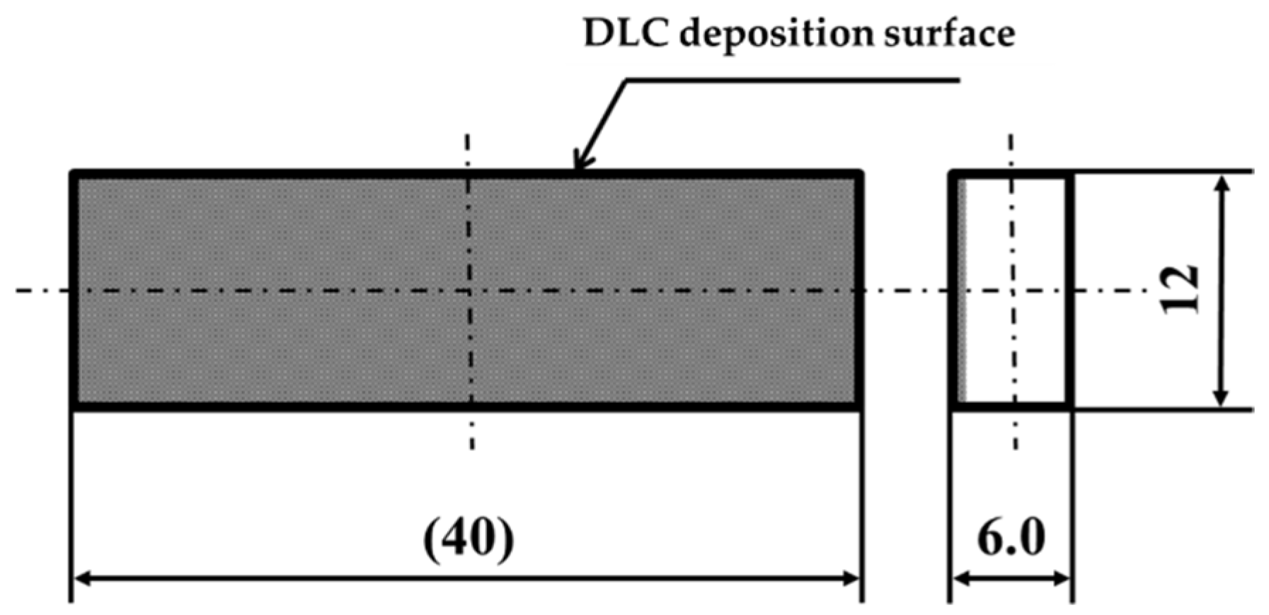
| Specimen | Without deposition, pure titanium Normal DLC 0.3 μm Normal DLC 0.6 μm Cr intermediate layer DLC 0.3 μm |
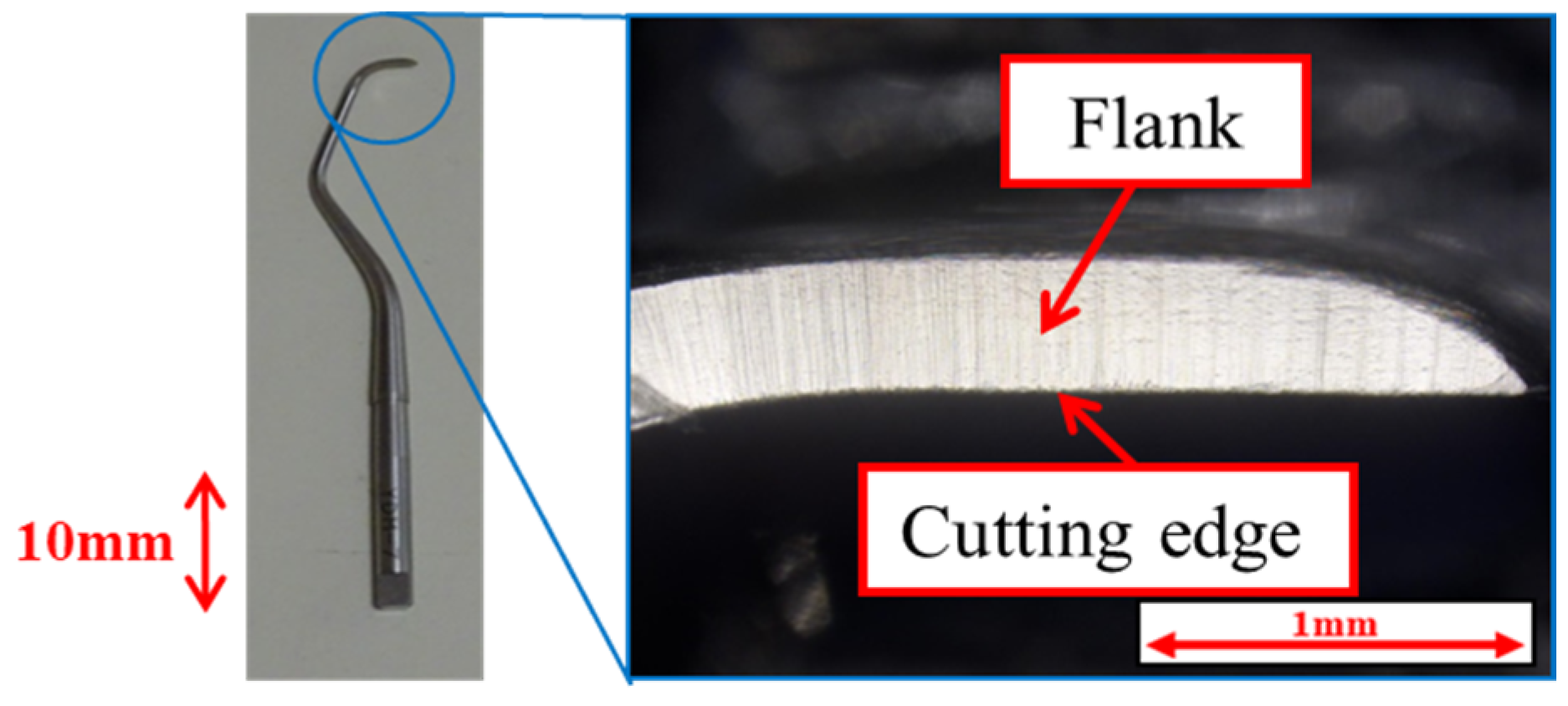
| Scaler | Gracey-type curette type #G7 |
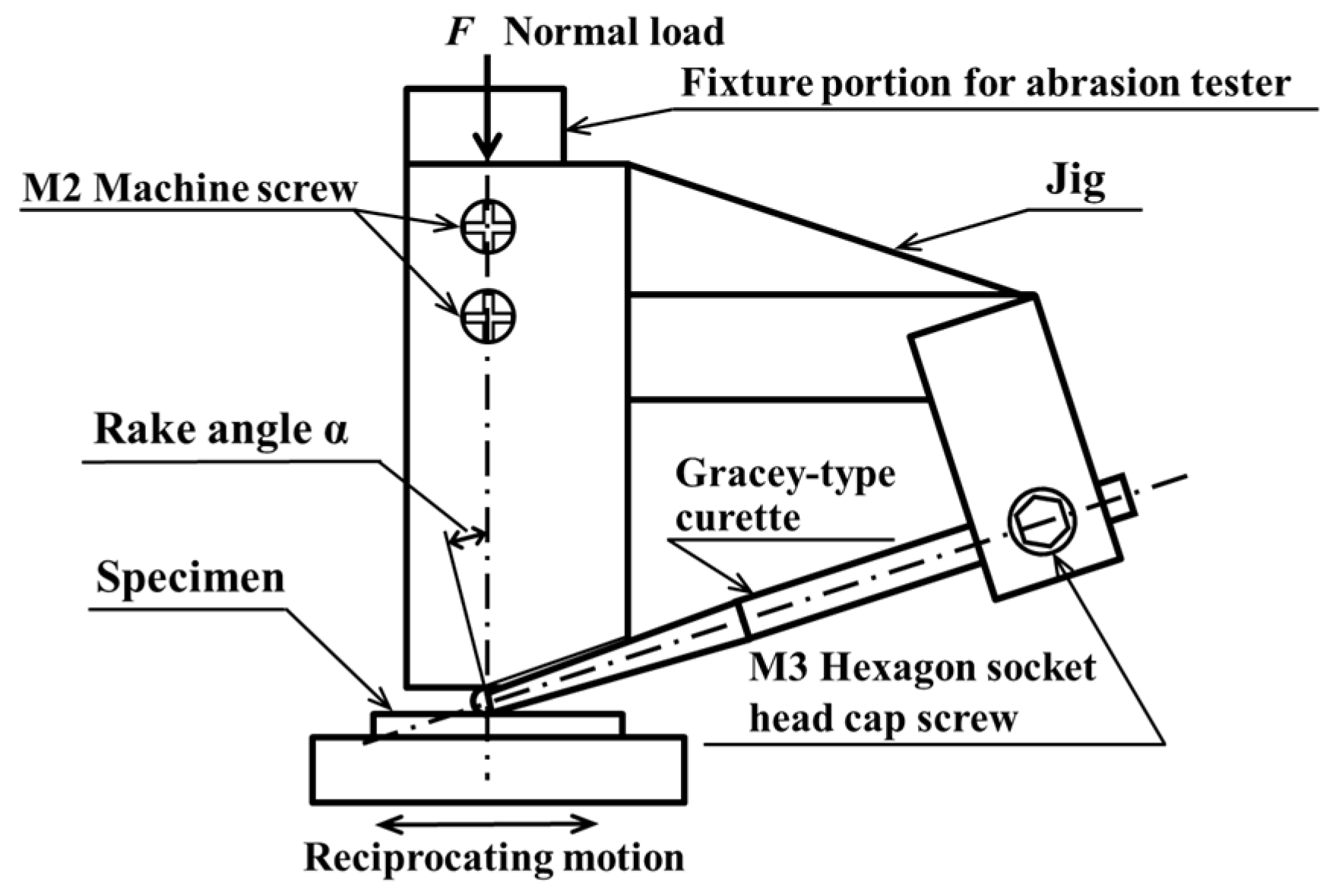
| Normal force, F N | 3.9 |
| Rake angle, α degree | 10 |
| Number of curettages, N times | 1 × 10³, 3 × 10³, 4 × 10³, 1 × 10⁴ |
| Curettage length, L mm | 3 |
| Curettage direction | Reciprocating motion |
| Specimen | Without deposition, pure titanium Normal DLC 0.3 μm Normal DLC 0.6 μm Cr intermediate layer DLC 0.3 μm |
| Scaler | Gracey-type curette type #G7 |
| Normal force, F N | 3.9 |
| Rake angle, α degree | 10 |
| Number of curettages, N times | 1 × 10⁴ |
| Curettage length, L mm | 3 |
| Flow rate, m3/s | 4 × 10⁻⁶ |
| Curettage direction | Reciprocating motion |
| Specimen | Without deposition, pure titanium Normal DLC 0.3 μm Normal DLC 0.6 μm Cr intermediate layer DLC 0.3 μm |
| Scaler | Gracey-type curette type #G7 |
| Normal force, F N | 0.98, 1.98, 2.98 |
| Rake angle, α degree | 10 |
| Number of curettages, N times | 3 × 10³ |
| Curettage length, L mm | 3 |
| Curettage fluid | Dry Wet (curettage was performed while water was dripped onto the specimen surface) |
| Curettage direction | Reciprocating motion |
| Normal DLC 0.3 μm | Dry curettage | Wet curettage | ||||
| F = 0.98 N | F = 1.98 N | F = 2.98 N | F = 0.98 N | F = 1.98 N | F = 2.98 N | |
| N = 0~100 | 0.14 | 0.16 | 0.17 | 0.12 | 0.12 | 0.12 |
| N = 2.5~3 × 10³ | 0.12 | 0.12 | 0.11 | 0.10 | 0.110 | 0.09 |
| Normal DLC 0.6 μm | Dry curettage | Wet curettage | ||||
| F = 0.98 N | F = 1.98 N | F = 2.98 N | F = 0.98 N | F = 1.98 N | F = 2.98 N | |
| N = 0~100 | 0.16 | 0.18 | 0.16 | 0.13 | 0.12 | 0.11 |
| N = 2.5~3 × 10³ | 0.12 | 0.12 | 0.11 | 0.10 | 0.10 | 0.08 |
| DLC 0.3 μm with Cr intermediate layer | Dry curettage | Wet curettage | ||||
| F = 0.98 N | F = 1.98 N | F = 2.98 N | F = 0.98 N | F = 1.98 N | F = 2.98 N | |
| N = 0~100 | 0.14 | 0.13 | 0.14 | 0.09 | 0.11 | 0.11 |
| N = 2.5~3 × 10³ | 0.11 | 0.10 | 0.12 | 0.06 | 0.08 | 0.08 |
Disclaimer/Publisher’s Note: The statements, opinions and data contained in all publications are solely those of the individual author(s) and contributor(s) and not of MDPI and/or the editor(s). MDPI and/or the editor(s) disclaim responsibility for any injury to people or property resulting from any ideas, methods, instructions or products referred to in the content. |
© 2025 by the authors. Licensee MDPI, Basel, Switzerland. This article is an open access article distributed under the terms and conditions of the Creative Commons Attribution (CC BY) license (https://creativecommons.org/licenses/by/4.0/).
Share and Cite
Sato, H.; Kameyama, Y.; Yoshikawa, R.; Tabuchi, K.; Ogata, C.; Komasa, S. Effect of Diamond-like Carbon Thin-Film Deposition on the Hardness of Pure Titanium Surfaces. Materials 2025, 18, 2992. https://doi.org/10.3390/ma18132992
Sato H, Kameyama Y, Yoshikawa R, Tabuchi K, Ogata C, Komasa S. Effect of Diamond-like Carbon Thin-Film Deposition on the Hardness of Pure Titanium Surfaces. Materials. 2025; 18(13):2992. https://doi.org/10.3390/ma18132992
Chicago/Turabian StyleSato, Hideaki, Yutaka Kameyama, Ryota Yoshikawa, Kaito Tabuchi, Chizuko Ogata, and Satoshi Komasa. 2025. "Effect of Diamond-like Carbon Thin-Film Deposition on the Hardness of Pure Titanium Surfaces" Materials 18, no. 13: 2992. https://doi.org/10.3390/ma18132992
APA StyleSato, H., Kameyama, Y., Yoshikawa, R., Tabuchi, K., Ogata, C., & Komasa, S. (2025). Effect of Diamond-like Carbon Thin-Film Deposition on the Hardness of Pure Titanium Surfaces. Materials, 18(13), 2992. https://doi.org/10.3390/ma18132992