
Mechanical Properties of Repaired Welded Pipe Joints Made of Heat-Resistant Steel P92


 ,
,  , , , and
Highlights
- Mechanical properties and microstructural evolution of P92 heat-resistant steel after both initial and simulated repair welding, highlighting the impact of crucial welding parameters.
- Comparative analysis of microstructure and mechanical properties (tensile strength, impact toughness, microhardness) of initially welded and repair-welded joints of pipe.
- Repair welding can significantly change existing weld metal and heat-affected zone microstructures.
- A key recommendation for repair welding is to use a strictly defined heat input.
- Insights for optimizing welding and repair-welding procedures for P92 steel, in the terms of interaction/mutual dependence between welding parameters, microstructure, and mechanical properties.
Abstract
1. Introduction
- (a)
- Operational conditions exceeding design limits;
- (b)
- Inadequate structural design and poor material selection; and
- (c)
- Extensive repair welding procedures that introduce excessive heat and cause subsequent material degradation.
2. Heat-Resistant Steel P92
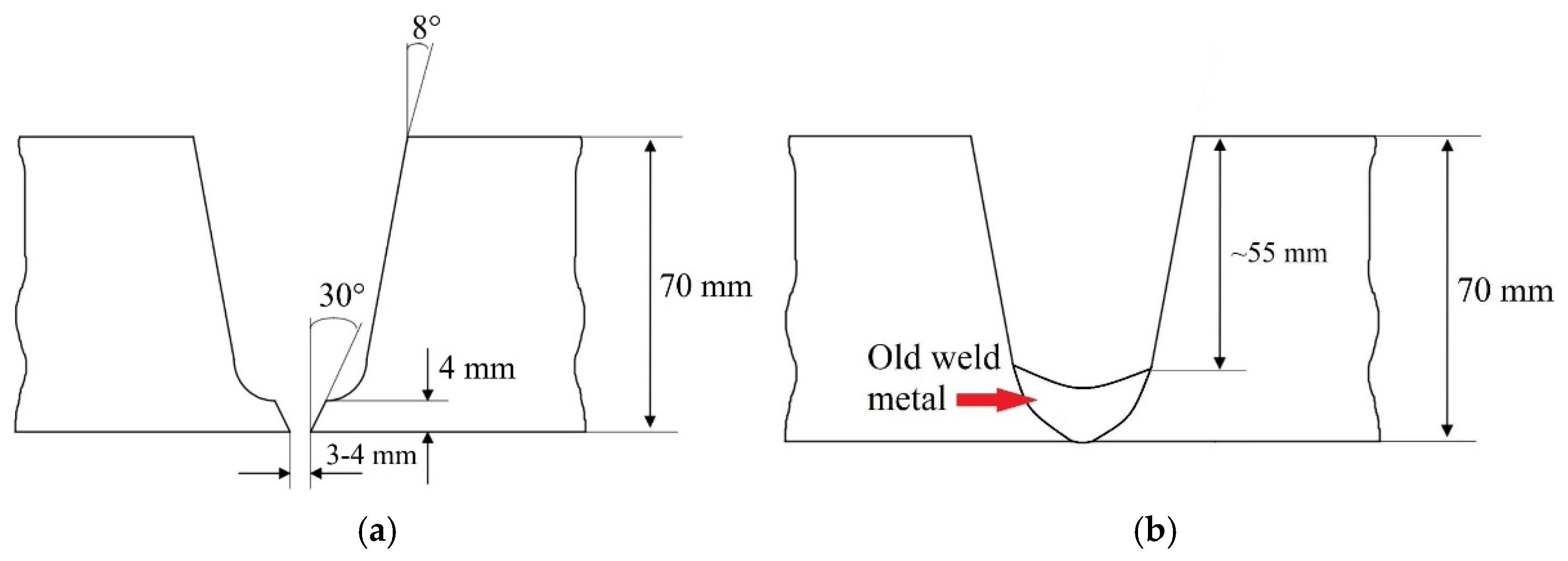
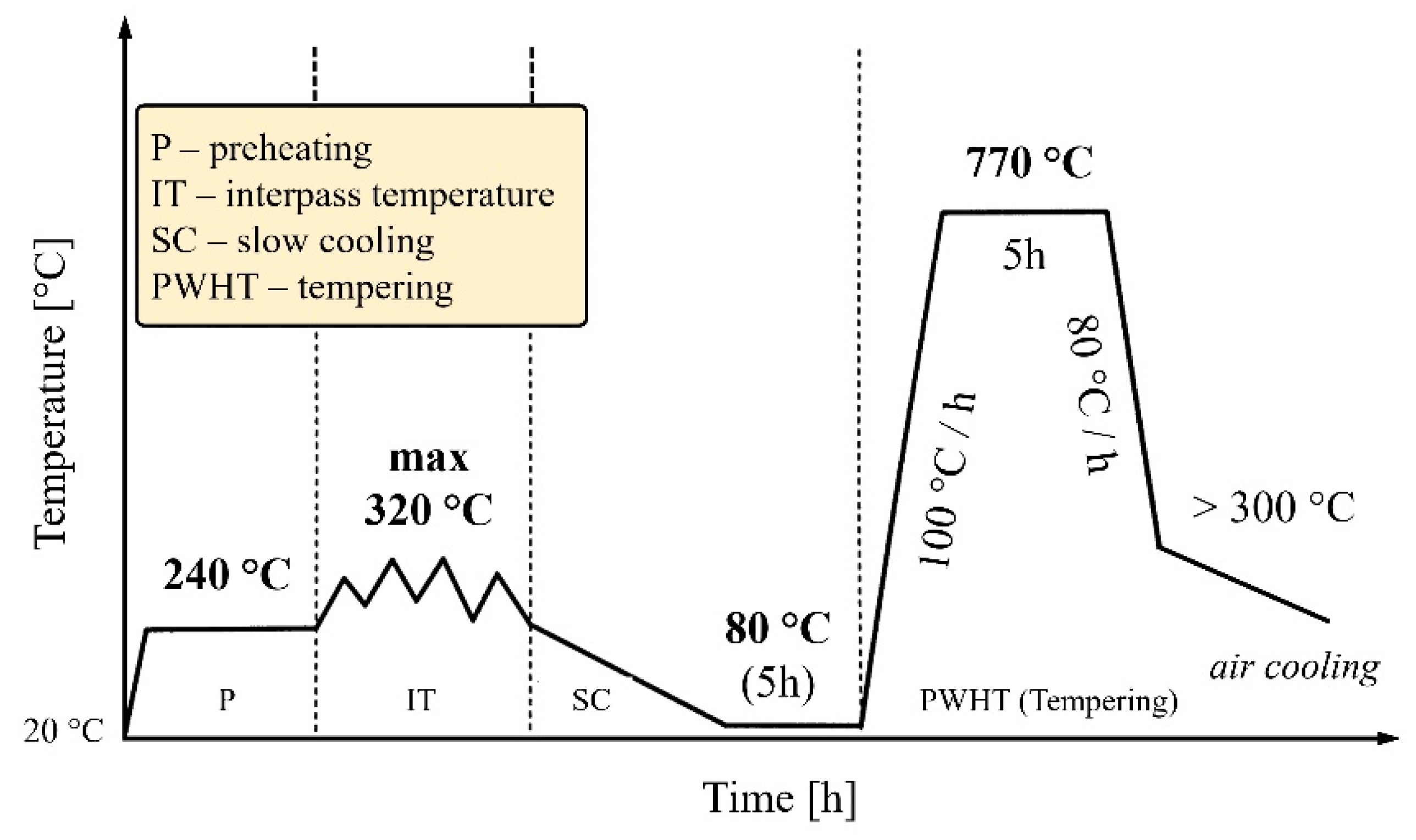
3. Welding and Repair Welding
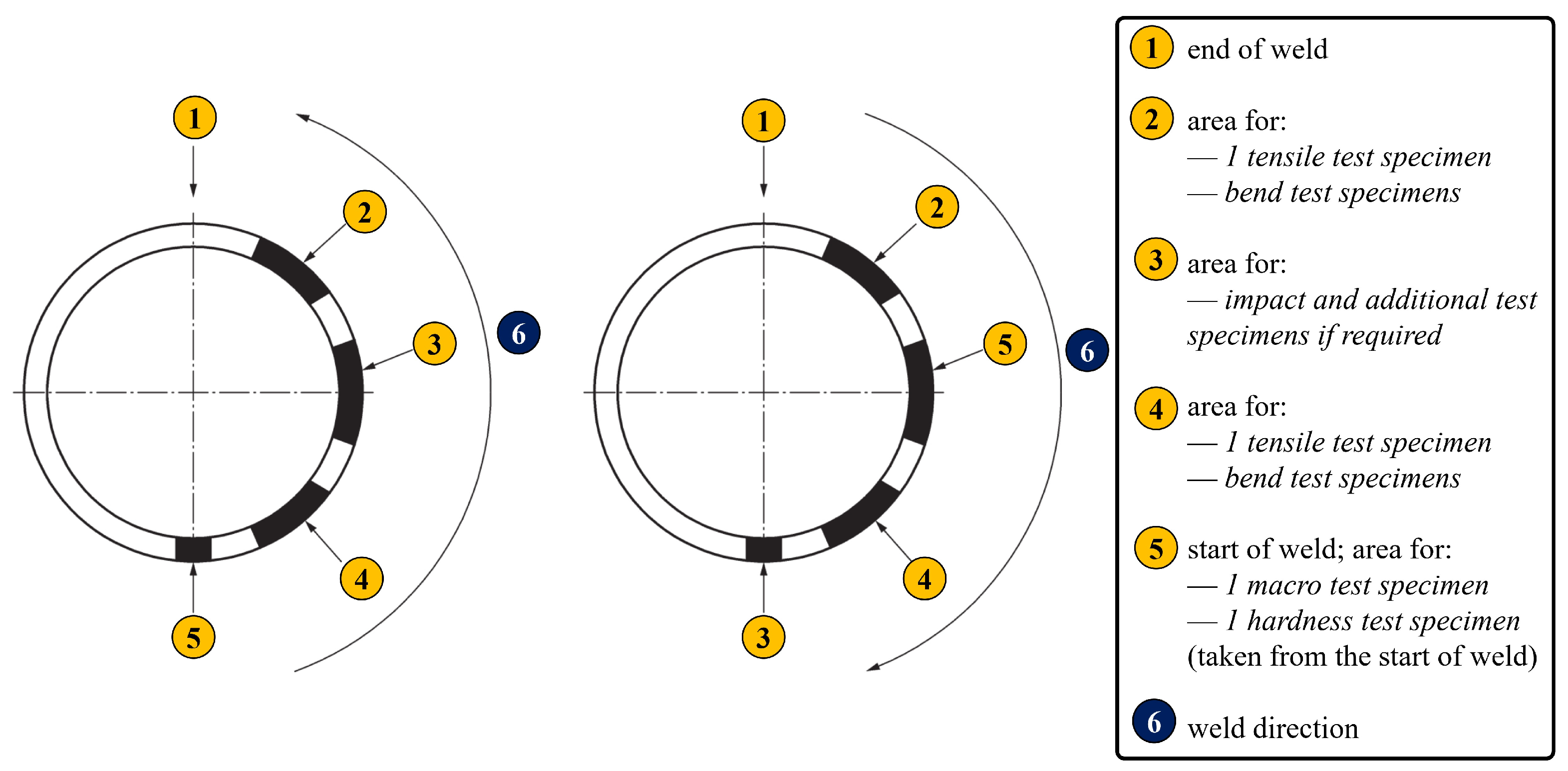
4. Experimental Testing
4.1. Tensile Testing
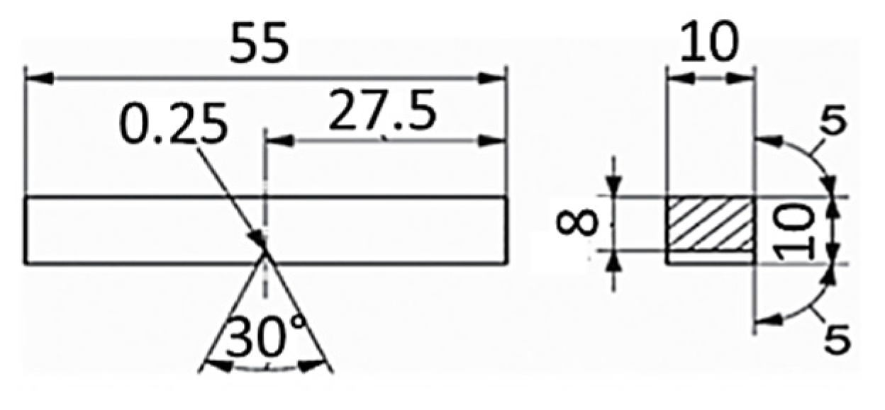
4.2. Charpy Impact Testing
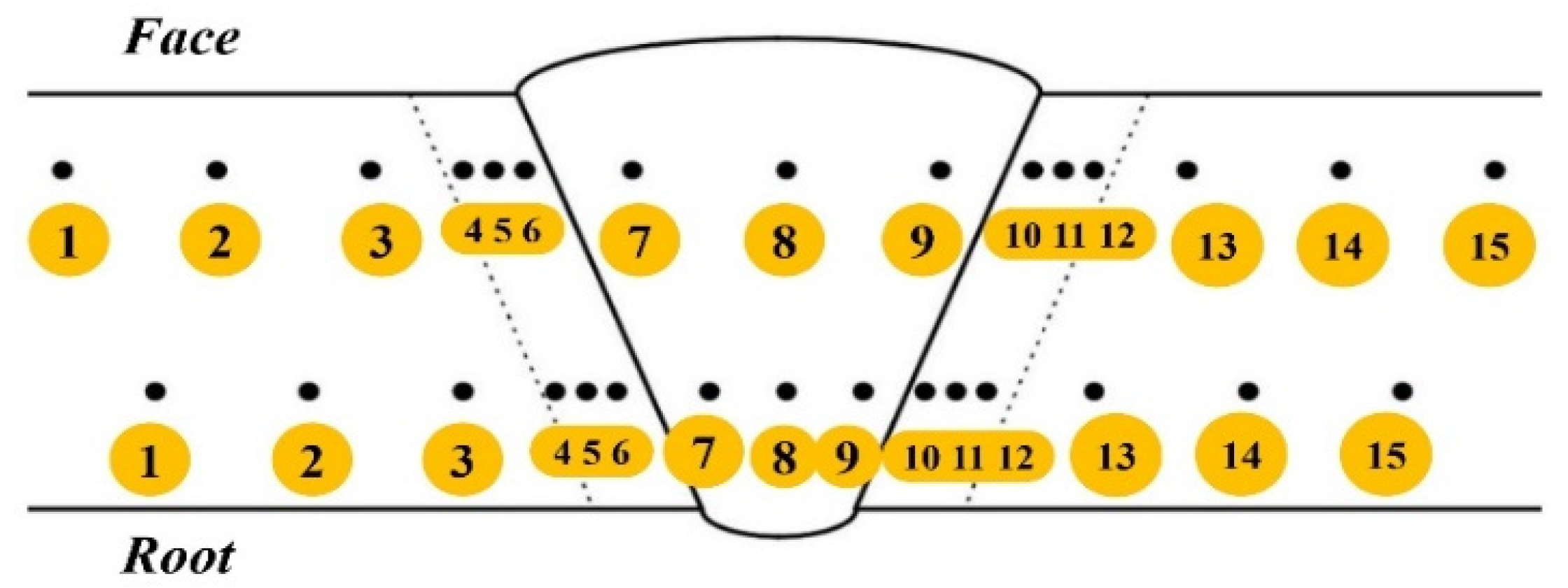
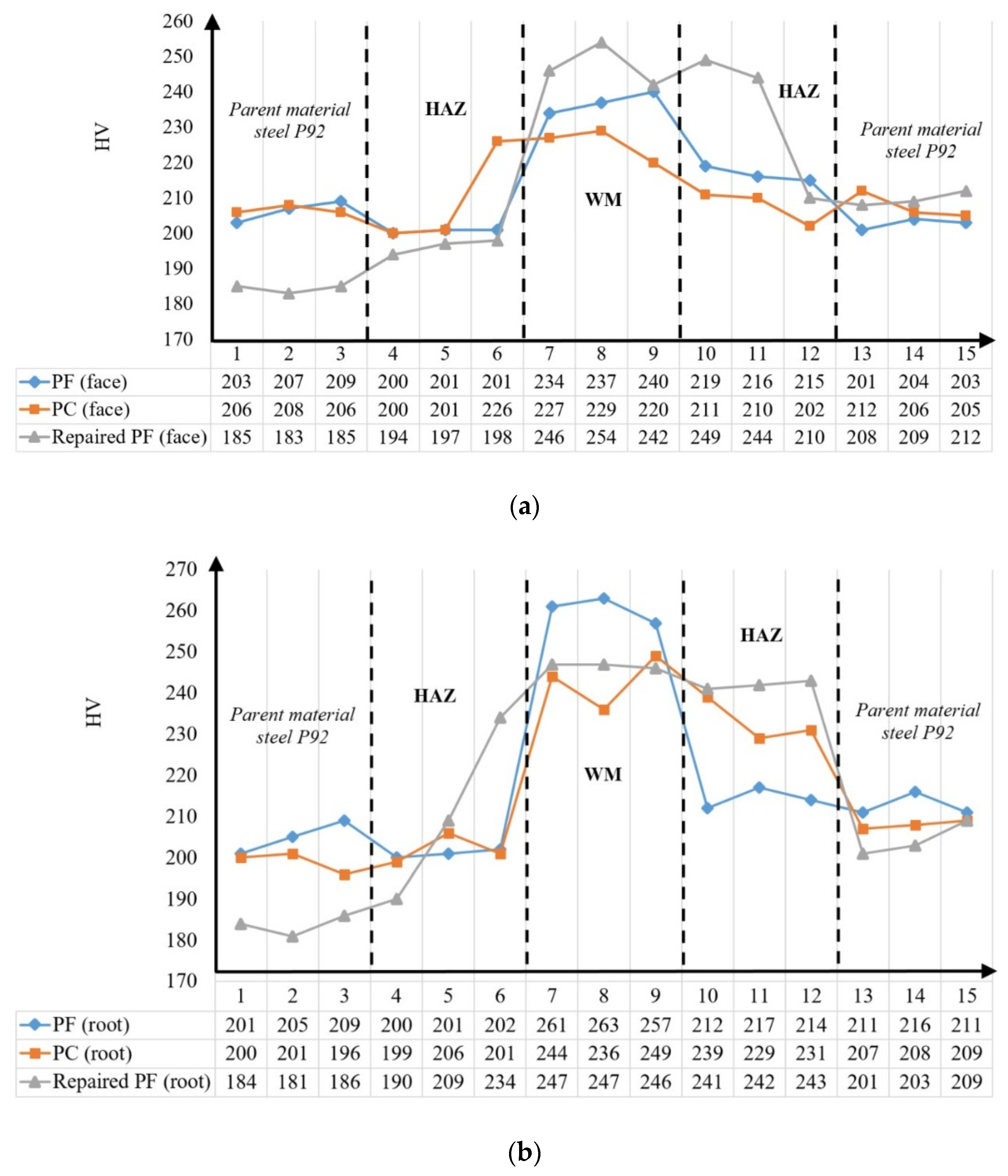
4.3. Hardness Measuring
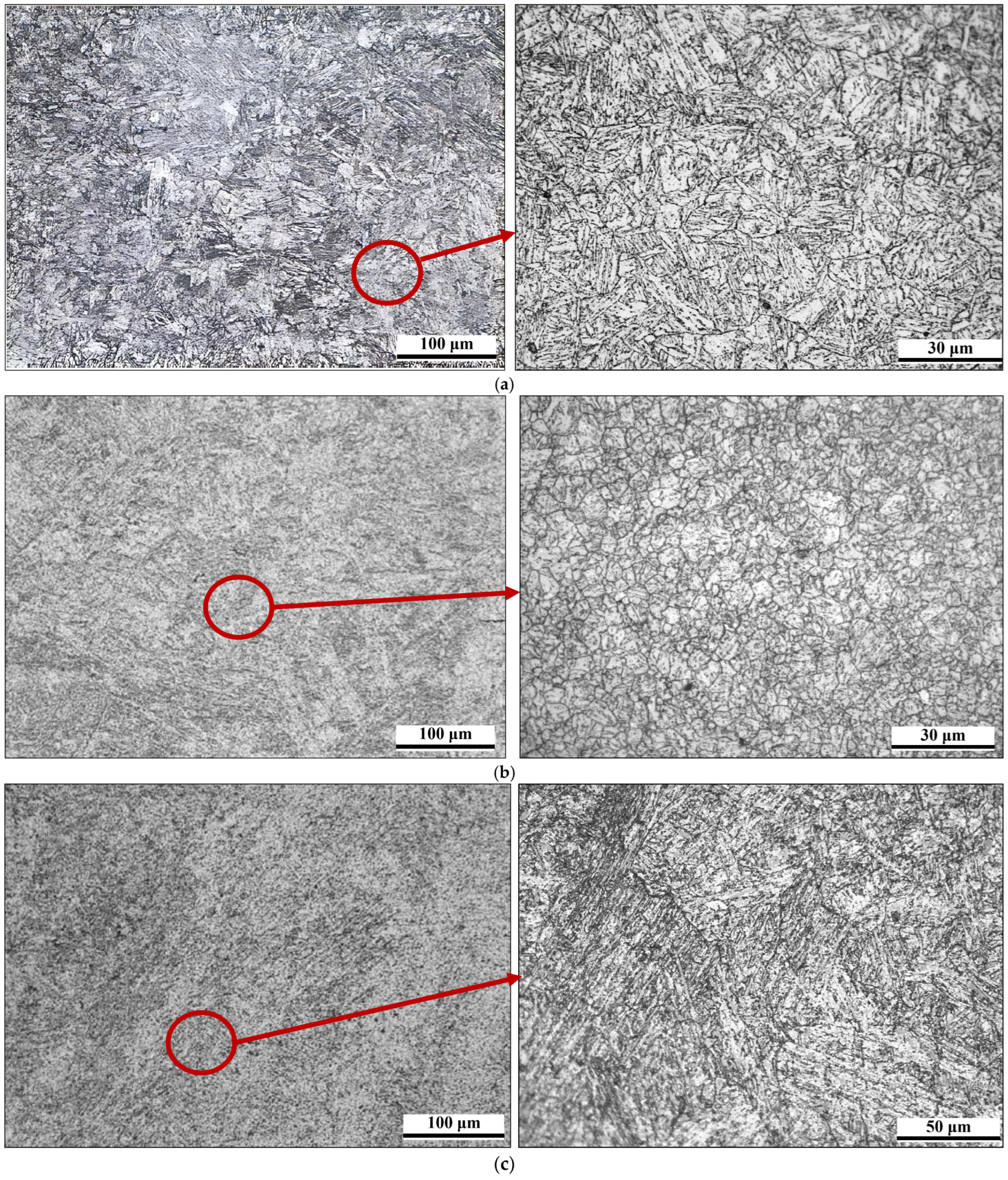
5. Microstructural Analysis
6. Discussion
- Appropriate welding and repair techniques with recommended welding parameters, leading to defining an appropriate welding procedure specification (which has to be carried out at room temperature).
- The aforementioned led to satisfactory mechanical properties of the welds at room temperature, supported by favorable microstructures within each welded joint zone for every welded pipe case. Nevertheless, the effect of heat input (due to welding or post-weld heat treatment) on these properties, particularly concerning the WM and HAZ, warrants a comprehensive investigation at higher temperatures.
- Identification of potentially critical spots during the welding of P92 steel and subsequent repair welding, based on an analysis of mechanical properties and metallographic analysis.
- The necessity of utilizing more advanced techniques for full characterization of each welded joint zone, which is crucial for elevated temperature applications. This predominantly refers to metallographic analysis.
7. Conclusions
- Tensile testing revealed that fractures occurred consistently in the parent material, indicating an overmatching effect.
- The repaired (PF3) welded joints have lower ultimate tensile strength compared to the PF1 and PC2 welded ones, which can be attributed to microstructural changes induced by the additional heat input during the repair welding and PWHT, affecting the tempering of the martensite.
- Impact testing demonstrated that specimens with the notch in the HAZ exhibited higher impact energy values, suggesting that specific microstructural features within the HAZ (likely related to grain refinement or tempering effects) contribute to improved toughness compared to the WM. Another thermal cycle due to repair welding also contributes to this statement, since the average impact energy of repaired welded pipe is higher than both original welded ones.
- In the repair-welded case, a slight increase in hardness was noted in the WM and HAZ, likely due to the supplementary heat input and PWHT contributing to further microstructural changes.
Author Contributions
Funding
Institutional Review Board Statement
Informed Consent Statement
Data Availability Statement
Conflicts of Interest
References
- Jovanović, A.; Bakić, G.; Golubović, T.; Kirin, S.; Sedmak, A. Integrity And Risk Assessment Of Reconstructed Steam Line. Struct. Integr. Life 2023, 23, 367–371. [Google Scholar]
- Xia, X.; Zhu, B.; Jin, X.; Tang, M.; Yang, L.; Xue, F.; Shi, J.; Zhang, G. Analysis on microstructure and properties evolution and life prediction of P92 steel in high temperature service. Int. J. Press. Vessel. Pip. 2021, 194 Pt A, 104482. [Google Scholar] [CrossRef]
- Chu, Q.; Zhang, M.; Li, J.; Chen, Y.; Luo, H.; Wang, Q. Failure analysis of a steam pipe weld used in power generation plant. Eng. Fail. Anal. 2014, 44, 363–370. [Google Scholar] [CrossRef]
- Auerkari, P.; Salonen, J.; Holmström, S.; Laukkanen, A.; Rantala, J.; Nikkarila, R. Creep damage and long term life modelling of an X20 steam line component. Eng. Fail. Anal. 2013, 35, 508–515. [Google Scholar] [CrossRef]
- Vodárek, V.; Holešinský, J.; Kuboň, Z.; Palupčíková, R.; Váňová, P.; Malcharcziková, J. Creep Resistance and Microstructure Evolution in P23/P91 Welds. Materials 2025, 18, 194. [Google Scholar] [CrossRef] [PubMed]
- Yang, C.; Shi, R.; Qiao, J. Creep behavior and microstructure evolution of creep cavities in the heat-affected zone of P92 steel joints. Int. J. Press. Vessel. Pip. 2025, 216, 105512. [Google Scholar] [CrossRef]
- Zeman, B.M. Wrong heat treatment of martensitic steel welded tubes caused major cracking during assembly of resuperheaters in a fossil fuel power plant. Eng. Fail. Anal. 2003, 10, 569–579. [Google Scholar] [CrossRef]
- Vučetić, F.; Đorđević, B.; Aranđelović, M.; Sedmak, S.; Milošević, N.; Radu, D.; Jeremić, L. Integrity of Welded Joints Made of Alloy NiCr21Mo. Struct. Integr. Life 2023, 23, 91–97. [Google Scholar]
- Kumar, A.; Pandey, C. Structural integrity assessment of Inconel 617/P92 steel dissimilar welds for different groove geometry. Sci. Rep. 2023, 13, 8061. [Google Scholar] [CrossRef]
- Vaillant, J.C.; Vandenberghe, B.; Hahn, B.; Heuser, H.; Jochum, C. T/P23, 24, 911 and 92: New grades for advanced coal-fired power plants—Properties and experience. Int. J. Press. Vessel. Pip. 2008, 85, 38–46. [Google Scholar] [CrossRef]
- Tang, L.; Yang, Z.; Cui, X.; Zhang, L.; Li, J. Study on Mechanical and Microstructural Evolution of P92 Pipes During Long-Time Operation. Materials 2024, 17, 5092. [Google Scholar] [CrossRef] [PubMed]
- Kaplan, E.; Atici, T. Properties And Weldability Of X10CrWMoVNb9-2 (P92) Steel. In Proceedings of the International Institute of Welding International Conference 2010, Istanbul, Turkey, 11–17 July 2010. [Google Scholar]
- Wang, Y.; Qin, N.; Shang, J.; Yang, J.; Sun, B. Study on Microstructure and Properties of P92 Steel Joint with Narrow Gap Automatic Welding, Journal of Physics: Conference Series. In Proceedings of the 2nd International Conference on Advances in Modern Physics Sciences and Engineering Technology 2023, Wuhan, China, 29–30 November 2023; Volume 2549, pp. 29–30. [Google Scholar] [CrossRef]
- Kumar, A.; Pandey, C. Development and Evaluation of Dissimilar Gas Tungsten Arc-Welded Joint of P92 Steel/Inconel 617 Alloy for Advanced Ultra-Supercritical Boiler Applications. Metall. Mater. Trans. A 2022, 53, 3245–3273. [Google Scholar] [CrossRef]
- Li, S.; Li, J.; Sun, G.; Deng, D. Modeling of welding residual stress in a dissimilar metal butt-welded joint between P92 ferritic steel and SUS304 austenitic stainless steel. J. Mater. Res. Technol. 2023, 23, 4938–4954. [Google Scholar] [CrossRef]
- Kumar, A.; Guguloth, K.; Pandey, S.M.; Sirohi, S.; Świerczyńska, A.; Fydrych, D.; Pandey, C. Microstructure degradation and creep failure study of the dissimilar metal welded joint of heat-resistant steel and Inconel 617 alloy tested at 650 °C and applied stress range of 100–150 Mpa. Int. J. Press. Vessel. Pip. 2025, 214, 105370. [Google Scholar] [CrossRef]
- Dak, G.; Guguloth, K.; Vidyarthy, R.S. Creep rupture study of dissimilar welded joints of P92 and 304L steels. Weld. World 2024, 68, 2995–3018. [Google Scholar] [CrossRef]
- Li, M.; Liu, Z.; Lu, Z.; Pan, W.; Xue, H.; Shang, Y. Analysis of the Creep Failure of P92/HR3C Dissimilar Steel Welded Joint. Journal of Physics: Conference Series. In Proceedings of the 10th International Conference on Advanced Manufacturing Technology and Materials Engineering 2023, Zhuhai, China, 25–27 March 2023; Volume 2566. [Google Scholar] [CrossRef]
- Xue, W.; Qian-gang, P.; Zhi-jun, L.; Hui-qiang, Z.; Yong-shun, T. Creep rupture behaviour of P92 steel weldment. Eng. Fail. Anal. 2011, 18, 186–191. [Google Scholar] [CrossRef]
- Yangyang, F. Comparative study on microstructure and hardness of P92 steel before and after long service, Journal of Physics: Conference Series. In Proceedings of the 4th International Conference on Advanced Materials and Intelligent Manufacturing 2023, Guangzhou, China, 1–3 December 2023; Volume 2720. [Google Scholar] [CrossRef]
- Duan, P.; An, D.; Liu, Z.; Li, J.; Cheng, Y.; Li, B.; Wang, S. Effect of Long-Term Thermal Aging at 680 °C on Microstructure and Mechanical Properties of P92 Steel. J. Mater. Eng. Perform. 2024, 33, 1448–1456. [Google Scholar] [CrossRef]
- Zielinski, A.; Golanski, G.; Sroka, M. Assessment of microstructure stability and mechanical properties of X10CrWMoVNb9-2 (P92) steel after long-term thermal ageing for high-temperature applications. Kov. Mater. Met. Mater. 2016, 54, 61–70. [Google Scholar] [CrossRef]
- Zhou, Y.; Zhao, Q.; Lu, J.; Liang, Z.; Yuan, Y.; Gu, Y.; Huang, J. Steam oxidation of scratched β-FeAl coatings on P92 steel. Mater. Corros. 2022, 74, 197–208. [Google Scholar] [CrossRef]
- Kral, P.; Dvorak, J.; Sklenicka, V.; Horita, Z.; Takizawa, Y.; Tang, Y.; Kuncická, L.; Kvapilova, M.; Ohankova, M. Influence of High Pressure Sliding and Rotary Swagingon Creep Behavior of P92 Steel at 500 °C. Metals 2021, 11, 2044. [Google Scholar] [CrossRef]
- Parker, J.; Siefert, J. Manufacture and Performance of Welds in Creep Strength Enhanced Ferritic Steels. Materials 2019, 12, 2257. [Google Scholar] [CrossRef] [PubMed]
- Sattar, M.; Othman, A.R.; Kamaruddin, S.; Akhtar, M.; Khan, A. Limitations on the computational analysis of creep failure models, A review. Eng. Fail. Anal. 2022, 134, 105968. [Google Scholar] [CrossRef]
- Milović, L. Significance Of Cracks In The Heat-Affected-Zone Of Steels For Elevated Temperature Application. Struct. Integr. Life 2008, 8, 55–64. [Google Scholar]
- Zhao, L.; Jing, H.; Xu, L.; Han, Y.; Xiu, J. Experimental study on creep damage evolution process of Type IV cracking in 9Cr–0.5Mo–1.8W–VNb steel welded joint. Eng. Fail. Anal. 2012, 19, 22–31. [Google Scholar] [CrossRef]
- Milović, L.; Vuherer, T.; Zrilić, M.; Sedmak, A.; Putić, S. Study of the simulated heat affected zone of creep resistant 9–12% advanced chromium steel. Mater. Manuf. Process. 2008, 23, 597–602. [Google Scholar] [CrossRef]
- Yaghi, A.H.; Hyde, T.H.; Becker, A.A.; Sun, W. Finite element simulation of residual stresses induced by the dissimilar welding of a P92 steel pipe with weld metal IN625. Int. J. Press. Vessel. Pip. 2013, 111–112, 173–186. [Google Scholar] [CrossRef]
- SRPS EN 10204:2018; Metallic Products—Types of Inspection Documents. ISS: Copenhagen, Denmark, 2018.
- SRPS EN 10216-2:2020; Seamless Steel Tubes for Pressure Purposes—Technical Delivery Conditions—Part 2: Non-Alloy and Alloy Steel Tubes with Specified Elevated Temperature Properties. ISS: Copenhagen, Denmark, 2020.
- Liu, H.; Zhong, M.; Panteleyenko, F.; Wang, C. Cooling Rate Dependency of Retained δ-Ferrite in the Coarse-Grained Heat-Affected Zone of P92 Heat-Resistant Steel. Metall. Mater. Trans. A 2024, 55, 3214–3219. [Google Scholar] [CrossRef]
- SRPS EN ISO 15614-1:2017/A1:2020; Specification and Qualification of Welding Procedures for Metallic Materials—Welding Procedure Test—Part 1: Arc and Gas Welding of Steels and Arc Welding of Nickel and Nickel Alloys—Amendment 1. ISS: Copenhagen, Denmark, 2020.
- SRPS EN ISO 4136:2022; Destructive Tests on Welds in Metallic Materials—Transverse Tensile Test. ISS: Copenhagen, Denmark, 2022.
- SRPS EN ISO 6892-1:2017; Metallic Materials—Tensile Testing—Part 1: Method of Test at Room Temperature. ISS: Copenhagen, Denmark, 2017.
- SRPS EN ISO 9016:2022; Destructive Tests on Welds in Metallic Materials—Impact Tests—Test Specimen Location, Notch Orientation and Examination. ISS: Copenhagen, Denmark, 2022.
- SRPS EN ISO 6507-1:2018; Metallic Materials—Vickers Hardness Test—Part 1: Test Method. ISS: Copenhagen, Denmark, 2018.
- Saini, N.; Pandey, C.; Mahapatra, M.M.; Mulik, R.S. Characterization of P92 Steel Weldments in As-Welded and PWHT Conditions, Room-temperature tensile tests and microhardness measurements led to improving the ductility of the weld joints. Suppl. Weld. J. 2018, 97, 207–213. [Google Scholar] [CrossRef]
- Pisarski, H.G.; Tkach, Y.; Quintana, M. Evaluation of Weld Metal Strength Mismatch in X100 Pipeline Girth Welds. In Proceedings of the 2004 International Pipeline Conference. 2004 International Pipeline Conference, Calgary, AB, Canada, 4–8 October 2004; Volumes 1–3. [Google Scholar]
- Leiva, R.; Labbé, F.; Donoso, J.R.; Muehlich, U. A two-parameter approach for the analysis of the effect of weld metal on the constraint. Weld. Int. 2005, 19, 531–538. [Google Scholar] [CrossRef]
- Collin, P.; Möller, M.; Nilsson, M.; Törnblom, S. Undermatching Butt Welds in High Strength Steel. IABSE Rep. 2009, 96, 96–106. [Google Scholar] [CrossRef]


| C | Mn | Si | S | P | Nb | Cr | Ni | Al | V | Mo | W | B | Cu | N | Fe | |
|---|---|---|---|---|---|---|---|---|---|---|---|---|---|---|---|---|
| Batch 1 | 0.119 | 0.42 | 0.166 | 0.003 | 0.009 | 0.054 | 8.75 | 0.14 | 0.005 | 0.194 | 0.5 | 1.55 | 0.016 | 0.14 | 0.053 | bal. |
| Batch 2 | 0.114 | 0.41 | 0.158 | 0.003 | 0.011 | 0.055 | 8.6 | 0.23 | 0.004 | 0.192 | 0.49 | 1.52 | 0.002 | 0.143 | 0.05 | bal. |
| Re [MPa] | Rm [MPa] | A5 [%] | |
|---|---|---|---|
| Batch 1 | 580 | 728 | 21 |
| Batch 2 | 514 | 683 | 28 |
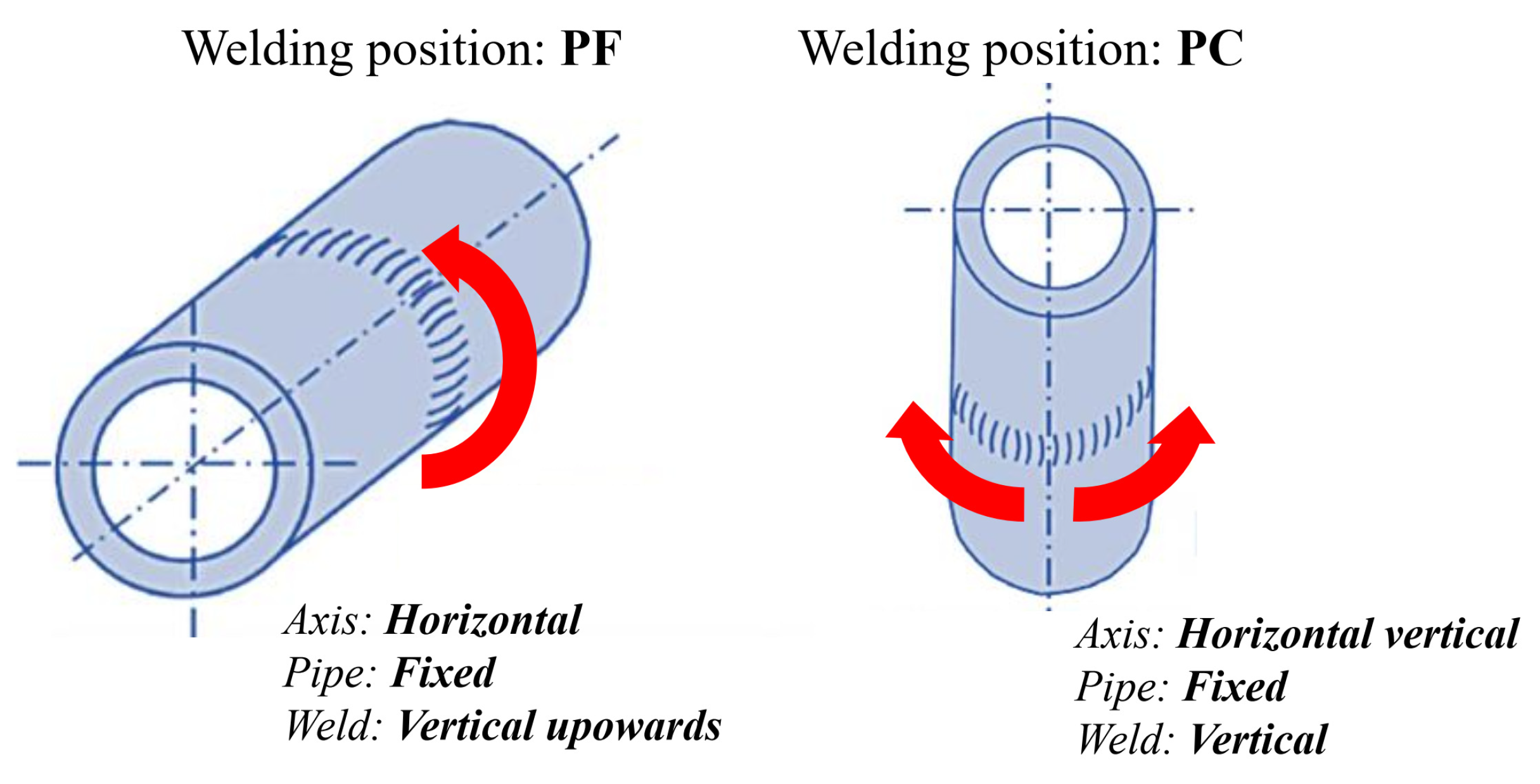
| Pipe Designation | Welding Position | Welding Process | Thickness [mm] | Outside Diameter [mm] | Joint Type | Remark |
|---|---|---|---|---|---|---|
| PF1 | PF | GTAW/SMAW | 70 | 280 | BW-U | Welding |
| PC2 | PC | GTAW/SMAW | 70 | 280 | BW-U | Welding |
| PF3 | PF | GTAW/SMAW | 70 | 280 | BW-U | Repair welding |
| Filler Material/Element | C | Mn | Mo | Si | Cr | Ni | W | Nb | V | N | Fe |
|---|---|---|---|---|---|---|---|---|---|---|---|
| W Z CrMoWVNb 9 0.5 1.5 | 0.1 | 0.5 | 0.4 | 0.25 | 8.5 | 0.5 | 1.6 | 0.06 | 0.2 | 0.04 | bal. |
| E Z CrMoWVNb 9 0.5 2 B 4 2 H5 | 0.1 | 0.7 | 0.55 | 0.3 | 8.6 | 0.7 | 0.06 | 0.04 | 0.2 | 0.04 | bal. |
| Filler Material | Re [MPa] | Rm [MPa] | A (L0 = 5d0) [%] | Impact Fracture [J] |
|---|---|---|---|---|
| W Z CrMoWVNb 9 0.5 1.5 | 560 | 720 | >15 | >41 |
| E Z CrMoWVNb 9 0.5 2 B 4 2 H5 | 600 | 740 | 20 | >55 |
| Pass | Process | Filler Metal Diameter [mm] | Current [A] | Voltage [V] | Type of Current/ Polarity | Heat Input [kJ/mm] |
|---|---|---|---|---|---|---|
| Root 1 | GTAW | 2.4 | 95–105 | 13–15 | DC- | ~0.84 |
| Fill 2–3 | GTAW | 2.4 | 125–135 | 13–15 | DC- | ~1.05 |
| 4–5 | GTAW | 2.4 | 135–145 | 13–15 | DC- | ~1.17 |
| 6–8 | SMAW | 2.5 | 70–80 | 21–23 | DC+ | ~1.3 |
| 9–11 | SMAW | 2.5 | 80–95 | 21–23 | DC+ | ~1.4 |
| 12–14 | SMAW | 2.5 | 80–95 | 21–23 | DC+ | ~1.4 |
| 15–17 | SMAW | 3.2 | 100–105 | 21–23 | DC+ | ~1.5 |
| 18–20 | SMAW | 3.2 | 100–110 | 21–23 | DC+ | ~1.5 |
| 21–23 | SMAW | 3.2 | 110–120 | 21–23 | DC+ | ~1.5 |
| 24–27 | SMAW | 3.2 | 105–125 | 21–23 | DC+ | ~1.5 |
| 28–31 | SMAW | 3.2 | 110–125 | 21–23 | DC+ | ~1.5 |
| 32–35 | SMAW | 3.2 | 115–125 | 21–23 | DC+ | ~1.55 |
| 36–39 | SMAW | 3.2 | 115–125 | 21–23 | DC+ | ~1.5 |
| 40–43 | SMAW | 4.0 | 120–135 | 21–23 | DC+ | ~1.6 |
| 44–48 | SMAW | 4.0 | 120–135 | 21–23 | DC+ | ~1.6 |
| 49–53 | SMAW | 4.0 | 120–135 | 21–23 | DC+ | ~1.5 |
| 54–58 | SMAW | 4.0 | 115–135 | 21–23 | DC+ | ~1.6 |
| 59–62 | SMAW | 3.2 | 115–135 | 21–23 | DC+ | ~1.6 |
| 63–67 | SMAW | 4.0 | 130–135 | 21–23 | DC+ | ~1.6 |
| 68–72 | SMAW | 3.2 | 110–115 | 21–23 | DC+ | ~1.5 |
| 73–77 | SMAW | 3.2 | 110–115 | 21–23 | DC+ | ~1.4 |
| 78–82 | SMAW | 3.2 | 110–115 | 21–23 | DC+ | ~1.4 |
| 83–87 | SMAW | 3.2 | 110–115 | 21–23 | DC+ | ~1.4 |
| 88–92 | SMAW | 2.5 | 80 | 21–23 | DC+ | ~1.4 |
| Cover 93–98 | SMAW | 2.5 | 80–85 | 21–23 | DC+ | ~1.3 |
| Pass | Process | Filler Metal Diameter [mm] | Current [A] | Voltage [V] | Type of Current/Polarity | Heat Input [kJ/mm] |
|---|---|---|---|---|---|---|
| Root 1 | GTAW | 2.4 | 100–110 | 13–15 | DC- | ~0.9 |
| Fill 2–4 | GTAW | 2.4 | 140–145 | 13–15 | DC- | ~1.1 |
| 5–7 | GTAW | 2.4 | 140–145 | 13–15 | DC- | ~1.1 |
| 8–11 | SMAW | 2.5 | 80–90 | 21–23 | DC+ | ~1.3 |
| 12–15 | SMAW | 2.5 | 85–95 | 21–23 | DC+ | ~1.3 |
| 16–19 | SMAW | 2.5 | 90–100 | 21–23 | DC+ | ~1.35 |
| 20–23 | SMAW | 3.2 | 110–120 | 21–23 | DC+ | ~1.5 |
| 24–27 | SMAW | 3.2 | 115–125 | 21–23 | DC+ | ~1.5 |
| 28–31 | SMAW | 3.2 | 115–125 | 21–23 | DC+ | ~1.5 |
| 32–35 | SMAW | 3.2 | 115–125 | 21–23 | DC+ | ~1.5 |
| 36–39 | SMAW | 3.2 | 120–130 | 21–23 | DC+ | ~1.6 |
| 40–43 | SMAW | 3.2 | 120–130 | 21–23 | DC+ | ~1.6 |
| 44–47 | SMAW | 3.2 | 120–130 | 21–23 | DC+ | ~1.6 |
| 48–51 | SMAW | 4.0 | 140–150 | 21–23 | DC+ | ~1.7 |
| 52–56 | SMAW | 4.0 | 140–150 | 21–23 | DC+ | ~1.6 |
| 57–61 | SMAW | 4.0 | 140–150 | 21–23 | DC+ | ~1.7 |
| 62–66 | SMAW | 4.0 | 140–150 | 21–23 | DC+ | ~1.6 |
| 67–71 | SMAW | 4.0 | 140–150 | 21–23 | DC+ | ~1.7 |
| 72–76 | SMAW | 4.0 | 130–135 | 21–23 | DC+ | ~1.6 |
| 77–82 | SMAW | 3.2 | 120–130 | 21–23 | DC+ | ~1.4 |
| 83–88 | SMAW | 3.2 | 125 | 21–23 | DC+ | ~1.4 |
| 89–94 | SMAW | 3.2 | 125 | 21–23 | DC+ | ~1.5 |
| 95–100 | SMAW | 4.0 | 140–150 | 21–23 | DC+ | ~1.6 |
| Cover 101–109 | SMAW | 2.5 | 80–90 | 21–23 | DC+ | ~1.3 |
| Pass | Process | Filler Metal Diameter [mm] | Current [A] | Voltage [V] | Type of Current/Polarity | Heat Input [kJ/mm] |
|---|---|---|---|---|---|---|
| Root 1 | GTAW | 2.4 | 85–95 | 13–15 | DC- | ~0.6 |
| Fill 2–4 | GTAW | 2.4 | 100–110 | 13–15 | DC- | ~0.9 |
| 5–7 | GTAW | 2.4 | 115–125 | 13–15 | DC- | ~1 |
| 8–10 | GTAW | 2.4 | 125–135 | 13–15 | DC- | ~1.1 |
| 11–13 | GTAW | 2.4 | 140–150 | 13–15 | DC- | ~1.1 |
| 14–17 | GTAW | 2.4 | 145–155 | 13–15 | DC- | ~1.15 |
| 18–21 | GTAW | 2.4 | 145–155 | 13–15 | DC- | ~1.1 |
| 22–25 | GTAW | 2.4 | 145–155 | 13–15 | DC- | ~1.15 |
| 26–29 | GTAW | 2.4 | 190–200 | 13–15 | DC- | ~1.4 |
| 30–33 | GTAW | 2.4 | 190–200 | 13–15 | DC- | ~1.4 |
| 34–36 | SMAW | 3.2 | 120–130 | 21–23 | DC+ | ~1.6 |
| 37–39 | SMAW | 3.2 | 120–130 | 21–23 | DC+ | ~1.6 |
| 40–42 | SMAW | 3.2 | 120–130 | 21–23 | DC+ | ~1.5 |
| 43–46 | SMAW | 3.2 | 120–130 | 21–23 | DC+ | ~1.5 |
| 47–50 | SMAW | 3.2 | 120–130 | 21–23 | DC+ | ~1.5 |
| 51–54 | SMAW | 3.2 | 120–130 | 21–23 | DC+ | ~1.5 |
| 55–58 | SMAW | 3.2 | 120–130 | 21–23 | DC+ | ~1.6 |
| 59–62 | SMAW | 3.2 | 120–130 | 21–23 | DC+ | ~1.6 |
| 63–66 | SMAW | 3.2 | 120–130 | 21–23 | DC+ | ~1.5 |
| 67–70 | SMAW | 3.2 | 120–130 | 21–23 | DC+ | ~1.5 |
| 71–75 | SMAW | 3.2 | 120–130 | 21–23 | DC+ | ~1.5 |
| 76–80 | SMAW | 3.2 | 120–130 | 21–23 | DC+ | ~1.6 |
| 81–85 | SMAW | 3.2 | 120–130 | 21–23 | DC+ | ~1.6 |
| 86–90 | SMAW | 3.2 | 120–130 | 21–23 | DC+ | ~1.5 |
| Cover 91–96 | SMAW | 2.5 | 80–90 | 21–23 | DC+ | ~1.1 |
| Specimen Label | Rp0.2 [MPa] | Rm [MPa] | A [%] | Z [%] | Fracture Location |
|---|---|---|---|---|---|
| PF1-1 | 498 | 682 | 16 | 69 | parent material |
| PF1-2 | 474 | 678 | 19 | 70 | parent material |
| PC2-1 | 498 | 684 | 17 | 68 | parent material |
| PC2-2 | 474 | 678 | 18 | 71 | parent material |
| PF3-1 | 464 | 637 | 17 | 73 | parent material |
| PF3-2 | 472 | 632 | 17 | 73 | parent material |
Disclaimer/Publisher’s Note: The statements, opinions and data contained in all publications are solely those of the individual author(s) and contributor(s) and not of MDPI and/or the editor(s). MDPI and/or the editor(s) disclaim responsibility for any injury to people or property resulting from any ideas, methods, instructions or products referred to in the content. |
© 2025 by the authors. Licensee MDPI, Basel, Switzerland. This article is an open access article distributed under the terms and conditions of the Creative Commons Attribution (CC BY) license (https://creativecommons.org/licenses/by/4.0/).
Share and Cite
Vučetić, F.; Đorđević, B.; Radu, D.; Dikić, S.; Jeremić, L.; Milovanović, N.; Sedmak, A. Mechanical Properties of Repaired Welded Pipe Joints Made of Heat-Resistant Steel P92. Materials 2025, 18, 2908. https://doi.org/10.3390/ma18122908
Vučetić F, Đorđević B, Radu D, Dikić S, Jeremić L, Milovanović N, Sedmak A. Mechanical Properties of Repaired Welded Pipe Joints Made of Heat-Resistant Steel P92. Materials. 2025; 18(12):2908. https://doi.org/10.3390/ma18122908
Chicago/Turabian StyleVučetić, Filip, Branislav Đorđević, Dorin Radu, Stefan Dikić, Lazar Jeremić, Nikola Milovanović, and Aleksandar Sedmak. 2025. "Mechanical Properties of Repaired Welded Pipe Joints Made of Heat-Resistant Steel P92" Materials 18, no. 12: 2908. https://doi.org/10.3390/ma18122908
APA StyleVučetić, F., Đorđević, B., Radu, D., Dikić, S., Jeremić, L., Milovanović, N., & Sedmak, A. (2025). Mechanical Properties of Repaired Welded Pipe Joints Made of Heat-Resistant Steel P92. Materials, 18(12), 2908. https://doi.org/10.3390/ma18122908