Article

A Finite Element Analysis of a New Dental Implant Design: The Influence of the Diameter, Length, and Material of an Implant on Its Biomechanical Behavior

by
Pedro González-Mederos
1,
Jennifer Rodríguez-Guerra
1,
Jesús E. González
1,2,*,
Alberto Picardo
3 and
Yadir Torres
4,*
1
Departamento de Biomateriales Cerámicos y Metálicos, Centro de Biomateriales, Universidad de La Habana, Ave. Universidad s/n Entre G y Ronda, Vedado, La Habana 10400, Cuba
2
Grupo de Biomecánica, Facultad de Mecánica, Universidad Tecnológica de la Habana “José Antonio Echeverría”, Dirección Calle 114, # 11901, e/Ciclovía y Rotonda, Marianao, Cujae, La Habana 19390, Cuba
3
Departamento de Ingeniería del Diseño, Escuela Politécnica Superior de Sevilla, Universidad de Sevilla, Calle Virgen de África, 7, 41011 Sevilla, Spain
4
Ingeniería y Ciencia de los Materiales y del Transporte, Escuela Politécnica Superior de Sevilla, Universidad de Sevilla, Calle Virgen de África, 7, 41011 Sevilla, Spain
*
Authors to whom correspondence should be addressed.
Materials 2025, 18(12), 2692; https://doi.org/10.3390/ma18122692 (registering DOI)
Submission received: 2 May 2025 / Revised: 31 May 2025 / Accepted: 3 June 2025 / Published: 7 June 2025

Abstract

:
It is widely recognized that excessive stress and/or strain can lead to peri-implant bone atrophy; therefore, the clinical success of dental implants is intrinsically related to their biomechanical behavior. This study evaluates the influence of the diameter, length, and material [Ti6Al4V (α+β Ti) and Ti35Nb7Zr5Ta (β-Ti)] of a novel cylindrical dental implant on stress and strain levels within maxillary bone of type II quality. The implant design aims to ensure an appropriate distribution of stresses and strains within the peri-implant bone structures (cortical and trabecular bones) while also facilitating surgical machining by requiring a simple, linear, and less expensive bone incision. This approach minimizes the risk of thermal necrosis, a common complication in osteotomies for conical implants that can lead to peri-implant bone loss. Using finite element analysis, stress and strain patterns were evaluated in the maxillary second premolar region under static delayed loading. The results reveal that the cortical bone strains remained below the critical threshold (0.003) to prevent resorption. In the trabecular bone, only larger diameter/length configurations satisfied the previous strain criterion. In all simulations, trabecular bone stress remained below 3 MPa, whereas cortical bone stress peaked at 78 MPa. Notably, the implant model with the largest diameter/length minimized stress and strain concentrations in type II bone when compared to smaller designs, thereby demonstrating its biomechanical advantage.

Graphical Abstract

1. Introduction

In recent decades, substantial progress has been achieved in prosthetic dentistry, leading to notable improvements in both dental implant technology and surgical techniques. The primary focus of these advances has been to ensure predictable clinical outcomes while simultaneously enhancing functional performance and esthetic results in patients with complete or partial edentulism [1]. The efficacy of prosthetic rehabilitation depends on multiple variables that can influence the biomechanical interaction between the implant and the osseous tissue [2,3]. These factors encompass the exact positioning of the implant, the inherent mechanical and structural properties of the bone tissue, the mechanical and geometric features of the implant itself, and the intensity and type of load transmitted from the implant to the surrounding bone [4,5,6]. Additionally, it is necessary to consider patient-specific factors such as smoking habits and bacterial environment [7,8,9].
The success of dental implant treatment depends, among other factors, on the efficient transfer of occlusal loads at the bone–implant interface [10]. Multiple elements, including the loading regimen, implant surface topography, available bone volume, as well as the material properties and design characteristics of the implant, influence this load transfer [11]. An optimal design can mitigate stress and strain concentrations while improving their distribution patterns, thus improving the probability of long-term implant survival [12]. Stress and strain distributions in the peri-implant bone are directly affected by the nature of the applied load [13]. Excessive mechanical loading (overload conditions) may initiate bone micro-fractures, potentially leading to implant loosening or catastrophic failure. Furthermore, overload situations can cause accelerated bone resorption in the peri-implant region and reduce trabecular bone density [14]. Regarding implant materials, they must demonstrate essential characteristics including biocompatibility, structural durability, and superior resistance to corrosion, wear, and mechanical fracture [15].
The selection of an appropriate dental implant necessitates a comprehensive evaluation of the residual alveolar bone, incorporating an assessment of the vertical bone height and mesiodistal dimensions of the edentulous space, to achieve optimal biomechanical performance and esthetic results [16,17]. Clinical guidelines recommend maintaining a minimum distance of 1.25 mm between an implant and adjacent natural teeth, providing adequate space to support bone and periodontal ligament tissue while ensuring sufficient vascular supply for successful osseointegration. Additionally, a minimum circumferential bone thickness of 0.5 mm surrounding the implant must be preserved to ensure the long-term clinical stability and success of prosthetic rehabilitation [18,19]. Post-extraction bone resorption in the maxilla leads to reduced residual bone height, particularly in the posterior region, where proximity to the maxillary sinus complicates the placement of standard-length implants [20]. Although bone grafting and sinus lift procedures are well-established treatment options, they are associated with increased morbidity and a prolonged duration of treatment. Short implants provide a minimally invasive solution without compromising primary stability as larger diameters and optimized implant body geometry can compensate for reduced length, thereby enhancing initial retention in low-density maxillary bone [21].
It is important to note that bone tissue responds to alterations in the loading conditions to which it is subjected. This phenomenon, known as bone remodeling, involves the ability of the bone to adapt and modify itself to achieve a balance between strength and resistance [22,23,24]. However, overload conditions can lead to bone fracture, fatigue failure, and detrimental consequences, including marginal bone loss or even osseointegration failure [25,26]. Peri-implant bone resorption can be triggered by various factors, such as surgical trauma, bacterial infections, and states of overload or underload, but to a lesser extent [6,27,28]. Overload in the peri-implant bone can occur due to deficiencies in the load transfer mechanisms, such as malocclusion, incorrect use of the implant, incorrect design of the prosthetic crown and/or implant, and improper placement of the implant. Consequently, this can result in high stress concentrations and/or strains at the bone–implant interface and, ultimately, bone resorption [29,30].
In essence, biomechanical load transfer at the bone–implant interface constitutes a critical determinant of dental implant success. Optimal implant design, including its geometry, diameter, length, and three-dimensional positioning within the maxilla, plays a pivotal role in governing the occlusal load distribution and the subsequent bone adaptive response [31,32,33]. A design that promotes a balanced load distribution and minimizes stress concentrations can help prevent bone resorption and improve the durability and clinical effectiveness of implant rehabilitations [34,35,36].
The use of finite element analysis (FEA) in prosthetic dentistry has become a predominant quantitative method to investigate the biomechanical behavior of dental implants in various clinical scenarios [37,38]. This technique enables the prediction of stress and strain distributions in peri-implant regions while considering multiple variables, including implant and prosthesis design, load magnitude and direction, bone mechanical properties, and other case-specific conditions [39]. The principal advantage of the FEA method lies in its ability to simulate the complexity of real clinical situations. Enabling the modeling of complex geometries and materials and the interactions between various components of the biomechanical system facilitates a more accurate understanding of the mechanical behavior within bone [40,41]. Consequently, this approach allows for the identification of potential overloaded regions or underloaded zones that may trigger bone resorption or implant failure [42,43,44]. However, it must be recognized that FEA studies are not exempt from certain assumptions and limitations. These encompass the selection of material properties, boundary condition definitions, interface characterizations between components, and the general modeling methodology [35,45]. The validity of FEA-derived results depends on the rigor of these assumptions and considerations and on the precise experimental validation of the models. Furthermore, these results are used to optimize the design of dental implants by incorporating modifications in geometry and dimensions [46,47]. In summary, using FEA for examining dental implant biomechanics offers significant benefits by enabling comprehensive simulation and analysis of complex bone–implant system interactions [48]. Nevertheless, the results must be interpreted cautiously as they remain subject to the inherent assumptions and limitations of the modeling approach, as previously outlined [49].
Ti6Al4V (α+β Ti) alloys are widely used in implant applications. However, their high elastic modulus (~110 GPa) and limited bioactivity can lead to stress concentrations at the bone–implant interface and contribute to peri-implant bone resorption. In contrast, β-phase titanium alloys such as Ti35Nb7Zr5Ta (β-Ti) present significant advantages, including a lower elastic modulus (~55 GPa), more similar to cortical bone (~10–30 GPa), along with improved corrosion resistance and biocompatibility [50]. Recent computational and in vivo studies have shown that β-Ti alloys promote more favorable strain distributions, reducing stress shielding and improving load transfer at the bone–implant interface. However, comprehensive evaluations of their micromechanical behavior remain limited [51].
Although widely used, conical implants exhibit critical biomechanical and surgical limitations: (1) their design induces stress concentration at the apex, increasing the risk of microfractures in high-density bone (types I and II); (2) complex bone preparation (tapered surgical drilling) may cause overheating and necrosis, leading to cortical bone loss, and (3) reduced initial bone-to-implant contact at the apical portion compromises early osseointegration [52]. Cylindrical implants offer key advantages as a potential solution: (a) uniform load distribution by eliminating localized stress points; (b) simplified (straight) and less invasive osteotomy, preserving bone integrity and minimizing thermal risks; and (c) greater initial bone contact area, enhancing osseointegration in high-density bone (type II) [53]. The standardized drilling protocol for cylindrical implants reduces surgical time, instrument costs, and thermal complications compared to conical systems, offering significant economic advantages in high-density bone [54]. This perspective challenges the approach paradigm, suggesting that cylindrical designs optimize both biomechanical performance and cost-efficiency in specific bone phenotypes, with direct implications for clinical planning and long-term implant longevity. A novel single-component cylindrical dental implant was designed, offering significant advantages: it eliminates the microgap and connection interfaces present in two-piece systems, which are prone to bacterial colonization, screw loosening, and galvanic corrosion. In addition, it improves biomechanical stability by distributing occlusal forces uniformly through a single-unit structure, reducing stress concentration at prosthetic junctions, and it simplifies clinical workflows by avoiding abutment seating inaccuracies, thereby improving primary stability, a key requirement for early functional loading.
The objective of this study is to assess the impact of the diameter, length, and material (Ti6Al4V (α+β Ti) and Ti35Nb7Zr5Ta (β-Ti)) on the biomechanical behavior of a new cylindrical dental implant model. Specifically, its influence was evaluated on the maximum levels of von Mises equivalent stresses and von Mises strains in the peri-implant bone (cortical and trabecular bone) of the second premolar region of the maxillary.

2. Materials and Methods

2.1. Dental Implant Models

The geometry of a single-component dental implant model used in previous studies was modified to reduce production costs and simplify its anchoring process in the maxilla [55,56]. Specifically, the taper of the referenced design was significantly reduced. Based on these modifications, six variants of the new single-component dental implant model (Figure 1) were obtained in the Autodesk Inventor 2020 software (Autodesk Inc., San Francisco, CA, USA), differentiated by their length and diameter values (Table 1). The implants had a thread that extended throughout the length of the implant body to which a second thread was added in the proximal area (close to its neck), both with a rectangular profile. In the implant body, two helical grooves were extended to enable self-tapping into the maxillary bone. Furthermore, to determine the influence of its dimensions on its biomechanical behavior, the length of the threaded portion (implant body, L) and the diameter of its neck (D) were varied (Table 1).

2.2. The Assembly of the Crown Dental Implant System

To place the implants, the maxilla model obtained by Pérez from medical image processing was used [57]. The maxilla model, including adjacent teeth to the premolar, was modeled as a single solid body. Cuts were made to the model, and a geometry smoothing process was carried out at the limits of the premolar area to facilitate processing in the simulation software.
In Autodesk Inventor software, the six dental implant models were assembled with a ceramic crown, corresponding to the second premolar. Then, threaded holes were designed in the jaw according to the dimensions of each dental implant, and the crown dental implant systems were placed in these to form four assemblies. Subsequently, the assemblies were exported in .sat format to the Abaqus/CAE simulation software (6.13).

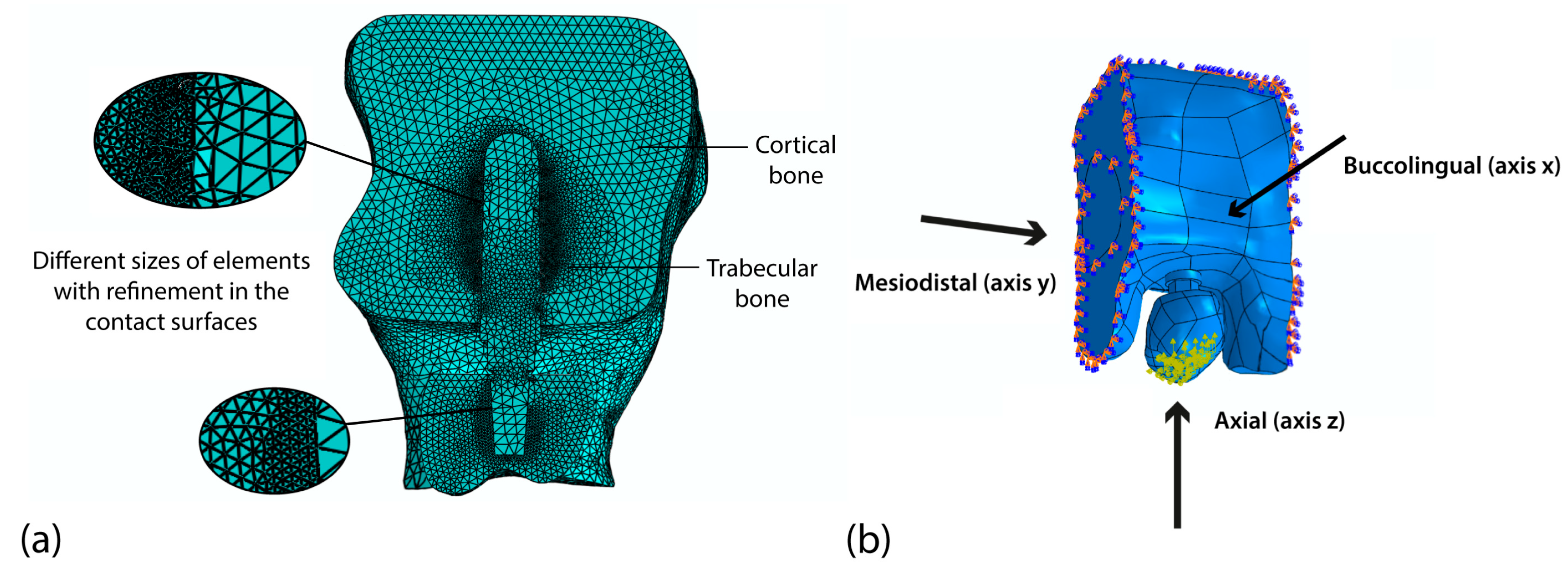
2.3. Analysis Using the Finite Element Method

The von Mises equivalent stress (VMES) and von Mises strain values (VMS) in the cortical and trabecular bones were obtained by the FEA using the Abaqus/CAE simulation software (Simulia Corp, Vélizy-Villacoublay, France, version 6.13). The system components were exported to Abaqus as separate parts, where material definitions were established and the mechanical properties specified in Table 2 were assigned. Cortical and trabecular bone (type II quality) were modeled with anisotropic material properties, while isotropic properties were assigned to the implant and crown. Additionally, all materials were treated as homogeneous volumes exhibiting linear elastic behavior.
Interactions were established between the contact surfaces of the system components, considering the physical unions that exist between these elements, with the use of a Tie type restriction, which implies that the condition of the defined surfaces is a single one. A global mesh (Figure 2a), with tetrahedral elements with an approximate size of 0.7 mm was implemented, whereas a locally refined mesh with a size of 0.2 mm was used on contact surfaces. The number of nodes and system elements in all simulations depends on the size of the mesh and varies according to changes in implant geometry. The system with the smallest implant dimensions (3.7 and 8 mm) has the lowest number of elements and nodes (1,826,206 elements and 339,497 nodes), whereas the system with the largest implant dimensions (4.0 and 12 mm) exhibits the highest values for these parameters (1,888,761 elements and 349,037 nodes). To guarantee the accuracy of the stress and strain values obtained, a convergence test was carried out, maintaining the load and boundary conditions. In this test, a tetrahedral mesh with a refinement of 0.16 mm was used for the contact surfaces, and a refinement of 0.6 mm was used in the global mesh. The result was an error of less than 2%.
A delayed loading condition was simulated, considering the implant as fully osseointegrated. Multidirectional occlusal loads were applied simultaneously along three anatomical axes: axial (117 N), bucco-lingual (21.58 N), and mesio-distal (29.48 N). Considering that the implant was anchored at the second premolar site, the applied loads slightly increased compared to those used by Himmlová et al. for a first premolar [62]. The occlusal surface was modeled as the entire crown surface of the premolar, with loads applied across a set of 30 nodes distributed on most of its geometry to ensure physiologically representative force application (Figure 2b). This approach allowed for balanced load transmission while accounting for anatomical variability (e.g., cusp inclination and marginal ridges) to ensure proper load distribution. By considering the entire occlusal surface rather than isolated contact points, the model more accurately replicates in vivo loading conditions, where mastication forces are distributed across the crown. Boundary conditions were implemented by fully constraining the bone model, restricting all degrees of freedom to simulate embedded conditions.

2.4. Experimental Design and Statistical Analysis

This study evaluated the influence of two key parameters on the stress and strain levels in peri-implant cortical and trabecular bone. Three different threaded portion lengths (Ls) and two implant neck diameters (Ds) were analyzed using the finite element method simulations. Consequently, the experimental design consisted of six test configurations, as detailed in Table 1. The diameter and length parameter values used in the simulated dental implant models fall within the ranges used in implants produced by various commercial manufacturers. However, for the length values, experimental runs A and D are considered short implants. Six experimental runs were performed using the Ti6Al4V alloy, supplemented by two additional runs (smallest and largest implant designs A and F) employing β-titanium Ti35Nb7Zr5Ta.
All stress and strain values were extracted from the experimental runs in the trabecular and cortical bones, and the 300 most loaded nodes generated by each experimental run were selected to evaluate the biomechanics of the dental implant. The selected nodes were compiled in Microsoft Office Excel; subsequently, the data sheets were exported to StatGraphics Centurion XIX software (v.19) (Statpoint Technologies Inc., Warrenton, VA, USA). In this software, box-and-whisker analysis was used to determine the VMES and aberrant VMS values. The values were subjected to a normality test (Kolmogorov–Smirnov test) and subsequently analyzed using an analysis of variance (ANOVA). Additionally, a Kruskal–Wallis test was used to identify differences between groups, and a value of p < 0.05 considered statistically significant.

3. Results and Discussion

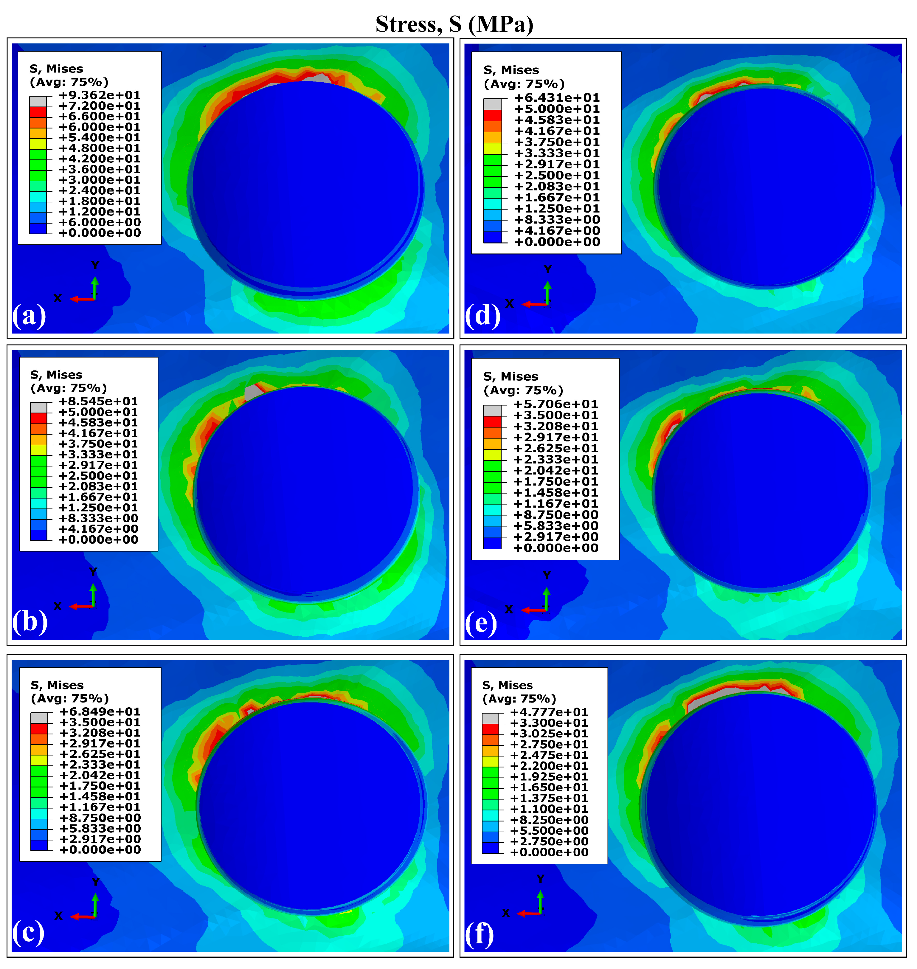
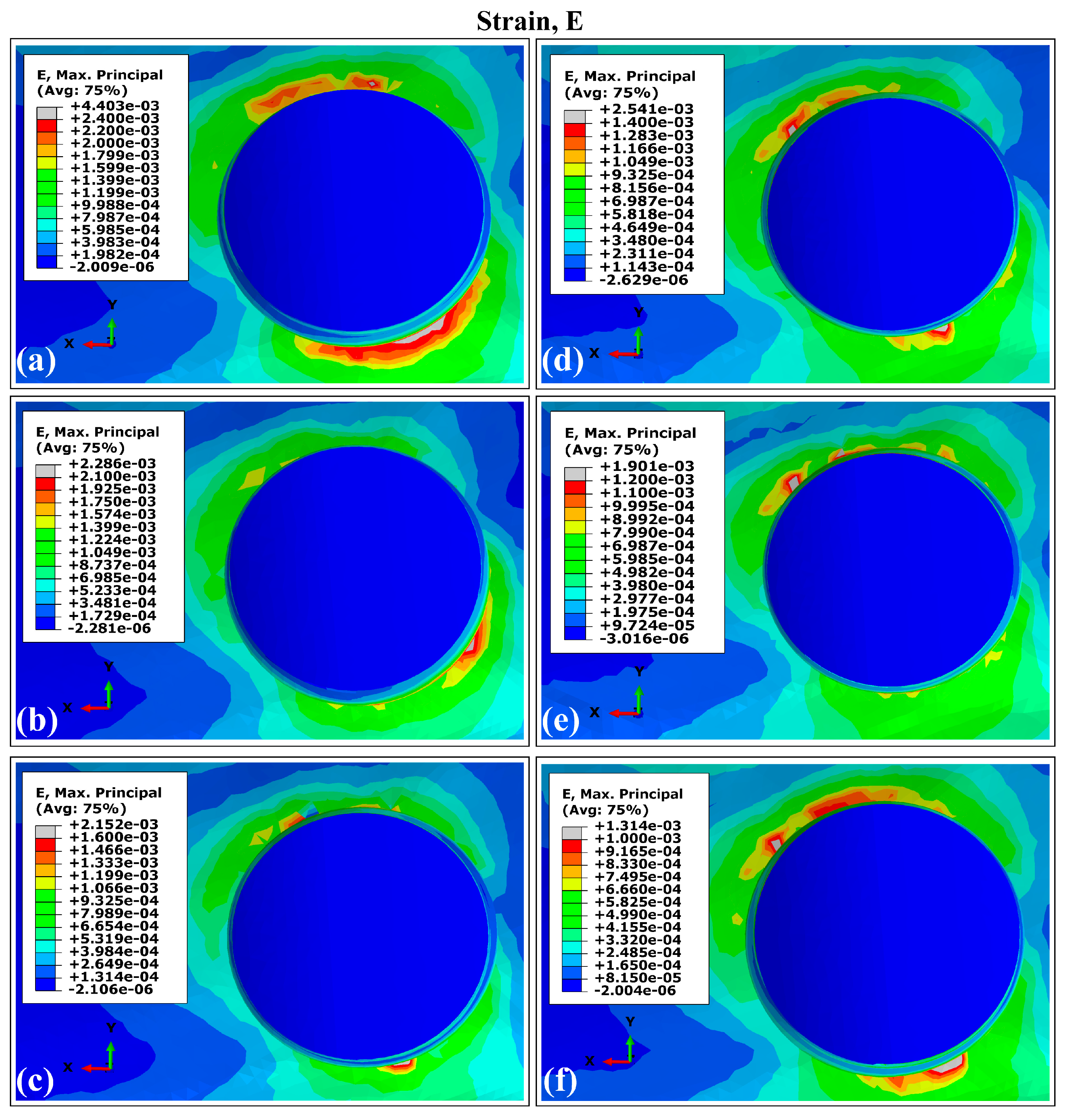
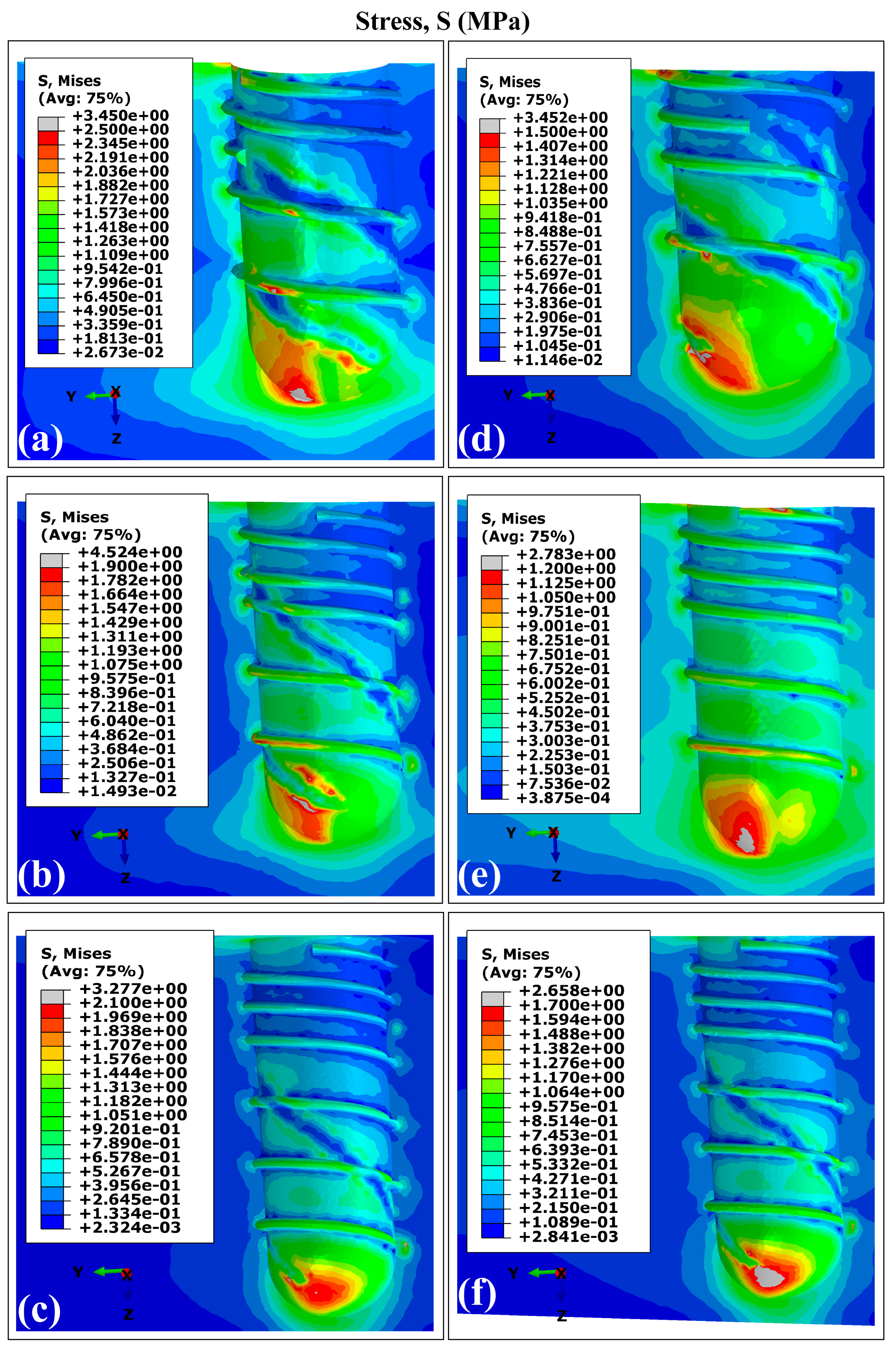
3.1. Stress and Strain Distribution Patterns in Cortical Bone Using Ti6Al4V (α+β Ti)

The VMES distributions and VMS distributions generated in cortical bone by the experimental runs are presented in Figure 3 and Figure 4. All evaluated models produced similar distribution patterns for both parameters, characterized by peak concentrations in peri-implant bone, particularly in the maxillary superior region adjacent to the implant necks. This observed behavior aligns with the findings reported in previous studies involving a finite element analysis of dental implants [40,63,64]. The maximum values for both mechanical parameters were consistently located around the distal aspect, while the minimum values occurred predominantly in areas interfacing with trabecular bone. Regarding the superior maxillary region, the peak values of von Mises equivalent stresses (MVMES) and strains (MVMS) demonstrated dimensional dependence, which varied according to implant geometric parameters.

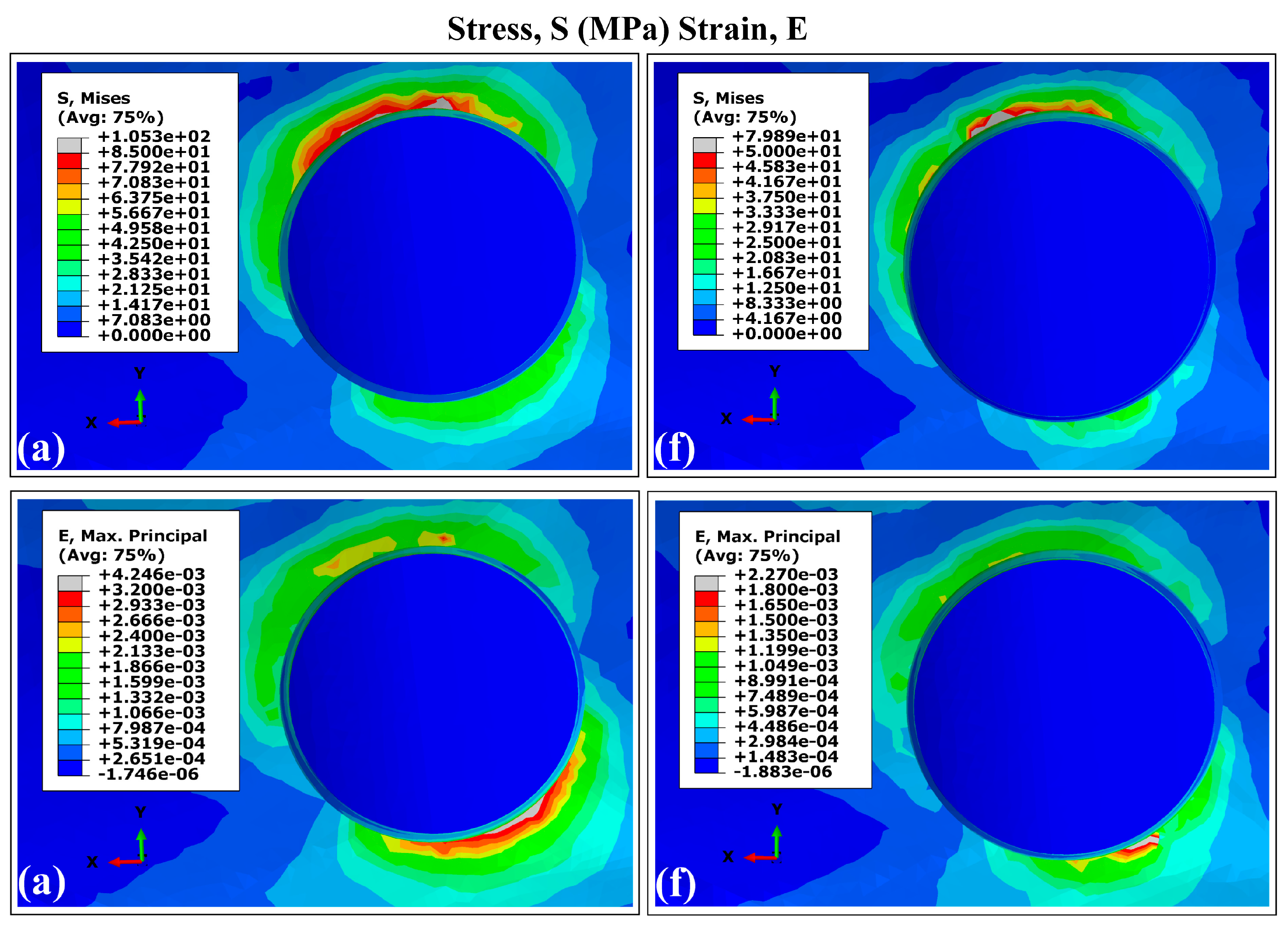
Stress and Strain Distribution Patterns in Cortical Bone Using Ti35Nb7Zr5Ta (β-Ti)

Figure 5 shows the von Mises stress and strain distributions in cortical bone for implants with smaller and larger dimensions (runs A and F). Both implant designs produced similar stress and strain patterns under the same conditions, showing similar results to those generated by Ti6Al4V dental implants and presenting the highest values concentrated in the peri-implant bone, around the implant neck in the superior maxilla. These results are consistent with previous finite element studies of dental implants [40,59,60]. The maximum values of VMES and VMS were observed at the distal site, while the lowest values were found in regions adjacent to trabecular bone. In the superior maxillary area, the peak magnitudes of VMES (MVMES) and VMS (MVMS) exhibited dimensional dependence, correlating with variations in implant geometry.

3.2. Distribution Patterns of Stresses and Strains in Trabecular Bone Using Ti6Al4V (α+β Ti)

Figure 6 and Figure 7 present the VMES and VMS distributions in the trabecular bone for all experimental configurations. The peak values for both parameters were concentrated primarily in two regions: (1) in the interface with the apical zone of the implant, and (2) for strain distributions specifically, the threaded implant surface at the distal site. This mechanical behavior stems from the geometry of the thread acting as a stress concentration feature due to its complex three-dimensional morphology.
The implant models produced comparable stress and strain distribution patterns in the trabecular bone, with reduced values for both mechanical parameters observed in regions interfacing with the double-threaded portion. However, variants C and F (which feature longer stem lengths) demonstrated more uniform distribution patterns. Specifically, these configurations showed diminished differences between VMES and VMS values when comparing distal versus mesial sites, as well as between peri-implant bone regions adjacent to apical versus proximal implant sections.

Distribution Patterns of Stresses and Strains in Trabecular Bone Using Ti35Nb7Zr5Ta (β-Ti)

The FEA of the VMES and VMS distributions in trabecular bone for the largest and smallest implant dimensions fabricated using Ti35Nb7Zr5Ta (β-Ti) are shown in Figure 8. Consistent with the simulations using the Ti6Al4V alloy, the implant with the largest length and diameter dimensions (F) exhibited a significant reduction in the peak VMES and VMS values in the trabecular bone compared to those generated by variant A. Higher VMES values were found at the bone–implant interface near the apical region, while peak VMS values were concentrated around the distal threads, likely due to the abrupt changes in geometry. These results highlight the combined mechanical effect of implant features: the apical engagement supports primary stability, while the thread design affects how strain is distributed locally. Compared to Ti6Al4V, the β-Ti alloy led to a more even distribution of stress along the implant, especially in the apical region, suggesting improved biomechanical performance.

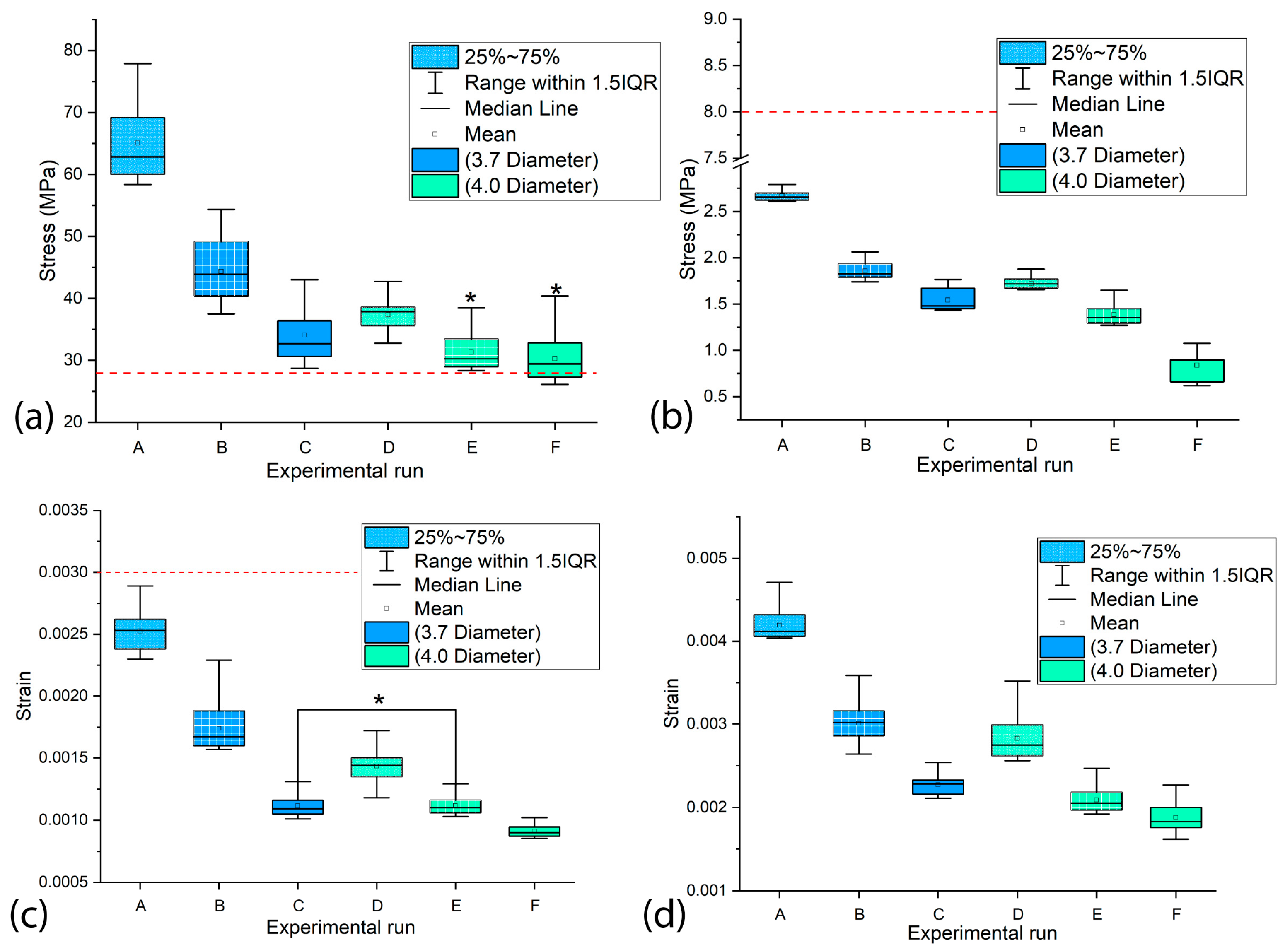
3.3. The Influence of the Diameter and Length of the Dental Implants on the Values of MVMES and MVMS in the Peri-Implant Bone

Long-term peri-implant bone quality has been shown to correlate directly with the stress and strain values induced in bone tissue [14,55,65]. Excessive and insufficient mechanical stimulation can adversely affect implant biomechanical performance [66,67]. Typically, the stress peak occurs primarily in peri-implant cortical bone. The underload zones appear in the trabecular bone regions. This stress reduction phenomenon results from the modulus mismatch between implant materials (generally exhibiting high Young’s modulus) and surrounding bone tissue [68,69,70].
In the peri-implant cortical bone, areas with stress values that constitute overloads were observed. However, stress and strain values prevailed within the range that favors bone remodeling and in which bone tissue density is maintained. It is known that overloads can rapidly generate both dimensional losses in the jaws and a decrease in the density of the peri-implant bone [65]. On the other hand, the lower stress values observed in the peri-implant trabecular bone were within the levels considered as underload for quality II bone tissue; this behavior must be related to the stress shielding effect. In the case of the strains, values were lower than 0.003, although in some areas, their levels were close to the recommended lower limit, which could generate a loss of peri-implant bone density [71]. In the cortical and trabecular bones, stress and strain distributions with underload areas were obtained in the peri-implant bone (Figure 3, Figure 4, Figure 6 and Figure 7). Although slower and more moderate than overload, it can affect bone density because insufficient mechanical stimuli sustained over time cause bone tissue to be unable to perform the bone remodeling process and therefore maintain its density [30].
In cortical bone, stress levels were obtained within a range of 30–78 MPa and strains between 0.0010 and 0.0027. These findings partially align with previous studies that analyzed the effect of implant geometry and dimensions on stress levels. Baggi et al. reported, for Nobel Biocare designs, higher stresses (40–90 MPa) in conical implants, suggesting that cylindrical designs, such as the one used in our study, can promote a more favorable load transmission [72]. Meanwhile, Ding et al. observed that increasing implant diameter led to a reduction in bone strains, which is consistent with our findings, although their study evaluated conical implants [73]. In contrast, Muangsisied et al. found that implant length had a limited impact on cortical stresses, whereas our study detected significant variations when modifying this parameter [74]. These discrepancies could be attributed to differences in geometric configurations (cylindrical versus conical) and loading conditions, reinforcing the importance of optimizing implant design based on bone characteristics.
The results obtained in trabecular bone (stresses: 1–3 MPa; strains: 0.002–0.0045) demonstrate certain advantages compared to the previous literature. Although Premnath et al. reported higher stresses (3–6 MPa) in conical implants of similar length, which poses a risk of overloading, most of our stress values remained within a safe range that avoids pathological overload and underload [75]. Particularly relevant is the comparison with Liao et al., who observed excessively low strains (<0.0015) that can lead to bone loss due to insufficient stimulation. In contrast, most of our strain values (0.002–0.0045) fall within the optimal range described by Frost for promoting bone remodeling [71,76]. Furthermore, although Yuan et al. obtained comparable strains (0.002–0.004) in short implants, their stress distribution was less uniform, highlighting how our design optimizes load transfer [77].
The simulation results confirmed previous reports on the influence of dental implant dimensions on biomechanical behavior [62,68]. Experimental configurations combining larger diameters with greater implant lengths (runs E and F in Figure 3, Figure 4, Figure 6 and Figure 7) produced reduced values of the MVMES and the MVMS in both cortical and trabecular bone. In contrast, the highest levels of MVMES and MVMS levels occurred in configurations with smaller diameters and shorter implant lengths (runs A and B in Figure 3, Figure 4, Figure 6 and Figure 7).
The analysis revealed that MVMES values in cortical bone and MVMS values in trabecular bone for smaller-diameter implant variants frequently exceeded the thresholds recommended by Li et al. for maintaining peri-implant bone density [78]. Regarding MVMS values, most of the measurements fell within Frost’s proposed range for preventing micro-damage [71]. In general, the VMS values obtained in peri-implant bone remained within safe ranges that avoid micro-damage (Figure 4, Figure 7 and Figure 9), potentially contributing to clinical success. However, experimental variant A in the trabecular bone produced localized strain values marginally exceeding the recommended limits. Such excessive strains (>0.003) may disrupt bone remodeling equilibrium, as established in previous research [71].
Both implant diameter and length demonstrated statistically significant effects (p < 0.05) on the MVMES and MVMS values in peri-implant cortical and trabecular bone. Among these factors, implant diameter exhibited the strongest influence on the four response variables, consistent with findings reported in previous studies [62,68]. This phenomenon can be attributed to the biomechanical principle that an increase in the diameter results in a greater stress transfer area at the implant–bone interface. The expanded load-transfer surface promotes more effective stress dissipation, consequently reducing stress and strain magnitudes in peri-implant bone.
The biomechanical performance of dental implants was further assessed by analyzing the stress and strain ranges in the most heavily loaded peri-implant bone regions (Figure 9). Figure 9a,c show the maximum VMES and VMS ranges in cortical bone that experience peak loading. Statistical analysis revealed significant differences (p < 0.05) in both stress and strain values among most experimental configurations, with the exception of variants E–F (VMES comparison) and C–E (VMS comparison), which did not show statistically significant variations. In trabecular bone, all experimental runs demonstrated statistically significant differences (p < 0.05) in the maximum stress and strain ranges, as illustrated in Figure 9b,d.

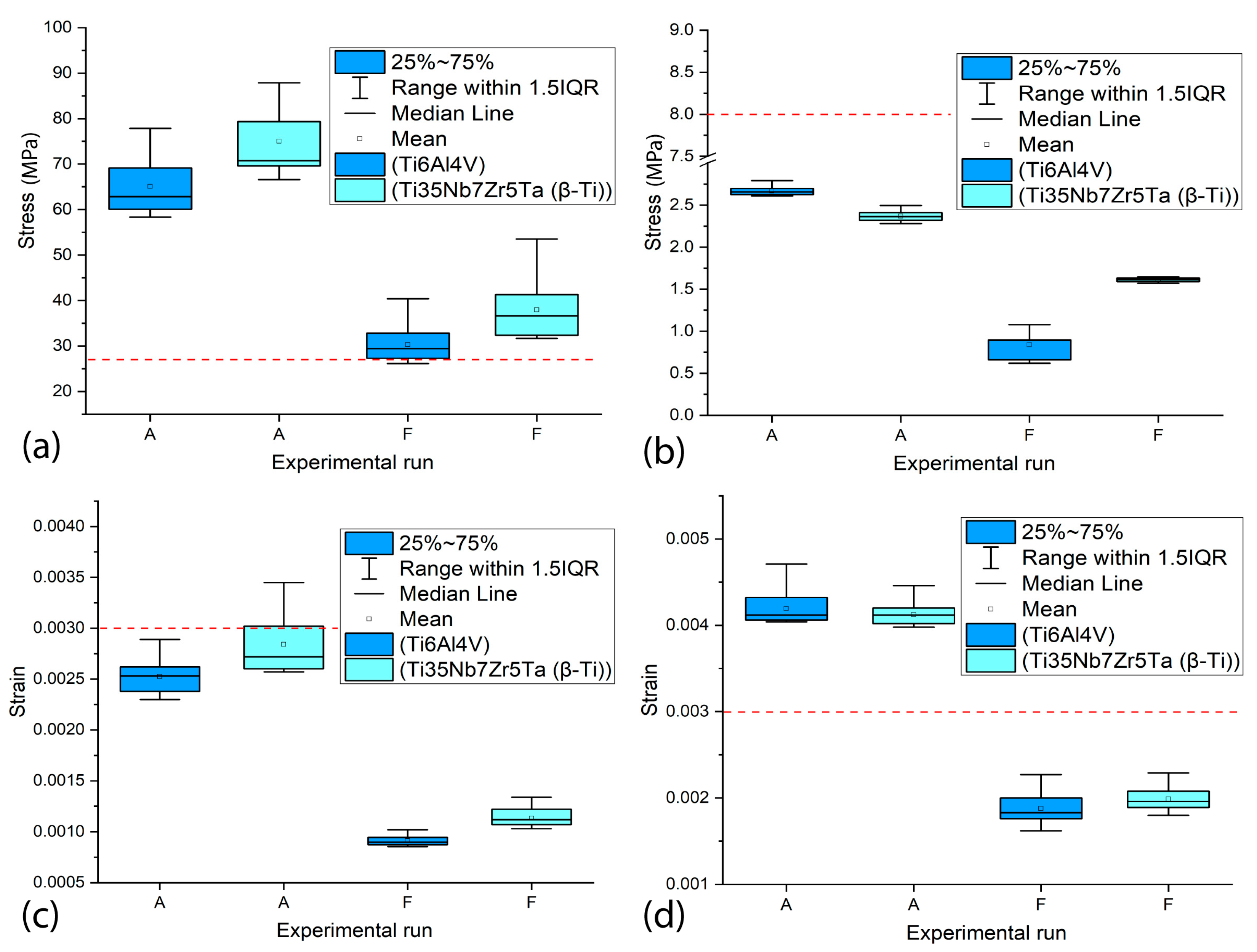
3.4. The Influence of the Type of Material on the Values of MVMES and MVMS in the Peri-Implant Bone

The influence of the two titanium alloys used in the simulations on the VMES and VMS generated in the peri-implant bone was analyzed. Figure 10 shows the range of VMES and VMS values obtained in the most loaded regions of the cortical bone (a and c) and the trabecular bone (b and d), resulting from experimental runs with smaller and larger-sized implants (A and F). In both regions, all variants exhibited statistically significant differences (p < 0.05).
The results demonstrate that the choice of titanium alloy significantly influences the magnitude of stresses and strains transmitted to the cortical bone. The Ti35Nb7Zr5Ta (β-Ti) alloy, characterized by a lower elastic modulus compared to Ti6Al4V, consistently generated higher stresses (90 MPa vs. 78 MPa in smaller-sized implants; 40 MPa vs. 30 MPa in larger-sized implants). This difference can be attributed to its greater flexibility, which reduces the overall stiffness of the implant–bone system, slightly increasing the load transfer to the adjacent bone tissue. However, this behavior does not necessarily represent a disadvantage as moderate mechanical stimulation could promote bone remodeling, provided that damage thresholds are not exceeded. Regarding strains, although β-Ti yielded slightly higher values (0.0030 vs. 0.0025 in smaller implants; 0.0012 vs. 0.0010 in larger implants), they never exceeded the physiological limit (0.003), suggesting that both alloys are mechanically biocompatible. Nevertheless, the lower stiffness of β-Ti could be advantageous in clinical scenarios aiming to mitigate stress-shielding effects, particularly in patients with low bone density.
In the trabecular bone, significant differences in biomechanical response were observed depending on the alloy used. For the smaller-sized implant, Ti6Al4V generated slightly higher stresses (2.7 MPa) compared to β-Ti (2.5 MPa), while in the larger-sized implant, the same behavior observed in cortical bone was maintained, with β-Ti showing higher values (1.7 MPa vs. 1 MPa for Ti6Al4V). Regarding strains, in the smaller implant experimental variants, similar values were obtained for both alloys (0.0044 for Ti6Al4V and 0.0042 for β-Ti) that slightly exceeded the physiological limits for maintaining bone density (0.003), which could potentially lead to bone loss due to mechanical overload. In contrast, the larger-sized implants maintained strains within the safe range (0.002–0.0022), although β-Ti again showed higher values.
The results demonstrate that the choice of titanium alloy significantly influences the biomechanical response of both cortical and trabecular bone. Due to its lower elastic modulus, the Ti35Nb7Zr5Ta alloy (β-Ti) generated different stress and strain values compared to Ti6Al4V, with a tendency to transfer higher loads to bone tissue. In cortical bone, this behavior remained within physiological limits for strain values, suggesting that β-Ti may reduce the risk of stress shielding. However, in trabecular bone, both materials induced critical strains in short implants, although β-Ti demonstrated better performance in terms of stress distribution. These findings highlight that while β-Ti offers theoretical advantages for bone remodeling, its clinical application requires careful consideration of implant design and patient bone quality to prevent harmful overloads, particularly in trabecular bone regions.
For the clinical implementation of the developing implant model, evidence suggests preferential selection of implant variants of maximum diameter and maximum length, contingent on adequate dimensions of the recipient jawbone. However, several study limitations constrain the direct clinical extrapolation of these findings. First, the simulation methodology used static loading conditions under delayed loading assumptions. Second, critical variables including peri-implant bone quality variations and implant positioning within the jaw were not incorporated in the biomechanical analysis. Consequently, future research should focus on (1) using FEM to investigate the effects of these unexamined variables on peri-implant stress/strain distributions and (2) validating current findings through experimental testing, including controlled in vivo experimentation.

4. Conclusions

This investigation employed finite element analysis to assess the biomechanical performance of a novel dental implant design, with particular focus on evaluating how the implant length and diameter influence MVMES and MVMS in peri-implant bone. The main findings are as follows:
  • Peak stress concentrations occurred in peri-implant cortical bone, particularly in the maxillary surface region adjacent to the implant neck. This mechanical behavior stems from the elevated Young’s modulus of the cortical bone, which enhances its load-bearing capacity. On the contrary, the maximum strain values were localized in the trabecular bone regions.
  • Both the implant diameter and length demonstrated statistically significant effects (p < 0.05) on the peak equivalent stress and strain values in cortical and trabecular bone.
  • Implant diameter emerged as the dominant variable affecting mechanical response, attributable to increased implant–bone contact area that promotes load dissipation and consequently reduces peri-implant stress/strain magnitudes.
  • Superior biomechanical outcomes consistently correlated with larger implant dimensions, suggesting enhanced clinical performance potential for crown–implant systems featuring maximum diameter and length configurations.
  • The material of the dental implant demonstrated a statistically significant influence (p < 0.05) on the maximum levels of stress and strain generated in the cortical and trabecular bones. In general, the Ti35Nb7Zr5Ta alloy implants showed higher maximum values of VMES and VMS than those generated by Ti6Al4V alloy implants.

Author Contributions

P.G.-M.: Conceptualization, Methodology, Investigation, Formal Analysis, Validation, and Writing—Original Draft. J.R.-G.: Investigation, Conceptualization, Methodology, Formal Analysis, Validation, and Writing—Original Draft. J.E.G.: Project Administration, Conceptualization, Methodology, Supervision, Writing—Original Draft, and Writing—Review and Editing. A.P.: Methodology, Writing—Original Draft, and Writing—Review and Editing. Y.T.: Conceptualization, Project Administration, Supervision, Methodology, Writing—Original Draft, and Writing—Review and Editing. All authors have read and agreed to the published version of the manuscript.

Funding

This publication is part of project PID2022-137911OB-I00, funded by MICIU/AEI/10.13039/501100011033 and by ERDF/EU. Also, the Ministry of Science and Innovation of Spain for their contribution to the project through grant PDC2022-133369-I00, as well as, the project PN385LH007-035: 9827 of the Cuban National Science and Technology program: Bio-technology, Pharmaceutical Industry, and Medical Technologies.

Institutional Review Board Statement

Not applicable.

Informed Consent Statement

Not applicable.

Data Availability Statement

The original contributions presented in this study are included in the article. Further inquiries can be directed to the corresponding authors.

Acknowledgments

The authors would like to thank the laboratory technicians at the University of Seville for their support in characterizing the implant prototypes under development to corroborate the results of the finite element models presented in this work.

Conflicts of Interest

The authors declare no conflicts of interest.

Abbreviations

The following abbreviations are used in this manuscript:
FEAFinite element analysis
VMESvon Mises equivalent stress
VMSvon Mises strain
MVMESMaximum von Mises equivalent stress
MVMSMaximum von Mises strain

References

  1. Alghamdi, H.S.; Jansen, J.A. The development and future of dental implants. Dent. Mater. J. 2020, 39, 167–172. [Google Scholar] [CrossRef] [PubMed]
  2. Bazli, L.; Khoramabadi, H.N.; Chahardehi, A.M.; Arsad, H.; Malekpouri, B.; Jazi, M.A.; Azizabadi, N. Factors influencing the failure of dental implants: A Systematic Review. J. Compos. Compd. 2019, 2, 18–25. [Google Scholar] [CrossRef]
  3. Yang, Y.; Hu, H.; Zeng, M.; Chu, H.; Gan, Z.; Duan, J.; Rong, M. The survival rates and risk factors of implants in the early stage: A retrospective study. BMC Oral Health 2021, 21, 293. [Google Scholar] [CrossRef]
  4. Hasanoglu Erbasar, G.N.; Hocaoğlu, T.P.; Erbasar, R.C. Risk factors associated with short dental implant success: A long-term retrospective evaluation of patients followed up for up to 9 years. Braz. Oral Res. 2019, 33, e030. [Google Scholar] [CrossRef] [PubMed]
  5. Krisam, J.; Ott, L.; Schmitz, S.; Klotz, A.-L.; Seyidaliyeva, A.; Rammelsberg, P.; Zenthöfer, A. Factors affecting the early failure of implants placed in a dental practice with a specialization in implantology–a retrospective study. BMC Oral Health 2019, 19, 208. [Google Scholar] [CrossRef]
  6. Nimbalkar, S.; Dhatrak, P.; Gherde, C.; Joshi, S. A review article on factors affecting bone loss in dental implants. Mater. Today Proc. 2021, 43, 970–976. [Google Scholar] [CrossRef]
  7. Şahin, T. The effect of individuals’ oral hygiene habits and knowledge levels on peri-implant health and disease: A questionnaire-based observational study. BMC Oral Health 2024, 24, 443. [Google Scholar] [CrossRef]
  8. Malmqvist, S.; Erdenborg, J.; Johannsen, G.; Johannsen, A. Patient’s experiences of dental implants, peri-implantitis and its treatment-A qualitative interview study. Int. J. Dent. Hyg. 2024, 22, 530–539. [Google Scholar] [CrossRef]
  9. Cortellini, S.; Favril, C.; De Nutte, M.; Teughels, W.; Quirynen, M. Patient compliance as a risk factor for the outcome of implant treatment. Periodontology 2000 2019, 81, 209–225. [Google Scholar] [CrossRef]
  10. Sadowsky, S.J. Occlusal overload with dental implants: A review. Int. J. Implant Dent. 2019, 5, 29. [Google Scholar] [CrossRef]
  11. Robinson, D.; Aguilar, L.; Gatti, A.; Abduo, J.; Lee, P.V.S.; Ackland, D. Load response of the natural tooth and dental implant: A comparative biomechanics study. J. Adv. Prosthodont. 2019, 11, 169–178. [Google Scholar] [CrossRef] [PubMed]
  12. Szajek, K.; Wierszycki, M. Screw preload loss under occlusal load as a predictor of loosening risk in varying dental implant designs. J. Mech. Behav. Biomed. Mater. 2023, 148, 106165. [Google Scholar] [CrossRef]
  13. Pérez-Pevida, E.; Chávarri-Prado, D.; Diéguez-Pereira, M.; Estrada-Martínez, A.; Montalbán-Vadillo, O.; Jiménez-Garrudo, A. Consequences of peri-implant bone loss in the occlusal load transfer to the supporting bone in terms of magnitude of stress, strain, and stress distribution: A finite element analysis. BioMed Res. Int. 2021, 2021, 3087071. [Google Scholar] [CrossRef] [PubMed]
  14. Delgado-Ruiz, R.A.; Calvo-Guirado, J.L.; Romanos, G.E. Effects of occlusal forces on the peri-implant-bone interface stability. Periodontology 2000 2019, 81, 179–193. [Google Scholar] [CrossRef]
  15. Bagegni, A.; Abou-Ayash, S.; Rücker, G.; Algarny, A.; Att, W. The influence of prosthetic material on implant and prosthetic survival of implant-supported fixed complete dentures: A systematic review and meta-analysis. J. Prosthodont. Res. 2019, 63, 251–265. [Google Scholar] [CrossRef]
  16. Misch, C.E.; Resnik, R.R. Available bone and dental implant treatmentplans. In Misch’s Contemporary Implant Dentistry, 4th ed.; Elsevier: Amsterdam, The Netherlands, 2020; p. 415. [Google Scholar]
  17. Rues, S.; Schmitter, M.; Kappel, S.; Sonntag, R.; Kretzer, J.P.; Nadorf, J. Effect of bone quality and quantity on the primary stability of dental implants in a simulated bicortical placement. Clin. Oral Investig. 2020, 25, 1265–1272. [Google Scholar] [CrossRef] [PubMed]
  18. Kowalski, J.; Lapinska, B.; Nissan, J.; Lukomska-Szymanska, M. Factors Influencing Marginal Bone Loss around Dental Implants: A Narrative Review. Coatings 2021, 11, 865. [Google Scholar] [CrossRef]
  19. Di Stefano, D.A.; Arosio, P.; Capparè, P.; Barbon, S.; Gherlone, E.F. Gherlone, Stability of dental implants and thickness of cortical bone: Clinical research and future perspectives. A systematic review. Materials 2021, 14, 7183. [Google Scholar] [CrossRef]
  20. Clarot, S.; Christensen, B.J.; Chapple, A.G.; Block, M.S. Block, Prediction of residual alveolar bone height in the posterior maxilla after dental extractions. J. Oral Maxillofac. Surg. 2021, 80, 517–524. [Google Scholar] [CrossRef]
  21. Toledano, M.; Fernández-Romero, E.; Vallecillo, C.; Toledano, R.; Osorio, M.T.; Vallecillo-Rivas, M. Short versus standard implants at sinus augmented sites: A systematic review and meta-analysis. Clin. Oral Investig. 2022, 26, 6681–6698. [Google Scholar] [CrossRef]
  22. Park, S.; Park, J.; Kang, I.; Lee, H.; Noh, G. Effects of assessing the bone remodeling process in biomechanical finite element stability evaluations of dental implants. Comput. Methods Programs Biomed. 2022, 221, 106852. [Google Scholar] [CrossRef]
  23. Irandoust, S.; Müftü, S. The interplay between bone healing and remodeling around dental implants. Sci. Rep. 2020, 10, 4335. [Google Scholar] [CrossRef] [PubMed]
  24. Flanagan, D. Osseous remodeling around dental implants. J. Oral Implant. 2019, 45, 239–246. [Google Scholar] [CrossRef] [PubMed]
  25. Gherde, C.; Dhatrak, P.; Nimbalkar, S.; Joshi, S. A comprehensive review of factors affecting fatigue life of dental implants. Mater. Today Proc. 2020, 43, 1117–1123. [Google Scholar] [CrossRef]
  26. Ziaie, B.; Khalili, S.M.R. Evaluation of fatigue life for dental implants using FEM analysis. Prosthesis 2021, 3, 300–313. [Google Scholar] [CrossRef]
  27. Arai, Y.; Takashima, M.; Matsuzaki, N.; Takada, S. Marginal bone loss in dental implants: A literature review of risk factors and treatment strategies for prevention. J. Prosthodont. Res. 2024, 69, 12–20. [Google Scholar] [CrossRef]
  28. Guven, S.S.; Cabbar, F.; Guler, N. Local and systemic factors associated with marginal bone loss around dental implants: A retrospective clinical study. Quintessence Int. 2020, 51, 128–141. [Google Scholar]
  29. Alemayehu, D.-B.; Jeng, Y.-R. Three-dimensional finite element investigation into effects of implant thread design and loading rate on stress distribution in dental implants and anisotropic bone. Materials 2021, 14, 6974. [Google Scholar] [CrossRef] [PubMed]
  30. Ishak, M.I.; Daud, R.; Ibrahim, I.; Mat, F.; Mansor, N.N. Mansor, Biomechanical overloading factors influencing the failure of dental implants: A review. In Symposium on Damage Mechanism in Materials and Structures; Springer: Berlin/Heidelberg, Germany, 2020; pp. 127–142. [Google Scholar]
  31. Lovatto, S.T.; Bassani, R.; Sarkis-Onofre, R.; dos Santos, M.B.F. Influence of different implant geometry in clinical longevity and maintenance of marginal bone: A systematic review. J. Prosthodont. 2018, 28, e713–e721. [Google Scholar] [CrossRef]
  32. Filho, L.C.D.C.; Faot, F.; Madruga, M.d.M.; Marcello-Machado, R.M.; Bordin, D.; Cury, A.A.D.B. Effect of implant macrogeometry on peri-implant healing outcomes: A randomized clinical trial. Clin. Oral Investig. 2018, 23, 567–575. [Google Scholar] [CrossRef]
  33. Kreve, S.; Ferreira, I.; Valente, M.L.d.C.; dos Reis, A.C. Relationship between dental implant macro-design and osseointegration: A systematic review. Oral Maxillofac. Surg. 2022, 28, 1–14. [Google Scholar] [CrossRef] [PubMed]
  34. Herrero-Climent, M.; López-Jarana, P.; Lemos, B.F.; Gil, F.J.; Falcão, C.; Ríos-Santos, J.V.; Ríos-Carrasco, B. Relevant design aspects to improve the stability of titanium dental implants. Materials 2020, 13, 1910. [Google Scholar] [CrossRef]
  35. Anitua, E.; de Ibarra, N.L.S.; Martín, I.M.; Rotaeche, L.S. Influence of dental implant diameter and bone quality on the biomechanics of single-crown restoration. A finite element analysis. Dent. J. 2021, 9, 103. [Google Scholar] [CrossRef] [PubMed]
  36. Elleuch, S.; Jrad, H.; Kessentini, A.; Wali, M.; Dammak, F. Design optimization of implant geometrical characteristics enhancing primary stability using FEA of stress distribution around dental prosthesis. Comput. Methods Biomech. Biomed. Eng. 2021, 24, 1035–1051. [Google Scholar] [CrossRef]
  37. Büyük, F.N.; Savran, E.; Karpat, F. Review on finite element analysis of dental implants. J. Dent. Implant Res. 2022, 41, 50–63. [Google Scholar] [CrossRef]
  38. Falcinelli, C.; Valente, F.; Vasta, M.; Traini, T. Finite element analysis in implant dentistry: State of the art and future directions. Dent. Mater. 2023, 39, 539–556. [Google Scholar] [CrossRef] [PubMed]
  39. Kudagi, V.; Shivakumar, S.; Talwade, P. Applications of finite element analysis in dentistry: A review. J. Int. Oral Health 2021, 13, 415–422. [Google Scholar] [CrossRef]
  40. Castilla, R.; Forero, L.; González-Estrada, O.A. Comparative study of the influence of dental implant design on the stress and strain distribution using the finite element method. J. Phys. Conf. Ser. 2019, 1159, 012016. [Google Scholar] [CrossRef]
  41. Andreevich, S.Y.; Zurabovich, C.D.; Mikhailovich, A.V. The usage of the finite element analysis in the design of new dental implant systems. Int. J. Innov. Med. 2023, 1, 19–23. [Google Scholar]
  42. Lee, H.; Jo, M.; Noh, G. Biomechanical effects of dental implant diameter, connection type, and bone density on microgap formation and fatigue failure: A finite element analysis. Comput. Methods Programs Biomed. 2021, 200, 105863. [Google Scholar] [CrossRef]
  43. Fiorillo, L.; Cicciù, M.; D’amico, C.; Mauceri, R.; Oteri, G.; Cervino, G. Finite element method and von mises investigation on bone response to dynamic stress with a novel conical dental implant connection. BioMed Res. Int. 2020, 2020, 2976067. [Google Scholar] [CrossRef] [PubMed]
  44. Pammer, D. Evaluation of postoperative dental implant primary stability using 3D finite element analysis. Comput. Methods Biomech. Biomed. Eng. 2019, 22, 280–287. [Google Scholar] [CrossRef] [PubMed]
  45. Shakir, S.M.; Muhsin, S.A.; Al Marza, R. Finite Element Modelling Based Studies for Dental Implants: Systematic Review. J. Tech. 2022, 4, 155–169. [Google Scholar] [CrossRef]
  46. Vanaclocha, V.; Atienza, C.; Vanaclocha, A.; Peñuelas, A.; Gómez-Herrero, J.; Pérez-Carrió, F.; Diego-Leyda, J.A.; Sáiz-Sapena, N.; Vanaclocha, L. New Subperiosteal Dental Implant Design with Finite Element Analysis and Mechanical Validation: A Design Validation Study. Materials 2025, 18, 622. [Google Scholar] [CrossRef]
  47. Cheng, Y.-C.; Lin, D.-H.; Jiang, C.-P.; Lee, S.-Y. Design improvement and dynamic finite element analysis of novel ITI dental implant under dynamic chewing loads. Bio-Med. Mater. Eng. 2015, 26, S555–S561. [Google Scholar] [CrossRef]
  48. Dommeti, V.K.; Pramanik, S.; Roy, S. Design of customized coated dental implants using finite element analysis. Dent. Med. Probl. 2023, 60, 385–392. [Google Scholar] [CrossRef]
  49. Patil, V.; Naik, N. A comparative study on the effect of stress in dental implant structure using finite element analysis. Int. J. Mech. Prod. Eng. Res. Dev. 2019, 9, 709–717. [Google Scholar]
  50. Neto, J.V.C.; Celles, C.A.S.; de Andrade, C.S.A.F.; Afonso, C.R.M.; Nagay, B.E.; Barão, V.A.R. Recent advances and prospects in β-type titanium alloys for dental implants applications. ACS Biomater. Sci. Eng. 2024, 10, 6029–6060. [Google Scholar] [CrossRef]
  51. Mao, C.; Yu, W.; Jin, M.; Wang, Y.; Shang, X.; Lin, L.; Zeng, X.; Wang, L.; Lu, E. Mechanobiologically optimized Ti–35Nb–2Ta–3Zr improves load transduction and enhances bone remodeling in tilted dental implant therapy. Bioact. Mater. 2022, 16, 15–26. [Google Scholar]
  52. Alevizakos, V.; Mitov, G.; Ahrens, A.; von See, C. The influence of implant site preparation and sterilization on the performance and wear of implant drills. Int. J. Oral Maxillofac. Implant 2021, 36, 546–552. [Google Scholar] [CrossRef]
  53. Nandini, N.; Kunusoth, R.; Alwala, A.M.; Prakash, R.; Sampreethi, S.; Katkuri, S. Cylindrical Implant Versus Tapered Implant: A Comparative Study. Cureus 2022, 14, e29675. [Google Scholar] [CrossRef] [PubMed]
  54. Rugova, S.; Abboud, M. Thermal Evaluation of Bone Drilling with a One-Drill Protocol. Bioengineering 2024, 11, 1022. [Google Scholar] [CrossRef] [PubMed]
  55. obau-Porrua, A.; González, J.E.; Rodríguez-Guerra, J.; González-Mederos, P.; Navarro, P.; de la Rosa, J.E.; Carbonell-González, M.; Araneda-Hernández, E.; Torres, Y. Biomechanical behavior of a new design of dental implant: Influence of the porosity and location in the maxilla. J. Mater. Res. Technol. 2024, 29, 3255–3267. [Google Scholar] [CrossRef]
  56. Robau-Porrua, A.; González, J.E.; Arancibia-Castillo, R.; Picardo, A.; Araneda-Hernández, E.; Torres, Y. Design, fabrication, and characterization of novel dental implants with porosity gradient obtained by Selective Laser Melting. Mater. Des. 2025, 251, 113660. [Google Scholar]
  57. Rodríguez, Y.; Ruíz, J.G.; Ruiz-Valverde, O.; Pérez-Álvarez, M. Simulation of the influence of the platform switching of a model of dental implant on the bio-mechanics of maxillary bones. In Proceedings of the Dental Implants, Chicago, IL, USA, 29 November 2018. [Google Scholar]
  58. Pérez-Pevida, E.; Brizuela-Velasco, A.; Chávarri-Prado, D.; Jiménez-Garrudo, A.; Sánchez-Lasheras, F.; Solaberrieta-Méndez, E.; Diéguez-Pereira, M.; Fernández-González, F.J.; Dehesa-Ibarra, B.; Monticelli, F. Biomechanical Consequences of the Elastic Properties of Dental Implant Alloys on the Supporting Bone: Finite Element Analysis. BioMed Res. Int. 2016, 2016, 1850401. [Google Scholar] [CrossRef]
  59. Elhadad, A.A.; Romero-Resendiz, L.; Rossi, M.; Rodríguez-Albelo, L.; Lascano, S.; Afonso, C.R.; Alcudia, A.; Amigó, V.; Torres, Y. Findings and perspectives of β-Ti alloys with biomedical applications: Exploring beyond biomechanical and biofunctional behaviour. J. Mater. Res. Technol. 2024, 33, 3550–3618. [Google Scholar] [CrossRef]
  60. Pellizzer, E.P.; Lemos, C.A.A.; Almeida, D.A.F.; Batista, V.E.D.S.; Júnior, J.F.S.; Verri, F.R. Biomechanical analysis of different implant-abutments interfaces in different bone types: An in silico analysis. Mater. Sci. Eng. C 2018, 90, 645–650. [Google Scholar] [CrossRef]
  61. Hussein, M.O. Biomechanical analysis of different implant-overdenture loading protocols under dynamic loads. J. Am. Sci. 2013, 9, 8. [Google Scholar]
  62. Himmlová, L.; Dostálová, T.; Kácovský, A.; Konvičková, S. Influence of implant length and diameter on stress distribution: A finite element analysis. J. Prosthet. Dent. 2004, 91, 20–25. [Google Scholar] [CrossRef]
  63. Yemineni, B.C.; Mahendra, J.; Nasina, J.; Mahendra, L.; Shivasubramanian, L.; Perika, S.B. Evaluation of maximum principal stress, von mises stress, and deformation on surrounding mandibular bone during insertion of an implant: A three-dimensional finite element study. Cureus 2020, 12, e9430. [Google Scholar] [CrossRef]
  64. Tretto, P.H.W.; dos Santos, M.B.F.; Spazzin, A.O.; Pereira, G.K.R.; Bacchi, A. Assessment of stress/strain in dental implants and abutments of alternative materials compared to conventional titanium alloy—3D non-linear finite element analysis. Comput. Methods Biomech. Biomed. Eng. 2020, 23, 372–383. [Google Scholar] [CrossRef] [PubMed]
  65. Li, J.; Jansen, J.A.; Walboomers, X.F.; van den Beucken, J.J. Mechanical aspects of dental implants and osseointegration: A narrative review. J. Mech. Behav. Biomed. Mater. 2020, 103, 103574. [Google Scholar] [CrossRef] [PubMed]
  66. Gao, X.; Fraulob, M.; Haïat, G. Biomechanical behaviours of the bone–implant interface: A review. J. R. Soc. Interface 2019, 16, 20190259. [Google Scholar] [CrossRef]
  67. Li, R.; Wu, Z.; Chen, S.; Li, X.; Wan, Q.; Xie, G.; Pei, X. Biomechanical behavior analysis of four types of short implants with different placement depths using the finite element method. J. Prosthet. Dent. 2023, 129, 447.e1–447.e10. [Google Scholar] [CrossRef]
  68. Robau-Porrua, A.; Pérez-Rodríguez, Y.; Soris-Rodríguez, L.M.; Pérez-Acosta, O.; González, J.E. The effect of diameter, length and elastic modulus of a dental implant on stress and strain levels in peri-implant bone: A 3D finite element analysis. Bio-Med. Mater. Eng. 2020, 30, 541–558. [Google Scholar] [CrossRef]
  69. Song, K.; Wang, Z.; Lan, J.; Ma, S. Porous structure design and mechanical behavior analysis based on TPMS for customized root analogue implant. J. Mech. Behav. Biomed. Mater. 2021, 115, 104222. [Google Scholar] [CrossRef]
  70. Martins, D.; Couto, R.; Fonseca, E.M.; Carreiras, A.R. Numerical analysis of the mechanical stimuli transferred from a dental implant to the bone. J. Comput. Appl. Res. Mech. Eng. (JCARME) 2021, 11, 1–11. [Google Scholar]
  71. Frost, H.M. Bone’s mechanostat: A 2003 update, The Anatomical record part a: Discoveries in molecular, cellular, and evolutionary biology: An official publication of the american association of anatomists. Anat. Rec. 2003, 275, 1081–1101. [Google Scholar] [CrossRef]
  72. Baggi, L.; Cappelloni, I.; Di Girolamo, M.; Maceri, F.; Vairo, G. The influence of implant diameter and length on stress distribution of osseointegrated implants related to crestal bone geometry: A three-dimensional finite element analysis. J. Prosthet. Dent. 2008, 100, 422–431. [Google Scholar] [CrossRef]
  73. Ding, X.; Liao, S.; Zhu, X.; Zhang, X.; Zhang, L. Effect of diameter and length on stress distribution of the alveolar crest around immediate loading implants. Clin. Implant Dent. Relat. Res. 2009, 11, 279–287. [Google Scholar] [CrossRef]
  74. Muangsisied, S.; Chantarapanich, N.; Veerasakul, M.S.; Inglam, S. Effect of implant diameter and cortical bone thickness on biomechanical performance of short dental implant-supported distal cantilever: A finite element study. Eng. J. 2021, 25, 175–182. [Google Scholar] [CrossRef]
  75. Premnath, K.; Sridevi, J.; Kalavathy, N.; Nagaranjani, P.; Sharmila, M.R. Evaluation of stress distribution in bone of different densities using different implant designs: A three-dimensional finite element analysis. J. Indian Prosthodont. Soc. 2012, 13, 555–559. [Google Scholar] [CrossRef] [PubMed]
  76. Liao, S.-H.; Zhu, X.-H.; Xie, J.; Sohodeb, V.K.; Ding, X. Influence of Trabecular Bone on Peri-Implant Stress and Strain Based on Micro-CT Finite Element Modeling of Beagle Dog. BioMed Res. Int. 2016, 2016, 3926941. [Google Scholar] [CrossRef] [PubMed]
  77. Yuan, X.; Liu, Y.; Yang, Y.; Ren, M.; Luo, L.; Zheng, L.; Liu, Y. Effect of short implant crown-to-implant ratio on stress distribution in anisotropic bone with different osseointegration rates. BMC Oral Health 2023, 23, 683. [Google Scholar] [CrossRef]
  78. Li, J.; Li, H.; Shi, L.; Fok, A.S.; Ucer, C.; Devlin, H.; Horner, K.; Silikas, N. A mathematical model for simulating the bone remodeling process under mechanical stimulus. Dent. Mater. 2007, 23, 1073–1078. [Google Scholar] [CrossRef]
Figure 1. The cylindrical implant design used in the simulations and its main parameters.
Materials 18 02692 g001
Figure 2. The anchorage of the dental implant in the maxilla with the system mesh (a) and boundary conditions and the direction of the loads used in the simulations (b).
Materials 18 02692 g002
Figure 3. The distribution of von Mises equivalent stresses in the external surface of cortical bone surrounding the Ti6Al4V (α+β Ti) dental implant. Note: The letters indicate the experimental run (see Table 1).
Materials 18 02692 g003
Figure 4. The von Mises strain distribution in the external surface of cortical bone adjacent to the Ti6Al4V (α + β Ti) dental implant. The letters indicate the experimental run (see Table 1).
Materials 18 02692 g004
Figure 5. The distribution of von Mises equivalent stresses (S) and von Mises strains (E) in the external surface of peri-implant cortical bone using the Ti35Nb7Zr5Ta (β-Ti) implant. The letters indicate the experimental run (see Table 1).
Materials 18 02692 g005
Figure 6. The distribution of von Mises equivalent stresses in the trabecular bone using Ti6Al4V (α+β Ti). The letters indicate the experimental run (see Table 1).
Materials 18 02692 g006
Figure 7. The von Mises strain distribution in trabecular bone using Ti6Al4V (α+β Ti). The letters indicate the experimental run (see Table 1).
Materials 18 02692 g007
Figure 8. The distribution of von Mises equivalent stresses (S) and von Mises equivalent strains (E) in trabecular bone using Ti35Nb7Zr5Ta (β-Ti). The letters indicate the experimental run (see Table 1).
Materials 18 02692 g008
Figure 9. The range of stresses and strains in the most loaded areas of the peri-implant bone using Ti6Al4V (α+β Ti). (a,c) In the cortical bone; (b,d) in the trabecular bone. Note: The asterisks indicate that there are no statistically significant differences between the experimental runs, and the red line represents the recommended upper limit.
Materials 18 02692 g009
Figure 10. The range of stresses and strains in the most loaded areas of the peri-implant bone for experimental runs with smaller and larger-sized implants (A and F runs). (a,c) In the cortical bone; (b,d) in the trabecular bone. Note: The red line is the recommended upper limit.
Materials 18 02692 g010
Table 1. Experimental design.
Experimental RunImplant Parameter
D (mm)L (mm)
A3.78
B3.710
C3.712
D4.08
E4.010
F4.012
Table 2. The properties of the materials used in the system components.
MaterialYoung’s Modulus,
E (MPa)
Shear Modulus,
G (MPa)
Poisson’s Ratio,
ν
References
Ti6Al4V
(dental implant)
110,000-0.32[58]
Ti35Nb7Zr5Ta (β-Ti)
(dental implant)
55,000-0.32[59]
Feldspathic ceramic
(crown)
82,800-0.35[60]
Cortical boneEx = 17,900 *
Ey = 26,600
Ez = 12,500
Gyx = 4500
Gyz = 7100
Gxz= 5300
νxy = 0.26
νxz = 0.31
νyz = 0.28
[61]
Trabecular boneEx = 1148
Ey = 1148
Ez = 21
Gyx = 68
Gyz = 434
Gxz = 68
νxy = 0.05
νxz = 0.055
νyz = 0.322
* X—bucco-lingual direction; Y—mesio-distal direction; Z—axial direction (infero-superior).
Disclaimer/Publisher’s Note: The statements, opinions and data contained in all publications are solely those of the individual author(s) and contributor(s) and not of MDPI and/or the editor(s). MDPI and/or the editor(s) disclaim responsibility for any injury to people or property resulting from any ideas, methods, instructions or products referred to in the content.

