
Impact of Degraded Aviation Paints on the Aerodynamic Performance of Aircraft Skin

 , , , ,
  and
and 
Abstract

1. Introduction
2. Materials and Methods
3. Results
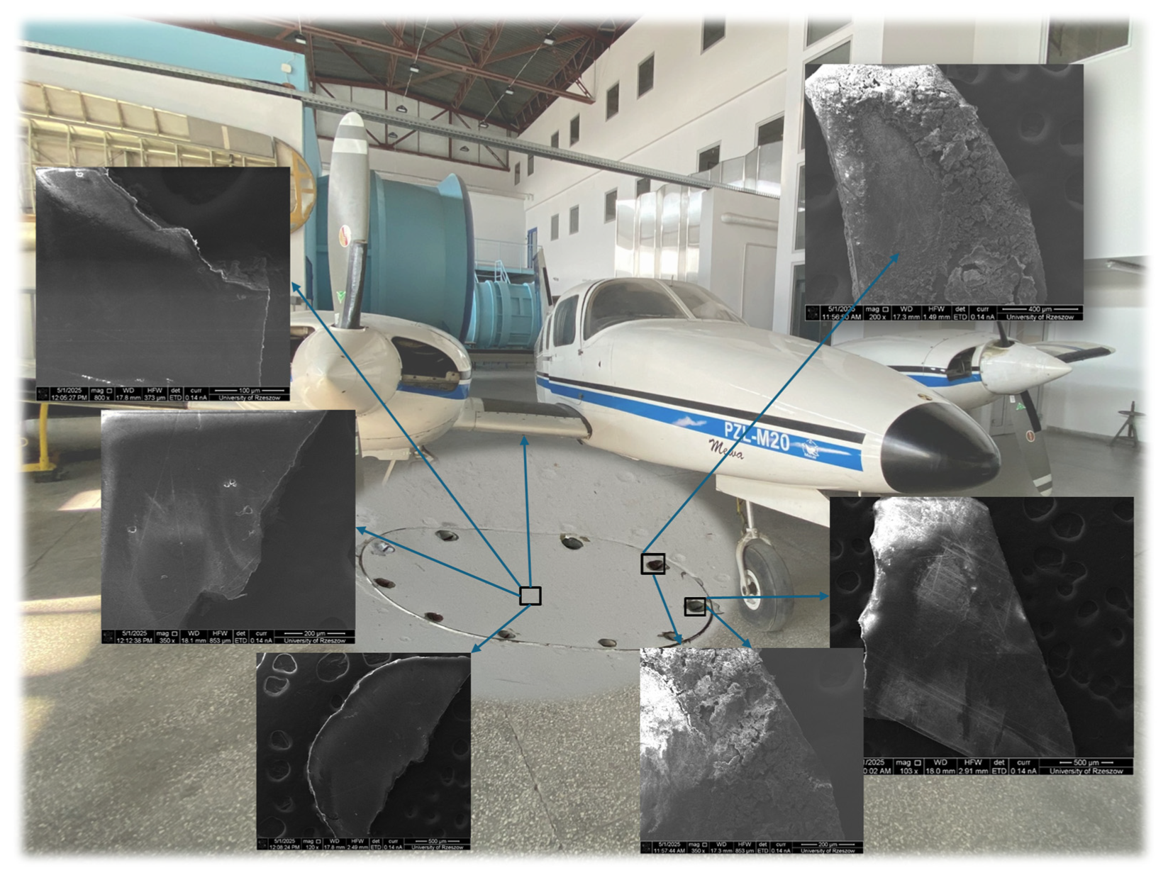
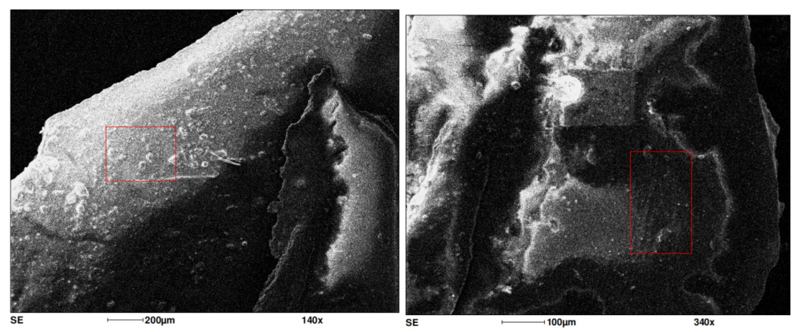
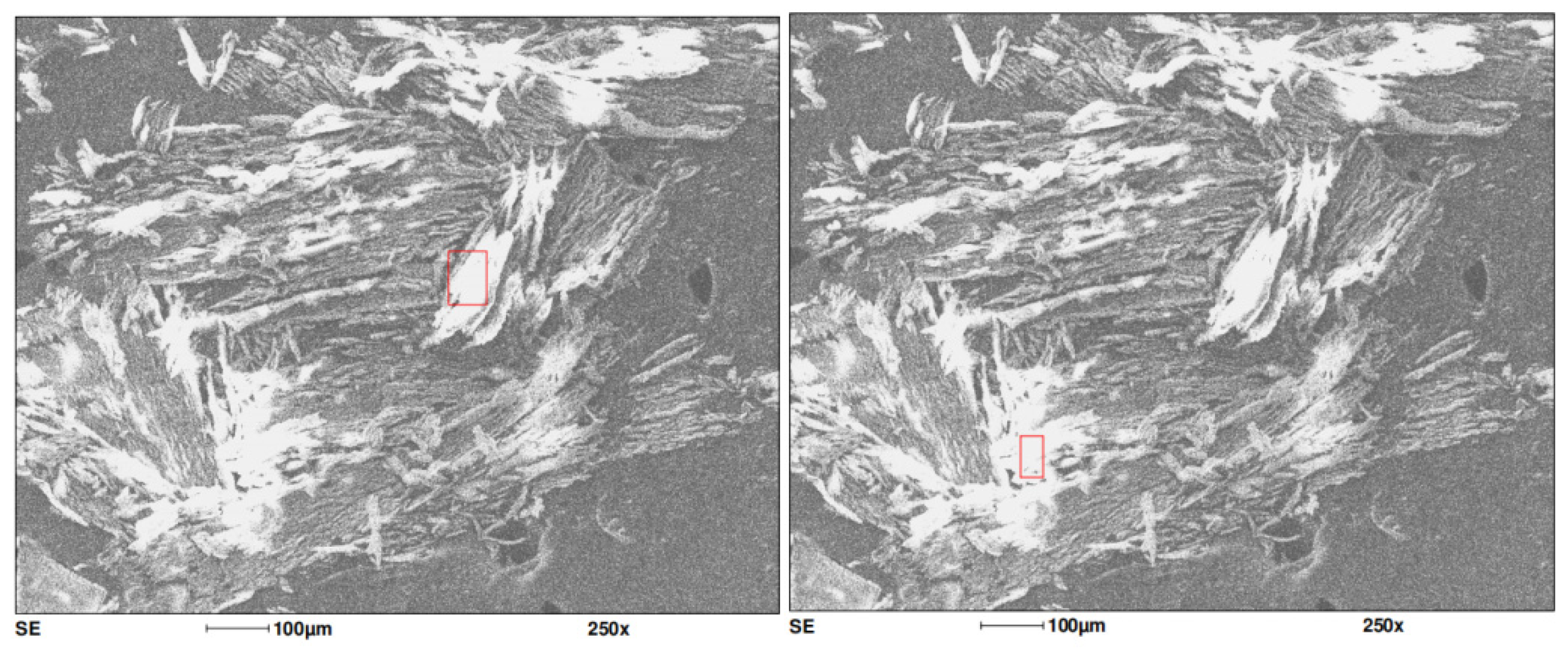
3.1. Scanning Electron Microscope
3.2. Analysis of Detected Elements in Paint Samples
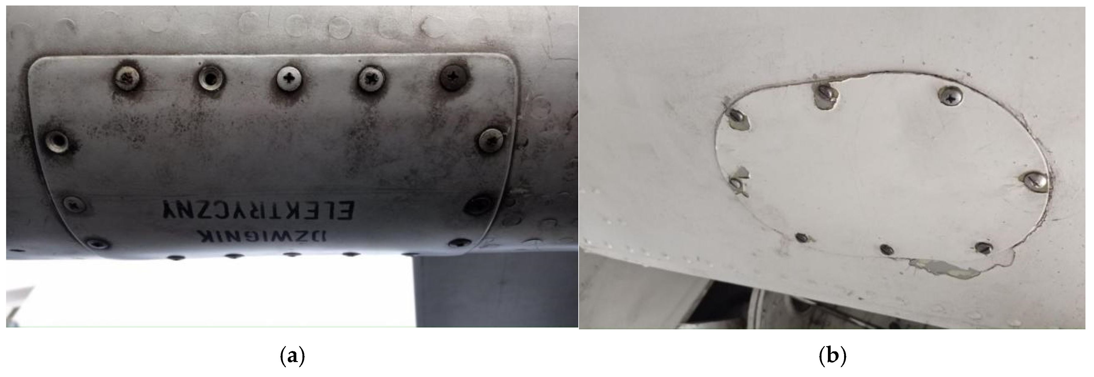
- Magnesium and iron: These may derive from corrosion products of other metal components or from environmental contaminants. The presence of these elements may suggest that the surface was not adequately prepared prior to painting. Residues of salts, dust, or other contaminants may have remained on the surface, potentially leading to adhesion issues with the paint.
- Degradation of protective coating: the paint, as a protective coating, may degrade over time due to atmospheric, chemical, or mechanical factors, which can lead to exposure to corrosion.
- Chemical reactions: phosphorus and sulfur may originate from industrial pollutants or be products of chemical reactions occurring on the metal surface in the presence of paint and the external environment.
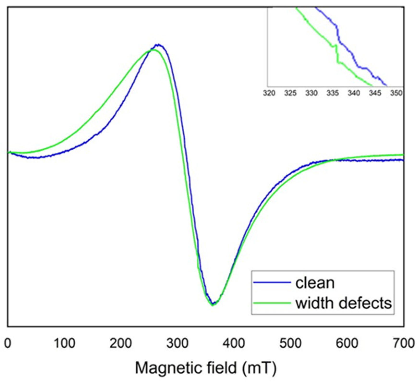
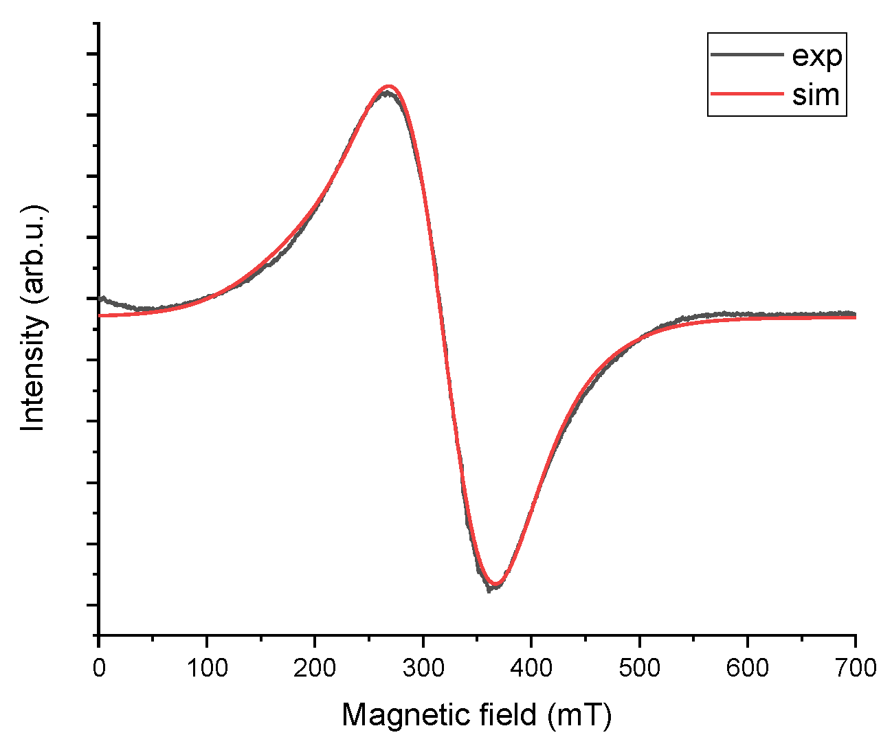
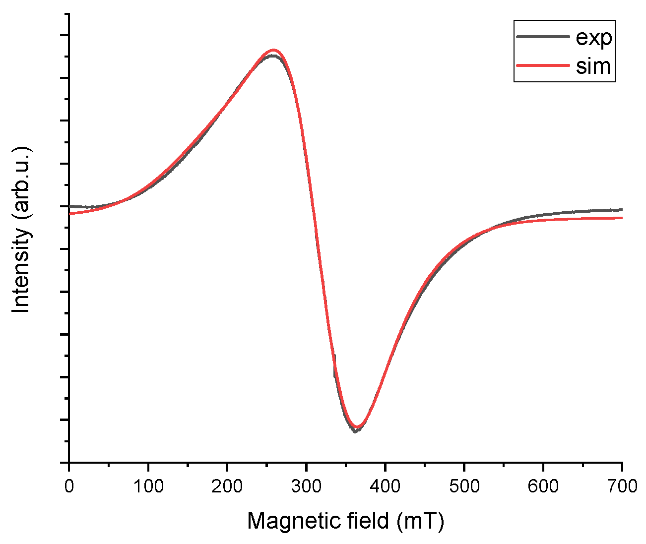
3.3. EPR Measurements
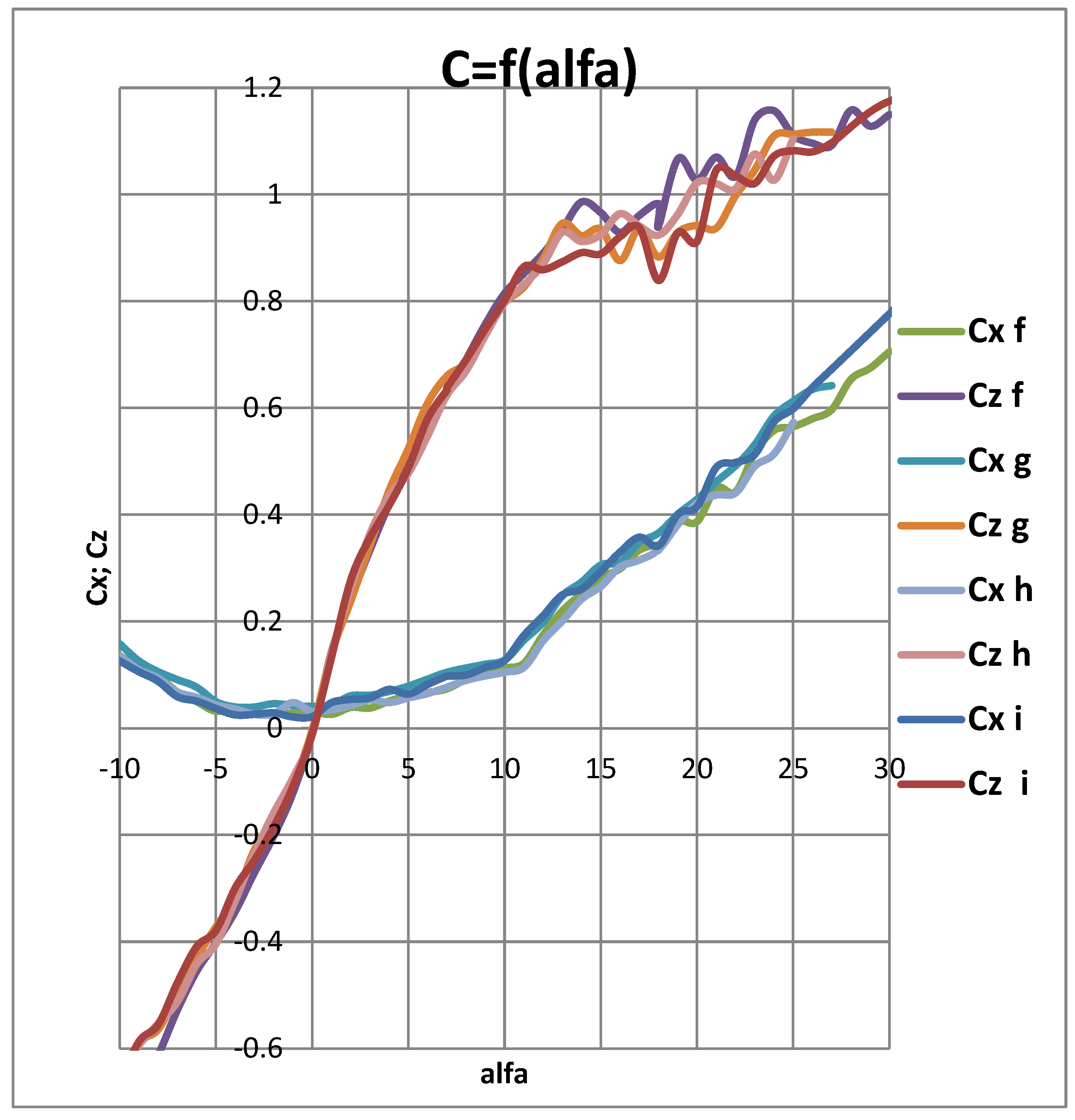
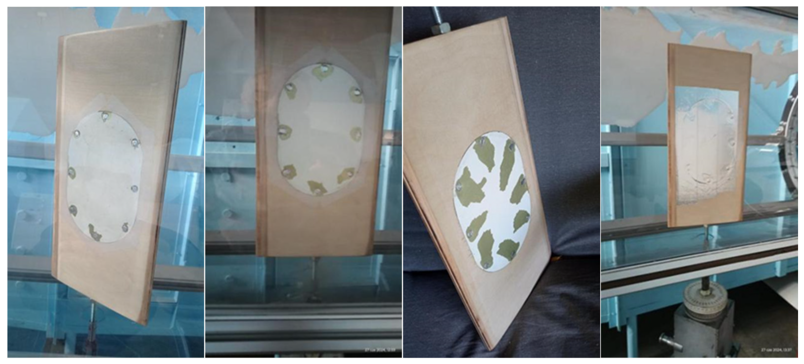
3.4. Comparison of Aerodynamic Characteristics of Selected Elements, Models Without and with Paint Coating Damage
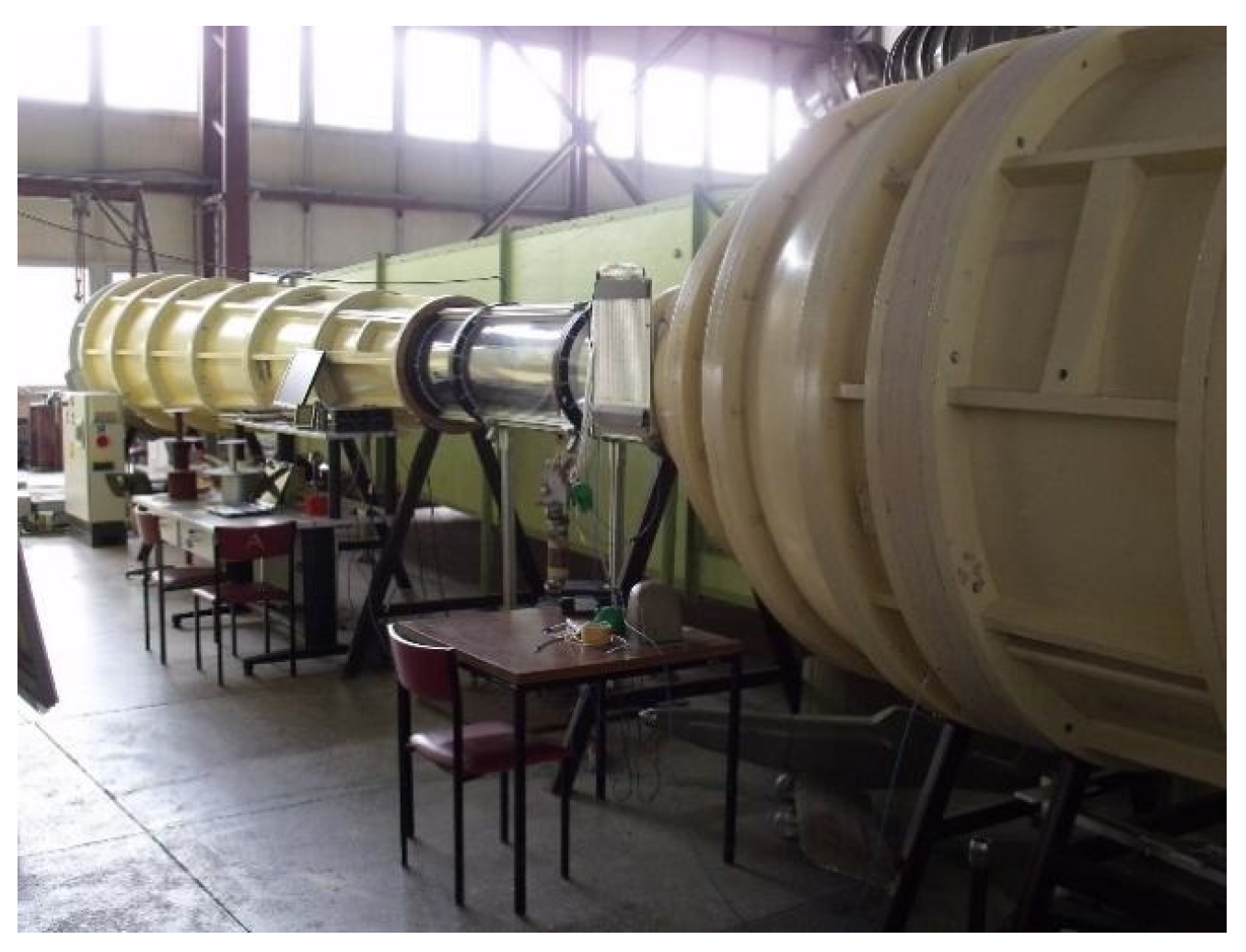
- Test conditions:
- The determined air density is ρ = 1.16 kg/m3;
- The Reynolds number is Re = 346,000 with respect to the model’s chord.
- The study was conducted for four cases:
- h-profile without defects;
- f-profile with the first level of paint loss;
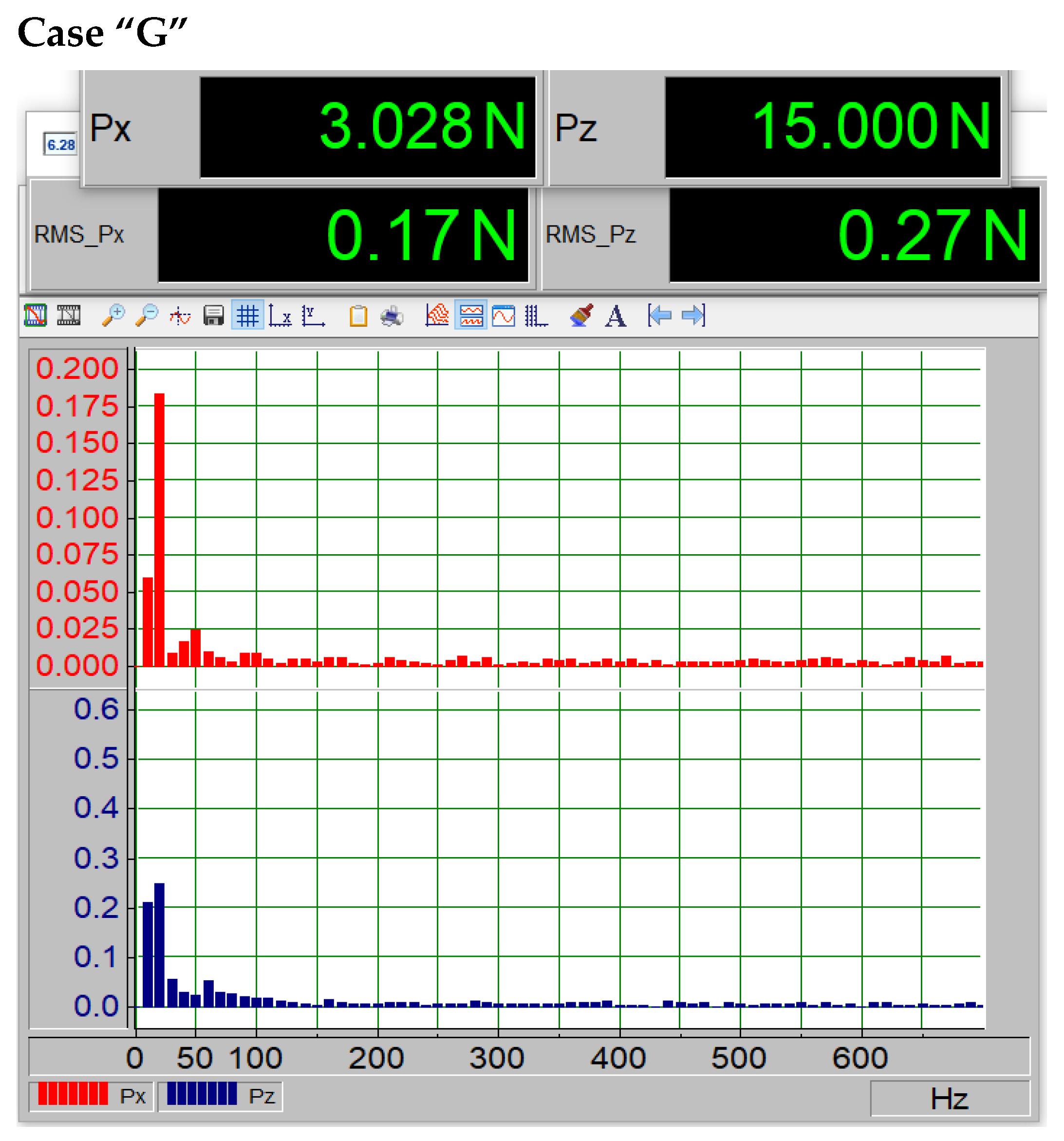
- g-second level of paint surface loss;
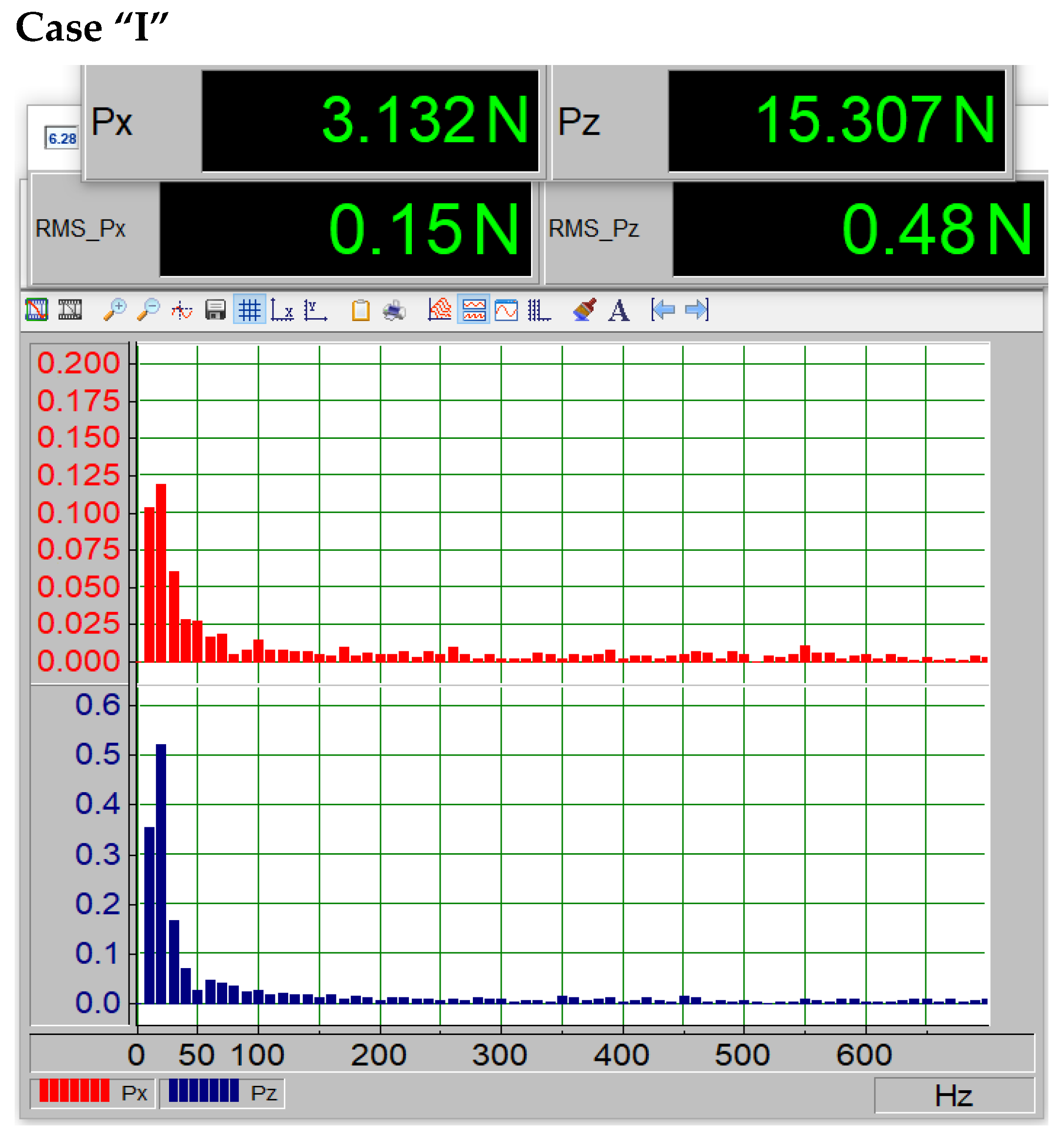
- i-third level of paint surface loss.
- h-profile without defects;
- f-profile with the first level of paint loss;
- g-second level of paint surface loss;
- i-third level of paint surface loss.
4. Conclusions
Author Contributions
Funding
Institutional Review Board Statement
Informed Consent Statement
Data Availability Statement
Conflicts of Interest
References
- The Business Research Company. Aircraft Paint Global Market Report; The Business Research Company: Clifton Heights, PA, USA, 2024. [Google Scholar]
- U.S. Department of Transportation, Federal Aviation Administration. Advisory Circular, Inspection, Prevention, Control, and Repair of Corrosion on Avionics Equipment, AC 43-206; U.S. Department of Transportation, Federal Aviation Administration: Washington, DC, USA, 2001.
- Federal Aviation Administration. Aerodynamics of Flight; Federal Aviation Administration: Washington, DC, USA, 2023; Chapter 5.
- Benavides, S. Corrosion Control in the Aerospace Industry; Woodhead Publishing Series in Metals and Surface Engineering; Woodhead Publishing Limited: Sawston, UK, 2009; ISBN 978-1-84569-345-9. [Google Scholar]
- Kroes, M.; Watkins, W. Aircraft Maintenance & Repair, 8th ed.; McGraw-Hill Education: New York, NY, USA, 2019. [Google Scholar]
- Katunin, A. Aircraft Structures: Mechanics, Design and Maintenance; Silesian University of Technology: Gliwice, Poland, 2019. [Google Scholar]
- U.S. Department of Transportation, Aviation Supplies & Academics (ASA). Aviation Maintenance Technician Handbook—Airframe (2023): FAA-H-8083-31B; U.S. Department of Transportation, Aviation Supplies & Academics (ASA): Washington, DC, USA, 2023.
- Sun, C.T.; Adnan, A. Mechanics of Aircraft Structures; John Wiley & Sons: Hoboken, NJ, USA, 2021. [Google Scholar]
- Crane, D. Aviation Maintenance Technician Series: Airframe; Aviation Supplies & Academics Inc.: Washington, DC, USA, 2008; Volume 2. [Google Scholar]
- Federal Aviation Administration (FAA). Advisory Circular AC 43-206: Inspection, Prevention, Control, and Repair of Corrosion on Avionics Equipment; U.S. Department of Transportation: Washington, DC, USA, 2001.
- European Union Aviation Safety Agency (EASA). Notice of Proposed Amendment 2013-07: Ageing Aircraft Structures; EASA: Cologne, Germany, 2013. [Google Scholar]
- Urząd Lotnictwa Cywilnego (ULC). EASA Part-M, Wytyczne Dotyczące Utrzymania i Konserwacji Statków Powietrznych; Urząd Lotnictwa Cywilnego (ULC): Warszawa, Poland, 2009. [Google Scholar]
- Polska Agencja Rozwoju Przemysłu (PARP). Raport o Stanie Rynku Usług Lotniczych w Polsce; Polska Agencja Rozwoju Przemysłu: Warszawa, Poland, 2020. [Google Scholar]
- Taylor, M.J.H. Brassey’s World Aircraft & Systems Directory 1999/2000; Brassey’s: London, UK, 1999; pp. 450–451. ISBN 1-85753-245-7. [Google Scholar]
- Karans, D.; Szeremeta, Z.; Olejniczak, A.M.; Juszczak, A. Polskie Konstrukcje Lotnicze. Malowania, Tom II; Wydawnictwo Stratus: Sandomierz, Poland, 2024; ISBN 978-83-956788-2-4. [Google Scholar]
- Makowski, T. Współczesne Konstrukcje Lotnicze Polski; Agencja Lotnicza Altair: Warszawa, Poland, 1996. [Google Scholar]
- Terczyńska, B. Samolot PZL M-20 „Mewa” Stanął Przed Budynkami Politechniki Rzeszowskiej; Nowiny: Rzeszów, Poland, 2021. [Google Scholar]
- Liwiński, J. Rejestr Polskich Statków Powietrznych 2006; Przegląd Lotniczy Aviation Revue: Warszawa, Poland, 2006. [Google Scholar]
- Bezpieczeństwo Teoria i Praktyka; Oficyna Wydawnicza AFM Krakowskie Towarzystwo Edukacyjne Sp. z o.o.: Warszawa, Poland, 2012.
- Banach, M. Zapomniany i Niedoceniony PZL M-20 Mewa; SmartAge Media Sp. z o.o. Poznań: Warszawa, Poland, 2024. [Google Scholar]
- Bogart, E.A.; Wiskoski, H.; Chanthavongsay, M.; Gupta, A.; Hornak, J.P. The Noninvasive Analysis of Paint Mixtures on Canvas Using an EPR MOUSE. Heritage 2020, 3, 140–151. [Google Scholar] [CrossRef]
- Rosi, F.; Cartechini, L.; Sali, D.; Miliani, C. Recent trends in the application of Fourier Transform Infrared (FT-IR) spectroscopy in Heritage Science: From micro- to non-invasive FT-IR. Phys. Sci. Rev. 2019, 4, 20180006. [Google Scholar] [CrossRef]
- Brosseau, C.L.; Rayner, K.S.; Casadio, F.; Grzywacz, C.M.; Van Duyne, R.P. Surface-enhanced Raman spectroscopy: A direct method to identify colorants in various artist media. Anal. Chem. 2009, 81, 7443–7447. [Google Scholar] [CrossRef] [PubMed]
- Janssens, K.; Dik, J.; Cotte, M.; Susini, J. Photon-based techniques for nondestructive subsurface analysis of painted cultural heritage artifacts. Acc. Chem. Res. 2010, 43, 814–825. [Google Scholar] [CrossRef] [PubMed]
- Calligaro, T.; Gonzalez, V.; Pichon, L. PIXE analysis of historical paintings: Is the gain worth the risk? Nucl. Instrum. Methods B 2015, 363, 135–143. [Google Scholar] [CrossRef]
- McCarthy, S.; Wiskoski, H.; Hornak, J.P. Mapping Pigments in a Painting with Low Frequency Electron Paramagnetic Resonance Spectroscopy. Heritage 2021, 4, 1182–1192. [Google Scholar] [CrossRef]
- Lehmann, R.; Wengerowsky, D.J.; Schmidt, H.J.; Kumar, M.; Niebur, A.; Costa, B.F.O.; Dencker, F.; Klingelhöfer, G.; Sindelar, R.; Renz, F. Klimt artwork: Red-pigment material investigation by backscattering Fe-57 Mössbauer spectroscopy, SEM and p-XRF. STAR 2017, 3, 450–455. [Google Scholar] [CrossRef]
- De Meyer, S.; Vanmeert, F.; Vertongen, R.; Van Loon, A.; Gonzalez, V.; Delaney, J.; Dooley, K.; Dik, J.; Van der Snickt, G.; Vandivere, A.; et al. Macroscopic x-ray powder diffraction imaging reveals Vermeer’s discriminating use of lead white pigments in Girl with a Pearl Earring. Sci. Adv. 2019, 5, 1971–1979. [Google Scholar] [CrossRef] [PubMed]
- Prati, S.; Fuentes, D.; Sciutto, G.; Mazzeo, R. The use of laser photolysis-GC-MS for the analysis of paint cross sections. JAAP 2014, 105, 327–334. [Google Scholar]
- Presciutti, F.; Perlo, J.; Casanova, F.; Glöggler, S.; Miliani, C.; Blümich, B.; Brunetti, B.G.; Sgamellotti, A. Noninvasive nuclear magnetic resonance profiling of painting layers. Appl. Phys. Lett. 2008, 93, 033505. [Google Scholar] [CrossRef]
- Rowe, M.W. Dating of Rock Paintings in the Americas: A Word of Caution. In Pleistocene Art of the World; Clottes, J., Ed.; Société Préhistorique Ariège-Pyrénées: Tarascon-sur-Ariège, France, 2012; Volume 60–61, pp. 573–584. [Google Scholar]
- Moretto, L.M.; Orsega, E.F.; Mazzocchin, G.A. Spectroscopic methods for the analysis of celadonite and glauconite in Roman green wall paintings. J. Cult. Herit. 2011, 12, 384–391. [Google Scholar] [CrossRef]
- Christiansen, M.B.; Sørensen, M.A.; Sanyova, J.; Bendix, J.; Simonsen, K.P. Characterisation of the rare cadmium chromate pigment in a 19th-century tube colour by Raman, FTIR, X-ray and EPR. Spectrochim. Acta Part A Mol. Biomol. Spectrosc. 2017, 175, 208–214. [Google Scholar] [CrossRef] [PubMed]
- Gobeltz, N.; Demortier, A.; Lelieur, J.P.; Duhayon, C. Correlation between EPR, Raman and colorimetric characteristics of the blue ultramarine pigments. J. Chem. Soc. Faraday Trans. 1998, 94, 677–681. [Google Scholar] [CrossRef]
- Orsega, E.F.; Agnoli, F.; Mazzocchin, G.A. An EPR study on ancient and newly synthesised Egyptian blue. Talanta 2006, 68, 831–835. [Google Scholar] [CrossRef] [PubMed]
- Raulin, K.; Gobeltz, N.; Vezin, H.; Touati, N.; Lede, B.; Moissette, A. Identification of the EPR signal of S2—In green ultramarine pigments. Phys. Chem. Chem. Phys. 2011, 13, 9253–9259. [Google Scholar] [CrossRef] [PubMed]
- Reddy, S.L.; Reddy, G.U.; Reddy, T.R.; Thomas, A.R.; Reddy, R.R.S.; Frost, R.L.; Endo, T. XRD, TEM, EPR, IR and Nonlinear Optical Studies of Yellow Ochre. J. Laser Opt. Photonics 2015, 2, 120. [Google Scholar] [CrossRef]
- Kuzio, O.R.; Hornak, J.P. An Introduction to the Electron Paramagnetic Resonance Spectral Library of Pigments. Heritage 2022, 5, 545–566. [Google Scholar] [CrossRef]
- Eaton, G.R.; Eaton, S.S.; Barr, D.P.; Weber, R.T. Basics of Continuous Wave EPR. Quantitative EPR; Springer: New York, NY, USA, 2010; pp. 413–810. [Google Scholar]
- Shunmugapriya, K.; Kale, S.S.; Gouda, G.; Jayapal, P.; Tamilmani, K. Paints for Aerospace Applications. In Aerospace Materials and Material Technologies; Springer: Berlin/Heidelberg, Germany, 2017; pp. 539–562. [Google Scholar] [CrossRef]
- Żyłka, W.M.; Cieniek, B.; Skała, P. Electron Magnetic Resonance Study of the Most Sensitive Metal Paint Components for Degradation. Adv. Sci. Technol. Res. J. 2023, 17, 101–109. [Google Scholar] [CrossRef] [PubMed]
- Stankowski, J.; Hilczer, W. Wstęp do Spektroskopii Rezonansów Magnetycznych; PWN: Warszawa, Poland, 2005. [Google Scholar]
- Amnon, Y. Quantum Electronics, 3rd ed.; Wiley: New York, NY, USA, 1991. [Google Scholar]
- Małek, K.; Proniewicz, L.M. Wybrane Metody Spektroskopii i Spektrometrii Molekularnej w Analizie Strukturalnej; Wydawnictwo Uniwersytetu Jagiellońskiego: Kraków, Poland, 2005. [Google Scholar]
- Yang, Z.; Feng, L. Electron Paramagnetic Resonance Spectroscopy; American Chemical Society: Washington, DC, USA, 2024. [Google Scholar] [CrossRef]
- Kęcki, Z. Podstawy Spektroskopii Molekularnej; PWN: Warszawa, Poland, 1992. [Google Scholar]
- Poole, C.; Farach, H. Handbook of Electron Spin Resonance; Springer: Berlin/Heidelberg, Germany, 1999; ISBN 10:038798660X/13:9780387986609. [Google Scholar]
- Stoll, S.; Britt, R.D. General and efficient simulation of pulse EPR spectra. Phys. Chem. Chem. Phys. 2009, 11, 6614–6625. [Google Scholar] [CrossRef] [PubMed]


| Element | Wt% | At% | Wt% | At% |
|---|---|---|---|---|
| From the Undamaged Section | From the Vicinity of the Rivet Hole | |||
| CK | 40.77 | 56.07 | 57.65 | 72.37 |
| OK | 33.35 | 34.44 | 36.40 | 33.98 |
| AlK | 1.04 | 0.64 | 1.63 | 0.91 |
| SiK | 1.27 | 0.76 | 4.52 | 2.43 |
| TiK | 25.19 | 8.81 | 8.17 | 2.57 |
| NaK | - | - | 2.02 | 1.32 |
| MgK | - | - | 1.22 | 0.76 |
| PK | - | - | 1 | 0.49 |
| SK | - | - | 1.1 | 0.52 |
| ClK | - | - | 0.49 | 0.21 |
| CdL | - | - | 0.96 | 0.13 |
| CaK | - | - | 0.95 | 0.36 |
| FeK | - | - | 3.27 | 0.88 |
| NiL | - | - | 0.46 | 0.12 |
| Parameter | Clean | Defects |
|---|---|---|
| geff (1) | 2.097 | 2.123 |
| Hpp (1,1) | 75.744 | 66.208 |
| Hpp (1,2) | 22.984 | 43.137 |
| geff (2) | 2.239 | 2.338 |
| Hpp (2) | 160.668 | 174.184 |
| Number of spins (spin/g) | 2.28 × 10²¹ | 2.71 × 10²² |
| Surface Type | Lift Coefficient (Cz) | Drag Coefficient (Cx) α = 5 | Critical Angle of Attack (°) |
|---|---|---|---|
| H (smooth) | 0.98 | 0.048 | 14.2 |
| F (minor damage) | 0.94 | 0.062 | 13.1 |
| G (moderate damage) | 0.92 | 0.068 | 11.6 |
| I (severe damage) | 0.85 | 0.079 | 10.4 |
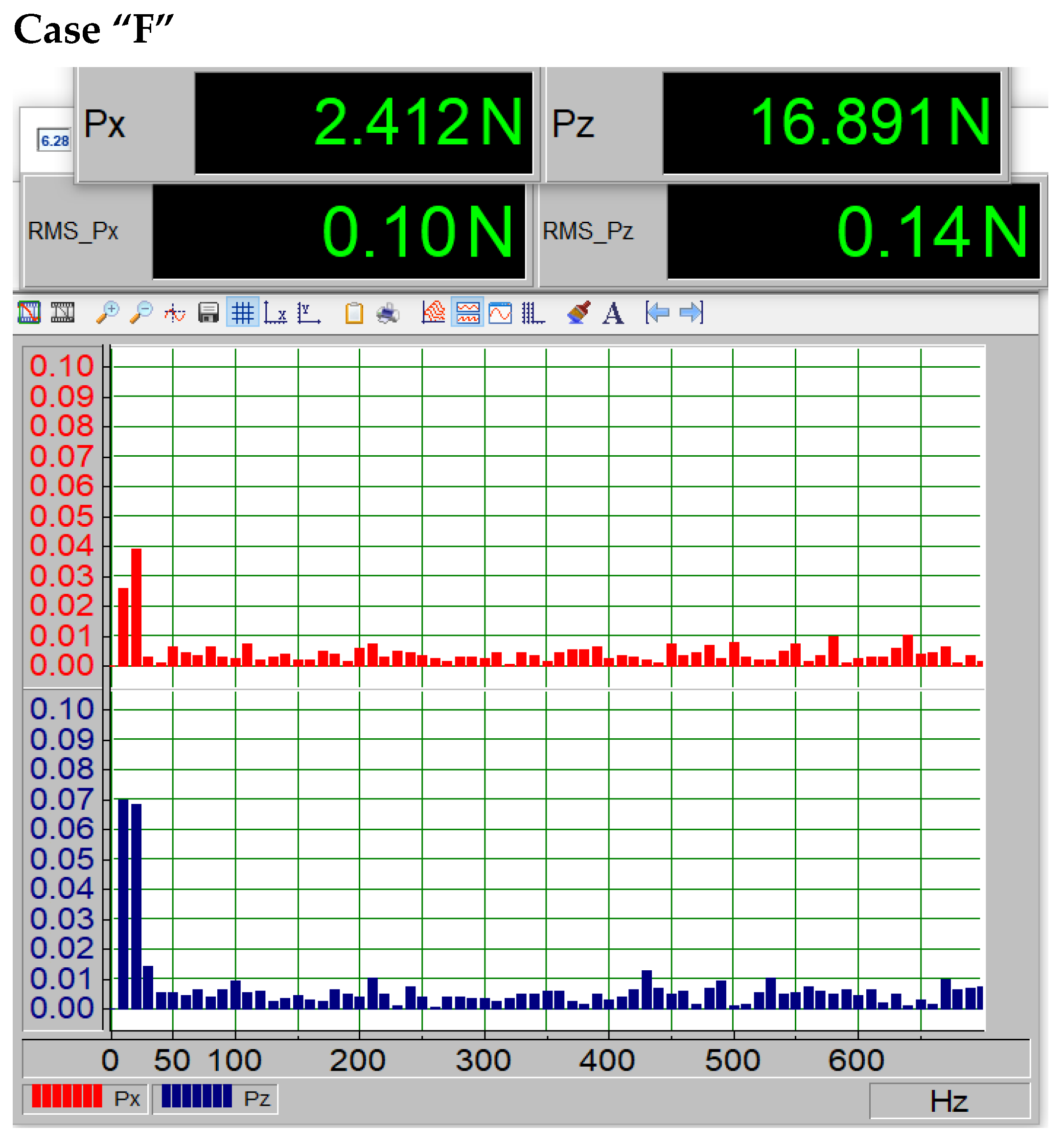
| Surface Type | RMS_Pz | Amplitude of the Dominant Frequency |
|---|---|---|
| H (smooth) | 0.14 | 0.07 |
| F (minor damage) | 0.14 | 0.07 |
| G (moderate) | 0.27 | 0.25 |
| I (severe damage) | 0.48 | 0.52 |
Disclaimer/Publisher’s Note: The statements, opinions and data contained in all publications are solely those of the individual author(s) and contributor(s) and not of MDPI and/or the editor(s). MDPI and/or the editor(s) disclaim responsibility for any injury to people or property resulting from any ideas, methods, instructions or products referred to in the content. |
© 2025 by the authors. Licensee MDPI, Basel, Switzerland. This article is an open access article distributed under the terms and conditions of the Creative Commons Attribution (CC BY) license (https://creativecommons.org/licenses/by/4.0/).
Share and Cite
Żyłka, W.; Majka, A.; Skała, P.; Szczerba, Z.; Cieniek, B.; Stefaniuk, I. Impact of Degraded Aviation Paints on the Aerodynamic Performance of Aircraft Skin. Materials 2025, 18, 2401. https://doi.org/10.3390/ma18102401
Żyłka W, Majka A, Skała P, Szczerba Z, Cieniek B, Stefaniuk I. Impact of Degraded Aviation Paints on the Aerodynamic Performance of Aircraft Skin. Materials. 2025; 18(10):2401. https://doi.org/10.3390/ma18102401
Chicago/Turabian StyleŻyłka, Wojciech, Andrzej Majka, Patrycja Skała, Zygmunt Szczerba, Bogumił Cieniek, and Ireneusz Stefaniuk. 2025. "Impact of Degraded Aviation Paints on the Aerodynamic Performance of Aircraft Skin" Materials 18, no. 10: 2401. https://doi.org/10.3390/ma18102401
APA StyleŻyłka, W., Majka, A., Skała, P., Szczerba, Z., Cieniek, B., & Stefaniuk, I. (2025). Impact of Degraded Aviation Paints on the Aerodynamic Performance of Aircraft Skin. Materials, 18(10), 2401. https://doi.org/10.3390/ma18102401