Abstract
This study developed a new way of designing choline chloride-modified MOF-based materials with advanced gas adsorption properties. To design better carbon capture materials, MIL-101 (Cr) was prepared using the hydrothermal method, and then was modified with different concentrations of choline chloride in a one-step method to enhance its CO2 adsorption capacity. The characterization and experimental results indicated that the modified ChCl-MIL-101(Cr) significantly enhanced the adsorption capacity for CO2. Specifically, the 0.075-ChCl-MIL-101(Cr) showed a 61.191% increase in adsorption capacity compared to that of the raw material. Moreover, the regenerated adsorption loss rate of the modified material was below 4%, proving the permanence of the material synthesis. Simulating isotherms using Langmuir and Freundlich equations revealed the non-uniformity of surface bonding.
1. Introduction
With the process of industrialization, the emission of greenhouse gases, primarily carbon dioxide (CO2), has caused global warming and seriously threatened the development of human society [1]. Moreover, the decrease in pH caused by carbon dioxide and the hazards brought about by carbon dioxide mineralization are also increasing rapidly [2,3]. CO2 capture technologies constitute an important approach to solving the above problems [4]. There are four application scenarios for CO2 capture: pre-combustion capture, oxygen-enriched combustion, post-combustion capture, and direct air capture. The corresponding CO2 concentrations for these scenarios are 15% to 60%, 75% to 90%, 4% to 15%, and 0.02% to 0.04%,respectively [5]. Currently, the absorption method is the most widely used decarbonization technology for high-concentration CO2 capture scenarios, with inorganic alkali or organic amine solution as the core material [6]. However, this technology requires high regeneration energy consumption and encounters prominent problems such as pipeline corrosion, resulting in high decarbonization costs [7,8,9]. In recent years, the adsorption method has been widely favored by virtue of its high overall stability and low regeneration energy consumption, especially in the field of low concentration (≤15%) CO2 capture, and it is considered part of a new generation of CO2 capture technology with great application prospects. The core of the adsorption method lies in developing adsorption materials with high adsorption capacity, high adsorption selectivity, and high stability [10,11,12].
In addition to the implementation of good environmental practices and eco-sustainable energy policies, environmental preservation can be also achieved through the drastic and rapid reduction of global greenhouse gas emissions via their capture. In particular, the effects CO2 could be mitigated through the use of the best scientific knowledge available in the development of effective technologies in carbon capture and storage (CCS) or utilization (CCU) [13,14,15]. At present, there are two main CO2 adsorption technologies: one is the chemical adsorption method, and the other is the physical adsorption method. The physical absorption method separates CO2 by taking advantage of the difference in the solubility of CO2 in the aqueous phase. The chemical absorption principle realizes the adsorption of CO2 through the acid–base neutralization of CO2. Commonly used adsorption materials currently include carbon based materials [16], zeolites [17], silica [18], MOFs [19], as well as other materials for porous adsorption. Among them, MOFs have high crystallinity, a high specific surface area, and adjustable pore structure, demonstrating considerable potential in the field of CO2 capture. MOFs possess advantages that other materials cannot achieve, such as a high surface area, the capability to physically adsorb hydrogen, and the separation and storage of CH4 and CO2 [20]. The MILs in MOFs have excellent stability, and each metal ion has a capped ligand. Employing highly coordinated amino groups for substitution, specific structures and even specific functions can be achieved through the design of raw material molecules [21,22].
Based on various factors such as the interaction force and mechanism between the material and the target pollutant [23], the structure of the material can be modified to synthesize MIL metal frameworks with suspended amino groups, showing stronger CO2 adsorption capacity, and can significantly improve the selective adsorption and capture capability of CO2. Zhang [24] synthesized MIL-101 (Cr) by using chromium nitrate (Cr(NO3)3·9(H2O)), terephthalic acid, and hydrofluoric acid. Its specific surface area reached 2846.69 m2·g−1, its pore volume was 2.45 cm3·g−1, and average pore size was 0.98 nm. Compared with other MIL-101 materials, its crystal structure and adsorption effect were the best. Additionally, Liang Fangfang found that it can adsorb CO2 at room temperature and pressure, with improved adsorption capacity and selectivity. MIL-101 (Cr) modified by ED can effectively adsorb greenhouse gas CO2 under mild conditions at room temperature and pressure. The modified material MIL-101-ED-0.18 has an adsorption capacity of 2.43 mmol·g−1 for CO2 at room temperature and pressure, an increase of 14.6% compared to that of before modification, which is higher than other similar materials. The modified material also has greatly improved gas adsorption selectivity, with its CO2/N2 selective separation coefficient increasing from 11 to 17, an increase of 55.6% compared to that of before modification. Chang [25] fabricated a novel bimetallic MIL-101 (Cr, Mg), and compared with loading a single metal material, the synergistic effect of the bimetallic material was shown to improve its CO2/N2 adsorption selectivity. The adsorption capacity and pore size of other MOF materials are shown in Table 1.

Table 1.
Comparison of CO2 adsorption capacity of different MIL materials.
Choline chloride is also widely used in carbon dioxide absorption applications [31]. Its low melting point solvent (ChCl EG-based DES) formed with ethylene glycol (EG) is a new type of ionic liquid, which has the advantages of low price, low viscosity, easy synthesis, and suitability for large-scale production [32]. However, it still cannot escape the disadvantages of low regeneration energy consumption and high corrosiveness, and ethylene glycol does not have alkaline groups, so its capability to absorb carbon dioxide is relatively weak. Giancarlo developed choline amino acid based ionic liquids ([Ch][His]ILs) using choline (quaternary ammonium cation) instead of imidazole cation, which are almost non-toxic and considered green chemicals [33]. Cheng [34] demonstrated the performance of choline amino acids in absorbing carbon dioxide. The results indicate that when the moisture content is 30%, the CO2 absorption increases continuously with increasing pressure. Although the absorption of CO2 by a single choline amino acid ionic liquid is hindered by viscosity, its aqueous solution has a good absorption effect [35,36].
Porous materials can be used for the separation and adsorption of gases due to their adsorption principle being physical adsorption and their high porosity and huge specific surface area, as well as their low adsorption kinetics and selectivity [37]. They must, therefore, be changed and activated. The use of active functional groups for surface modification is regarded as one of the most common and effective methods [13]. Carbon dioxide is an acidic gas, and based on physical adsorption, the introduction of basic amine groups can be used to incorporate chemical adsorption, which can significantly enhance the material’s adsorption performance for carbon dioxide [38,39].
However, despite the continuous progress in CO2 capture technology, there are still some critical issues that remain unresolved. For instance, most existing adsorption materials face challenges such as high cost, low adsorption capacity under practical conditions, and poor long-term stability. Additionally, the balance between the efficiency of carbon capture and the energy consumption during the adsorption-desorption process has not been well-addressed. These problems severely limit the large-scale application of carbon capture technology. Therefore, in the context of these persistent challenges in the field of CO2 capture science, this study aims to develop an efficient and cost-effective solution.
The impact of choline chloride concentration on material structure and CO2 adsorption performance is thoroughly examined in this study, and the CO2 adsorption behavior of composite materials is analyzed using adsorption isotherm equations. The results show that with an increase in choline chloride concentration, the CO2 adsorption trend displayed a volcano pattern, and the CO2 adsorption of 0.075-ChCl-MIL-101 (Cr) was the best. MIL-101 (Cr) has a unique pore cage structure that makes it capable of efficiently adsorbing CO2. A multilayer porous MOF is created when the composite material and choline chloride mix through coordination and hydrogen bonding. Both the chemical and physical characteristics of the materials are monitored using a variety of characterization techniques. The composite material’s capacity for adsorbing carbon dioxide is determined, and a comprehensive examination of the adsorption process mechanism is conducted.
2. Materials and Methods
2.1. Materials and Equipment
Table 2.
Summary of materials.
Table 3.
Summary of experimental equipment.
2.2. Material Preparation
2.2.1. Preparation of MIL-101 (Cr)
A hydrothermal synthesis method was employed, where 2.4 g of Cr(NO3)3·9H2O was dissolved in 28.6 mL of deionized water. Then, 0.996 g of H2BDC was added after thorough stirring, and 0.26 mL of 40% HF was dripped in while stirring. The mixture was then subjected to ultrasonic agitation for 30 min before being transferred to a reaction vessel. The reaction was carried out at 220 °C for 8 h. After cooling, the green product was obtained and subjected to solid-liquid separation using a centrifuge. It was then washed repeatedly with DMF and anhydrous ethanol until the liquid’s color no longer changed. After filtration, the product was placed in an 80 °C oven for drying for 8 h. Finally, the green product was stored in a sealed bag and labeled as MIL-101 (Cr) [40].
2.2.2. Preparation of n-ChCl-MIL-101 (Cr)
N-ChCl-MIL-101 (Cr) was modified using a one-step method. Firstly, 0.996 g of H2BDC was dissolved in water, and different concentrations of ChCl were added dropwise for the reaction. Then, 2.4 g of Cr(NO3)3·9H2O was added, and the mixture was shaken in an ultrasonic oscillator for half an hour. Meanwhile, 0.26 mL of 40% concentration HF was added dropwise while stirring. The mixture was then added to a reaction vessel and reacted at 220 °C for 8 h. After cooling, the green product was obtained and subjected to solid–liquid separation using a centrifuge. Then, DMF and anhydrous ethanol were washed back and forth until the liquid color did not change anymore. After filtration, the product was dried in an 80 °C oven for 8 h. Finally, the green product was placed in a sealed bag and labeled with n-ChCl-MIL-101 (Cr) for storage (where n represents the concentration of ChCl).
2.3. Characterization of Materials
2.3.1. XRD Characterization and Testing Conditions
X-ray diffraction (XRD) was used to determine the crystal structures of the different materials. Phase analysis was conducted on the adsorbent samples, and their diffraction patterns were analyzed to determine the peak positions, thereby understanding the composition, internal atomic or molecular structure, and morphology of the samples. The testing conditions for the X-ray diffractometer were as follows: Cu target, Kα radiation (λ = 0.15406 nm), tube voltage and current of 40 kV and 40 mA, respectively, with a scanning speed of 0.5°/min and a 2θ scanning range of 5° to 80° [41].
2.3.2. SEM Characterization and Testing Conditions
Scanning electron microscopy (SEM) was used to characterize the morphology and size of the prepared adsorbents. Owing to the advantage of dispersing particles for clearer SEM characterization results, the particle dispersion process needed to be carried out first. The prepared samples were dissolved in anhydrous ethanol, ultrasonication was started, and the sample was dropped onto a conductive copper plate. Finally, we performed characterization after gold spraying treatment to observe the morphological characteristics of different adsorbents.
2.3.3. N2 Adsorption Instrument Characterization and Testing Conditions
The parameter employed for studying the adsorption performance of porous materials is the adsorption/desorption isotherm [42]. For different porous materials, their pore structure and pore size are different, so irreversible adsorption and desorption processes may occur. On the adsorption/desorption isotherm line, it is manifested that the adsorption and adsorption isotherms cannot completely coincide, resulting in hysteresis phenomenon, that is, a hysteresis loop [43]. We can observe the internal pore structure of porous materials from the shape of adsorption/desorption isotherms, and the position and shape of hysteresis loops.
This experiment employed an N2 adsorption instrument to measure the adsorption/desorption isotherms of different metal-based adsorbents for N2 at 77 K liquid nitrogen temperature. Prior to testing, the samples were subjected to degassing pretreatment at 100 °C for 6 h, from which the specific surface area, pore volume, and pore size of the materials were calculated.
2.3.4. FT-IR Characterization and Testing Conditions
FT-IR can be used for the analysis and identification of substance molecules, as well as for the analysis of molecular structures and chemical bonds. A Fourier transform infrared spectrometer was employed to perform sample infrared analysis. After drying and removing water from the sample, it was mixed with potassium bromide and pressed into tablets. After being secured inside the sample cell, the infrared spectrum was captured. A wavenumber range of 4000 cm−1~500 cm−1 was observed.
2.3.5. ThermogravimetricCharacterization and Testing Conditions
We performed thermal stability analysis on the material using a thermogravimetric analyzer, recorded the relationship between heat changes and temperature, and increased the temperature to 700 °C at a heating rate of 5 °C/min.
2.3.6. EDS Characterization and Testing Conditions
The incident electron beam was adopted to excite the primary X-rays of the sample material, and the varying energy and wavelengths of the distinctive X-rays were examined to determine the sorts of elements. The composition of each component in the sample material was determined by comparing the content of five elements: C, O, Cr, Cl, and N [13].
2.4. Adsorption Experiment
2.4.1. CO2 Adsorption Experiment
A BET instrument was used to investigate the samples’ CO2 adsorption capability. Prior to the test, for the degassing procedure, the samples were placed into a sample tube at a designated weight (200 mg).
The samples were degassed in N2 at 393 K for 6 h to remove moisture and dust, and to desorb impurities such as CO2 adsorbed in the sample air, ultimately achieving a pure state. The test results included CO2 adsorption isotherms at 298 K and an external pressure range ranging from 0.7~100 kPa. The equation of state was used to fit with the adsorption isotherm.
2.4.2. CO2 Adsorption Penetration Experimental Apparatus
The experimental setup for MIL-101 adsorption of low concentration CO2 is shown in Figure 1. The experimental setup mainly consisted of four systems, namely, a gas supply system, flow detection system, fixed bed adsorption system, and data acquisition system. The gas supply system consisted of a CO2 cylinder, an N2 cylinder, a pressure gauge, and a pressure reducing valve. N2 was used for the purging pretreatment of the experimental device, mixing CO2 gas and N2 gas. Both gases were controlled by a rotor flowmeter to regulate their flow rate, and then corrected by a soap bubble flowmeter. The fixed bed adsorption system was mainly used for adsorption experiments. The fixed bed size was a high-temperature resistant quartz glass tube with an inner diameter of 5 mm, an outer diameter of 8 mm, and a length of 120 mm. The adsorbent was filled inside the tube. The data acquisition system consisted of a gas sampling port and a CO2 gas analyzer, which measured the concentration of CO2.
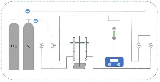
Figure 1.
Flow chart of CO2 adsorption penetration experiment device.
2.4.3. Adsorption Penetration Experiment Process
The specific experimental process for adsorption penetration was as follows:
- Before starting the adsorption experiment, according to the experimental requirements, 1 g of adsorbent was placed in a quartz glass tube and fixed at both ends with cotton balls.
- The entire pipeline was blown with N2. The adsorption experiment was started once the CO2 gas analyzer could not detect any CO2 concentration.
- The two valves of the quartz glass tube were closed, and CO2 gas and N2 gas were introduced. Preliminary calibration was performed through a glass rotor flowmeter, and a soap bubble flowmeter was leveraged for secondary calibration. The flow ratio of CO2 to N2 was 15:85; that is, the flow rate of CO2 was 6 mL/min, and the flow rate of N2 was 34 mL/min.
- After completing the calibration, the two valves that entered the glass quartz tube were opened, and the two valves that entered the soap bubble flowmeter were closed. The fixed bed adsorption experiment was started and the CO2 concentration obtained from the adsorption reaction online was monitored in order to obtain the CO2 concentration at different times. When the outlet CO2 concentration was detected to be the same as that in the inlet mixed gas, monitoring ceased.
- The device and the entire gas path were closed, the adsorption experiment was ended, and the adsorption penetration curve was drawn.
2.4.4. Adsorption–Desorption Cycle Experimental Process
To comprehend the stability of adsorbents, it is crucial to research the adsorption desorption cycle. The adsorbent was placed under vacuum conditions at 120 °C for 6 h and the adsorption process was repeated four times. The stability of the adsorbent was determined by comparing its adsorption capacity.
2.4.5. Adsorption Isotherms and Isotherm Equations
The adsorption isotherm equation provides a mathematical description of the adsorption isotherm. The common adsorption isotherm equations include Langmuir equation [44], Freundlich equation [45], Temkin equation [46], Henry equation [47], etc. The Langmuir equation and Freundlich equation are applicable to both physical and chemical adsorption. These two adsorption equations are chosen to characterize the functional relationship in the adsorption isotherm based on the properties of the materials reported in the literature.
- (1)
- Langmuir equation
The Langmuir equation is one of the most famous and widely used adsorption isotherm equations [48], which well describes the adsorption isotherms in the low and medium pressure ranges. When the adsorbate partial pressure in the gas is high and close to the saturated vapor pressure, the equation deviates. This is because the adsorbate at this time can condense in fine capillaries, and the assumption of monolayer adsorption is not valid [49]. The linear expression is as follows:
qe: The equilibrium adsorption capacity of the adsorbent,
qm: The maximum adsorption capacity of the adsorbent,
p: CO2 partial pressure,
KL: Langmuir constant.
- (2)
- Freundlich equation
The Freundlich isotherm model is the most widely used model for non-ideal adsorption and multilayer adsorption on heterogeneous surfaces [50]. The Freundlich equation is mainly used for studying the adsorption isotherms of porous solids on adsorbates, which is of great significance for analyzing and predicting adsorption processes. The value of n is related to the surface inhomogeneity of the adsorbent and the energy change in the adsorption process. The larger the value of n, the closer the adsorption process is to monolayer adsorption, and the more uniform the adsorbent surface is. On the contrary, the more significant the surface inhomogeneity of the adsorbent, the more obvious the characteristics of multilayer adsorption. Its mathematical expression is:
n: The degree of heterogeneity in the adsorption process,
KF: Freundlich constant.
3. Results and Discussions
3.1. Feature Analysis
3.1.1. XRD Analysis
The X-ray diffractometers of adsorbents MIL-101 (Cr), 0.075-ChCl-MIL-101 (Cr), 0.1-ChCl-MIL-101 (Cr), and 0.125-ChCl-MIL-101 (Cr) are shown in the Figure 2. In contrast to MIL-101’s conventional diffraction peaks (Cr), the diffraction peaks of MIL-101 (Cr) at 2θ = 8.4°, 9.04°, and 16.48° confirm the reconstruction of MIL-101 (Cr) [51]. It can be seen that the diffraction peak of MIL-101 (Cr) is relatively sharp and the intensity is high, indicating that the crystal structure of MIL-101 (Cr) is relatively regular. A regular crystal structure usually means that the material has a regular arrangement of pores and adsorption sites, which is conducive to the adsorption of adsorbent molecules. After modification, such as 0.075-ChCl-MIL-101 (Cr), 0.1-ChCl-MIL-101 (Cr), and 0.125-ChCl-MIL-101 (Cr), the shape and intensity of the diffraction peak changed. This indicates that the modification process may change the crystal structure of the material, and then affect the distribution and properties of the adsorption sites. Through comparison of the diffraction peak intensity, it can be found that the modified positions are mainly concentrated at 8.4° and 16.8°.
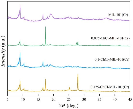
Figure 2.
XRD images of MIL-101 (Cr), 0.075-ChCl-MIL-101 (Cr), 0.1-ChCl-MIL-101 (Cr), and 0.125-ChCl-MIL-101 (Cr).
3.1.2. SEM Analysis
The scanning electron microscopy images of adsorbents MIL-101 (Cr), 0.075-ChCl-MIL-101 (Cr), 0.1-ChCl-MIL-101 (Cr), and 0.125-ChCl-MIL-101 (Cr) are shown in the figure. In Figure 3a, The octahedral structure of MIL-101 (Cr) is regular, which is consistent with the findings published in the literature [52]. From Figure 3b, it can be seen that after the combination of the two, the skeleton structure of MIL-101 (Cr) begins to change from smooth to rough because ChCl adheres to the surface of MIL-101 (Cr). In accordance with the findings of the FT-IR investigation, the larger 0.075-ChCl-MIL-101 (Cr) can also be seen for its crystal shape from its interior pores. Furthermore, as ChCl continues to adhere, the uniform channels inside MIL-101 (Cr) begin to fold and bend, which may be due to ChCl filling the MIL-101 (Cr) channels, slightly altering the surface morphology of MIL-101 (Cr). Comparing Figure 4b–d, it can be seen that after ChCl loading, the skeleton structure of MIL-101 (Cr) becomes rougher and more defective, and the internal channel curvature deepens. This suggests that MIL-101 (Cr)’s internal and surface channel structures are affected by ChCl loading. Concurrently, MIL-101 (Cr)’s morphology experiences aggregation and deformation, indicating that ChCl was successfully loaded into MIL-101 (Cr). As the loading amount of ChCl increases, the MIL-101 (Cr) structure becomes rougher and the distortion deepens, indicating that more ChCl molecules are filled in the pores of the MIL-101 (Cr) skeleton.
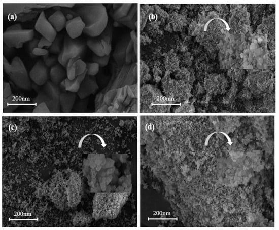
Figure 3.
SEM images of (a) MIL-101 (Cr), (b) 0.075-ChCl-MIL-101 (Cr), (c) 0.1-ChCl-MIL-101 (Cr), and (d) 0.125-ChCl-MIL-101 (Cr).
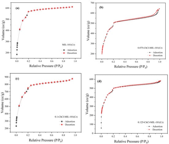
Figure 4.
N2 adsorption instrument image of (a) MIL-101 (Cr), (b) 0.075-ChCl-MIL-101 (Cr), (c) 0.1-ChCl-MIL-101 (Cr), and (d) 0.125-ChCl-MIL-101 (Cr).
3.1.3. N2 Adsorption Instrument Analysis
The adsorption breakthrough curves of adsorbents MIL-101 (Cr), 0.075-ChCl-MIL-101 (Cr), 0.1-ChCl-MIL-101 (Cr), and 0.125-ChCl-MIL-101 (Cr) are shown in Figure 4. From the isothermal trend lines, MIL-101 (Cr) adsorbents all belong to Class I isotherms, while 0.075-ChCl-MIL-101 (Cr), 0.1-ChCl-MIL-101 (Cr), and 0.125-ChCl-MIL-101 (Cr) belong to Class IV isotherms [53]. The N2 adsorption/desorption isotherms of these four different adsorbents appear similar but have significant differences. From Figure 4a, it can be seen that the adsorption–desorption curves almost overlap, indicating that the adsorption/desorption process did not produce a hysteresis loop. This means that the pore structure within the adsorbent is relatively small and contains a large number of microporous structures, with an adsorption capacity of 610 cc/g. From Figure 4b, it can be seen that there is a turning point around P/P0 = 0.2, which is the first steep point of the isotherm and represents the saturated adsorption capacity of its single molecule, indicating that its adsorption capacity is complete. However, the adsorption capacity still exceeds that of MIL-101 (Cr) before modification, reaching 641 cc/g. From Figure 4c, it can be seen that although 0.1 mol/L choline chloride modification has the best adsorption and desorption effect on nitrogen gas, reaching 830 cc/g, a narrow hysteresis loop appears around P/P0 = 0.18, indicating the presence of a large number of mesopores and relatively few micropores in the 0.1-ChCl-MIL-101 (Cr) sample. From Figure 4d, it is evident that the adsorption–desorption curves are essentially overlapping, with only a narrow hysteresis loop observed at P/P0 = 0.17 and P/P0 = 0.97, which represents a significant amount of mesopores, while the micropores are comparatively less. The adsorption capacity is 582 cc/g.
The pore size distribution for MIL-101 (Cr), 0.075-ChCl-MIL-101 (Cr), 0.1-ChCl-MIL-101 (Cr), and 0.125-ChCl-MIL-101 (Cr) is shown in Figure 5. The data analysis of the specific surface area and porosity (BET) of different adsorbents is shown in Table 4. As can be seen from the figure, for MIL-101(Cr), within the pore size range of 0–10 nm, the pore volume fluctuates significantly with multiple peaks, indicating that this material has various pore structures with different pore sizes in the small-pore-size region. As the pore size further increases, the pore volume gradually decreases, and when the pore size is greater than 30 nm, the pore volume approaches zero, suggesting that large-sized pores account for a relatively small proportion in this material. The overall trend of 0.075-ChCl-MIL-101(Cr) is similar to that of MIL-101(Cr), but within the 0–10 nm range, the variation trend and specific values of the pore volume differ from those of MIL-101(Cr). The peak positions and magnitudes are slightly different, which means that after introducing 0.075 mol/L of ChCl, the pore structure of the material has changed to some extent in the small-pore-size region, leading to an adjustment in the pore volume distribution of different pore sizes. For 0.1-ChCl-MIL-101(Cr), within the 0–10 nm pore size range, the variation amplitude of the pore volume is relatively large, and the peaks are distinct.
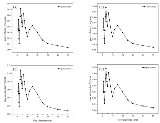
Figure 5.
Pore size distribution image for (a) MIL-101 (Cr), (b) 0.075-ChCl-MIL-101 (Cr), (c) 0.1-ChCl-MIL-101 (Cr), and (d) 0.125-ChCl-MIL-101 (Cr).
Table 4.
BET data analysis of different adsorbents.
Compared with the former two, the values of the pore volume at certain pore sizes are different, indicating that as the ChCl content increases to 0.1 mol/L, the influence on the pore structure of the material is further intensified, altering the crystal growth or assembly process of the material and thus affecting the pore size distribution. For 0.125-ChCl-MIL-101(Cr), the pore volume also fluctuates significantly in the 0–10 nm region. However, compared with the other three materials, the details of the pore volume distribution are different. As the ChCl content increases to 0.125 mol/L, the pore structure of the material continues to be modified, influencing the pore formation mechanism of the material at the microscopic level and endowing the pore size distribution with unique characteristics.
3.1.4. FT-IR Analysis
The infrared spectra of adsorbents MIL-101 (Cr), 0.075-ChCl-MIL-101 (Cr), 0.1-ChCl-MIL-101 (Cr), and 0.125-ChCl-MIL-101 (Cr) are shown in Figure 6. The Cr-O vibrational absorption peak appeared at 586 cm−1, the C-H vibrational peaks adjacent to the benzene ring appeared at 740 cm−1 and 827 cm−1, an aromatic acid was confirmed at 1279 cm−1, the C=O vibrational peak on the symmetrical carboxylate group was located at 1400 cm−1, 1549.6 cm−1 illustrated to the characteristic peak of the benzene ring, and 3409 cm−1 represented the characteristic peak of the carboxylate. This indicates that MIL-101 (Cr) was successfully synthesized, and after adding different concentrations of ChCl, the characteristic peaks at 3000–3400 cm−1 showed large pure peaks, indicating the introduction of a large number of hydroxyl groups. This result further proves the successful modification of ChCl.
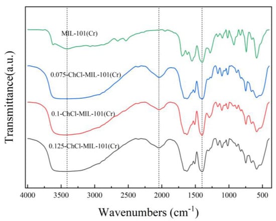
Figure 6.
FT-IR images of MIL-101 (Cr), 0.075-ChCl-MIL-101 (Cr), 0.1-ChCl-MIL-101 (Cr), and 0.125-ChCl-MIL-101 (Cr).
3.1.5. Thermogravimetric Analysis
The thermogravimetric curves of adsorbents MIL-101 (Cr), 0.075-ChCl-MIL-101 (Cr), 0.1-ChCl-MIL-101 (Cr), and 0.125-ChCl-MIL-101 (Cr) are shown in Figure 7. The thermogravimetric analysis of MIL-101 (Cr) mainly consisted of three stages. The escape of water molecules from the larger pore cages (about 34 Å) of the MIL-101 (Cr) structure was the cause of the modest weight loss that occurred before 100 °C. The solvent molecules escaping from the medium pore cage (about 29 Å) caused the weight loss at 100–200 °C; above 200 °C, the MIL-101 (Cr) structure disintegrated and the material lost weight quickly. Owing to the removal of hydroxyl groups from the skeleton, the structure began to collapse [54]. Consequently, MIL-101 (Cr) sustained its structural integrity at an internal temperature of about 200 °C while experiencing a 71.71% mass loss.
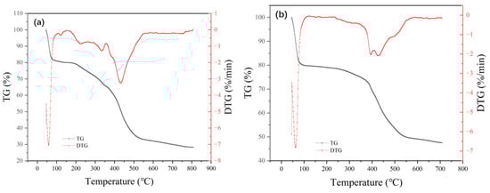
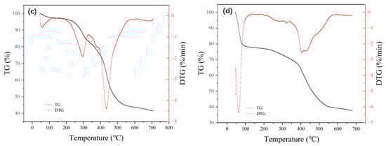
Figure 7.
Thermogravimetric images of (a) MIL-101 (Cr), (b) 0.075-ChCl-MIL-101 (Cr), (c) 0.1-ChCl-MIL-101 (Cr), and (d) 0.125-ChCl-MIL-101 (Cr).
The comparison of the residual weights of four different materials is shown in Figure 8. After modification with choline chloride, there was a significant enhancement in both thermal stability and residual mass. At temperatures close to 400 °C, the 0.075-ChCl-MIL-101(Cr) can maintain structural integrity, with a mass loss of 52.49%. Compared to the original material, the residual mass increased by 59.54%. However, as the concentration of choline chloride increases, the thermal stability and residual mass start to decline gradually. This is attributed to the decomposition of choline chloride at high temperatures, leading to greater mass loss at higher concentrations, but still surpassing that of the original material.
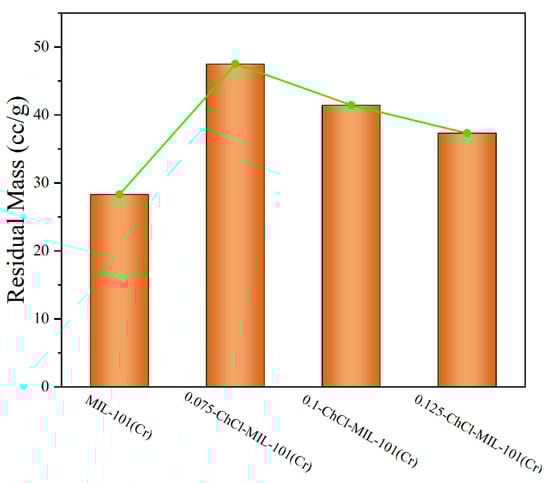
Figure 8.
Comparison of residual amounts of each sample.
3.1.6. EDS Analysis
The EDS of adsorbents MIL-101 (Cr), 0.075-ChCl-MIL-101 (Cr), 0.1-ChCl-MIL-101 (Cr), and 0.125-ChCl-MIL-101 (Cr) are shown in Figure 9. The data analysis of the elemental composition of different adsorbents is shown in Table 5. During the experiment, some material may be lost from the final sample material after processing. The true composition and proportion of the material can be established by utilizing energy spectrum analysis to examine the kinds and specific gravity of surface distinctive components. The Cr and C elements of a typical MIL-101 (Cr) structure are depicted in Figure 9a. Cr and Cl can be observed in Figure 9b–d, showing a successful composite of the two materials, in line with the findings of the SEM. In addition, based on the content in the table, it can be seen that with an increase in ChCl impregnation amount, the findings of the FT-IR, thermal stability, and SEM analyses are incompatible with the growing quantity of ChCl that is actually loaded into the sample.
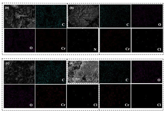
Figure 9.
EDS image of (a) MIL-101 (Cr), (b) 0.075-ChCl-MIL-101 (Cr), (c) 0.1-ChCl-MIL-101 (Cr), and (d) 0.125-ChCl-MIL-101 (Cr).
Table 5.
Elemental composition data analysis of different adsorbents.
3.2. Adsorption Experiment
3.2.1. CO2 Adsorption Experiment
The adsorption properties of n-ChCl-MIL-101 (Cr) and MIL-101 (Cr) modified with different concentrations of choline chloride are shown in the Figure 10. From the figure, it is evident that in the same experimental circumstances, the modification of MIL-101 (Cr) and choline chloride at different concentrations is slightly different. The adsorption capacities of adsorbents MIL-101 (Cr), 0.075-ChCl-MIL-101 (Cr), 0.1-ChCl-MIL-101 (Cr), and 0.125-ChCl-MIL-101 (Cr) are 17.8972 cc/g, 28.8487 cc/g, 20.6239 cc/g, and 27.4263 cc/g, respectively. The comparison of the carbon dioxide adsorption experiments of each sample is shown in Figure 11. The maximum CO2 adsorption capacity of choline chloride modified MIL-101 (Cr) at different concentrations is Q0.075 > Q0.125 > Q0.1 > QMIL-101 (Cr), and the carbon dioxide adsorption capacity increases by 61.191%, 15.235%, 53.243% after modification. It can be inferred that the adsorption property is proportional to the pore size, and it can be inferred that its adsorption performance exhibits a volcano-shaped relationship with the adsorption capacity for carbon dioxide, reaching the maximum adsorption capacity at a concentration of 0.075 mol/L.
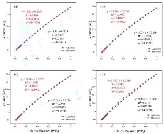
Figure 10.
CO2 adsorption experiment image for (a) MIL-101 (Cr), (b) 0.075-ChCl-MIL-101 (Cr), (c) 0.1-ChCl-MIL-101 (Cr), and (d) 0.125-ChCl-MIL-101 (Cr).
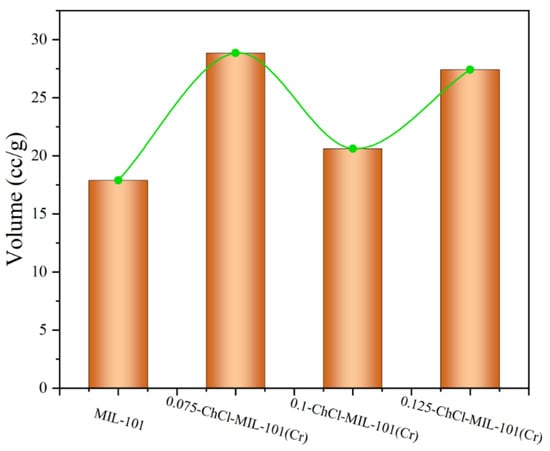
Figure 11.
Comparison of CO2 adsorption experiment of each sample.
3.2.2. Analysis of Adsorption Breakthrough Curve
The adsorption breakthrough curves of adsorbents MIL-101 (Cr), 0.075-ChCl-MIL-101 (Cr), 0.1-ChCl-MIL-101 (Cr), and 0.125-ChCl-MIL-101 (Cr) are shown in Figure 12. From the figure, it is apparent that the CO2 adsorption breakthrough curves of the adsorbent materials modified at different concentrations are quite similar, each shifting from a steep to a more gradual slope. The breakthrough time of MIL-101 (Cr) is about 12–17 min, the breakthrough time of 0.075-ChCl-MIL-101 (Cr) is about 24–31 min, the breakthrough time of 0.1-ChCl-MIL-101 (Cr) is about 16–22 min, and the breakthrough time of 0.125-ChCl-MIL-101 (Cr) is about 22–27 min. Among them, the breakthrough time of choline chloride modification with 0.075 mol/L is the longest, indicating that its concentration choline chloride modification has the best adsorption effect on carbon dioxide.
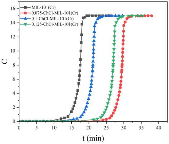
Figure 12.
Comparison of CO2 adsorption breakthrough curve of each sample.
3.2.3. Adsorption Desorption Cycle Experimental Process
The adsorption desorption cycles of the adsorbents MIL-101 (Cr), 0.075-ChCl-MIL-101 (Cr), 0.1-ChCl-MIL-101 (Cr), and 0.125-ChCl-MIL-101 (Cr) are shown in the Figure 13. The data demonstrate no material loss or degradation during the recycling process, with the largest variation in adsorption capacity being less than 4%. This demonstrates the synthetic material’s durability.
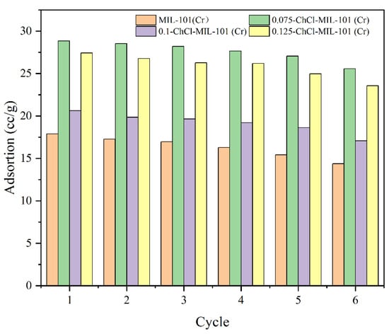
Figure 13.
Four cycles of CO2 uptake on the samples at 298 K.
3.2.4. Adsorption Isotherms and Isotherm Equations
The adsorption of CO2 by adsorbent 0.075-ChCl-MIL-101 (Cr) at different temperatures is shown in Figure 14. The findings show that the temperature has an inverse relationship with the equilibrium amount of carbon dioxide adsorption. This is because exothermic adsorption is the norm [55]. Therefore, raising the temperature will decrease adsorption as long as the adsorption equilibrium is reached. It was discovered that both the Langmuir and Freundlich fitting results of CO2 isotherms may accurately fit the isotherm data. However, it was also discovered that the Freundlich fitting effect outperforms Langmuir for materials treated with choline chloride, suggesting that the current situation cannot be adequately described by the assumption of monolayer adsorption. In multilayer adsorption, the first layer of adsorbent molecules binds to the active sites on the surface of the adsorbent, and the adsorption energy of these active sites is different due to the surface heterogeneity. As the adsorption proceeds, the molecules of the subsequent adsorption layer interact not only with the adsorbent surface, but also with the adsorbed molecules. Adsorbents have the capability to adsorb gas molecules in layers. This suggests that surface binding in adsorption behavior is not uniform. Stated differently, there is an unequal distribution of adsorption energy on the material’s surface. This suggests that the composite material was effectively loaded with choline chloride, hence augmenting the chemical adsorption force within the material.
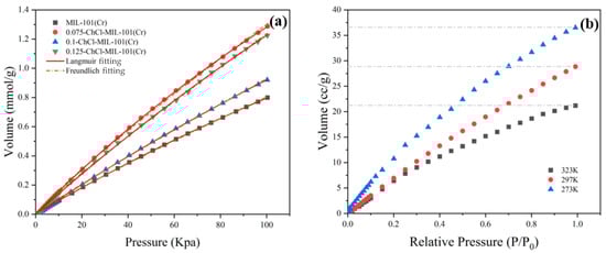
Figure 14.
CO2 adsorption isotherms: (a) Under the environment of 298 K (b) 0.075-ChCl-MIL-101 (Cr) under the environments of 273 K, 297 K, and 323 K.
The isothermal constants determined using nonlinear fitting of equilibrium data are summarized in Table 6. The temperature and characteristics of the adsorbent and adsorbate are connected to the Langmuir equilibrium constant (KL), whose value increases with the adsorbent’s adsorption performance [56]. After loading choline chloride, the chemical composition of KL increased, indicating that its adsorption performance was improved, and its value reflects the difficulty of adsorption behavior [57]. Based on the actual experimental data, the highest adsorption capacity among different choline chloride modifications is 0.075-ChCl-MIL-101 (Cr).
Table 6.
Langmuir and Freundlich constants of CO2 adsorption on samples at 298 K.
3.2.5. Analysis of CO2/N2 Adsorption Selectivity
The CO2/N2 Adsorption Selectivity of the adsorbents MIL-101 (Cr), 0.075-ChCl-MIL-101 (Cr), 0.1-ChCl-MIL-101 (Cr), and 0.125-ChCl-MIL-101 (Cr) are shown in the Figure 15. From the perspective of adsorption kinetics, as the concentration of carbon dioxide in the mixed gas decreases, the adsorption breakthrough times of the four adsorption materials all show a gradually increasing trend. Specifically, the adsorption breakthrough time of 0.04-[Ch][Phe]-MIL-101(Cr) is extended by approximately 4 min, that of 0.06-[Ch][Phe]-MIL-101(Cr) is extended by about 5 min, and that of 0.08-[Ch][Phe]-MIL-101(Cr) is extended by around 6 min. This phenomenon indicates that a lower carbon dioxide concentration slows down the diffusion rate of gas molecules within the pore channels of the adsorbent and reduces the effective collision frequency with the adsorption active sites, thus delaying the process of adsorption saturation and leading to an increase in the adsorption breakthrough time.
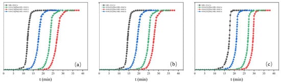
Figure 15.
Adsorption breakthrough curves at different concentrations: (a) CO2:N2 = 0.12:0.88 (b) CO2:N2 = 0.09:0.91 (c) CO2:N2 = 0.06:0.94.
Moreover, although the adsorption breakthrough times of the four materials all increase with the decrease in concentration, the increment gradually decreases. This shows that under low-concentration conditions, the adsorption selectivity of the adsorbent for carbon dioxide does not change in a simple linear manner, but there is a certain concentration threshold effect. When the carbon dioxide concentration decreases to a certain extent, the ability of the adsorbent to recognize and selectively adsorb carbon dioxide molecules can still be maintained at a relatively high level, causing the increase in the adsorption breakthrough time to slow down. This characteristic proves that these four materials still possess high CO2/N2 adsorption selectivity in an environment with a low carbon dioxide concentration. The underlying mechanism may stem from the special pore-channel structure and surface chemical properties of the adsorbent, which can preferentially recognize and adsorb carbon dioxide molecules, enabling effective separation of carbon dioxide from nitrogen even in a complex mixed-gas system with a low carbon dioxide content.
3.3. Analysis of the Mechanism of MIL-101 (Cr) Modified by Choline Chloride
The modification of MIL-101(Cr) with choline chloride enhances the carbon dioxide adsorption performance. The mechanism mainly involves aspects such as changes in the microstructure, alterations in the surface properties, and enhancement of the chemical interactions.
3.3.1. The Change in Microstructure Promotes Adsorption
During the modification process, choline chloride interacts with the MIL-101 (Cr) framework through weak interactions such as hydrogen bonds and van der Waals forces, inducing the rearrangement of the framework structure and increasing the pore volume. This reduces the mass transfer resistance of carbon dioxide molecules within the material, allowing them to diffuse more rapidly to the adsorption active sites and accelerating the adsorption kinetic process. For example, in experiments, the change in the adsorption breakthrough time of the modified material reflects this advantage. The breakthrough time of 0.075-ChCl-MIL-101 (Cr) is prolonged, indicating that it can adsorb more carbon dioxide under the same conditions.
3.3.2. Generation of Active Sites
Some functional groups in choline chloride, such as hydroxyl (-OH) and amino (-NH2) groups, will interact with the metal sites or organic ligands in MIL-101 (Cr), generating new active sites on the material surface or within the pores. These active sites can undergo chemical reactions with carbon dioxide molecules to form chemical bonds or chemisorption complexes. Hydroxyl can react with carbon dioxide through an acid–base neutralization reaction to form bicarbonate ions, etc., thus achieving the chemisorption of carbon dioxide.
3.3.3. Change in Electron Cloud Density
The presence of choline chloride can alter the electron cloud density around the metal ions in MIL-101 (Cr). For the Cr ions in MIL-101 (Cr), the change in electron cloud density affects their coordination ability with carbon dioxide molecules. The oxygen atoms in carbon dioxide molecules have lone pairs of electrons and can form coordination bonds with metal ions. After modification with choline chloride, the change in the electron cloud density around Cr ions enhances their coordination with carbon dioxide molecules, making it easier for carbon dioxide to be adsorbed and stabilized on the surface of the adsorbent.
4. Conclusions
This study employs the hydrothermal method to prepare MIL-101 (Cr), modifies the composite material using a one-step process, and effectively packs various choline chloride concentrations to produce a novel kind of carbon capture material. Choline chloride is added to the composite material, increasing its pore volume and decreasing its mass transfer resistance, accelerating the adsorption of CO2. MIL-101 has a more advantageous adsorption behavior due to its unique pore cage structure. A specific concentration of choline chloride added to composite materials allows them to keep their crystal structure. However, as the load increases, molecules fill the pores, reducing the material’s specific surface area and pore size to differing degrees.
The CO2 adsorption isotherm of the loaded material is more closely fitted by the Freundlich equation than by the Langmuir equation, suggesting that the adsorption behavior of materials treated with choline chloride on irregular surfaces is more consistent with multi-layer non-ideal adsorption behavior. The introduction of choline chloride enhances the sample’s adsorption capacity for CO2. The most effective adsorption effect on CO2 is shown by the composite material at a concentration of 0.075 mol/L. Under the conditions of 293 K and 100 kPa, a saturation adsorption capacity of 28.8487 cc/g is achieved, turning it into a carbon dioxide adsorbent with a wide range of potential uses. Since adsorption is an exothermic process, an increase in temperature causes a decrease in the adsorption capacity of the material. In conclusion, this study offers us a fresh approach to combination strategies.
The research findings of this study have significant practical implications at present, providing a new material option for the optimization of carbon capture technologies in the industrial field. In existing low-concentration carbon dioxide capture scenarios, such as emission sources in thermal power plants and cement plants, traditional adsorption materials suffer from problems such as insufficient adsorption capacity and poor selectivity.
In terms of future research directions, this study has opened up several important paths for follow-up exploration. First, it is possible to further investigate the synergistic mechanisms between different modifiers and MIL-101(Cr). Instead of being limited to choline chloride, other organic or inorganic modifiers with special functions can be introduced, and more diversified composite methods can be explored to achieve further breakthroughs in the material’s adsorption performance, for example, enhancing its resistance to specific gas impurities and improving its adsorption stability under complex working conditions. Second, this study has only examined a limited range of experimental conditions. In the future, the experimental scope can be expanded to study the adsorption performance of the material under a wider range of temperatures, pressures, and gas compositions, and a more complete performance database can be established to provide more comprehensive data support for practical engineering applications.
Author Contributions
Methodology, M.Z.; Software, E.L.; Validation, P.Y.; Formal analysis, E.L.; Investigation, Z.Z.; Resources, E.L.; Writing—original draft, Z.Z.; Writing—review & editing, Z.Z.; Visualization, M.Z.; Project administration, P.Y. All authors have read and agreed to the published version of the manuscript.
Funding
This research received no external funding.
Institutional Review Board Statement
Not applicable.
Informed Consent Statement
Informed consent was obtained from all subjects involved in the study.
Data Availability Statement
The original contributions presented in this study are included in the article. Further inquiries can be directed to the corresponding author.
Conflicts of Interest
The authors declare no conflict of interest.
References
- Chang, H.-W.; Chang, T.; Xiang, F.; Mikhaylov, A.; Grigorescu, A. Revisiting R&D intensity and CO2 emissions link in the USA using time varying granger causality test: 1870~2020. Heliyon 2023, 9, e20319. [Google Scholar] [CrossRef] [PubMed]
- Dasgupta, S.; Das, M.; Klunk, M.A.; Xavier, S.J.S.; Caetano, N.R.; Wander, P.R. Copper and chromium removal from synthetic textile wastewater using clay minerals and zeolite through the effect of pH. J. Iran. Chem. Soc. 2021, 18, 3377–3386. [Google Scholar] [CrossRef]
- Klunk, M.A.; Shah, Z.; Caetano, N.R.; Conceição, R.V.; Wander, P.R.; Dasgupta, S.; Das, M. CO2 sequestration by magnesite mineralisation through interaction of Mg-brine and CO2: Integrated laboratory experiments and computerised geochemical modelling. Int. J. Environ. Stud. 2020, 77, 492–509. [Google Scholar] [CrossRef]
- Koli, M.; Ranjan, R.; Singh, S.P. Functionalized graphene-based ultrafiltration and thin-film composite nanofiltration membranes for arsenic, chromium, and fluoride removal from simulated groundwater: Mechanism and effect of pH. Process. Saf. Environ. Prot. 2023, 179, 603–617. [Google Scholar] [CrossRef]
- Jiang, L.; Liu, W.; Wang, R.; Gonzalez-Diaz, A.; Rojas-Michaga, M.; Michailos, S.; Pourkashanian, M.; Zhang, X.; Font-Palma, C. Sorption direct air capture with CO2 utilization. Prog. Energy Combust. Sci. 2023, 95, 101069. [Google Scholar] [CrossRef]
- Rochelle, G.T. Air pollution impacts of amine scrubbing for CO2 capture. Carbon Capture Sci. Technol. 2024, 11, 100192. [Google Scholar] [CrossRef]
- Boré, A.; Dziva, G.; Chu, C.; Huang, Z.; Liu, X.; Qin, S.; Ma, W. Achieving sustainable emissions in China: Techno-economic analysis of post-combustion carbon capture unit retrofitted to WTE plants. J. Environ. Manag. 2023, 349, 119280. [Google Scholar] [CrossRef]
- Ohashi, Y.; Ogawa, T.; Suzuki, K. An Update of the Development of Carbon Dioxide Removal System from the Flue Gas of Coal Fired Power Plant in Toshiba. Energy Procedia 2013, 37, 1924–1932. [Google Scholar] [CrossRef]
- Zheng, X.; Lam, K.L. An overview of environmental co-benefits and trade-offs to reduce greenhouse gas emissions in municipal wastewater management. Sustain. Prod. Consum. 2024, 46, 1–10. [Google Scholar] [CrossRef]
- Cui, B.; Ju, X.; Ma, H.; Meng, S.; Liu, Y.; Wang, J.; Wang, D.; Yang, Z. Aerogel-based carbon capture materials: Research progress and application prospects. Sep. Purif. Technol. 2024, 354, 128794. [Google Scholar] [CrossRef]
- Leung, D.Y.C.; Caramanna, G.; Maroto-Valer, M.M. An overview of current status of carbon dioxide capture and storage technologies. Renew. Sustain. Energy Rev. 2014, 39, 426–443. [Google Scholar] [CrossRef]
- Zhou, D.-D.; Zhang, X.-W.; Mo, Z.-W.; Xu, Y.-Z.; Tian, X.-Y.; Li, Y.; Chen, X.-M.; Zhang, J.-P. Adsorptive separation of carbon dioxide: From conventional porous materials to metal–organic frameworks. EnergyChem 2019, 1, 100016. [Google Scholar] [CrossRef]
- Policicchio, A.; Conte, G.; Agostino, R.G.; Desiderio, G.; Papanikolaou, G.; Lanzafame, P.; Cozza, D.; Giordano, G.; Migliori, M. Large carbon dioxide adsorption in ZTC at medium pressure: Effects of surface functionalization. Carbon 2023, 201, 991–1000. [Google Scholar] [CrossRef]
- Dziejarski, B.; Serafin, J.; Andersson, K.; Krzyżyńska, R. CO2 capture materials: A review of current trends and future challenges. Mater. Today Sustain. 2023, 24, 100483. [Google Scholar] [CrossRef]
- Noorani, N.; Pourebrahimi, S.; Mehrdad, A. Enhancing CO2 adsorption performance of cold oxygen plasma-treated almond shell-derived activated carbons through ionic liquid incorporation. J. CO2 Util 2024, 88, 102927. [Google Scholar] [CrossRef]
- Zhou, G.; Yang, S.; Tian, Y.; Liu, Y.; Liu, Z.; Dong, X. Adsorption application of tetraethylenepentamine (TEPA) modified SBA-15@MIL-101(Cr) in carbon capture and storage (CCS). Microporous Mesoporous Mater. 2022, 344, 112232. [Google Scholar] [CrossRef]
- Kim, M.; Lee, J.W.; Kim, S.; Kang, Y.T. CO2 adsorption on zeolite 13X modified with hydrophobic octadecyltrimethoxysilane for indoor application. J. Clean. Prod. 2022, 337, 130597. [Google Scholar] [CrossRef]
- Ahsan, S.; Ayub, A.; Meeroff, D.; Lashaki, M.J. A comprehensive comparison of zeolite-5A molecular sieves and amine-grafted SBA-15 silica for cyclic adsorption-desorption of carbon dioxide in enclosed environments. Chem. Eng. J. 2022, 437, 135139. [Google Scholar] [CrossRef]
- Fu, Q.; Ding, J.; Wang, W.; Lu, J.; Huang, Q. Carbon Dioxide Adsorption over Amine-Functionalized MOFs. Energy Procedia 2017, 142, 2152–2157. [Google Scholar] [CrossRef]
- Bhoria, N.; Pokhrel, J.; Anastasiou, S.; Reddy, K.S.K.; Romanos, G.; Karanikolos, G.N. Composite porous nanostructures as multi-action adsorbents and membrane fillers for carbon dioxide separation: Comparative performance of metal organic framework—Graphene oxide hybrids. Mater. Today Proc. 2021, 37, 4044–4048. [Google Scholar] [CrossRef]
- Wang, R.; Gao, J.; Vijayalakshmi, M.; Tang, H.; Chen, K.; Reddy, C.V.; Kakarla, R.R.; Anjana, P.M.; Rezakazemi, M.; Cheolho, B.; et al. Metal–organic frameworks and their composites: Design, synthesis, properties, and energy storage applications. Chem. Eng. J. 2024, 496, 154294. [Google Scholar] [CrossRef]
- Pourebrahimi, S.; Pirooz, M. Synthesis of a novel freestanding conjugated triazine-based microporous membrane through superacid-catalyzed polymerization for superior CO2 separation. Chem. Eng. J. Adv. 2022, 11, 100315. [Google Scholar] [CrossRef]
- Jiang, L.; Li, S.; Deng, M.; Hu, W.; Lü, C. Metal-organic frameworks (MOFs) wrapped palladium nanoparticles-loaded Fe3O4@CFR core-shell magnetic nanohybrid as heterogeneous catalyst with robust catalytic properties. Colloids Surfaces A Physicochem. Eng. Asp. 2024, 694, 134171. [Google Scholar] [CrossRef]
- Zhang, D.; Guan, Y.; Hensen, E.J.M.; Chen, L.; Wang, Y. Porous MOFs supported palladium catalysts for phenol hydrogenation: A comparative study on MIL-101 and MIL-53. Catal. Commun. 2013, 41, 47–51. [Google Scholar] [CrossRef]
- Chang, N.; Zhang, H.; Shi, M.-S.; Li, J.; Shao, W.; Wang, H.-T. Metal-organic framework templated synthesis of TiO2 @MIL-101 core-shell architectures for high-efficiency adsorption and photocatalysis. Mater. Lett. 2017, 200, 55–58. [Google Scholar] [CrossRef]
- Chen, Y. Preparation of MIL-101 Based on Different Metal Substrates and Study on Its Adsorption Performance for CO2. Master’s Thesis, Nanjing University of Information Science & Technology, Nanjing, China, 2019. [Google Scholar] [CrossRef]
- Tan, F. Preparation and Application of Metal-Organic Framework Material MIL-100(Fe). Master’s Thesis, Dalian University of Technology, Dalian, China, 2015. [Google Scholar]
- Pourebrahimi, S.; Kazemeini, M.; Vafajoo, L. Embedding graphene nanoplates into MIL-101 (Cr) pores: Synthesis, characterization, and CO2 adsorption studies. Ind. Eng. Chem. Res. 2017, 56, 3895–3904. [Google Scholar] [CrossRef]
- Zhang, L. Research on Simultaneous Removal of H2S and CO2 by Alkaline Functionalized Deep Eutectic Solvents. Master’s Thesis, Beijing University of Chemical Technology, Beijing, China, 2022. [Google Scholar] [CrossRef]
- Yang, Y. Modification of Metal-Organic Framework Material MIL-53(Cr) and Its Performance in Adsorbing CO2 and CH4. Master’s Thesis, South China University of Technology, Guangzhou, China, 2014. [Google Scholar]
- Vorobyova, V.; Skiba, M.; Vasyliev, G. Deep eutectic solvents: Quantum chemical investigation, thermal stability and physicochemical properties. Chem. Phys. 2024, 586, 112401. [Google Scholar] [CrossRef]
- Anta, M.E.; Alonso, C.G.; Tagliavini, E.; Sainz, D. Sustainable chemistry. In Encyclopedia of Toxicology, 4th ed.; Wexler, P., Ed.; Academic Press: Oxford, UK, 2024; pp. 847–863. [Google Scholar]
- Li, E.; Li, Y.; Liu, S.; Yao, P. Choline amino acid ionic liquids as green corrosion inhibitors of mild steel in acidic medium. Colloids Surfaces A Physicochem. Eng. Asp. 2023, 657, 130541. [Google Scholar] [CrossRef]
- Yang, K.; Cheng, S.; Yao, Z.; Li, S.; Yang, Y. Amine-grafted MIL-101(Cr) and Cu-BTC via post-synthetic modification for synergistic enhancement of CO2 uptake. Solid State Sci. 2024, 153, 107572. [Google Scholar] [CrossRef]
- Osman, A.I.; Hefny, M.; Maksoud, M.I.A.A.; Elgarahy, A.M.; Rooney, D.W. Recent advances in carbon capture storage and utilisation technologies: A review. Environ. Chem. Lett. 2021, 19, 797–849. [Google Scholar] [CrossRef]
- Dubey, A.; Arora, A. Advancements in carbon capture technologies: A review. J. Clean. Prod. 2022, 373, 133932. [Google Scholar] [CrossRef]
- Xie, Y.; Chen, C.; Ren, X.; Wang, X.; Wang, H.; Wang, X. Emerging natural and tailored materials for uranium-contaminated water treatment and environmental remediation. Prog. Mater. Sci. 2019, 103, 180–234. [Google Scholar] [CrossRef]
- Rada, Z.H.; Abid, H.R.; Sun, H.; Shang, J.; Li, J.; He, Y.; Liu, S.; Wang, S. Effects of -NO2 and -NH2 functional groups in mixed-linker Zr-based MOFs on gas adsorption of CO2 and CH4. Prog. Nat. Sci. 2018, 28, 160–167. [Google Scholar] [CrossRef]
- Gao, W.; Liang, S.; Wang, R.; Jiang, Q.; Zhang, Y.; Zheng, Q.; Xie, B.; Toe, C.Y.; Zhu, X.; Wang, J.; et al. Industrial carbon dioxide capture and utilization: State of the art and future challenges. Chem. Soc. Rev. 2020, 49, 8584–8686. [Google Scholar] [CrossRef]
- Mukherjee, D.; Hassan, S.; Shajahan, J.; Prokofjevs, A.; Kuila, D. Synergistic enhancement of CO2 capture via amine decorated hierarchical MIL-101(Cr)/SBA-15 composites. Mater. Chem. Phys. 2024, 322, 129533. [Google Scholar] [CrossRef]
- Hoa, L.T.M. Structural properties and evaluation of crystal fraction by cryogenic heat capacity measurements of Fe-based nanocrystalline alloy. J. Alloys Compd. 2006, 420, 50–53. [Google Scholar] [CrossRef]
- Saikia, M.; Bhuyan, D.; Saikia, L. Keggin type phosphotungstic acid encapsulated chromium (III) terephthalate metal organic framework as active catalyst for Biginelli condensation. Appl. Catal. A Gen. 2015, 505, 501–506. [Google Scholar] [CrossRef]
- Duma, Z.; Makgwane, P.R.; Masukume, M.; Swartbooi, A.; Rambau, K.; Mehlo, T.; Mavhungu, T. A comprehensive review of metal-organic frameworks sorbents and their mixed-matrix membranes composites for biogas cleaning and CO2/CH4 separation. Mater. Today Sustain. 2024, 27, 100812. [Google Scholar] [CrossRef]
- Gabruś, E.; Wojtacha-Rychter, K.; Aleksandrzak, T.; Smoliński, A.; Król, M. The feasibility of CO2 emission reduction by adsorptive storage on Polish hard coals in the Upper Silesia Coal Basin: An experimental and modeling study of equilibrium, kinetics and thermodynamics. Sci. Total Environ. 2021, 796, 149064. [Google Scholar] [CrossRef]
- Nabil, G.M.; Althomali, R.H.; Mahmoud, M.E. Decorated gelatin polymer onto copper aluminum layered double hydroxides for superior removal of Congo red: Optimization and adsorption evaluation of kinetics, isotherms, and thermodynamics. J. Mol. Struct. 2025, 1319, 139303. [Google Scholar] [CrossRef]
- Elhamdy, W.A. Sustainable phosphorous porous biochar generated from sugarcane bagasse for effective adsorption coupled reduction of hexavalent chromium: Evaluating the method’s greenness. Inorg. Chem. Commun. 2024, 169, 112931. [Google Scholar] [CrossRef]
- Pal, S.; Kulandaivel, S.; Yeh, Y.-C.; Lin, C.-H. Recent trends in superhydrophobic metal−organic frameworks and their diverse applications. Coord. Chem. Rev. 2024, 518, 216108. [Google Scholar] [CrossRef]
- Chowdhury, S.; Mishra, R.; Saha, P.; Kushwaha, P. Adsorption thermodynamics, kinetics and isosteric heat of adsorption of malachite green onto chemically modified rice husk. Desalination 2011, 265, 159–168. [Google Scholar] [CrossRef]
- Li, Z.; Yu, C. Chapter 4—Physicochemical basics and paradigms of nanomaterials. In Nanostructured Materials; Li, Z., Yu, C., Eds.; Elsevier: Amsterdam, The Netherlands, 2024; pp. 93–143. [Google Scholar]
- Hassan, S.S.M.; Awwad, N.S.; Aboterika, A.H.A. Removal of synthetic reactive dyes from textile wastewater by Sorel’s cement. J. Hazard. Mater. 2009, 162, 994–999. [Google Scholar] [CrossRef] [PubMed]
- Salestan, S.K.; Pirzadeh, K.; Rahimpour, A.; Abedini, R. Poly (ether-block amide) thin-film membranes containing functionalized MIL-101 MOFs for efficient separation of CO2/CH4. J. Environ. Chem. Eng. 2021, 9, 105820. [Google Scholar] [CrossRef]
- Askarieh, M.; Farshidi, H.; Rashidi, A.; Pourreza, A.; Alivand, M.S. Comparative evaluation of MIL-101(Cr)/calcium alginate composite beads as potential adsorbents for removing water vapor from air. Sep. Purif. Technol. 2022, 291, 120830. [Google Scholar] [CrossRef]
- Peng, L.; Wang, Z.; Zhu, H.; Zeng, T.; Zhou, W.; Yao, S.; Song, H. Synthesis, physico-chemical properties of novel tropine-amino acid based ionic liquids and their effects on the lipase activity. J. Mol. Liq. 2021, 342, 116938. [Google Scholar] [CrossRef]
- Abdelkareem, M.A.; Abbas, Q.; Sayed, E.T.; Shehata, N.; Parambath, J.; Alami, A.H.; Olabi, A. Recent advances on metal-organic frameworks (MOFs) and their applications in energy conversion devices: Comprehensive review. Energy 2024, 299, 131127. [Google Scholar] [CrossRef]
- Pei, Y.; Zhang, Y.; Ma, J.; Zhao, Y.; Li, Z.; Wang, H.; Wang, J.; Du, R. Carboxyl functional poly(ionic liquid)s confined in metal–organic frameworks with enhanced adsorption of metal ions from water. Sep. Purif. Technol. 2022, 299, 121790. [Google Scholar] [CrossRef]
- Abbas, M.; Trari, M. Application of photocatalysis for the decontamination of water contaminated with the Acid Orange 10 dye in the presence of TiO2 under irradiation. Desalination Water Treat. 2022, 250, 288–297. [Google Scholar] [CrossRef]
- Kang, J.-K.; Kim, M.-G.; Kim, S.-B.; Jeong, S.; Oh, J.-E. Comparative study on Perfluoro(2-methyl-3-oxahexanoic) acid removal by quaternary ammonium functionalized silica gel and granular activated carbon from batch and column experiments and molecular simulation-based interpretation. Sci. Total Environ. 2024, 926, 171753. [Google Scholar] [CrossRef] [PubMed]
Disclaimer/Publisher’s Note: The statements, opinions and data contained in all publications are solely those of the individual author(s) and contributor(s) and not of MDPI and/or the editor(s). MDPI and/or the editor(s) disclaim responsibility for any injury to people or property resulting from any ideas, methods, instructions or products referred to in the content. |
© 2025 by the authors. Licensee MDPI, Basel, Switzerland. This article is an open access article distributed under the terms and conditions of the Creative Commons Attribution (CC BY) license (https://creativecommons.org/licenses/by/4.0/).