
Corrosion Resistance Analysis in Nickel Coatings by Electrodeposition with Different Layers and Waveform Combinations

Abstract
1. Introduction
2. Materials and Methods
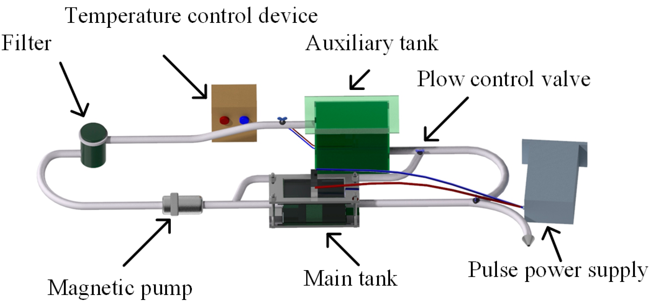
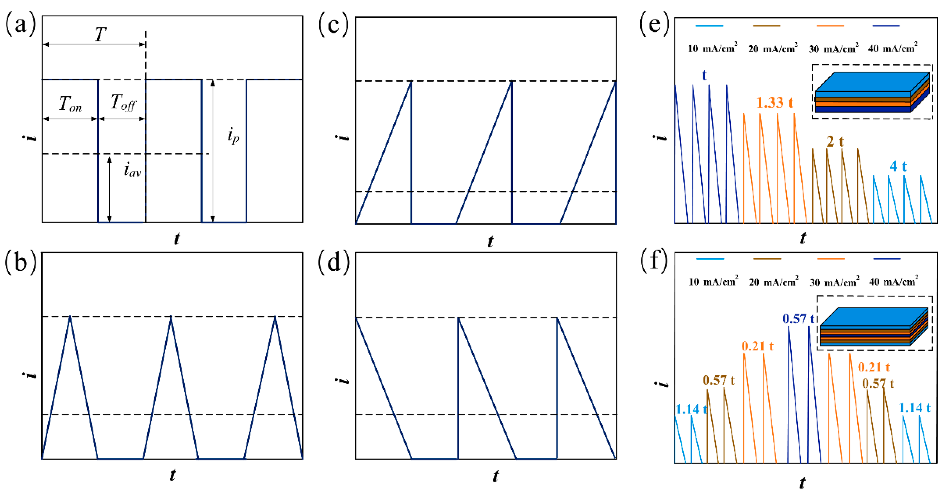
2.1. Experiment Setup and Process
2.2. Characterization
2.3. Corrosion Resistance
3. Results
3.1. Corrosion Resistance Analysis of Single-Layer Ni Coatings
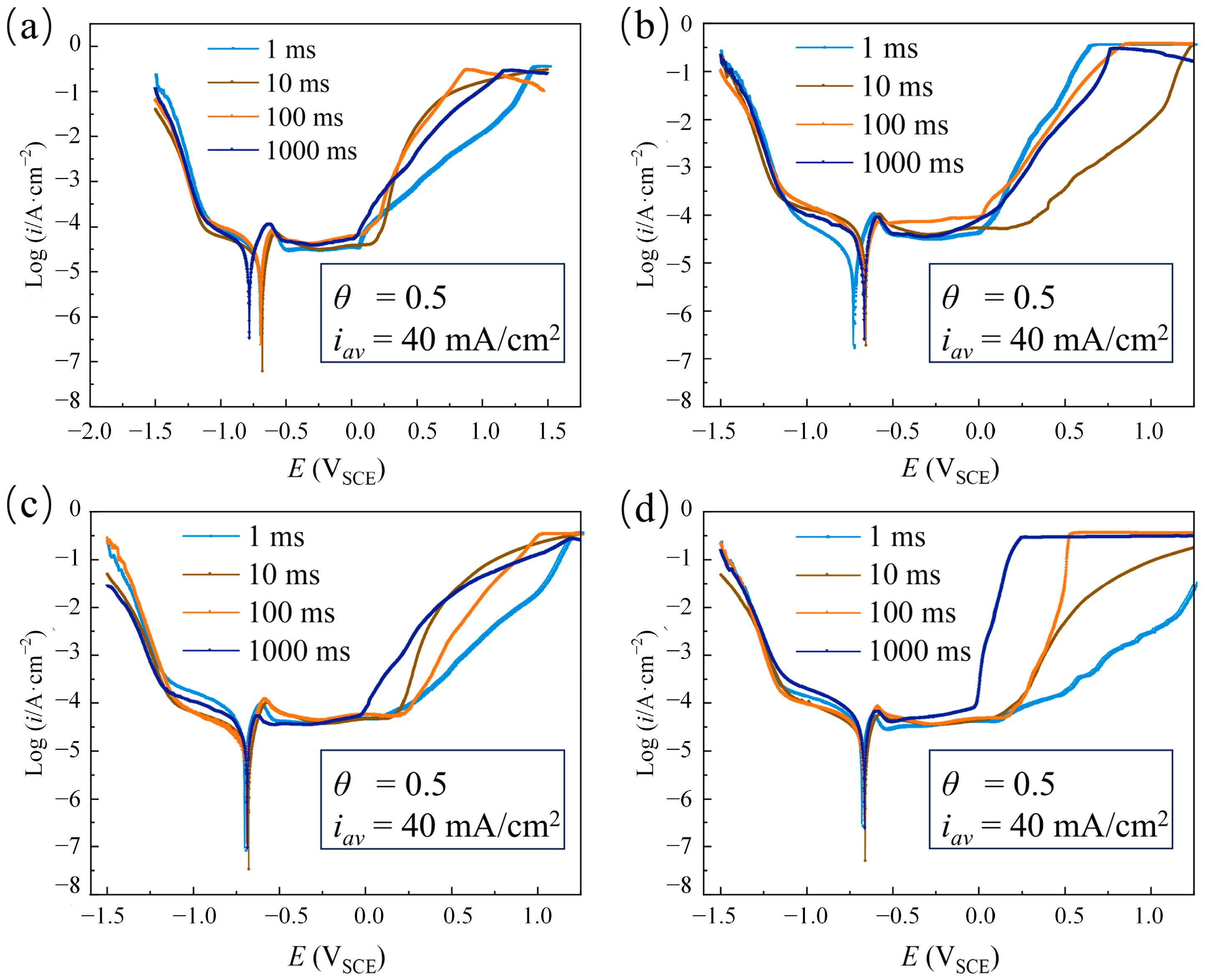
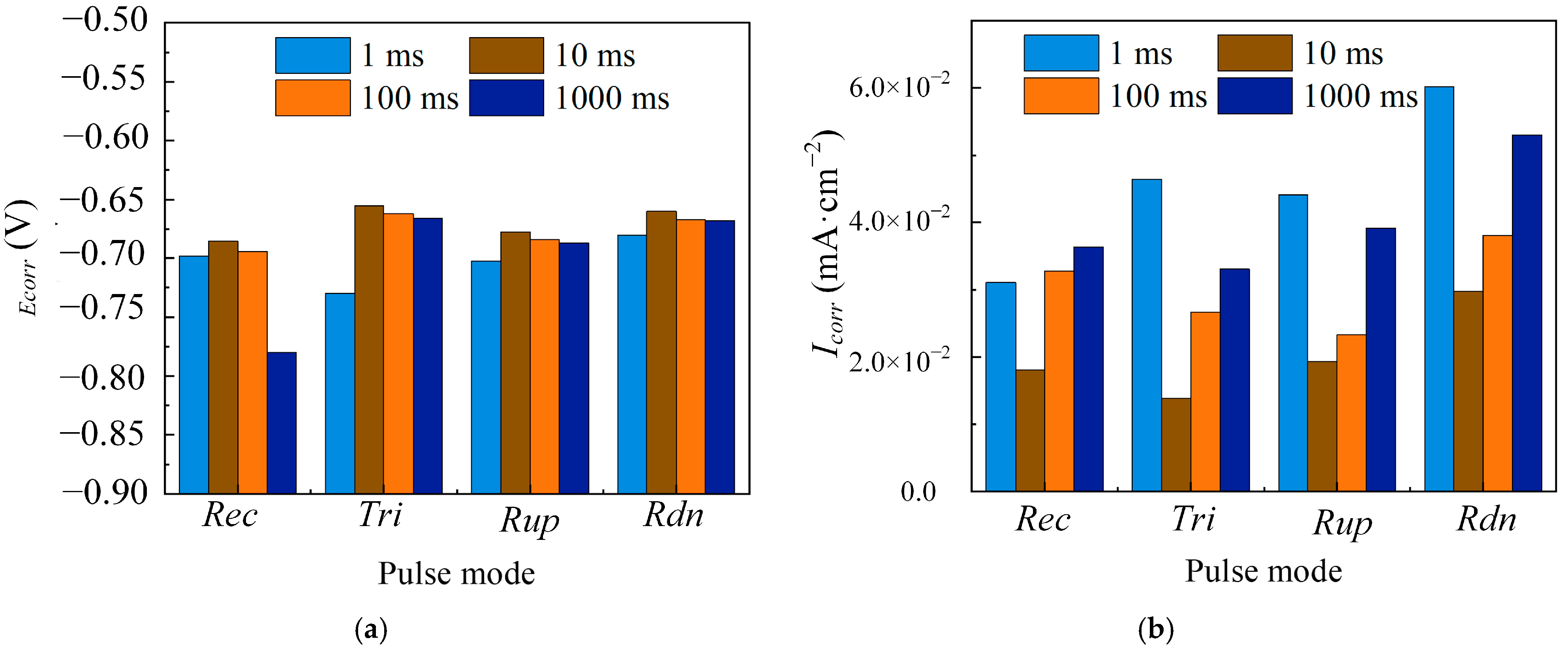
3.1.1. The Effect of Pulse Period
3.1.2. The Effect of Duty Cycle
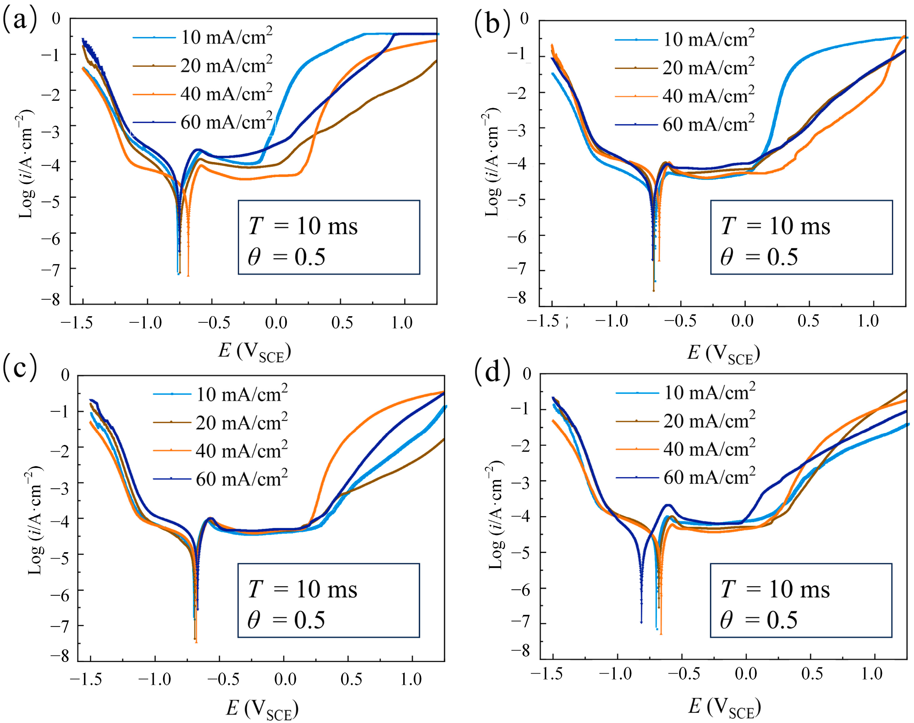
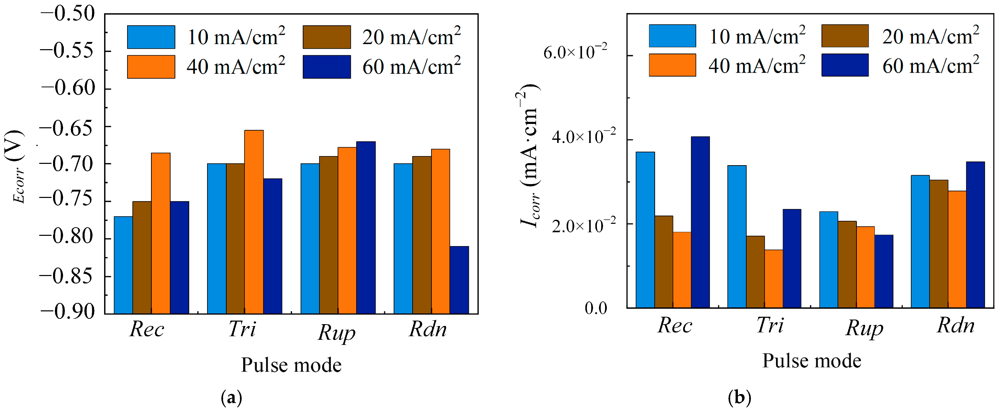
3.1.3. The Effect of Average Current Density
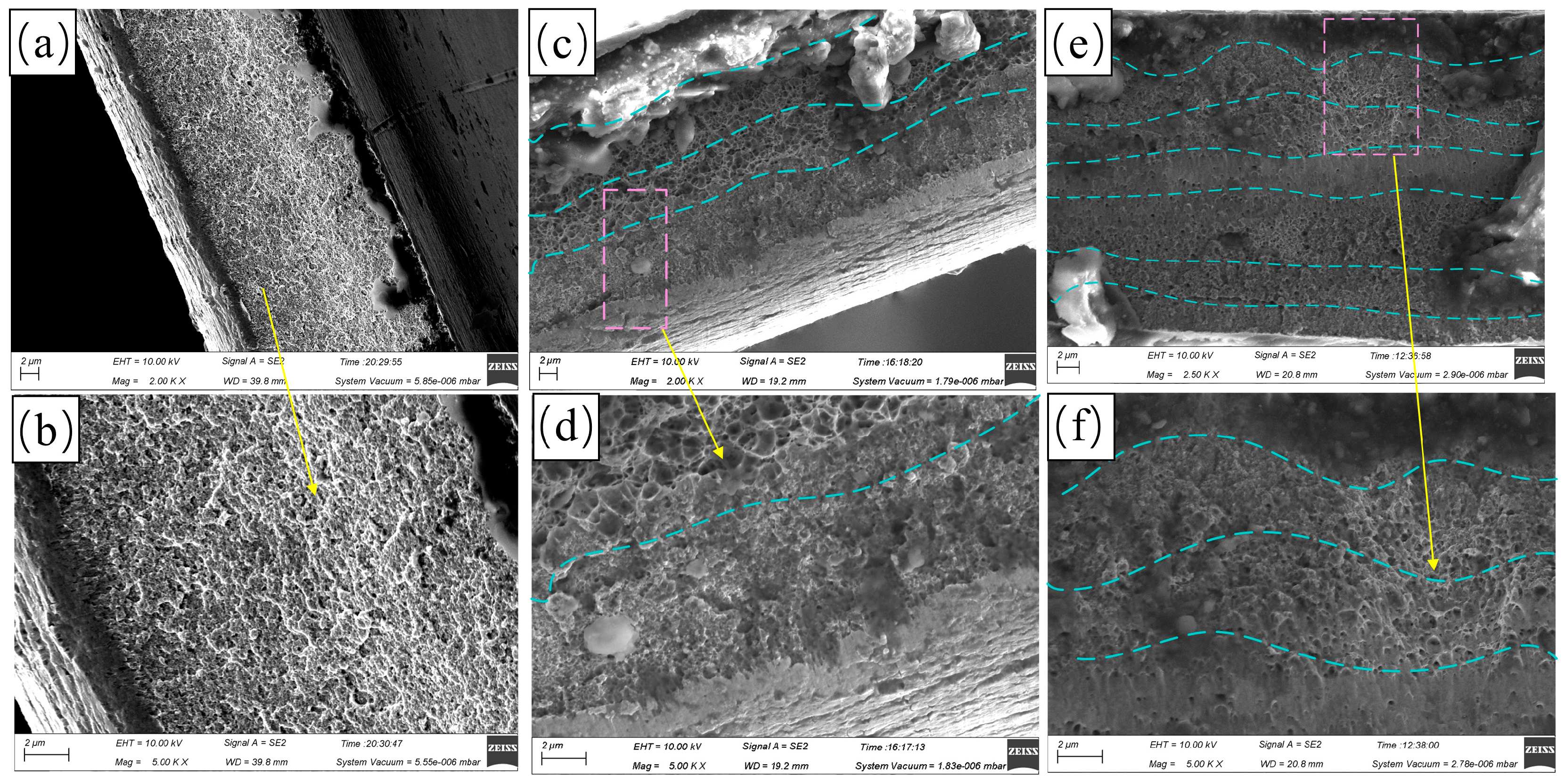
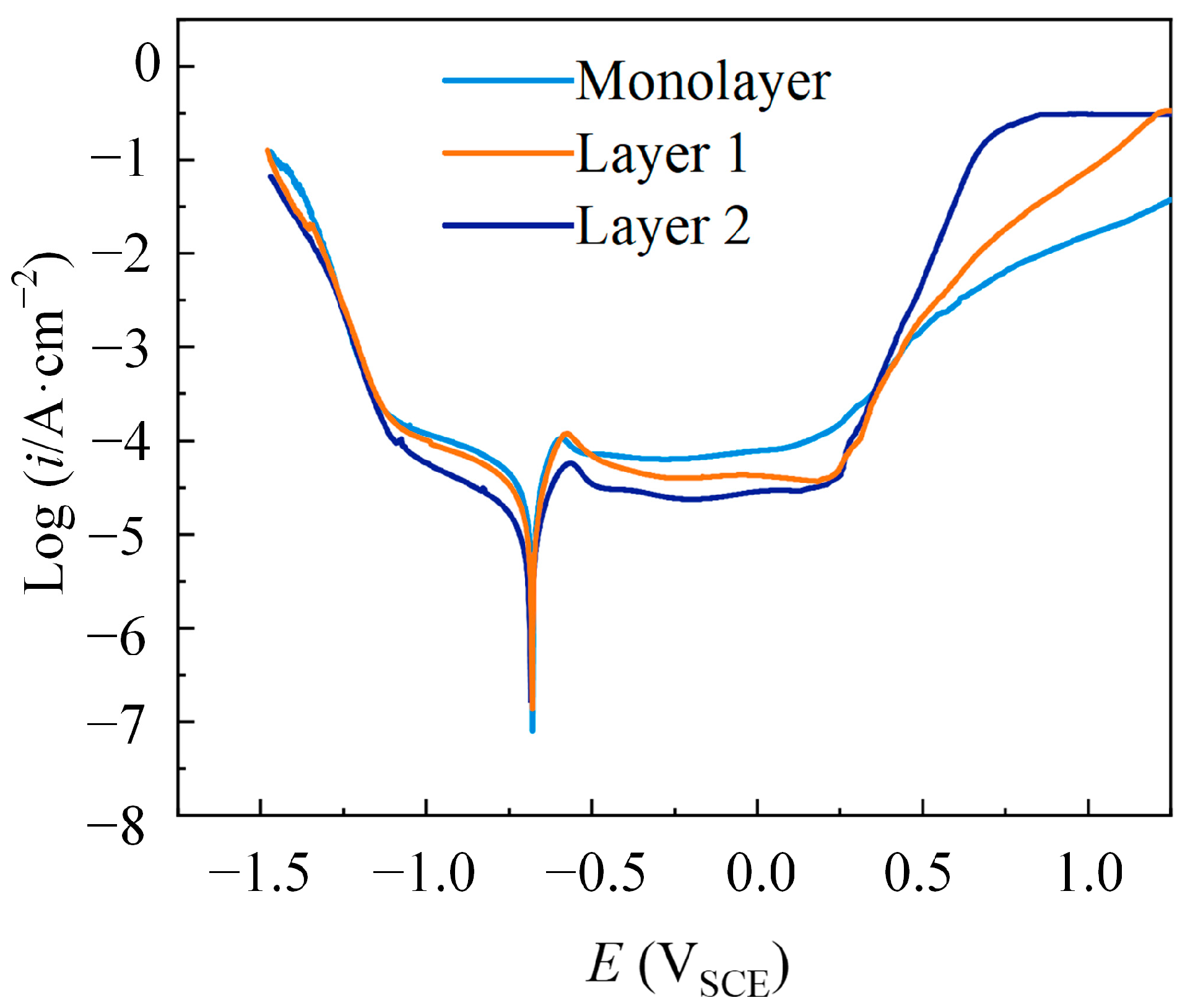
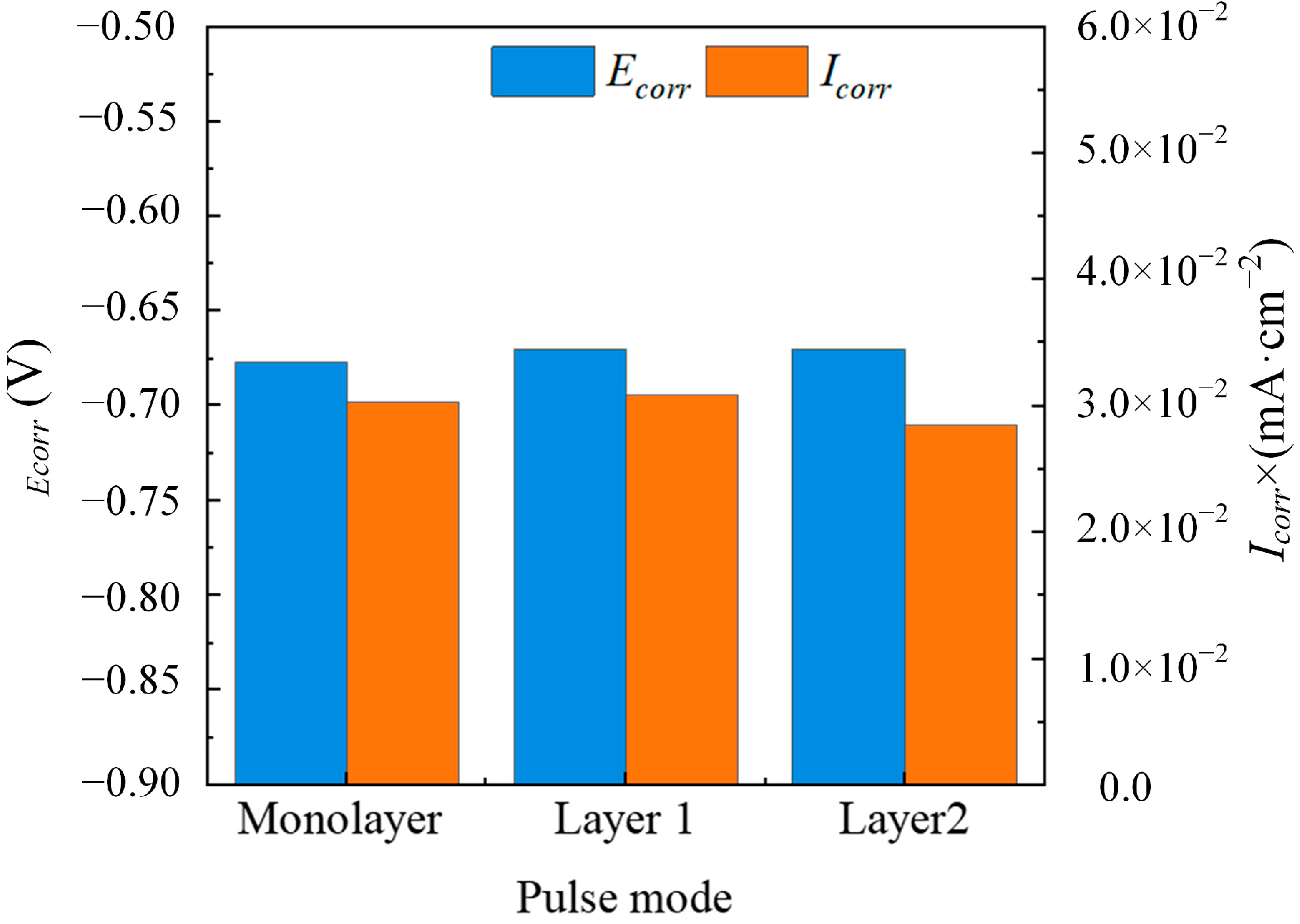
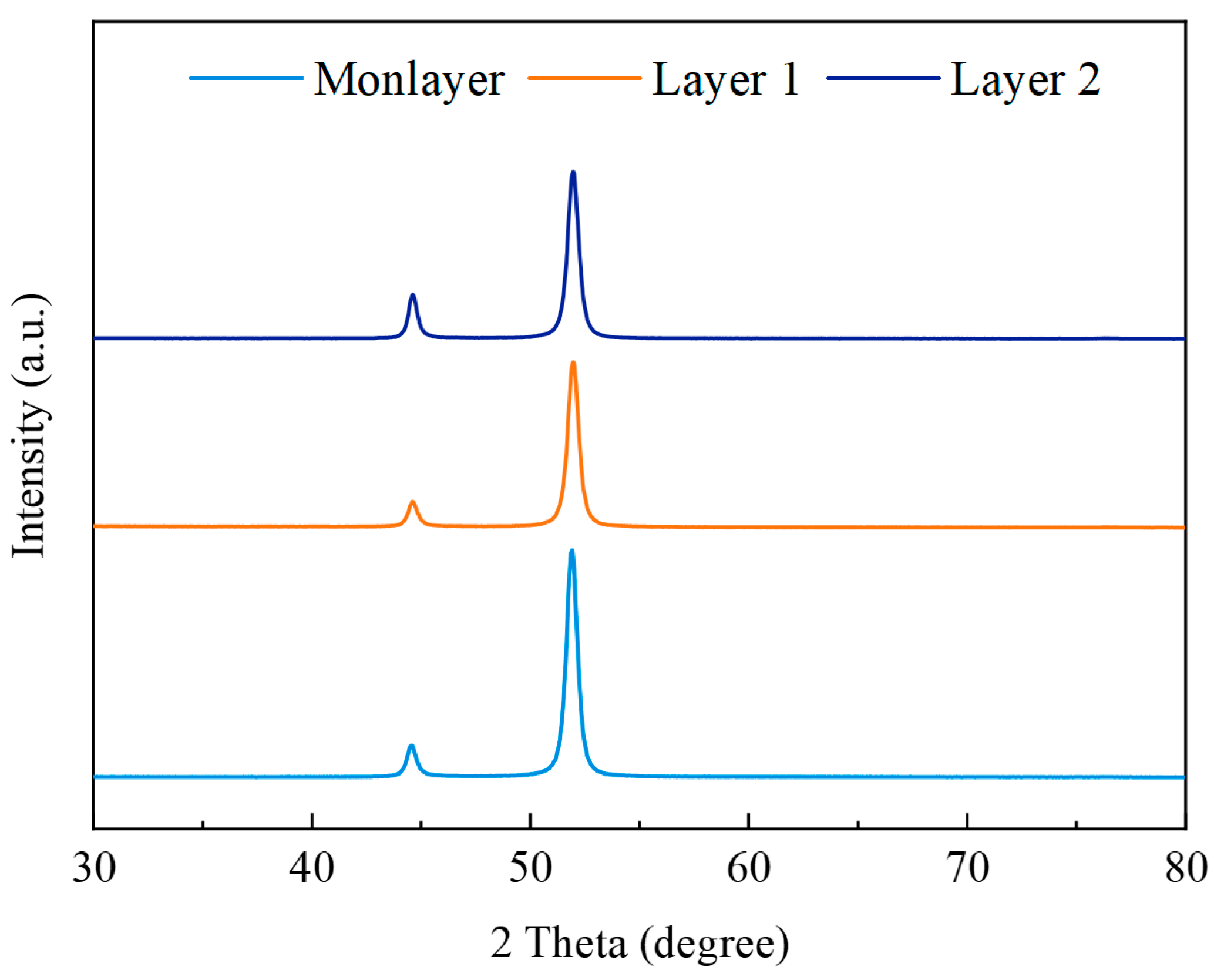
3.2. Corrosion Resistance Analysis of Multilayer Ni Coatings
4. Conclusions
Author Contributions
Funding
Institutional Review Board Statement
Informed Consent Statement
Data Availability Statement
Conflicts of Interest
References
- Oriňáková, R.; Turoňová, A.; Kladeková, D.; Gálová, M.; Smith, R.M. Recent developments in the electrodeposition of nickel and some nickel-based alloys. J. Appl. Electrochem. 2006, 36, 957–972. [Google Scholar] [CrossRef]
- Garlow, J.A.; Barrett, L.K.; Wu, L.; Kisslinger, K.; Zhu, Y.; Pulecio, J.F. Large-Area Growth of Turbostratic Graphene on Ni(111) via Physical Vapor Deposition. Sci. Rep. 2016, 6, 19804. [Google Scholar] [CrossRef] [PubMed]
- Zhang, Y.; Gomez, L.; Ishikawa, F.N.; Madaria, A.; Ryu, K.; Wang, C.; Badmaev, A.; Zhou, C. Comparison of Graphene Growth on Single-Crystalline and Polycrystalline Ni by Chemical Vapor Deposition. J. Phys. Chem. Lett. 2010, 1, 3101–3107. [Google Scholar] [CrossRef]
- Manna, M.; Bandyopadhyay, N.; Bhattacharjee, D. Effect of plating time for electroless nickel coating on rebar surface: An option for application in concrete structure. Surf. Coat. Technol. 2008, 202, 3227–3232. [Google Scholar] [CrossRef]
- Šupicová, M.; Rozik, R.; Trnková, L.; Oriňáková, R.; Gálová, M. Influence of boric acid on the electrochemical deposition of Ni. J. Solid State Electrochem. 2006, 10, 61–68. [Google Scholar] [CrossRef]
- Saini, A.; Singh, G.; Mehta, S.; Singh, H.; Dixit, S. A review on mechanical behaviour of electrodeposited Ni-composite coatings. Int. J. Interact. Des. Manuf. 2023, 17, 2247–2258. [Google Scholar] [CrossRef]
- Mosayebi, S.; Rezaei, M.; Mahidashti, Z. Comparing corrosion behavior of Ni and Ni-Mo electroplated coatings in chloride mediums. Colloids Surf. A Physicochem. Eng. Asp. 2020, 594, 124654. [Google Scholar] [CrossRef]
- Feng, X.; Wang, H.; Liu, X.; Wang, C.; Cui, H.; Song, Q.; Huang, K.; Li, N.; Jiang, X. Effect of Al content on wear and corrosion resistance of Ni-based alloy coatings by laser cladding. Surf. Coat. Technol. 2021, 412, 126976. [Google Scholar] [CrossRef]
- Naziri Mehrabani, S.A.; Ahmadzadeh, R.; Abdian, N.; Taghizadeh Tabrizi, A.; Aghajani, H. Synthesis of Ni-GO nanocomposite coatings: Corrosion evaluation. Surf. Interfaces 2020, 20, 100546. [Google Scholar] [CrossRef]
- M’hanni, N.; Anik, T.; Touir, R.; Galai, M.; Touhami, M.E.; Rifi, E.H.; Asfari, Z.; Bakkali, S. Effect of additives on nickel-phosphorus deposition obtained by electroless plating: Characterization and corrosion resistance in 3%(mass) sodium chloride medium. Chin. J. Chem. Eng. 2022, 44, 341–350. [Google Scholar] [CrossRef]
- López, J.R.; Flores, L.; Méndez, P.F.; Bueno, J.J.P.; Trejo, G.; Meas, Y. Effect of Boric Acid, Sodium Nitrate, and Sodium Dodecyl Sulfate as Additives on the Hydrogen Permeation during Nickel Electroplating on Palladium Electrodes. J. Electrochem. Soc. 2021, 168, 062516. [Google Scholar] [CrossRef]
- Exbrayat, L.; Creus, J. Synthesis of Zn-Ceria Nanocomposite Coatings from Particle-Free Aqueous Bath in a one Electrodeposition Step Process. Colloid Interface Sci. Commun. 2018, 25, 31–35. [Google Scholar] [CrossRef]
- Hakimi, F.; Ghalkhani, M.; Rashchi, F.; Dolati, A. Pulse electrodeposition synthesis of Ti/PbO2-IrO2 nano-composite electrode to restrict the OER in the zinc electrowinning. J. Environ. Chem. Eng. 2024, 12, 111985. [Google Scholar] [CrossRef]
- Ibáñez, A.; Escudero-Cid, R.; Ocón, P.; Fatás, E. Effect of the pulse plating parameters on the mechanical properties of nickel electrodeposits. Surf. Coat. Technol. 2012, 212, 94–100. [Google Scholar] [CrossRef]
- Wang, D.; Liu, M.; Zhu, Y.; Li, F. Influence of Double-Pulse Electrodeposition Parameters on the Performance of Nickel/Nanodiamond Composite Coatings. Coatings 2021, 11, 1068. [Google Scholar] [CrossRef]
- Sajjadnejad, M.; Omidvar, H.; Javanbakht, M. Influence of pulse operational parameters on pure nickel electrodeposits: Part II. Microhardness and corrosion resistance. Surf. Eng. 2017, 33, 99–101. [Google Scholar] [CrossRef]
- Sivasakthi, P.; Sekar, R.; Bapu, G.N.K.R. Pulse electrodeposited nickel using sulphamate electrolyte for hardness and corrosion resistance. Mater. Res. Bull. 2015, 70, 832–839. [Google Scholar] [CrossRef]
- Nasirpouri, F.; Farmani, A.; Safarpour, S. Ultrasonic-assisted pulse electrodeposition process for producing nanocrystalline nickel films and their corrosion behavior: Competition between mass transport and nucleation. Surf. Coat. Technol. 2024, 487, 130996. [Google Scholar] [CrossRef]
- Tang, P.T.; Watanabet, T.; Andersen, J.E.T.; Bech-Nielsen, G. Improved corrosion resistance of pulse plated nickel through crystallisation control. J. Appl. Electrochem. 1995, 25, 347–352. [Google Scholar] [CrossRef]
- Cheng, W.; Ge, W.; Yang, Q.; Qu, X. Study on the corrosion properties of nanocrystalline nickel electrodepositied by reverse pulse current. Applied Surf. Sci. 2013, 276, 604–608. [Google Scholar] [CrossRef]
- Bahadormanesh, B.; Ghorbani, M. Ni-P/Zn-Ni compositionally modulated multilayer coatings—Part 2: Corrosion and protection mechanisms. Appl. Surf. Sci. 2018, 442, 313–321. [Google Scholar] [CrossRef]
- Imaz, N.; García-Lecína, E.; Díez, J.A. Corrosion properties of double layer nickel coatings obtained by pulse plating techniques. Trans. IMF 2010, 88, 256–261. [Google Scholar] [CrossRef]
- Ghaemi, M.; Binder, L. Effects of direct and pulse current on electrodeposition of manganese dioxide. J. Power Sources 2002, 111, 248–254. [Google Scholar] [CrossRef]
- Wu, W.; Huang, J.; Näther, J.; Omar, N.A.B.; Köster, F.; Lampke, T.; Liu, Y.; Pan, H.; Zhang, Y. Texture orientation, morphology and performance of nanocrystalline nickel coatings electrodeposited from a Watts-type bath: Effects of H3BO3 concentration and plating time. Surf. Coat. Technol. 2021, 424, 127648. [Google Scholar] [CrossRef]
- Sharma, A.; Bhattacharya, S.; Das, S.; Das, K. A Study on the Effect of Pulse Electrodeposition Parameters on the Morphology of Pure Tin Coatings. Met. Mater. Trans. A 2014, 45, 4610–4622. [Google Scholar] [CrossRef]
- Richoux, V.; Diliberto, S.; Boulanger, C.; Lecuire, J.M. Pulsed electrodeposition of bismuth telluride films: Influence of pulse parameters over nucleation and morphology. Electrochim. Acta 2007, 52, 3053–3060. [Google Scholar] [CrossRef]
- Chen, Y.-H.; Huang, S.-J.; Booncam, J.; Liang, J.-T.; Lin, H.-E. Influence of pulse parameters on microstructure and corrosion characteristics of electrodeposited Ni-W alloy coating. Mater. Today Commun. 2024, 38, 108486. [Google Scholar] [CrossRef]
- Li, H.; He, Y.; Luo, P.; Fan, Y.; Yu, H.; Wang, Y.; He, T.; Li, Z.; Zhang, H. Influence of pulse frequency on corrosion resistance and mechanical properties of Ni-W/B4C composite coatings. Colloids Surf. A Physicochem. Eng. Asp. 2021, 629, 127436. [Google Scholar] [CrossRef]
- Wasekar, N.P.; Latha, S.M.; Ramakrishna, M.; Rao, D.S.; Sundararajan, G. Pulsed electrodeposition and mechanical properties of Ni-W/SiC nano-composite coatings. Mater. Des. 2016, 112, 140–150. [Google Scholar] [CrossRef]
- Fan, H.; Zhao, Y.; Jiang, J.; Wang, S.; Shan, W.; Li, Z. Effect of the Pulse Duty Cycle on the Microstructure and Properties of a Jet Electrodeposited Nanocrystalline Copper Coating. Mater. Trans. 2020, 61, 795–800. [Google Scholar] [CrossRef]
- El-Sherik, A.M.; Erb, U.; Page, J. Microstructural evolution in pulse plated nickel electrodeposits. Surf. Coat. Technol. 1997, 88, 70–78. [Google Scholar] [CrossRef]
- Firouzi-Nerbin, H.; Nasirpouri, F.; Moslehifard, E. Pulse electrodeposition and corrosion properties of nanocrystalline nickel-chromium alloy coatings on copper substrate. J. Alloys Compd. 2020, 822, 153712. [Google Scholar] [CrossRef]
- Qin, L.; Lian, J.; Jiang, Q. Effect of grain size on corrosion behavior of electrodeposited bulk nanocrystalline Ni. Trans. Nonferrous Met. Soc. China 2010, 20, 82–89. [Google Scholar] [CrossRef]
- Karimi, S.; Foulkes, F.R. Modeling the Effects of Different Pulse Current Waveforms on Grain Size of Electrodeposited Nickel Coatings. J. Electrochem. Soc. 2012, 159, D659. [Google Scholar] [CrossRef]
- Liu, W.; Li, G.; Wang, Y.; Hao, Z.; Zhang, Y.; Yan, Z.; Zhao, Q.; Chen, J. Facile dynamic current deposition of high tensile gradient Cu foil with (110) preferred orientation. Sci. China Mater. 2023, 66, 597–602. [Google Scholar] [CrossRef]
- Wong, K.P.; Chan, K.C.; Yue, T.M. A study of hardness and grain size in pulse current electroforming of nickel using different shaped waveforms. J. Appl. Electrochem. 2001, 31, 25–34. [Google Scholar] [CrossRef]
- Yanqiu, Y.; Zhixun, W.; Yanchao, Z.; Jiapo, W.; Zhenwei, L.; Zhufeng, Y. Effect of crystallographic orientation on the corrosion resistance of Ni-based single crystal superalloys. Corros. Sci. 2020, 170, 108643. [Google Scholar] [CrossRef]

| Parameters | Descriptions |
|---|---|
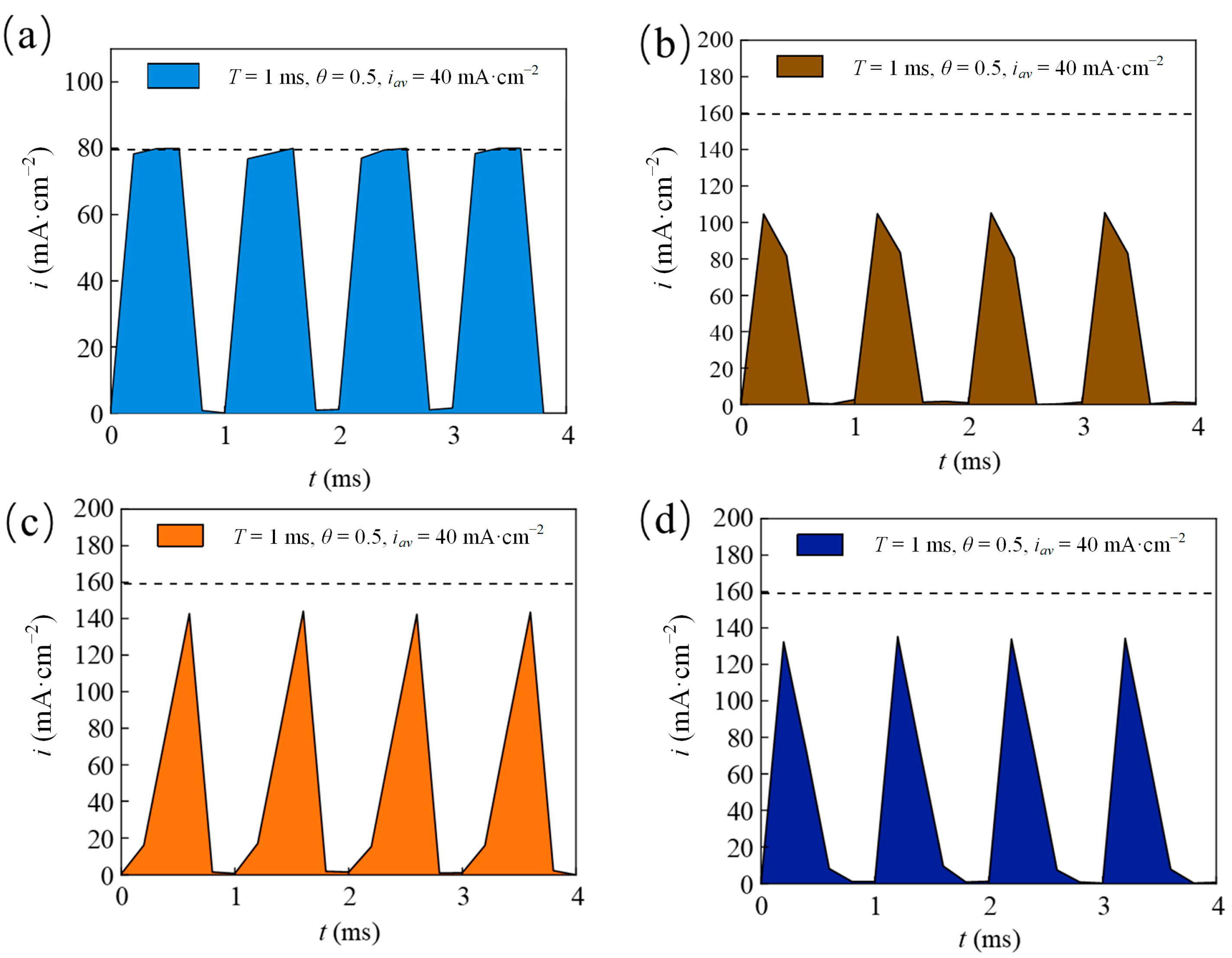
| Pulse current waveforms | Rec, Tri, Rup, Rdn |
| Pulse period T (ms) | 1, 10, 100, 1000 |
| Duty cycle θ | 0.1, 0.3, 0.5, 0.7 |
| Average current density iav (mA/cm2) | 10, 20, 40, 60 |
| Pulse Combination | RTC(111) | RTC(200) |
|---|---|---|
| Monolayer | 5.1 | 95.9 |
| Layer 1 | 6.1 | 94.8 |
| Layer 2 | 10.3 | 89.7 |
Disclaimer/Publisher’s Note: The statements, opinions and data contained in all publications are solely those of the individual author(s) and contributor(s) and not of MDPI and/or the editor(s). MDPI and/or the editor(s) disclaim responsibility for any injury to people or property resulting from any ideas, methods, instructions or products referred to in the content. |
© 2024 by the authors. Licensee MDPI, Basel, Switzerland. This article is an open access article distributed under the terms and conditions of the Creative Commons Attribution (CC BY) license (https://creativecommons.org/licenses/by/4.0/).
Share and Cite
Yan, L.; Zhang, T.; Zhang, H.; Liu, H. Corrosion Resistance Analysis in Nickel Coatings by Electrodeposition with Different Layers and Waveform Combinations. Materials 2025, 18, 2. https://doi.org/10.3390/ma18010002
Yan L, Zhang T, Zhang H, Liu H. Corrosion Resistance Analysis in Nickel Coatings by Electrodeposition with Different Layers and Waveform Combinations. Materials. 2025; 18(1):2. https://doi.org/10.3390/ma18010002
Chicago/Turabian StyleYan, Liang, Tao Zhang, Huajin Zhang, and Huan Liu. 2025. "Corrosion Resistance Analysis in Nickel Coatings by Electrodeposition with Different Layers and Waveform Combinations" Materials 18, no. 1: 2. https://doi.org/10.3390/ma18010002
APA StyleYan, L., Zhang, T., Zhang, H., & Liu, H. (2025). Corrosion Resistance Analysis in Nickel Coatings by Electrodeposition with Different Layers and Waveform Combinations. Materials, 18(1), 2. https://doi.org/10.3390/ma18010002