
Distortion Effect on the UHPC Box Girder with Vertical Webs: Theoretical Analysis and Case Study
by
 , , and
Chenguang Wang
1,
Yaowen Wu
2,
Yuanhai Zhang
1,
Shiying Tang
2,
Weiwen Li
2,*,
Peng Wang
2,* and
Walid Mansour
2,3 1
School of Civil Engineering, Lanzhou Jiaotong University, Lanzhou 730070, China
2
Guangdong Provincial Key Laboratory of Durability for Marine Civil Engineering, Shenzhen University, Shenzhen 518060, China
3
Civil Engineering Department, Faculty of Engineering, Kafrelsheikh University, Kafrelsheikh 6860404, Egypt
*
Authors to whom correspondence should be addressed.
Materials 2024, 17(6), 1303; https://doi.org/10.3390/ma17061303
Submission received: 19 February 2024
/
Revised: 4 March 2024
/
Accepted: 7 March 2024
/
Published: 12 March 2024
(This article belongs to the Special Issue Properties, Structures and Practical Applications of Eco-Friendly Cementitious Materials (Eco-CM))
Abstract
:Distortion deformation usually imposes a potential threat to bridge safety. In order to comprehensively understand the distortion effect on thin-walled ultra-high performance concrete (UHPC) box girders, an innovative approach encompassing the governing distortion differential equation is introduced in this study based on the general definition of distortion angle within the cross-section plane. The analytical results obtained from the proposed method are in accordance with those obtained from the energy method, and exhibit favorable agreement with experimental findings documented in the existing literature. Furthermore, a finite element model is developed on the ANSYS 2021 R1 software platform with the employment of a Shell 63 element. Numerical outcomes are also in good agreement with the experimental data, affirming the validity and reliability of the findings. In addition, parameter analysis results indicate that the distortion angle remains approximately constant at a location approximately 1/10 of the span from the mid-span cross-section of the box girder, regardless of changes in the span-to-depth ratio. Increasing the web thickness yields a notable reduction in the distortion effects, and decreasing the wall thickness can effectively mitigate the distortion-induced transverse bending moment. Compared with normal-strength concrete box girders, UHPC box girders can reduce the distortion angle within the span range, which is beneficial for maintaining the overall stability of the box girders. The outcomes obtained from this study yield engineers an enhanced understanding of distortion effect on the UHPC girder performance.
1. Introduction
Single-cell box girders have become widely utilized in the construction of medium- and long-span highway bridges [1,2,3,4,5,6,7,8,9] due to their aesthetical appearance and exceptional resistance to bending and torsional forces [10,11,12,13,14,15,16,17]. The introduction of ultra-high performance concrete (UHPC), an advanced cementitious composite characterized by its low permeability and ultra-high strength [18], holds promising prospects for the transition of box girder towards thin-walled structures with larger spans and wider rib spacings [19,20,21,22,23,24]. Li et al. [25] showcased the UHPC girder bridge for the Fourth Beijiang River Bridge in Yingde City (in China), which featured a larger span (102 m) and reduced cross-section dimensions (15–20 cm). However, it was observed that the box girder exhibited notable warping effects. The cross-section of thin-walled box girder is susceptible to distortion under torsional effects, which may result in warping stress with a comparable magnitude to the longitudinal bending stresses. As a result, structural safety and passing persons are under the potential threat of distortion-induced damage. In light of this, it is imperative to uncover the distortion effect and address this issue with utmost seriousness.
In recent years, widespread attention has been devoted to investigating the distortional responses of thin-walled girders, with a particular focus on their mechanical properties and design methodologies. The integration of finite element techniques with thin-walled girder theory has led to the development of refined one-dimensional girder elements that incorporate distortion-related characteristics of the cross-section. These advancements have garnered considerable interest in the research community. Li et al. [26] introduced a novel one-dimensional refined girder finite element model that accounted for non-uniform distortional warping and the secondary deformations resulting from distortional moments. This model enabled the accurate analysis of distortional behavior in thin-walled box girders with cantilevered flanges. Zhao et al. [27] proposed a beam element with two torsional degrees of freedom (DOFs) and two distortional DOFs, specifically designed to investigate the eccentric load effects in box girder bridges. Zhu et al. [28] developed a one-dimensional model for a curved composite box girder and formulated a highly efficient finite girder element with 26 DOFs, which considered both constrained torsion and distortion. This element was particularly suitable for analyzing curved composite box girder. Additionally, Arici et al. [29] presented a practical analysis method that addressed the challenges associated with numerical approaches based on the finite element method. Their approach utilized the symplectic approach to overcome these difficulties effectively.
In addition to the above-mentioned finite element method, the theorem of the total potential energy variational method is commonly employed to derive the governing equilibrium equations in the analysis of distortional effects. Xu et al. [30] proposed a novel unified theory for distortion analysis of thin-walled hollow sections based on the Hellinger–Reissner energy variational principle. The results indicate that (1) the distortional shear deformation effects can be neglected in conventional hollow sections of bridge structures, and (2) the first derivative of the distortion angle can serve as an appropriate distortional warping function. It is worth mentioning that these two findings are the foundation of the proposed method in this study. Kermani et al. [31] have developed an elastic analysis method based on the stiffness approach to calculate the distortion effect, and the energy methods have been utilized to formulate the differential equation. Zhang et al. [32] derived analytical solutions for the distortion effects in the elastic stage of single-box structures, employing the energy variational principle. Campo et al. [33] established the governing differential equation using the principle of virtual works and presented a procedure to calculate the distortion effect in horizontally curved trapezoidal box girder bridges. While the aforementioned literature primarily focuses on warping normal stresses, it is important to also consider the distortion warping shear stresses to ensure the safety and serviceability of a thin-walled box girder. Moreover, the inclusion of distortion warping shear stresses provides a new perspective for analyzing the distortion effects of box girders. Stefanou et al. [34] determined the distortion shear flow by integrating the equilibrium equation. The distortion differential equation was developed comprehensively considering the distortion angle that arises from both distortion warping shear stress and external distortion loads. Building upon this methodology, Yoo et al. [35] developed an efficient procedure to evaluate the stresses resulting from distortion in horizontally curved box girders.
While there is extensive research on analyzing the distortion effects of normal-strength concrete box girders, the UHPC girder has not been fully understood. In addition, there is relatively limited research on establishing distortion control differential equations using equilibrium conditions, leaving a challenging issue to theoretically uncover the underlying mechanisms within the cross-section of a distorted UHPC box girder. To address this issue, the main objective of this study is to develop an analytical method based on the equilibrium conditions to uncover the distortion effect on the UHPC box girder. This study defined the distortion angle of UHPC thin-walled box girders through the distortion center, and derived the formulas for the distortion normal stress and the distortion shear stress. Then, the distortion control differential equations were established through the total potential energy variational method and the deformation coordination method. The correctness of proposed deformation coordination method was validated by comparing its equations with that of total potential energy variational method. Finally, the distortion effect on UHPC thin-walled box girders was comprehensively studied by taking a case study as example. These findings yielded engineers with an innovative approach for analyzing the distortion effect on UHPC box girders, offering a comprehensive understanding and reasonable guidelines for practical engineering in this domain.
2. Distortion Warping Stresses
The distortion deformation of a UHPC box girder is shown in Figure 1. Specifically, bt is the half length of top and bottom plates, bw is the girder height; bf is the width of flange plate, δt, δb and δw are the thicknesses of top, bottom and web plates, respectively. Oxyz is the centroidal principal coordinate system, and is the circumferential coordinate, with the counterclockwise direction being positive. The distortion center is denoted as , and points and correspond to the intersections of the horizontal and vertical lines, originating from point , with the web and bottom plates, respectively. After the box girder is distorted, and will move to A’ and B’ and generate distortion angles of γD1 and γD2, respectively. The variation in ∠ADB (i.e., distortion angle γD) is the sum of γD1 and γD2.
Based on the distortion theory for thin-walled box beams, the analysis of distortion in UHPC box beams was conducted under the following fundamental assumptions [36,37,38,39,40,41,42]:
- (1)
- The UHPC box beam was assumed to be in a linear elastic regime, neglecting the micro-cracks in the concrete.
- (2)
- The normal and shear stresses of distortion warping were assumed to be unevenly distributed along the wall thickness.
- (3)
- The UHPC box beam possessed a uniform cross-sectional configuration.
- (4)
- The impact of prestress was disregarded in the analysis.
The tangential displacement (ut) of each plate in the direction can be achieved by the distortion angle γD1 and γD2:
As the distortional shear deformation effects can be neglected, the shear strain was roughly equal to zero. According to the geometric relationship, can be expressed as
where is the distortion warping displacement.
Substitute Equation (1) into Equation (2), the values of distortion angle and can be obtained based on the distortion warping displacement continuity condition ():
It can be seen from Equation (3) that for a vertical web box girder, the distortion angles of the two parts as defined in Figure 1 are the same.
Substituting Equation (3) into Equation (1), and assuming that the shear deformation is zero, it was observed that
where was calculated as
We integrated the perimeter coordinates on both sides of Equation (5),
where is the distortional warping sectorial coordinate. According to the geometric equation, the distortion warping stress () on the cross-section of box girder can be expressed as
According to the self-balance condition that the distortion warping normal stress does not synthesize axial force and bending moment on the cross-section of box girder, the ratio of the distortional warping sectorial coordinates can be computed for the intersection points of web plate with the top and bottom plates:
where is the area of top plate area, is the area of bottom plate, is the area of web plate.
According to the definition of the distortional warping sectorial coordinate, the centroid coordinate position y0 and distortion center position coordinate meet the following relationship:
It is worth noting that, equal to the ratio of the upper and lower parts of the girder height divided by the distortion center D, as shown in Figure 2. For the vertical web box girder, when the plates are bent out of plane, the points A and B are the reverse bending points, i.e., the zero point of the distortional warping sectorial coordinate.
The micro element of was selectively extracted along the longitudinal and circumferential orientations of the thin-walled box girder, as depicted in Figure 3. Based on the equilibrium condition of the micro element on the box wall, a relationship can be established between the distorted warping normal stress and the distorted warping shear flow :
We integrated Equation (10), and the distortion warping shear flow could be obtained as
where is constant shear flow, is the distorted fan static moment, and E is the modulus of elasticity. The distortion warping shear flow does not form torque on the cross section of box girder, i.e.,
Given this, the constant shear flow can be obtained as
where
Substituting Equation (12) into Equation (11), the distortion warping shear flow can be expressed as
The distortion warping shear flow will form distortion moment within the cross section:
where W is the geometric parameter representing the distortion resistance of box girder.
It can be seen from Equation (14) that the distribution of distortion warping shear flow within the cross section plane is only dependent on the distortional sectorial static moment . The distorted fan static moment on the left web can be expressed as
where is the distorted fan static moment at the top of the web.
When the first-order derivative of Equation (17) equals zero, the distortion warping shear flow on the web will achieve an extreme value.
Equation (18) shows that for the vertical web thin-walled box girder, the intersection a and B of the horizontal line and vertical line passing through the distortion center D point and the web and bottom plate of the box girder are not only the zero point of the distortion warping normal stress, but also the extreme point of the distortion warping shear stress.
3. Total Potential Energy Variational Method
The total potential energy of distortion consists of three parts: distortion warping strain energy, distortion frame strain energy, and external load potential energy [43,44,45,46,47,48,49,50,51]. This derivation follows the principle of minimum potential energy. Based on Equation (7), the distortion frame strain energy U1 can be computed as
where represents the distortion-resistant bending moment, which can be expressed as
Through a comparison of Equations (16) and (18), IDW can be further expressed as .
represents the stiffness of the distortion-resistant frame, i.e., the distortion moment required to generate a unit distortion angle within the thin-walled box girder:
where , ,
, and represent the out-plane moment of inertia of the unit length frame for top, bottom and web rods, respectively.
Thus, the distortion frame strain energy can be determined as
Eccentricity load with eccentricity generate and within the cross-section of box girders with internal diaphragms.
In light of this, the distortion-induced external load potential energy can be expressed as
The total potential energy of distortion of box girders with internal diaphragms can be expressed as
Substituting Equations (17), (20) and (21) into Equation (22), the governing distortion differential equation can be derived due to the fact that the first-order variation of total potential energy () is equal to zero.
4. Deformation Coordination Method
The distortion-induced warping normal stresses, distortion-induced warping shear stresses, and externally induced distortion moment can generate distortion angles separately. When using the deformation coordination method to analyze the distortion effect of thin-walled box girders, a unit length thin-walled frame was taken along the girder span direction. Therefore, the distortion moment acting on the thin frame should be its variation rate along the longitudinal direction of the UHPC girder. According to Equation (15), the distortion angle generated by the distortion warping shear flow is
Similarly, the distortion angle caused by distortion external load is
Based on the deformation coordination condition of distortion angles, the distortion angle generated by the UHPC box girder under external distortion loads is equal to the distortion angle jointly produced by distortion bending normal stress and distortion bending shear stress. The distortion angle deformation coordination equation was established as follows:
Substituting Equations (24) and (25) into Equation (26), the governing distortion differential equation for UHPC box girder was obtained based on the deformation coordination method:
As , it is evident that Equations (25) and (29) are equivalent.
5. Numerical Examples
In the previous literature [36], a bench scale test of a cantilever box girder was conducted to investigate the distortion effects. The specific configuration of a tested cantilever box girder is shown in Figure 4. The cross-section of the girder was b × h = 300 mm × 150 mm, with a wall thickness of 3.18 mm. The employed cold-rolled low-carbon steel plate with dimensions of 610 × 610 × 20 mm3 had an elastic modulus of E = 196.2 GPa. The measurement section was chosen as 3/4 of the span from the free end, where the torsion-induced warping stress was minimal, making the measured warping stress values representative.
Furthermore, a finite element model was developed on the ANSYS 2021 R1 software platform using the Shell 63 element. As shown in Table 1, the numerical results of the cantilever box girder were in good agreement with the experimental and analytical results with acceptable errors (<10%), confirming the correctness of the proposed calculation methods in this paper.
In addition, a parametric study was conducted by taking a simply supported box girder bridge as an example. As shown in Figure 5, the bridge span (l) was 40 m in length. The box girder was made of UC120 concrete, with an elastic modulus of E = 43 GPa. An eccentric load of P = 451.0 kN was applied at the top-left corner on the mid-span cross-section of the box girder.
The distribution of distortion-induced warping shear stresses is illustrated in Figure 6. The magnitude of the distortional warping shear stress was symmetrically distributed within the cross-section. On both sides of the cantilever plate, the distortional warping shear stress was in the same direction. In the closed box, the distortional warping shear stress directions on the top and bottom plates and the left and right flanges were opposite. The peak value of the distortional warping shear stress was achieved at the mid-point of the top and bottom plates. The shear force on the cantilever plate reduced when approaching to the end of the cantilever plates. The peak shear stress on the flange was achieved at the mid-point of web plates. In light of this, necessary strengthening measures can be taken at the mid-points of top, bottom and web plates to effectively reduce the distortional warping shear stress within the cross-section plane.
Figure 7 illustrates the variation in distortion angle within the cross-section of girder with respect to the span-to-height ratio (). It can be observed that the maximum distortion angle in the box girder occurred at the mid-span, and gradually decreased towards both ends of UHPC box girder. Moreover, the maximum distortion angle increased with . It is worth mentioning that there were stationary points at approximately /10 from the mid-span of UHPC box girder.
Figure 8 illustrates the variation in the distortion transverse bending moment at the loaded point with respect to the span-to-height ratio (). It can be observed that it shows a similar trend to the distortion angle. It can be observed that the maximum distortion warping normal stress in the UHPC box girder occurred at the mid-span point, and its peak value significantly increased with . It is worth mentioning that there were stationary points at approximately /5 from the mid-span of UHPC box girder.
Figure 9 illustrates the variation in distortion angle at the cross-section of the girder with respect to the height-to-thickness ratio of the web pate (). With an increase in , the distortion angle significantly increased and gradually decreased towards both ends of the UHPC girder. Therefore, the increase in web thickness was an effective approach to reduce the distortion effects.
Figure 10 illustrates the variation in distortion lateral load at the loaded point with the height-to-thickness ratio of the web plate (). It can be observed that the distortion-induced transverse bending moment gradually decreased with a larger . It is worth mentioning that there were stationary points at approximately /5 from the mid-span of UHPC box girder. Therefore, the reduction in web thickness was an effective approach to reduce the distortion-induced transverse bending moment.
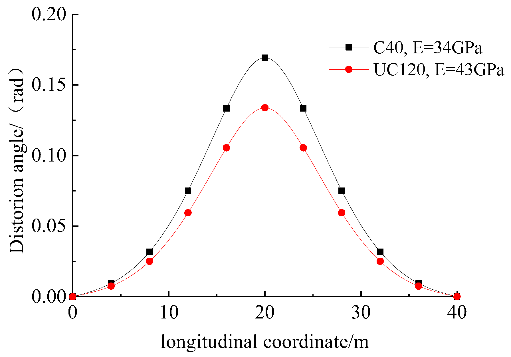
Figure 11 illustrates the variation in the distortion angle within the span range of the normal-strength concrete and the UHPC box girders with the same dimensions (Figure 5). The normal-strength concrete exhibited a compressive strength of 40 MPa and an elastic modulus of 34 GPa. Compared to the normal-strength concrete counterpart, the UHPC box girders could effectively reduce the distortion angle and exhibit enhanced overall stability.
6. Conclusions
This paper introduced an analytical approach to analyze the distortion effect, utilizing the distortion angle of the UHPC box girder. Furthermore, a novel method was proposed based on the equilibrium conditions of deformation coordination. A governing differential equation was derived by employing energy variation calculus grounded in the principle of minimal potential energy. The proposed method was validated by comparing its results with those obtained through the energy method and experimental findings from the existing literature. Additionally, parametric studies were conducted to examine the impact of variations in geometric parameters on the distortion effects of thin-walled box girders. Through comprehensive analysis, several major conclusions were drawn as follows:
- (1)
- For vertically web-plated UHPC box girders, the mid-points on the top, bottom and web plates showcased zero distortional warping normal stress and extreme distortional warping shear stress.
- (2)
- The theoretical derivation process demonstrated that the distortional governing differential equations derived from both the total potential energy variational method and the deformation coordination method were entirely identical, confirming the correctness of the proposed deformation coordination method.
- (3)
- At a distance approximately equal to 1/10 of the span from the middle position of the UHPC box girder, the distortion angle remained constant regardless of the span-to-depth ratio. The distortion effects of the UHPC box girder could be significantly mitigated by increasing the web thickness. Moreover, reducing the thickness of box walls could effectively alleviate the distortion-induced transverse bending moment.
- (4)
- Compared with the normal-strength concrete box girders (C40), the UHPC box girders (UC120) could significantly reduce the distortion angle within the span range, which was beneficial for maintaining the overall stability of the box girders.
Although this study yielded fruitful outcomes, it is important to acknowledge certain limitations. The methodology and associated formulas presented in this study were specifically tailored for the analysis of distortion effects in single-cell box girders featuring vertical web plates. To expand the applicability of this method, future research endeavors could focus on extending the proposed approach to encompass the examination of distortion effects in multi-cell box girders incorporating inclined web plates. Furthermore, the analysis conducted in this study exclusively examined the distortion effects on UHPC box girders under simplified loading conditions. To gain a deeper understanding of the distortion effects under more complex loading conditions, future research should incorporate the nonlinear material properties of both steel and concrete. Additionally, while this paper focused solely on UHPC box girders, it is crucial to extend the investigation to encompass other types of girders, thereby verifying the broader applicability of the proposed model. Despite these limitations, this study provides valuable insights for engineers concerning the distortion effects on UHPC box girders.
Author Contributions
Writing—original draft, C.W., Y.W. and P.W.; Writing—review & editing, Y.Z., S.T., W.L. and W.M. All authors have read and agreed to the published version of the manuscript.
Funding
The authors gratefully acknowledge the financial support provided by the National Natural Science Fund of China (52368020), the Science and Technology Project of Sichuan Province (2019YFG0048), the Shenzhen Natural Science Fund (No. JCYJ20220531101415036, 20220811100052001 and 20231122212907001), and Shenzhen University Young Faculty Research Start-up Project (868-000001032148).
Institutional Review Board Statement
Not applicable.
Informed Consent Statement
Not applicable.
Data Availability Statement
The raw data required to reproduce these findings are available only with direct contact through email to the corresponding author. The processed data required to reproduce these findings are available only with direct contact through email to the corresponding author.
Conflicts of Interest
The authors declare no conflict of interest.
References
- Abbasi, M.; Moustafa, M.A. Probabilistic seismic assessment of as-built and retrofitted old and newly designed skewed multi-frame bridges. Soil Dyn. Earthq. Eng. 2019, 119, 170–186. [Google Scholar] [CrossRef]
- Cai, Q.; Zhu, S. The nexus between vibration-based energy harvesting and structural vibration control: A comprehensive review. Renew. Sustain. Energy Rev. 2022, 155, 111920. [Google Scholar] [CrossRef]
- Mansour, W.; Li, W.; Wang, P.; Badawi, M. Experimental and numerical evaluations of the shear performance of recycled aggregate RC beams strengthened using CFRP sheets. Eng. Struct. 2024, 301, 117368. [Google Scholar] [CrossRef]
- Liang, R.; Wang, H.; Li, J.; Gao, H.; Zheng, W.; Xu, Z. Multiple tuned inerter-based dampers for seismic response mitigation of continuous girder bridges. Soil Dyn. Earthq. Eng. 2021, 151, 106954. [Google Scholar] [CrossRef]
- Lin, Y.; Bi, K.; Zong, Z.; Hao, H.; Lin, J.; Chen, Y. Seismic performance of steel-concrete composite rigid-frame bridge: Shake table test and numerical simulation. J. Bridge Eng. 2020, 25, 04020032. [Google Scholar] [CrossRef]
- Liu, Y.; Mei, Z.; Wu, B.; Bursi, O.S.; Dai, K.S.; Li, B.; Lu, Y. Seismic behaviour and failure-mode-prediction method of a reinforced-concrete rigid-frame bridge with thin-walled tall piers: Investigation by model-updating hybrid test. Eng. Struct. 2020, 208, 110302. [Google Scholar] [CrossRef]
- Hakeem, I.Y.; Mansour, W.; Li, W.; Badawi, M. Analyze the potential for employing internally welded steel plates to improve the shear response of high-strength self-compacting concrete-encased steel beams with large web openings. Eng. Struct. 2024, 304, 117636. [Google Scholar] [CrossRef]
- Wei, B.; Wang, W.H.; Wang, P.; Yang, T.H.; Jiang, L.Z.; Wang, T. Seismic responses of a high-speed railway (HSR) bridge and track simulation under longitudinal earthquakes. J. Earthq. Eng. 2022, 26, 4449–4470. [Google Scholar] [CrossRef]
- Wei, B.; Sun, Z.; Wang, P.; Jiang, L.Z.; Wang, T.; Wang, C.G. Sensitivity of seismic vulnerability curves of high-speed railway bridges to the quantity of ground motion inputs. Structures 2023, 57, 105228. [Google Scholar] [CrossRef]
- Rele, R.R.; Dammala, P.K.; Bhattacharya, S.; Balmukund, R.; Mitoulis, S. Seismic behaviour of rocking bridge pier supported by elastomeric pads on pile foundation. Soil Dyn. Earthq. Eng. 2019, 124, 98–120. [Google Scholar] [CrossRef]
- Saiidi, M.S.; Vosooghi, A.; Choi, H.; Somerville, P. Shake table studies and analysis of a two-span RC bridge model subjected to a fault rupture. J. Bridge Eng. 2014, 19, A4014003. [Google Scholar] [CrossRef]
- Shibata, T.; Kata, K.; Kasuga, A.; Sakai, K. Sustainability evaluation of butterfly web bridge. Struct. Concr. 2018, 19, 422–439. [Google Scholar] [CrossRef]
- Li, W.W.; Li, Z.C.; Chen, H.D.; Zhou, Y.W.; Mansour, W.; Wang, X.Q.; Wang, P. Effects of concrete-stirrup interaction on shear behavior of RC beams under varying shear span-depth ratio scenarios. Structures 2024, 61, 106071. [Google Scholar] [CrossRef]
- Shrestha, B.; Hao, H.; Bi, K. Seismic response analysis of multiple-frame bridges with unseating restrainers considering ground motion spatial variation and SSI. Adv. Struct. Eng. 2015, 18, 873–891. [Google Scholar] [CrossRef]
- Talley, P.C.; Javidialesaadi, A.; Wierschem, N.E.; Denavit, M.D. Evaluation of steel building structures with inerter-based dampers under seismic loading. Eng. Struct. 2021, 242, 112488. [Google Scholar] [CrossRef]
- Wilson, T.; Chen, S.; Mahmoud, H. Analytical case study on the seismic performance of a curved and skewed reinforced concrete bridge under vertical ground motion. Eng. Struct. 2015, 100, 128–136. [Google Scholar] [CrossRef]
- Khandelwal, K.; El-Tawil, S.; Sadek, F. Progressive collapse analysis of seismically designed steel braced frames. J. Constr. Steel Res. 2009, 65, 699–708. [Google Scholar] [CrossRef]
- Li, W.; Lu, Y.; Wang, P.; Jiang, Y.; Wang, L.; Shi, T.; Zheng, K. Comparative study of compressive behavior of confined NSC and UHPC/UHPFRC cylinders externally wrapped with CFRP jacket. Eng. Struct. 2023, 292, 116513. [Google Scholar] [CrossRef]
- Sobuz, M.H.R.; Khan, M.H.; Kabbo, M.K.I.; Alhamami, A.H.; Aditto, F.S.; Sajib, M.S.; Alengaram, J.U.; Mansour, W.; Alam, A. Assessment of mechanical properties with machine learning modeling and durability, and microstructural characteristics of a biochar-cement mortar composite. Constr. Build. Mater. 2024, 411, 134281. [Google Scholar] [CrossRef]
- Saravanan, M.; Goswami, R.; Palani, G.S. Replaceable fuses in earthquake resistant steel structures: A review. Int. J. Steel Struct. 2018, 18, 868–879. [Google Scholar] [CrossRef]
- Bajaber, M.A.; Hakeem, I.Y. UHPC evolution, development, and utilization in construction: A review. J. Mater. Res. Technol. 2021, 10, 1058–1074. [Google Scholar] [CrossRef]
- Neirinck, T.; Semendary, A.A.; Murison, E.; Svecova, D. Performance of UHPC shear keys in box girder bridges-field and finite element study. Eng. Struct. 2023, 296, 116896. [Google Scholar] [CrossRef]
- Mitobaba, J.G.; Wu, X.; Chen, B.; Su, J.; Dong, Z. A modified space truss analogy model for ultimate torsional capacity of ultra-high-performance concrete solid and box beams. Adv. Struct. Eng. 2022, 25, 2427–2443. [Google Scholar] [CrossRef]
- Khan, M.; Lao, J.; Ahmad, M.R.; Kai, M.F.; Dai, J.G. The role of calcium aluminate cement in developing an efficient ultra-high performance concrete resistant to explosive spalling under high temperatures. Constr. Build. Mater. 2023, 384, 131469. [Google Scholar] [CrossRef]
- Li, Z.G.; Yang, X.; Peng, Y.C.; Zhu, Y. Design of 102 m-long UHPC simply-supported structure. World Bridges 2022, 50, 26–30. [Google Scholar]
- Li, X.; Li, L.; Zhou, M.; Wan, S.; Chen, J.; Kang, A. Refined beam finite element model for thin-walled multi-cell box girders considering distortion and secondary distortional moment deformation effect. Eng. Struct. 2024, 298, 117042. [Google Scholar] [CrossRef]
- Zhao, C.; Zhou, Y.; Zhong, X.; Wang, G.; Yang, Q.; Hu, X. A beam-type element for analyzing the eccentric load effect of box girder bridges. Structures 2022, 36, 1–12. [Google Scholar] [CrossRef]
- Zhu, L.; Su, R.K.-L.; Li, M.J. Finite beam element with 26 DOFs for curved composite box girders considering constrained torsion, distortion, shear lag and biaxial slip. Eng. Struct. 2021, 232, 111797. [Google Scholar] [CrossRef]
- Arici, M.; Granata, M.-F.; Longo, G. Symplectic analysis of thin-walled curved box girders with torsion, distortion and shear lag warping effects. Thin-Walled Struct. 2022, 175, 109244. [Google Scholar] [CrossRef]
- Xu, X.; Ye, H.; Zhang, D.Y.; Qiang, S. A unified theory for distortion analysis of thin-walled hollow sections. Int. J. Steel Struct. 2018, 19, 769–786. [Google Scholar] [CrossRef]
- Kermani, B.; Waldron, P. Analysis of continuous box girder bridges including the effects of distortion. Comput. Struct. 1993, 47, 427–440. [Google Scholar] [CrossRef]
- Zhang, Y.L.; Wang, C.; Li, Y.S. Exact distortional behaviour of single-box multicell curved composite box girders with corrugated steel webs in the elastic stage. Eng. Struct. 2023, 297, 116961. [Google Scholar] [CrossRef]
- Campo-Rumoroso, I.; Ramos-Gutiérrez, Ó.R.; Cambronero-Barrientos, F. Distortion analysis of horizontally curved trapezoidal box girder bridges. Eng. Struct. 2023, 282, 115798. [Google Scholar] [CrossRef]
- Stefanou, G.D.; Dritsos, S.; Bakas, G.J. The effects of additional deformations in box-beam bridges on the longitudinal stresses and transverse moments. Comput. Struct. 1983, 16, 613–628. [Google Scholar] [CrossRef]
- Yoo, C.H.; Kang, J.; Kim, K. Stresses due to distortion on horizontally curved tub-girders. Eng. Struct. 2015, 87, 70–85. [Google Scholar] [CrossRef]
- Boswell, L.F.; Zhang, S.H. An experimental investigation of the behaviour of thin-walled box beams. Thin-Walled Struct. 1985, 3, 35–65. [Google Scholar] [CrossRef]
- Fayed, S.; Badr el-din, A.; Basha, A.; Mansour, W. Shear behavior of RC pile cap beams strengthened using ultra-high performance concrete reinforced with steel mesh fabric. Case Stud. Constr. Mater. 2022, 17, e01532. [Google Scholar] [CrossRef]
- Bernardo, L.F.A.; Andrade, J.M.A.; Nunes, N.C.G. Generalized softened variable angle truss-model for reinforced concrete beams under torsion. Mater. Struct. 2015, 48, 2169–2193. [Google Scholar] [CrossRef]
- Jeng, C.H.; Hsu, T.T. A softened membrane model for torsion in reinforced concrete members. Eng. Struct. 2009, 31, 1944–1954. [Google Scholar] [CrossRef]
- Alabdulhady, M.Y.; Sneed, L.H.; Carloni, C. Torsional behavior of RC beams strengthened with PBO-FRCM composite—An experimental study. Eng. Struct. 2017, 136, 393–405. [Google Scholar] [CrossRef]
- Chalioris, C.E.; Karayannis, C.G. Effectiveness of the use of steel fibres on the torsional behaviour of flanged concrete beams. Cem. Concr. Compos. 2009, 31, 331–341. [Google Scholar] [CrossRef]
- Rao, T.G.; Seshu, D.R. Torsion of steel fiber reinforced concrete members. Cem. Concr. Res. 2003, 33, 1783–1788. [Google Scholar] [CrossRef]
- Kwahk, I.; Joh, C.; Lee, J.W. Torsional behavior design of UHPC box beams based on thin-walled tube theory. Engineering 2015, 7, 101. [Google Scholar] [CrossRef]
- Madenci, E.; Fayed, S.; Mansour, W.; Özkılıç, Y.O. Buckling performance of pultruded glass fiber reinforced polymer profiles infilled with waste steel fiber reinforced concrete under axial compression. Steel Compos. Struct. Int. J. 2022, 45, 653–663. [Google Scholar]
- Ferrier, E.; Confrere, A.; Michel, L.; Chanvillard, G.; Bernardi, S. Shear behaviour of new beams made of UHPC concrete and FRP rebar. Compos. Part B Eng. 2016, 90, 1–13. [Google Scholar] [CrossRef]
- Torabi, K.; Ghassabi, M.; Heidari-Rarani, M.; Sharifi, D. Variational iteration method for free vibration analysis of a Timoshenko beam under various boundary conditions. Int. J. Eng. 2017, 30, 1565–1572. [Google Scholar]
- Mohandes, M.; Ghasemi, A.R. Modified couple stress theory and finite strain assumption for nonlinear free vibration and bending of micro/nanolaminated composite Euler–Bernoulli beam under thermal loading. Proc. Inst. Mech. Eng. Part C J. Mech. Eng. Sci. 2017, 231, 4044–4056. [Google Scholar] [CrossRef]
- Akbaş, Ş.D. Forced Vibration Responses of Axially Functionally Graded Beams by using Ritz Method. J. Appl. Comput. Mech. 2021, 7, 109–115. [Google Scholar]
- Mirjavadi, S.S.; Afshari, B.M.; Barati, M.R.; Hamouda, A.M.S. Transient response of porous inhomogeneous nanobeams due to various impulsive loads based on nonlocal strain gradient elasticity. Int. J. Mech. Mater. Des. 2020, 16, 57–68. [Google Scholar] [CrossRef]
- Malikan, M.; Dastjerdi, S. Analytical buckling of FG nanobeams on the basis of a new one variable first-order shear deformation beam theory. Int. J. Eng. Appl. Sci. 2018, 10, 21–34. [Google Scholar] [CrossRef]
- ELWakkad, N.Y.; Heiza, K.M.; Mansour, W. Experimental study and finite element modelling of the torsional behavior of self-compacting reinforced concrete (SCRC) beams strengthened by GFRP. Case Stud. Constr. Mater. 2023, 18, e02123. [Google Scholar] [CrossRef]
Figure 1.
Distortion deformation of UHPC box girder.
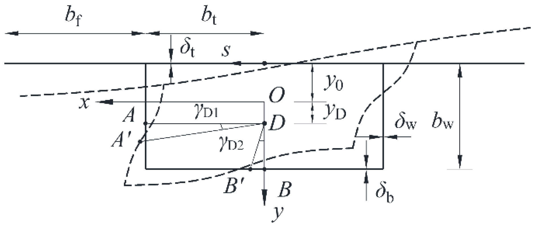
Figure 2.
Distortional warping sectorial coordinate distribution.
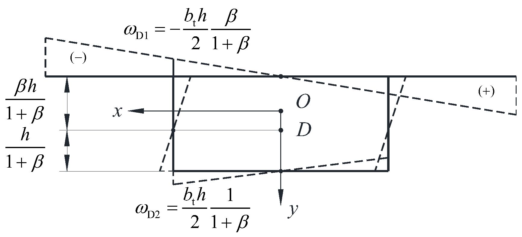
Figure 3.
Thin-walled box girder box wall microelement force diagram.
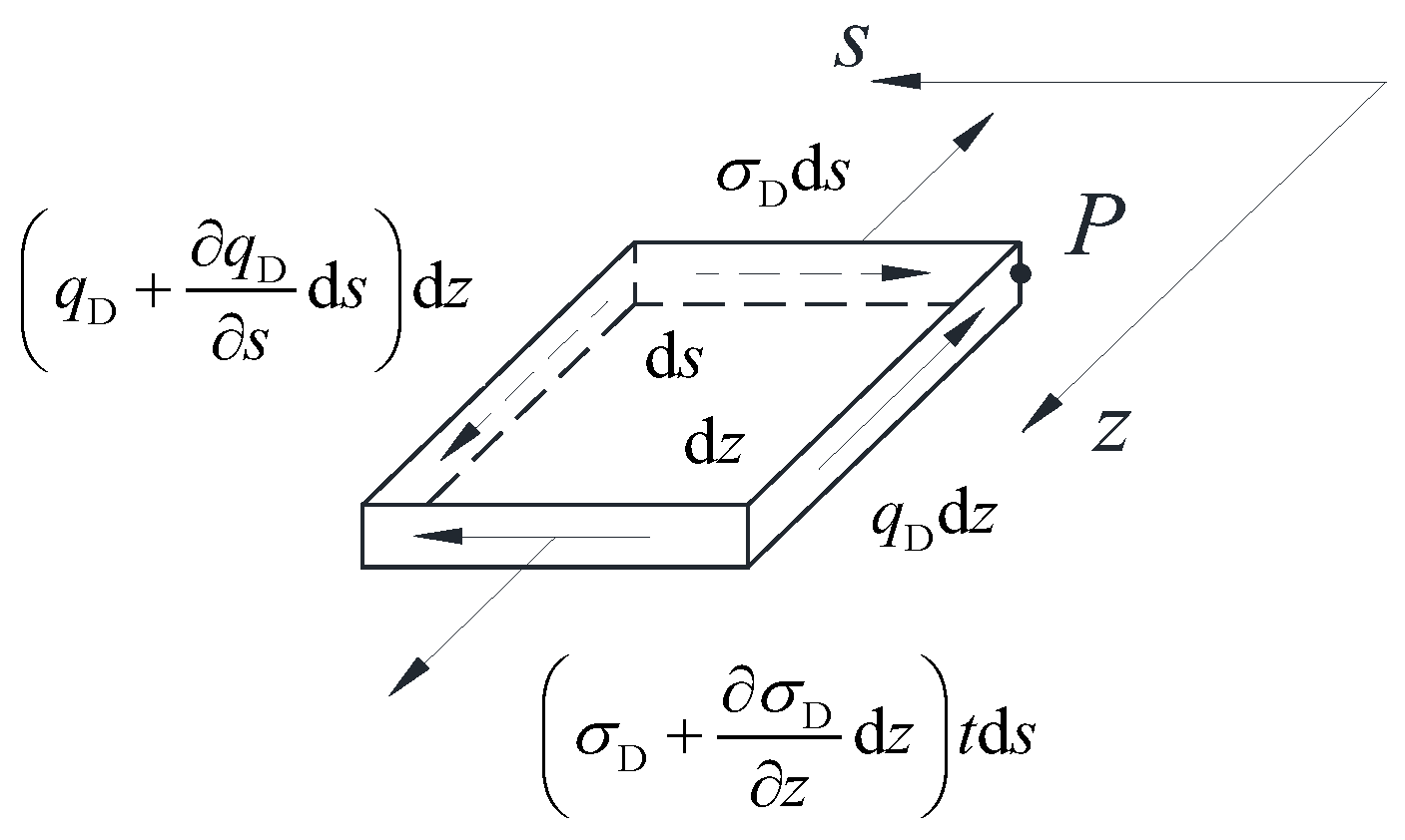
Figure 4.
Configuration of cantilever box girder (unit: mm).
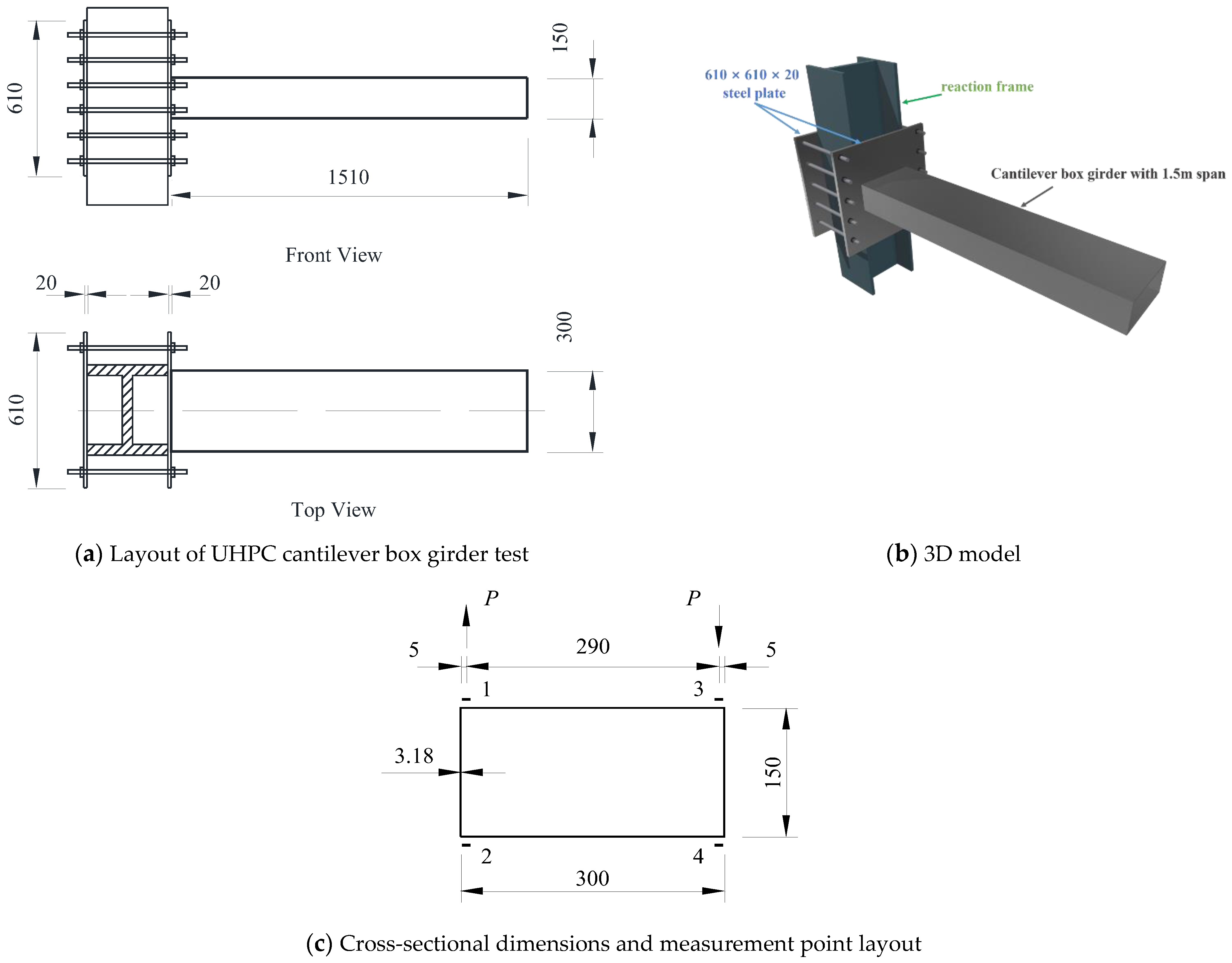
Figure 5.
Simple UHPC support box girder (cm).
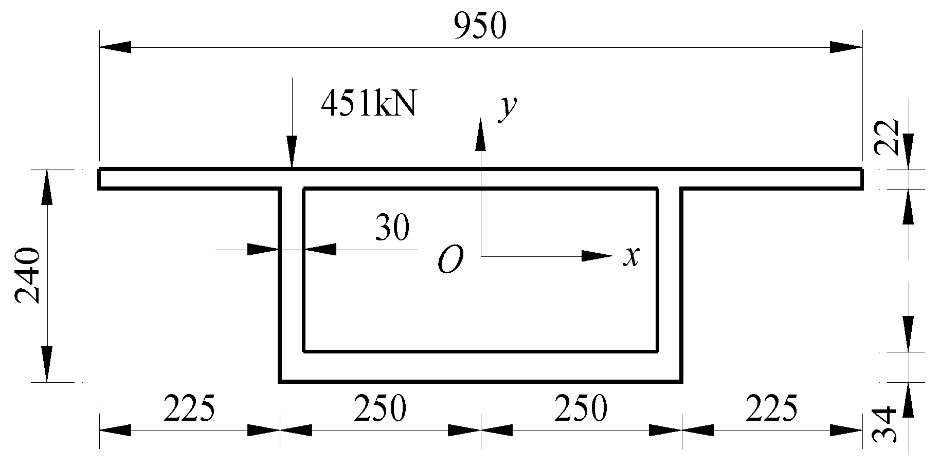
Figure 6.
Distribution of distortion-induced warping shear stresses (green arrows denote the shear stress flow).
Figure 6.
Distribution of distortion-induced warping shear stresses (green arrows denote the shear stress flow).
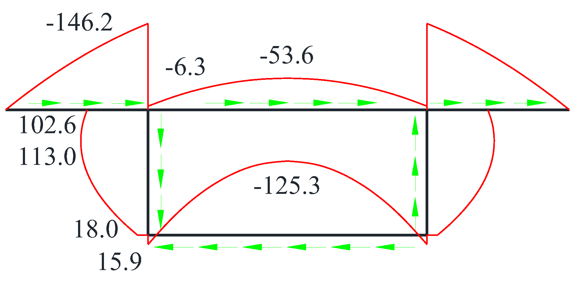
Figure 7.
Variation in distortion angle with respect to the span-to-height ratio.
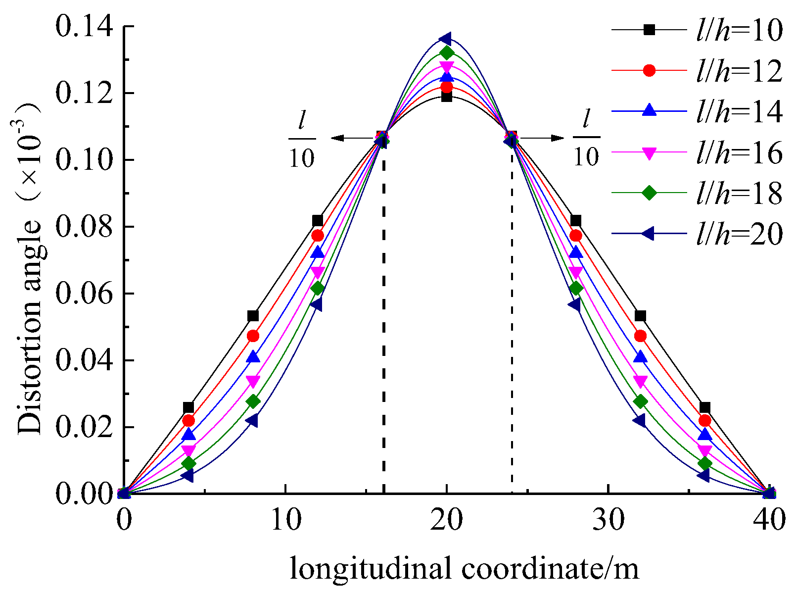
Figure 8.
Variation in distortion-induced transverse bending moment with respect to the span-to-height ratio.
Figure 8.
Variation in distortion-induced transverse bending moment with respect to the span-to-height ratio.
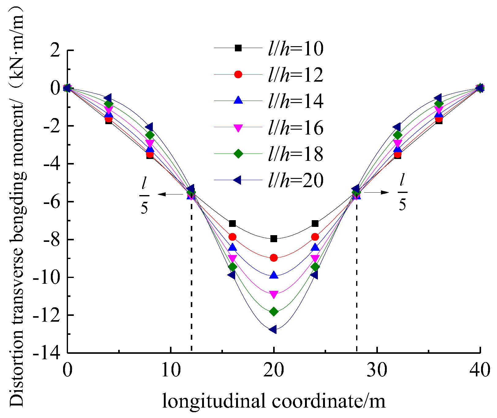
Figure 9.
Variation in distortion angle with respect to the height-to-thickness ratio.
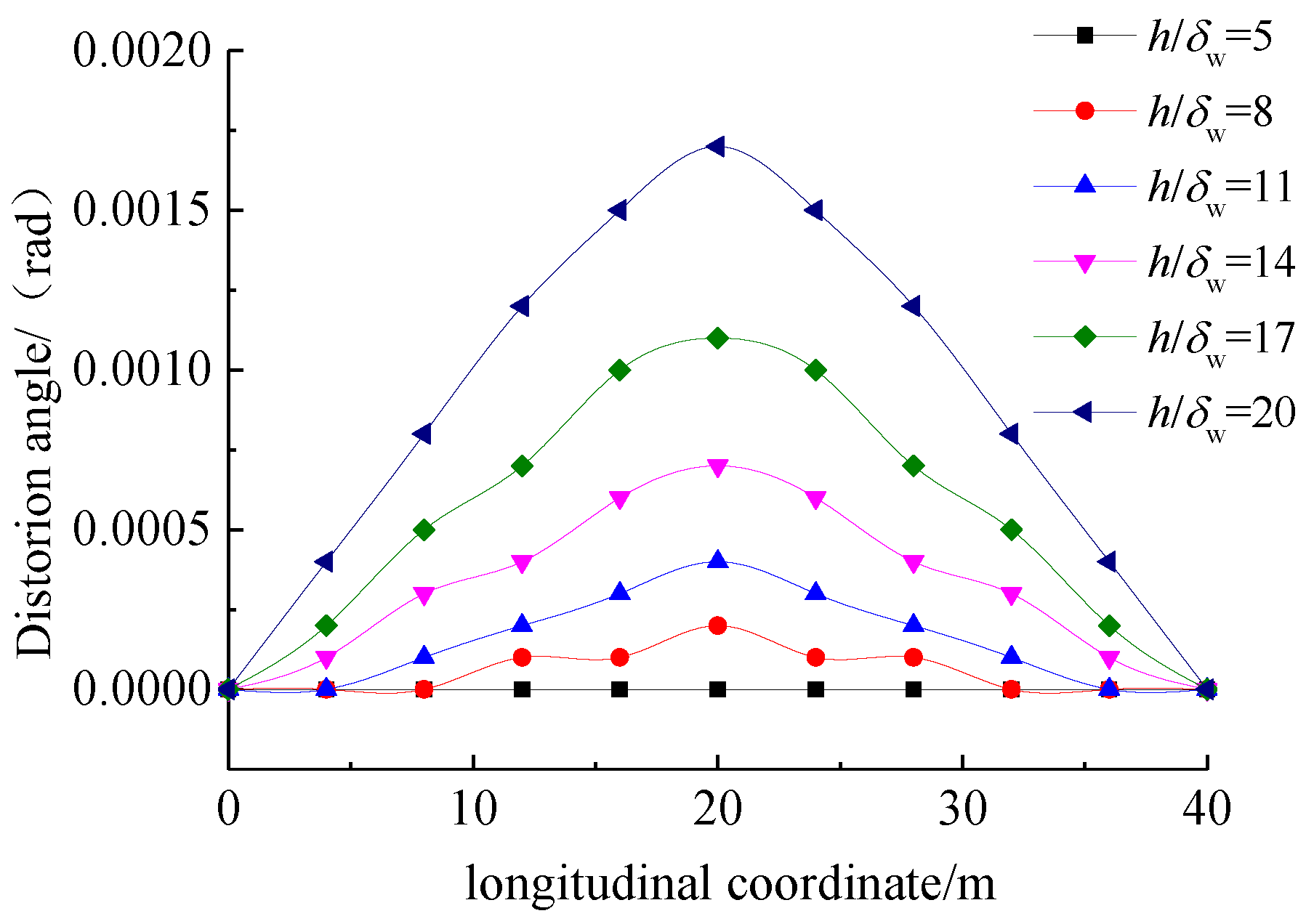
Figure 10.
Variation in distortion transverse bending moment with respect to height-to-thickness ratio.
Figure 10.
Variation in distortion transverse bending moment with respect to height-to-thickness ratio.
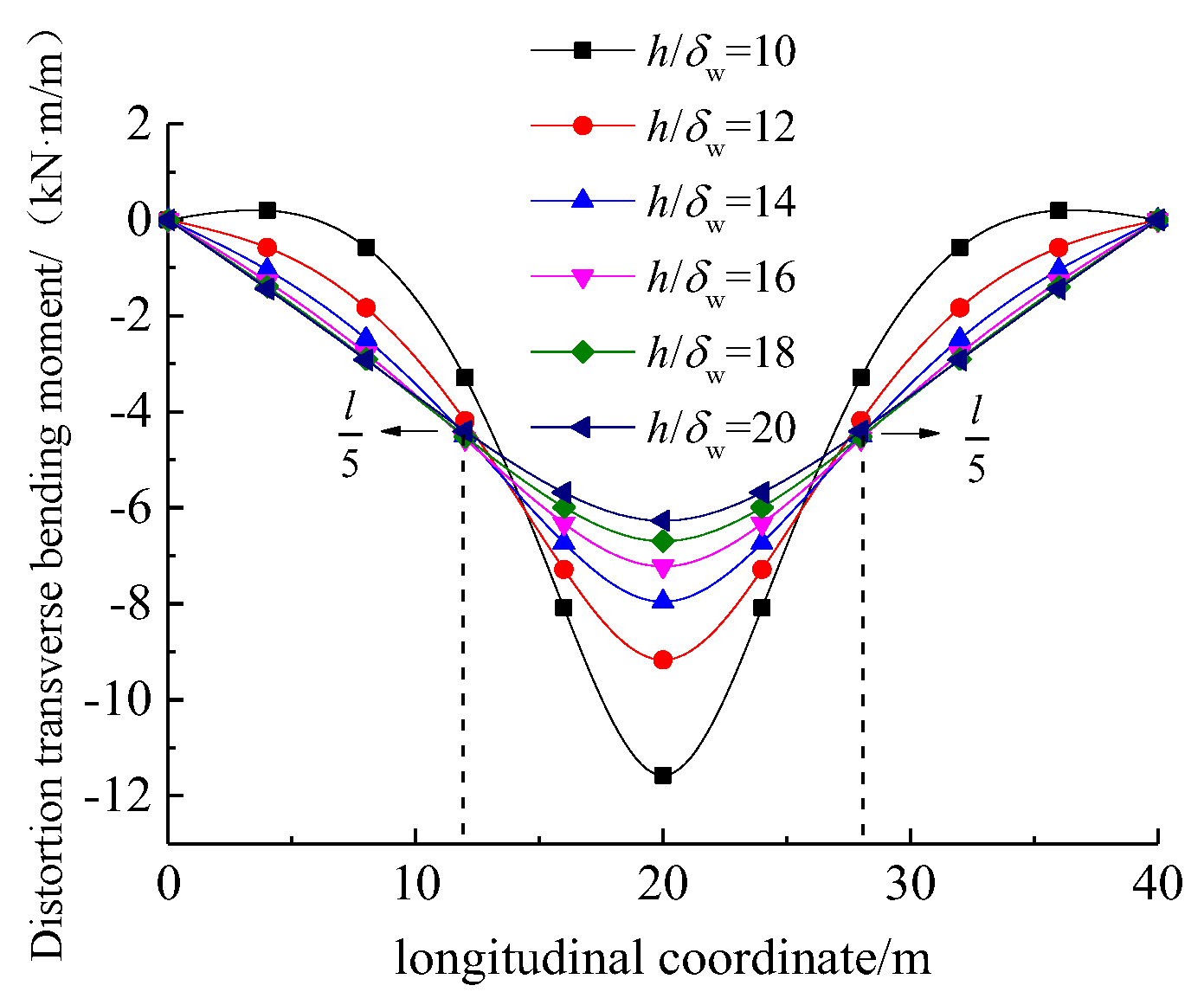
Figure 11.
Comparison between normal-strength concrete and UHPC box girder in terms of distortion angle.
Figure 11.
Comparison between normal-strength concrete and UHPC box girder in terms of distortion angle.

Table 1.
Distortion warping normal stress (unit: MPa).
| Measurement Point | Analytical Solution | Numerical Solution | Experimental Value | Δ1 (%) | Δ2 (%) |
|---|---|---|---|---|---|
| 1 | −33.26 | −34.05 | −31.62 | 4.93 | 7.14 |
| 2 | 33.26 | 34.05 | 32.08 | 3.55 | 5.79 |
| 3 | 33.26 | 34.05 | 32.55 | 2.14 | 4.41 |
| 4 | −33.26 | −34.05 | −33.42 | 0.48 | 1.85 |
Note: Δ1 = (Warping stress analytical solution − Warping stress experimental value)/Warping stress analytical solution × 100%; Δ2 = (Warping stress finite element solution − Warping stress experimental value)/Warping stress finite element solution × 100%.
Disclaimer/Publisher’s Note: The statements, opinions and data contained in all publications are solely those of the individual author(s) and contributor(s) and not of MDPI and/or the editor(s). MDPI and/or the editor(s) disclaim responsibility for any injury to people or property resulting from any ideas, methods, instructions or products referred to in the content. |
© 2024 by the authors. Licensee MDPI, Basel, Switzerland. This article is an open access article distributed under the terms and conditions of the Creative Commons Attribution (CC BY) license (https://creativecommons.org/licenses/by/4.0/).
Share and Cite
MDPI and ACS Style
Wang, C.; Wu, Y.; Zhang, Y.; Tang, S.; Li, W.; Wang, P.; Mansour, W. Distortion Effect on the UHPC Box Girder with Vertical Webs: Theoretical Analysis and Case Study. Materials 2024, 17, 1303. https://doi.org/10.3390/ma17061303
AMA Style
Wang C, Wu Y, Zhang Y, Tang S, Li W, Wang P, Mansour W. Distortion Effect on the UHPC Box Girder with Vertical Webs: Theoretical Analysis and Case Study. Materials. 2024; 17(6):1303. https://doi.org/10.3390/ma17061303
Chicago/Turabian StyleWang, Chenguang, Yaowen Wu, Yuanhai Zhang, Shiying Tang, Weiwen Li, Peng Wang, and Walid Mansour. 2024. "Distortion Effect on the UHPC Box Girder with Vertical Webs: Theoretical Analysis and Case Study" Materials 17, no. 6: 1303. https://doi.org/10.3390/ma17061303
Note that from the first issue of 2016, this journal uses article numbers instead of page numbers. See further details here.