


Microhardness and Microstructure Analysis of the LPBF Additively Manufactured 18Ni300


Abstract
1. Introduction
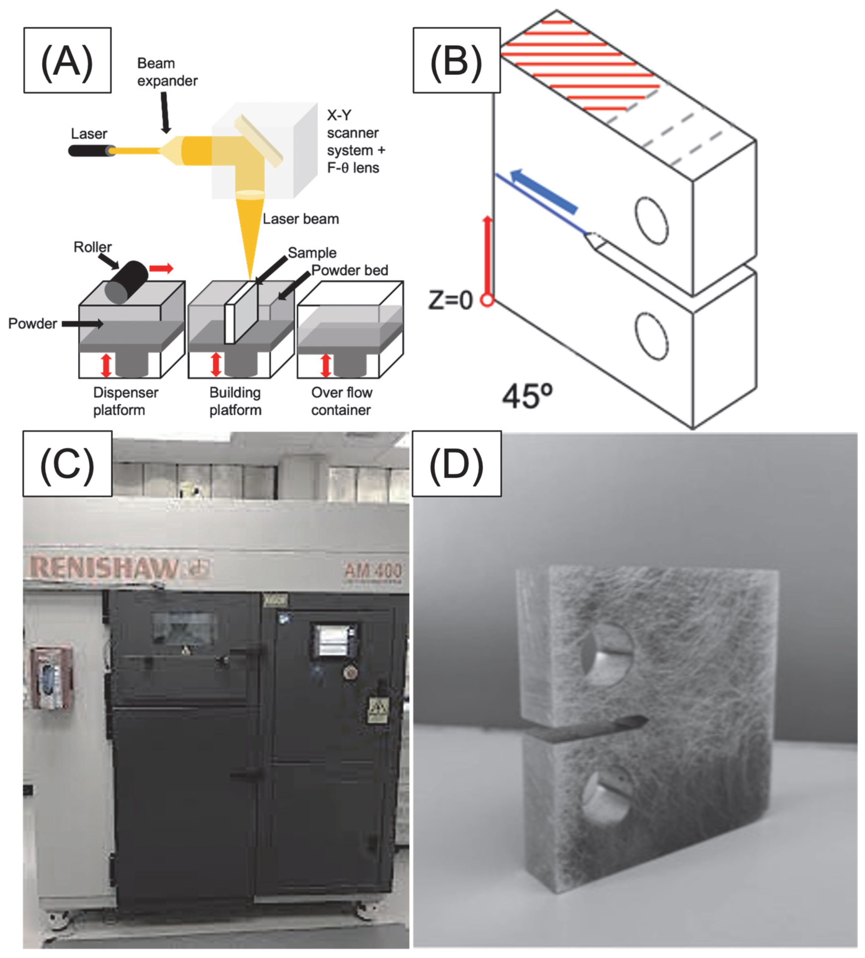
2. Material and Methods
3. Results and Discussion
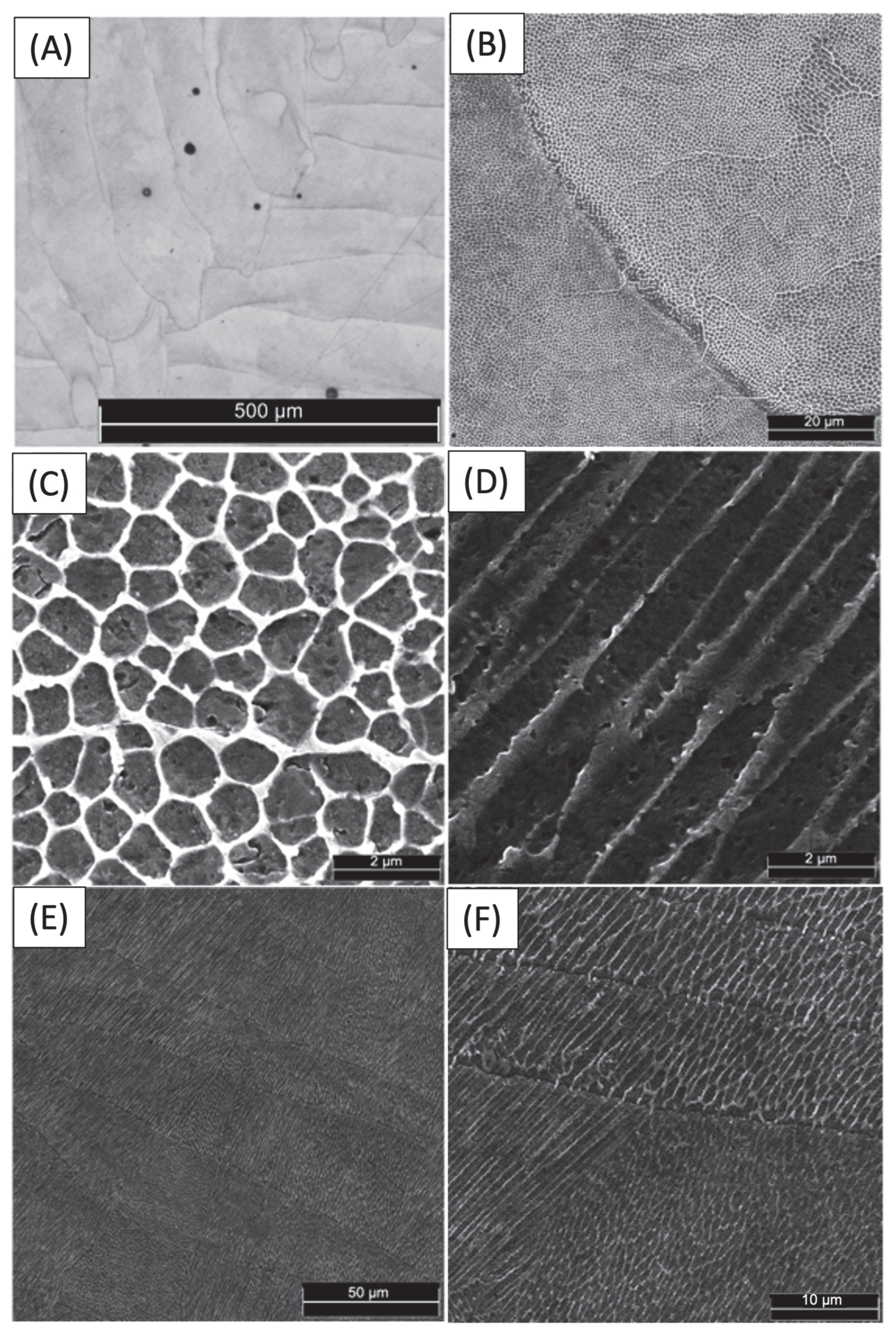
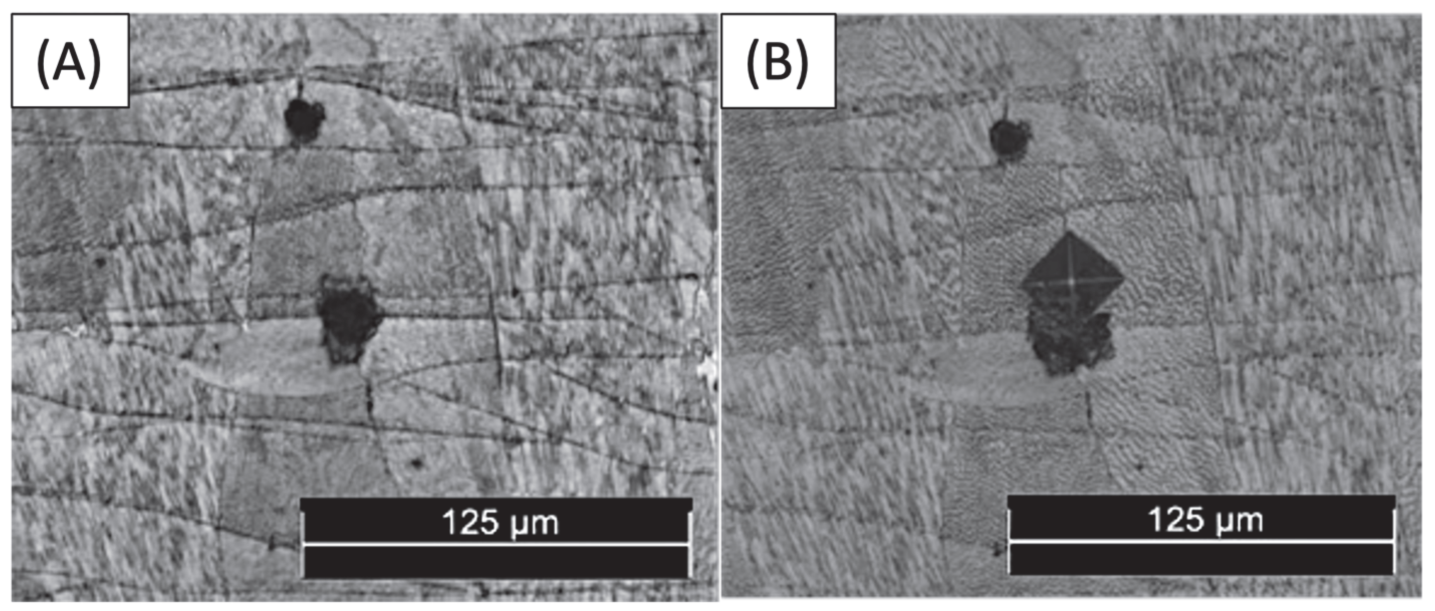
3.1. Microstructure
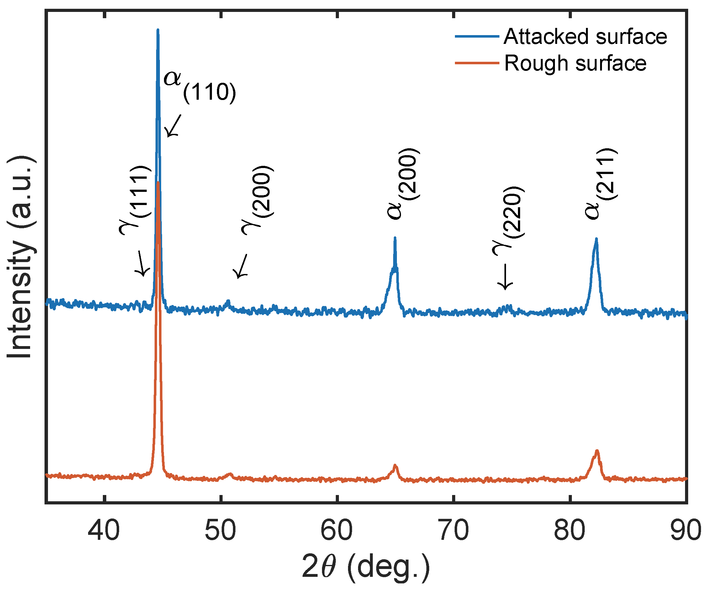
3.2. Phase Analysis
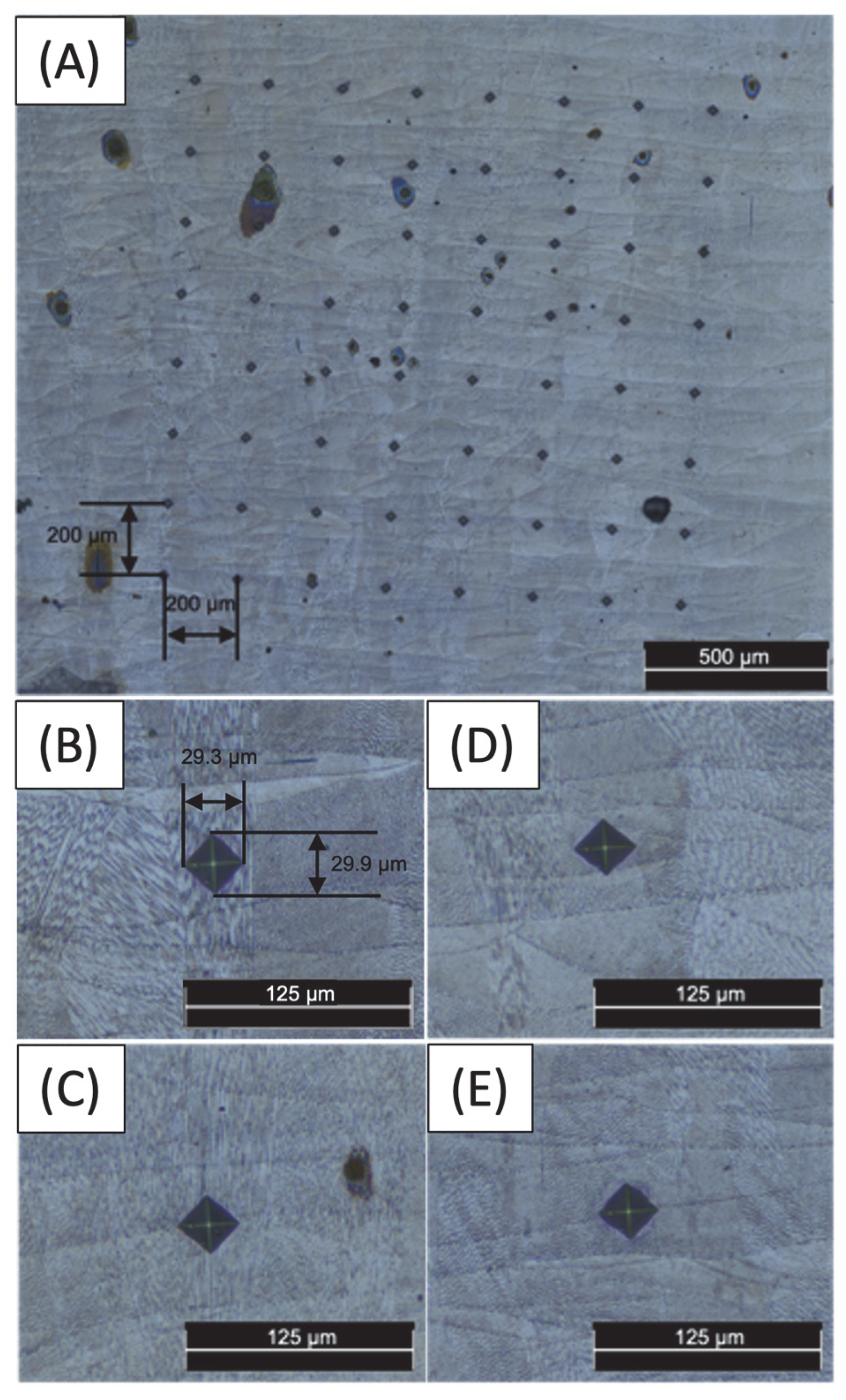
3.3. Microhardness
4. Conclusions
- (1)
- Cellular structures present a higher hardness than columnar structures due to the higher presence of dislocation of austenite cells attributed to the fine-grain microstructures.
- (2)
- The enhanced strength of joined structures compared to that of a single structure was conclusively attributed to nickel segregations at the edges of the structures. This finding is based on the existence of RA in the structure boundaries, which can be attributed to the segregation of solute elements, mainly nickel, at the boundaries of cells during solidification. The hardness between joined structures and single structures increases by 3–5%.
- (3)
- The absence of fusion causes a reduction in the hardness of the material in that region owing to the absence of martensitic phases and structural connections. This phenomenon is attributed to the inability of the material to achieve its full strength potential due to the compromised microstructure in the affected area.
Author Contributions
Funding
Institutional Review Board Statement
Informed Consent Statement
Data Availability Statement
Acknowledgments
Conflicts of Interest
References
- Gardan, N. Knowledge Management for Topological Optimization Integration in Additive Manufacturing. Int. J. Manuf. Eng. 2014, 2014, 356256. [Google Scholar] [CrossRef]
- Zhu, J.; Zhou, H.; Wang, C.; Zhou, L.; Yuan, S.; Zhang, W. A Review of Topology Optimization for Additive Manufacturing: Status and Challenges. Chin. J. Aeronaut. 2021, 34, 91–110. [Google Scholar] [CrossRef]
- Gibson, I.; Rosen, D.W.; Stucker, B. Additive Manufacturing Technologies: Rapid Prototyping to Direct Digital Manufacturing; Springer: Cham, Switzerland, 2021; Volume 17, ISBN 978-3-030-56126-0. [Google Scholar]
- Prathyusha, A.L.R.; Raghu Babu, G. A Review on Additive Manufacturing and Topology Optimization Process for Weight Reduction Studies in Various Industrial Applications. Mater. Today Proc. 2022, 62, 109–117. [Google Scholar] [CrossRef]
- Vrancken, B.; Thijs, L.; Kruth, J.P.; Van Humbeeck, J. Heat Treatment of Ti6Al4V Produced by Selective Laser Melting: Microstructure and Mechanical Properties. J. Alloys Compd. 2012, 541, 177–185. [Google Scholar] [CrossRef]
- Wong, K.V.; Hernandez, A. A Review of Additive Manufacturing. Int. Sch. Res. Not. 2012, 2023, 208760. [Google Scholar] [CrossRef]
- Yadroitsev, I.; Krakhmalev, P.; Yadroitsava, I.; Johansson, S.; Smurov, I. Energy Input Effect on Morphology and Microstructure of Selective Laser Melting Single Track from Metallic Powder. J. Mater. Process. Technol. 2013, 213, 606–613. [Google Scholar] [CrossRef]
- Sivarupan, T.; Balasubramani, N.; Saxena, P.; Nagarajan, D.; El Mansori, M.; Salonitis, K.; Jolly, M.; Dargusch, M.S. A Review on the Progress and Challenges of Binder Jet 3D Printing of Sand Moulds for Advanced Casting. Addit. Manuf. 2021, 40, 101889. [Google Scholar] [CrossRef]
- Bandyopadhyay, A.; Zhang, Y.; Bose, S. Recent Developments in Metal Additive Manufacturing. Curr. Opin. Chem. Eng. 2020, 28, 96–104. [Google Scholar] [CrossRef] [PubMed]
- Kempen, K.; Thijs, L.; Van Humbeeck, J.; Kruth, J.P. Mechanical Properties of AlSi10Mg Produced by Selective Laser Melting. Phys. Procedia 2012, 39, 439–446. [Google Scholar] [CrossRef]
- Thijs, L.; Kempen, K.; Kruth, J.P.; Van Humbeeck, J. Fine-Structured Aluminium Products with Controllable Texture by Selective Laser Melting of Pre-Alloyed AlSi10Mg Powder. Acta Mater. 2013, 61, 1809–1819. [Google Scholar] [CrossRef]
- Simonelli, M.; Tse, Y.Y.; Tuck, C. Effect of the Build Orientation on the Mechanical Properties and Fracture Modes of SLM Ti–6Al–4V. Mater. Sci. Eng. 2014, 616, 1–11. [Google Scholar] [CrossRef]
- Simonelli, M.; Tse, Y.Y.; Tuck, C. Microstructure of Ti-6Al-4V Produced by Selective Laser Melting. J. Phys. Conf. Ser. 2012, 371, 012084. [Google Scholar] [CrossRef]
- Aboulkhair, N.T.; Everitt, N.M.; Ashcroft, I.; Tuck, C. Reducing Porosity in AlSi10Mg Parts Processed by Selective Laser Melting. Addit. Manuf. 2014, 1, 77–86. [Google Scholar] [CrossRef]
- Mercelis, P.; Kruth, J.P. Residual Stresses in Selective Laser Sintering and Selective Laser Melting. Rapid Prototyp. J. 2006, 12, 254–265. [Google Scholar] [CrossRef]
- Bai, Y.; Wang, D.; Yang, Y.; Wang, H. Effect of Heat Treatment on the Microstructure and Mechanical Properties of Maraging Steel by Selective Laser Melting. Mater. Sci. Eng. A 2019, 760, 105–117. [Google Scholar] [CrossRef]
- ISO/ASTM 52900; Additive Manufacturing—General Principles—Fundamentals and Vocabulary. ASTM Committee: West Conshohocken, PA, USA, 2023.
- Santonocito, D.; Fintová, S.; Di Cocco, V.; Iacoviello, F.; Risitano, G.; D’Andrea, D. Comparison on Mechanical Behavior and Microstructural Features between Traditional and AM AISI 316L. Fatigue Fract. Eng. Mater. Struct. 2023, 46, 379–395. [Google Scholar] [CrossRef]
- Bajaj, P.; Hariharan, A.; Kini, A.; Kürnsteiner, P.; Raabe, D.; Jägle, E.A. Steels in Additive Manufacturing: A Review of Their Microstructure and Properties. Mater. Sci. Eng. 2020, 772, 138633. [Google Scholar] [CrossRef]
- Shamantha, C.R.; Narayanan, R.; Iyer, K.J.L.; Radhakrishnan, V.M.; Seshadri, S.K.; Sundararajan, S.; Sundaresan, S. Microstructural Changes during Welding and Subsequent Heat Treatment of 18Ni (250-Grade) Maraging Steel. Mater. Sci. Eng. A 2000, 287, 43–51. [Google Scholar] [CrossRef]
- Sun, L.; Simm, T.H.; Martin, T.L.; McAdam, S.; Galvin, D.R.; Perkins, K.M.; Bagot, P.A.J.; Moody, M.P.; Ooi, S.W.; Hill, P.; et al. A Novel Ultra-High Strength Maraging Steel with Balanced Ductility and Creep Resistance Achieved by Nanoscale β-NiAl and Laves Phase Precipitates. Acta Mater. 2018, 149, 285–301. [Google Scholar] [CrossRef]
- Garrison, W.M.; Banerjee, M.K. Martensitic Non-Stainless Steels: High Strength and High Alloy. In Reference Module in Materials Science and Materials Engineering; Elsevier: Amsterdam, The Netherlands, 2018. [Google Scholar]
- Decker, R.F. 18% Nickel Maraging Steel. Trans. ASM 1962, 55, 58. [Google Scholar]
- Stopyra, W.; Gruber, K.; Smolina, I.; Kurzynowski, T.; Kuźnicka, B. Laser Powder Bed Fusion of AA7075 Alloy: Influence of Process Parameters on Porosity and Hot Cracking. Addit. Manuf. 2020, 35, 101270. [Google Scholar] [CrossRef]
- Tian, Y.; Gontcharov, A.; Gauvin, R.; Lowden, P.; Brochu, M. Effect of Heat Treatment on Microstructure Evolution and Mechanical Properties of Inconel 625 with 0.4 Wt% Boron Modification Fabricated by Gas Tungsten Arc Deposition. Mater. Sci. Eng. A 2017, 684, 275–283. [Google Scholar] [CrossRef]
- Tian, Y.; Chekir, N.; Wang, X.; Nommeots-Nomm, A.; Gauvin, R.; Brochu, M. Microstructure Characterization and Grain Morphology of Alloy 625 with 0.4 Wt% Boron Modification Manufactured by Laser Wire Deposition. Addit. Manuf. 2018, 24, 137–144. [Google Scholar] [CrossRef]
- Conde, F.F.; Avila, J.A.; Oliveira, J.P.; Schell, N.; Oliveira, M.F.; Escobar, J.D. Effect of the As-Built Microstructure on the Martensite to Austenite Transformation in a 18Ni Maraging Steel after Laser-Based Powder Bed Fusion. Addit. Manuf. 2021, 46, 102122. [Google Scholar] [CrossRef]
- Kempen, K.; Yasa, E.; Thijs, L.; Kruth, J.-P.; Van Humbeeck, J. Microstructure and Mechanical Properties of Selective Laser Melted 18Ni-300 Steel. Phys. Procedia 2011, 12, 255–263. [Google Scholar] [CrossRef]
- Cruces, A.S.; Exposito, A.; Branco, R.; Borrego, L.P.; Antunes, F.V.; Lopez-Crespo, P. Study of the Notch Fatigue Behaviour under Biaxial Conditions of Maraging Steel Produced by Selective Laser Melting. Theor. Appl. Fract. Mech. 2022, 121, 103469. [Google Scholar] [CrossRef]
- Brookes, K.J.A. Maraging Steel for Additive Manufacturing—Philipp Stoll’s Paper at DDMC 2016. Met. Powder Rep. 2016, 71, 149–152. [Google Scholar] [CrossRef]
- Deirmina, F.; Davies, P.A.; Casati, R. Effects of Powder Atomization Route and Post-processing Thermal Treatments on the Mechanical Properties and Fatigue Resistance of Additively Manufactured 18Ni300 Maraging Steel. Adv. Eng. Mater. 2022, 24, 2101011. [Google Scholar] [CrossRef]
- Bai, Y.; Zhao, C.; Yang, J.; Hong, R.; Weng, C.; Wang, H. Microstructure and Machinability of Selective Laser Melted High-Strength Maraging Steel with Heat Treatment. J. Mater. Process. Technol. 2021, 288, 116906. [Google Scholar] [CrossRef]
- Karlapudy, S.P.; Nancharaiah, T.; Rao, V.S. Influence of Different Build Orientation and Laser Scan Strategies on Surface Quality, Mechanical and Material Characteristics of 18 Ni-300 Maraging Steel Processed through DMLS. Aust. J. Mech. Eng. 2021, 21, 1381–1395. [Google Scholar] [CrossRef]
- Yves-Christian, H.; Jan, W.; Wilhelm, M.; Konrad, W.; Reinhart, P. Net Shaped High Performance Oxide Ceramic Parts by Selective Laser Melting. Phys. Procedia 2010, 5, 587–594. [Google Scholar] [CrossRef]
- Santos, L.M.S.; Borrego, L.P.; Ferreira, J.A.M.; De Jesus, J.; Costa, J.D.; Capela, C. Effect of Heat Treatment on the Fatigue Crack Growth Behaviour in Additive Manufactured AISI 18Ni300 Steel. Theor. Appl. Fract. Mech. 2019, 102, 10–15. [Google Scholar] [CrossRef]
- Yasa, E.; Kruth, J.P. Microstructural Investigation of Selective Laser Melting 316L Stainless Steel Parts Exposed to Laser Re-Melting. Procedia Eng. 2011, 19, 389–395. [Google Scholar] [CrossRef]
- Jinhui, L.; Ruidi, L.; Wenxian, Z.; Liding, F.; Huashan, Y. Study on Formation of Surface and Microstructure of Stainless Steel Part Produced by Selective Laser Melting. Mater. Sci. Technol. 2010, 26, 1259–1264. [Google Scholar] [CrossRef]
- Cherry, J.A.; Davies, H.M.; Mehmood, S.; Lavery, N.P.; Brown, S.G.R.; Sienz, J. Investigation into the Effect of Process Parameters on Microstructural and Physical Properties of 316L Stainless Steel Parts by Selective Laser Melting. Int. J. Adv. Manuf. Technol. 2015, 76, 869–879. [Google Scholar] [CrossRef]
- Bhardwaj, T.; Shukla, M. Direct Metal Laser Sintering of Maraging Steel: Effect of Building Orientation on Surface Roughness and Microhardness. Mater. Today Proc. 2018, 5, 20485–20491. [Google Scholar] [CrossRef]
- Hu, J.; Zhu, H.; Zhang, J.; Ouyang, M.; Qiu, C.; Duan, J. Effects of TiC Addition on Microstructure, Microhardness and Wear Resistance of 18Ni300 Maraging Steel by Direct Laser Deposition. J. Mater. Process. Technol. 2021, 296, 117213. [Google Scholar] [CrossRef]
- Carter, J.K. Additive Manufacturing of Bioinspired Bulk Gradient Structures to Enhance Mechanical Performance. Ph.D. Thesis, Texas A&M University, College Station, TX, USA, 2018. [Google Scholar]
- ASTM E407-99; Standard Practice for Microetching Metals and Alloys. ASTM: West Conshohocken, PA, USA, 1999.
- Cerezo, P.M.; Aguilera, J.A.; Garcia-Gonzalez, A.; Lopez-Crespo, P. Influence of Porosity on Fatigue Behaviour of 18Ni300 Steel SLM CT Specimens at Various Angles. Materials 2024, 17, 432. [Google Scholar] [CrossRef]
- ASTM E384; Standard Test Method for Measurement of Fatigue Crack Growth Rates. ASTM Committee: West Conshohocken, PA, USA, 2023.
- Mutua, J.; Nakata, S.; Onda, T.; Chen, Z.C. Optimization of Selective Laser Melting Parameters and Influence of Post Heat Treatment on Microstructure and Mechanical Properties of Maraging Steel. Mater. Des. 2018, 139, 486–497. [Google Scholar] [CrossRef]
- Yin, S.; Chen, C.; Yan, X.; Feng, X.; Jenkins, R.; O’Reilly, P.; Lupoi, R. The Influence of Aging Temperature and Aging Time on the Mechanical and Tribological Properties of Selective Laser Melted Maraging 18Ni-300 Steel. Addit. Manuf. 2018, 22, 592–600. [Google Scholar] [CrossRef]
- Wang, D.; Song, C.; Yang, Y.; Bai, Y. Investigation of Crystal Growth Mechanism during Selective Laser Melting and Mechanical Property Characterization of 316L Stainless Steel Parts. Mater. Des 2016, 100, 291–299. [Google Scholar] [CrossRef]
- Herzog, D.; Seyda, V.; Wycisk, E.; Emmelmann, C. Additive Manufacturing of Metals. Acta Mater. 2016, 117, 371–392. [Google Scholar] [CrossRef]
- Stanford, M.; Kibble, K.; Lindop, M.; Mynors, D.; Durnall, C. An Investigation into Fully Melting a Maraging Steel Using Direct Metal Laser Sintering (DMLS). Steel Res. 2008, 2, 847–852. [Google Scholar]
- Tan, C.; Zhou, K.; Tong, X.; Huang, Y.; Li, J.; Ma, W.; Kuang, T. Microstructure and Mechanical Properties of 18Ni-300 Maraging Steel Fabricated by Selective Laser Melting. In Proceedings of the 6th International Conference on Advanced Design and Manufacturing Engineering, Zhuhai, China, 23–24 July 2016; pp. 404–410. [Google Scholar] [CrossRef]
- Kürnsteiner, P.; Wilms, M.B.; Weisheit, A.; Barriobero-Vila, P.; Jägle, E.A.; Raabe, D. Massive Nanoprecipitation in an Fe-19Ni-XAl Maraging Steel Triggered by the Intrinsic Heat Treatment during Laser Metal Deposition. Acta Mater. 2017, 129, 52–60. [Google Scholar] [CrossRef]
- Dai, N.; Zhang, L.C.; Zhang, J.; Zhang, X.; Ni, Q.; Chen, Y.; Yang, C. Distinction in Corrosion Resistance of Selective Laser Melted Ti-6Al-4V Alloy on Different Planes. Corros. Sci. 2016, 111, 703–710. [Google Scholar] [CrossRef]
- Qiu, C.; Adkins, N.J.; Attallah, M.M. Microstructure and Tensile Properties of Selectively Laser-Melted and of HIPed Laser-Melted Ti–6Al–4V. Mater. Sci. Eng. A 2013, 578, 230–239. [Google Scholar] [CrossRef]
- Niendorf, T.; Leuders, S.; Riemer, A.; Richard, H.A.; Tröster, T.; Schwarze, D. Highly Anisotropic Steel Processed by Selective Laser Melting. Metall. Mater. Trans. B 2013, 44, 794–796. [Google Scholar] [CrossRef]
- Ziętala, M.; Durejko, T.; Polański, M.; Kunce, I.; Płociński, T.; Zieliński, W.; Bojar, Z. The Microstructure, Mechanical Properties and Corrosion Resistance of 316 L Stainless Steel Fabricated Using Laser Engineered Net Shaping. Mater. Sci. Eng. A 2016, 677, 1–10. [Google Scholar] [CrossRef]
- Mohd Yusuf, S.; Chen, Y.; Boardman, R.; Yang, S.; Gao, N. Investigation on Porosity and Microhardness of 316L Stainless Steel Fabricated by Selective Laser Melting. Metals 2017, 7, 64. [Google Scholar] [CrossRef]
- Thijs, L.; Sistiaga, M.L.M.; Wauthle, R.; Xie, Q.; Kruth, J.P.; Van Humbeeck, J. Strong Morphological and Crystallographic Texture and Resulting Yield Strength Anisotropy in Selective Laser Melted Tantalum. Acta Mater. 2013, 61, 4657–4668. [Google Scholar] [CrossRef]
- Wu, A.S.; Brown, D.W.; Kumar, M.; Gallegos, G.F.; King, W.E. An Experimental Investigation into Additive Manufacturing-Induced Residual Stresses in 316L Stainless Steel. Metall. Mater. Trans. A 2014, 45, 6260–6270. [Google Scholar] [CrossRef]
- Saeidi, K.; Gao, X.; Zhong, Y.; Shen, Z.J. Hardened Austenite Steel with Columnar Sub-Grain Structure Formed by Laser Melting. Mater. Sci. Eng. A 2015, 625, 221–229. [Google Scholar] [CrossRef]
- Hermann Becker, T.; Dimitrov, D. The Achievable Mechanical Properties of SLM Produced Maraging Steel 300 Components. Rapid Prototyp. J. 2016, 22, 487–494. [Google Scholar] [CrossRef]
- Tan, C.; Zhou, K.; Ma, W.; Zhang, P.; Liu, M.; Kuang, T. Microstructural Evolution, Nanoprecipitation Behavior and Mechanical Properties of Selective Laser Melted High-Performance Grade 300 Maraging Steel. Mater. Des 2017, 134, 23–34. [Google Scholar] [CrossRef]
- Bai, Y.; Yang, Y.; Wang, D.; Zhang, M. Influence Mechanism of Parameters Process and Mechanical Properties Evolution Mechanism of Maraging Steel 300 by Selective Laser Melting. Mater. Sci. Eng. A 2017, 703, 116–123. [Google Scholar] [CrossRef]


| wt/% | Fe | Ni | Co | Mo | Ti | Cr | Si | Al | Mn | C | P |
|---|---|---|---|---|---|---|---|---|---|---|---|
| 18Ni300 | Balance | 18.2 | 9.0 | 5.0 | 0.6 | 0.3 | 0.1 | 0.05 | 0.04 | 0.01 | 0.01 |
Disclaimer/Publisher’s Note: The statements, opinions and data contained in all publications are solely those of the individual author(s) and contributor(s) and not of MDPI and/or the editor(s). MDPI and/or the editor(s) disclaim responsibility for any injury to people or property resulting from any ideas, methods, instructions or products referred to in the content. |
© 2024 by the authors. Licensee MDPI, Basel, Switzerland. This article is an open access article distributed under the terms and conditions of the Creative Commons Attribution (CC BY) license (https://creativecommons.org/licenses/by/4.0/).
Share and Cite
Cerezo, P.M.; Aguilera, J.A.; Garcia-Gonzalez, A.; Lopez-Crespo, P. Microhardness and Microstructure Analysis of the LPBF Additively Manufactured 18Ni300. Materials 2024, 17, 661. https://doi.org/10.3390/ma17030661
Cerezo PM, Aguilera JA, Garcia-Gonzalez A, Lopez-Crespo P. Microhardness and Microstructure Analysis of the LPBF Additively Manufactured 18Ni300. Materials. 2024; 17(3):661. https://doi.org/10.3390/ma17030661
Chicago/Turabian StyleCerezo, Pablo M., Jose A. Aguilera, Antonio Garcia-Gonzalez, and Pablo Lopez-Crespo. 2024. "Microhardness and Microstructure Analysis of the LPBF Additively Manufactured 18Ni300" Materials 17, no. 3: 661. https://doi.org/10.3390/ma17030661
APA StyleCerezo, P. M., Aguilera, J. A., Garcia-Gonzalez, A., & Lopez-Crespo, P. (2024). Microhardness and Microstructure Analysis of the LPBF Additively Manufactured 18Ni300. Materials, 17(3), 661. https://doi.org/10.3390/ma17030661