1. Introduction
Air pollution caused by solid particles, both of natural origin, such as desert dust or volcanic ash, and anthropogenic ones (e.g., soot aggregates, microplastics), is one of the most significant problems faced by humanity. Every year, nearly 1 million people die prematurely due to exposure to high concentrations of PM2.5 [
1]. Prolonged exposure to particulate matter leads to cardiac, respiratory, and neurological problems. It may also cause an increased risk of developing cancer [
2,
3]. Depending on their size, solid particles can be carried over long distances by the wind, thus affecting the environment and people, not only in the place of origin [
4]. Providing adequate protection against particulate matter, either in the form of high-efficiency filters in ventilation systems or high-efficiency filtration materials used in personal protective equipment, is an important issue. Nowadays, in the era of ubiquitous microplastics and the ever-increasing amount of waste produced, when introducing a product to the market, one should ensure that it is made from biodegradable or recyclable waste and that its production has minimal impact on the environment. This also applies to filter materials, especially those used in disposable personal protective equipment. One disposable N95 filtering half-mask contains approximately 11 g of polypropylene and 4.5 g of other polymers [
5]. During the COVID-19 pandemic, 129 billion masks were used per month around the world [
5]. Kwak and An estimated that, if at least 1% of the masks used had not been properly disposed of, approximately 30–40 tons of plastic would have been released into the environment each month [
6].
There are three main techniques for producing fibers and filter materials: melt blowing, electrospinning, and solution blowing. The most popular of them is melt blowing. In this technique, fibers are created by stretching a molten polymer stream in hot air [
7,
8]. Melt blowing is the most efficient of the three methods. Still, the high temperatures required during the process limit this technique’s applicability to polymers and additives resistant to temperatures of around 200 °C. Due to the need to use low polymer flow rates, the least effective technique is electrospinning. Nonetheless, this technique allows for the production of fibers from natural polymers such as silk, collagen, gluten, casein, or gelatin [
9]. A key limitation of electrospinning is the need to use a high voltage. The third technique mentioned—solution blowing—balances the advantages and disadvantages of the two previously described fiber production methods. Solution blowing enables the production of fibers with nanometric diameters (although not as small as in the case of electrospinning) but without the use of a high voltage and with greater efficiency (though not as high as in the case of melt blowing). Additionally, since high temperatures are not used, it is possible to work with polymers and temperature-sensitive compounds. This makes solution blowing a promising technique that can be used to effectively produce biodegradable structures from natural materials modified at the production stage with additional compounds to impart the desired properties. Introducing essential oils of coriander or cumin at the fiber production stage makes it possible to grant the fibers antibacterial properties [
10]. The surface of the fibers can be modified using propolis, beeswax, wasabi, Mauka honey, and many other natural additives [
11,
12,
13].
When looking for natural and/or biodegradable polymers to produce filter materials, it should also be borne in mind that the produced filtration structure must be characterized by a high filtration efficiency, with a simultaneous low-pressure drop and long lifetime.
Increasing filtration efficiency can be achieved in several ways. The filtration efficiency will increase as the average fiber diameter decreases, but at the same time, the flow resistance will also increase. A solution that can improve efficiency and, at the same time, slightly increase pressure drop is the incorporation of nanofibers [
14]. To increase the filtration efficiency, one could use layered filters, in which each subsequent layer will have a different filtration efficiency [
15]. Another method is to introduce an electric charge onto the surface of the fibers [
16]. Polarization effects (caused by the uneven electric field in the electret) and Coulomb interactions make it possible to retain neutral and charged particles on the surface of the electret fibers [
17]. Since the charge is accumulated on the surface of the fibers, the smaller the average diameter of the fiber, the greater the collected charge will be. Hence, the polarization effect and Coulomb interactions increase while the fibers’ diameter decreases [
18]. However, the initial filtration efficiency of electrets is reduced by temperature, humidity, and organic solvents [
19,
20,
21,
22]. Electrets tend to lose their charge quickly, so, at the production stage, it is worth using additives to ensure that the charge is retained. This function can be performed, for example, by SiO
2 and BaTiO
3 (dielectrics), but also by various nucleating agents (e.g., 1,4-phenylene-bisamides, sodium 2,2′-methylene-bis(4,6-di-tert-butylphenyl)-phosphate, and N,N′-dicyclo-hexyl-2,6-naphthalene-dicarbox-amide), antioxidants, or light stabilizers [
23,
24,
25,
26]. Moreover, other additives that cause changes in the fiber structure may also influence charge retention.
Our research aimed to create a high-efficiency filtration structure by blowing from a polymer solution made of biodegradable material containing SiO2 and MoS2. The process of charging fibers was used to increase the filtration efficiency. The selected additives ensured charge stability on the fiber surface and granted the obtained fibers additional properties.
2. Materials and Methods
2.1. Solution Blow Spinning
An 8% (w/w) polylactide PLA (Ingeo™ 6202D, NatureWorks® LLC, Minneapolis, MN, USA) solution in a 3:1 chloroform/acetone (Sigma-Aldrich, Poznań, Poland) mixture was used in the polymer solution-blowing process. The solution was prepared 24 h before the blowing process. The appropriate mass of PLA was placed in a chloroform/acetone mixture in a tightly closed container on a magnetic stirrer.
Depending on the experiment variant, MoS2 (2% and 5% [w/w]) (eLube, Lublin, Poland) and SiO2 (0.5%, 1%, 2%, and 5% [w/w]) (CAS 7631-86-9, Warchem, Zakręt, Poland) were added to the PLA solution in the chloroform/acetone mixture.
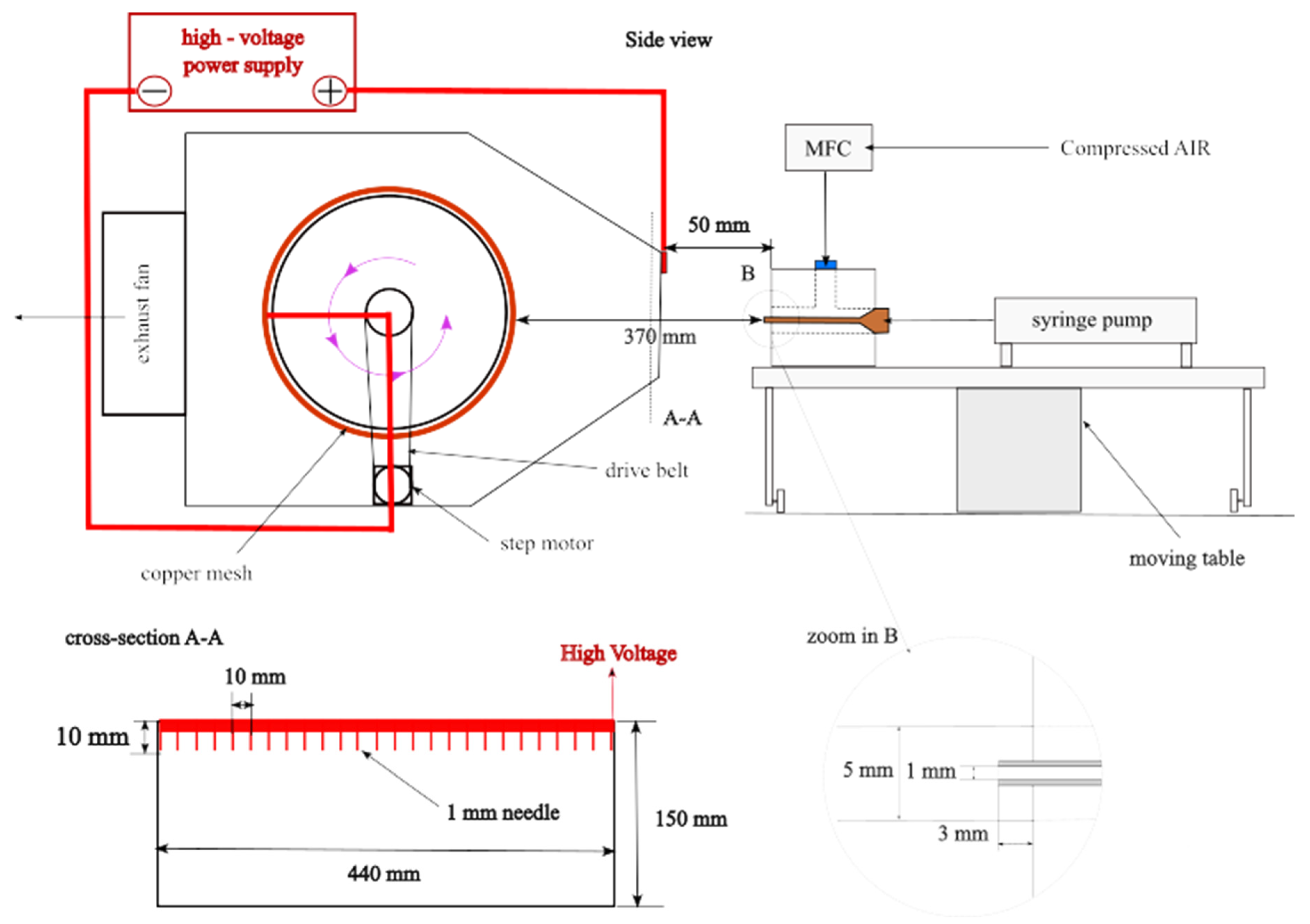
The apparatus for fiber production and electrostatic charging utilized the conventional solution blow spinning (SBS) technique. The research set-up consisted of the following elements: a syringe pump (Legato270, KDScientific, Holliston, MA, USA) equipped with a 60 mL syringe, a compressed air supply system, a mass flow controller (SFC5500–200 slm, Sensirion, Zurich, Switzerland), a collector, and coaxial nozzles with an internal diameter of 1 mm and an external diameter of 5 mm. A detailed description of the research set-up can be found in our previous works [
13]. The system was modified with an advanced fiber-forming head, which was continuously fed with a polylactic acid (PLA) solution via a precision-controlled syringe pump. This head was mounted on a linear actuator that facilitated controlled reciprocating movement. The head-to-collector distance was precisely set to 37 cm. The collector itself was a grounded, copper mesh drum housed in a ventilated enclosure, equipped with an exhaust fan for effective airflow management. At a distance of 5 cm from the nozzle, an array of 44 uniformly spaced needles, each 1 cm in length and separated by 1 cm, were positioned. This needle array was connected to a high-voltage power supply, delivering a stable direct current of 13 kV to induce the necessary electrostatic forces for fiber formation and deposition. The scheme of the research system is shown in
Figure 1. Blowing was carried out at an airflow rate of 200 L/min and a 0.5 mL/min polymer flow. The blowing time was 40 min. A minimum of three fibrous structures were created for each tested additive, concentration, and current condition.
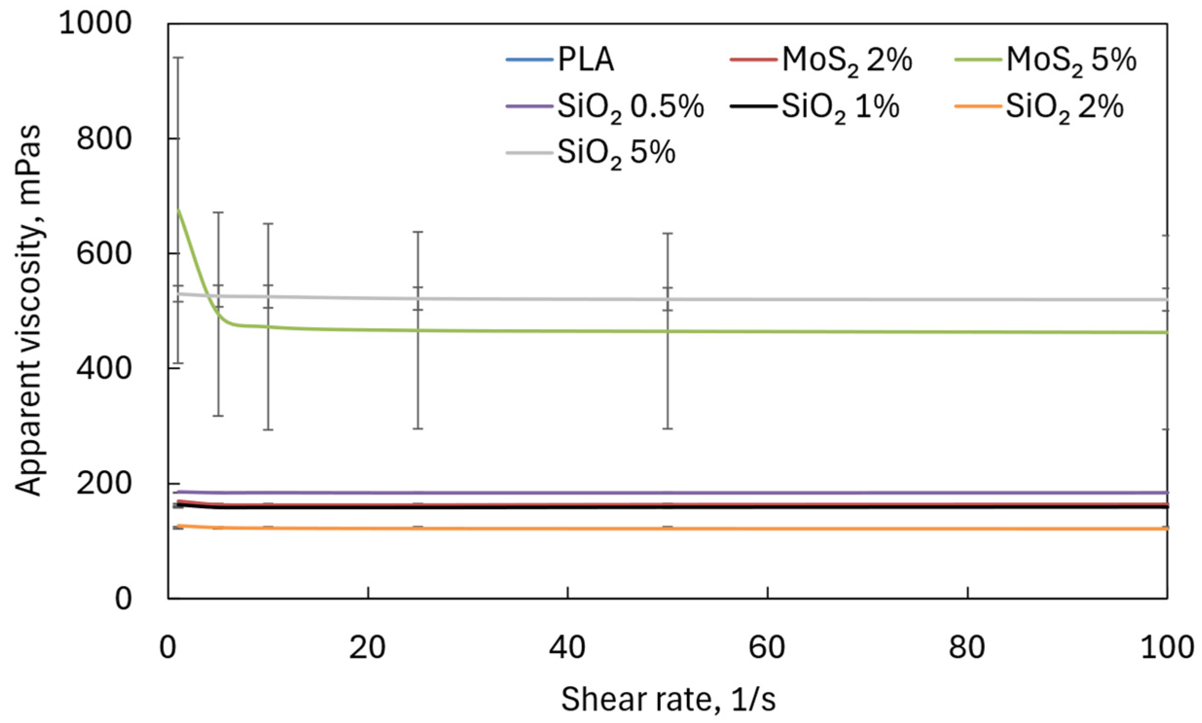
2.2. Viscosity Measurement
The apparent viscosity of the PLA solution and PLA with additives was determined using an oscillating rheometer (MCR 102, Anthon Paar, Vienna, Austria) equipped with a Peltier system and an attachment limiting the evaporation of solvents in a plate–plate system (50 mm). The test was carried out at a temperature of 22 °C. Each solution was tested at least four times, and the results presented are the average value.
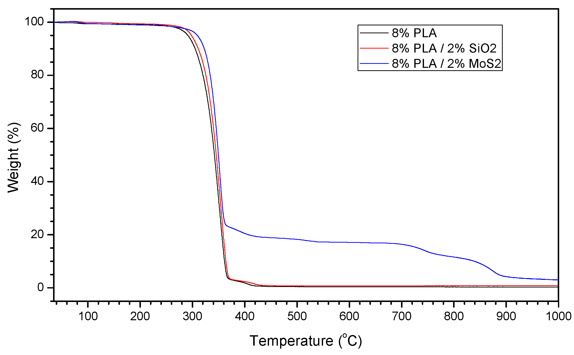
2.3. TGA Analysis
Thermogravimetric analysis (TGA) measurements were performed using a TGA/DSC 3+ system (Mettler Toledo, Greifensee, Switzerland). The analysis was performed within a temperature range of 30–1000 °C, at a heating rate of 5 °C/min·, under a synthetic air flux of 60 mL/min (≥99.999%, Multax, Zielonki-Parcela, Poland) to provide an oxidizing atmosphere for the analysis. An aluminum sample holder was used for the measurements.
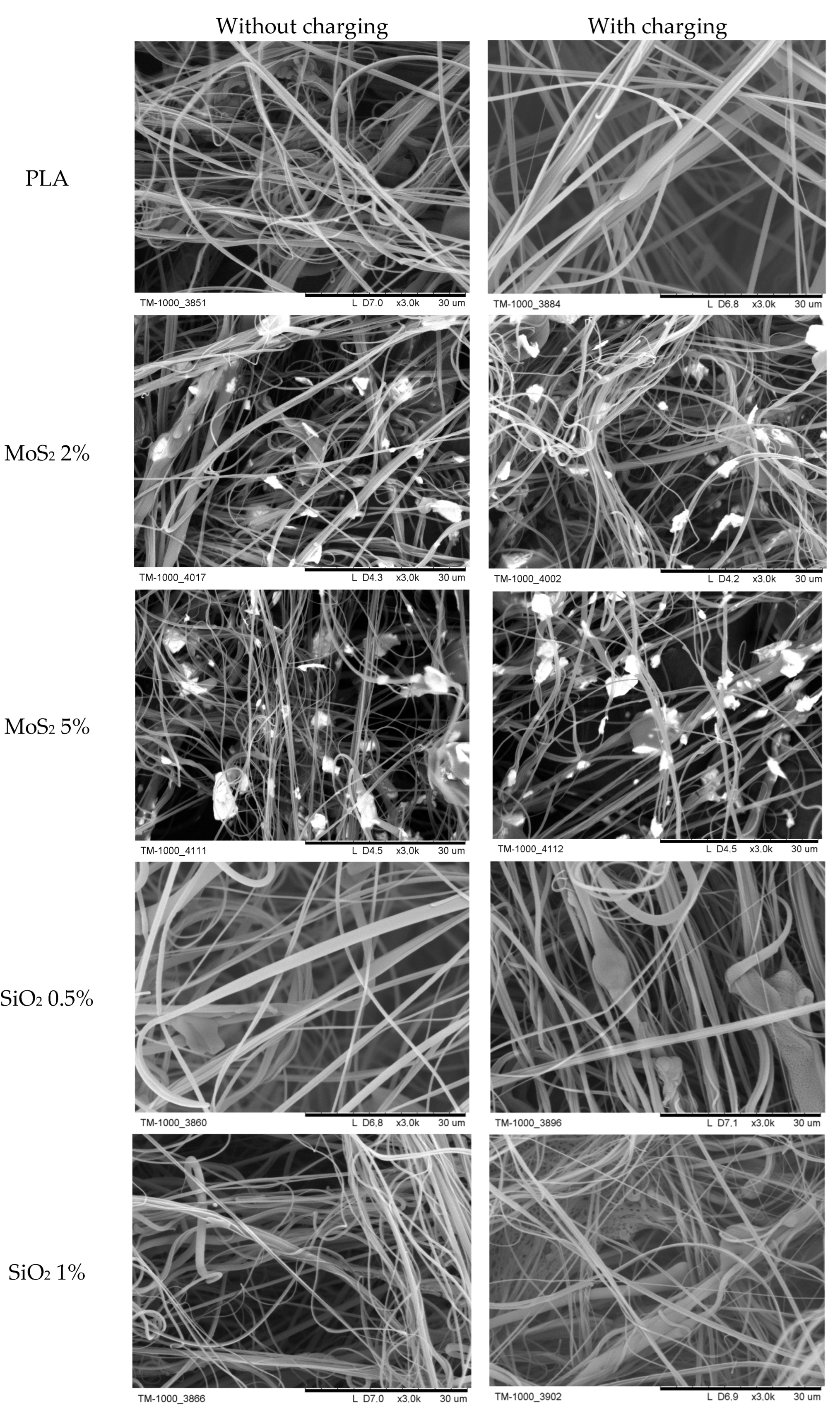
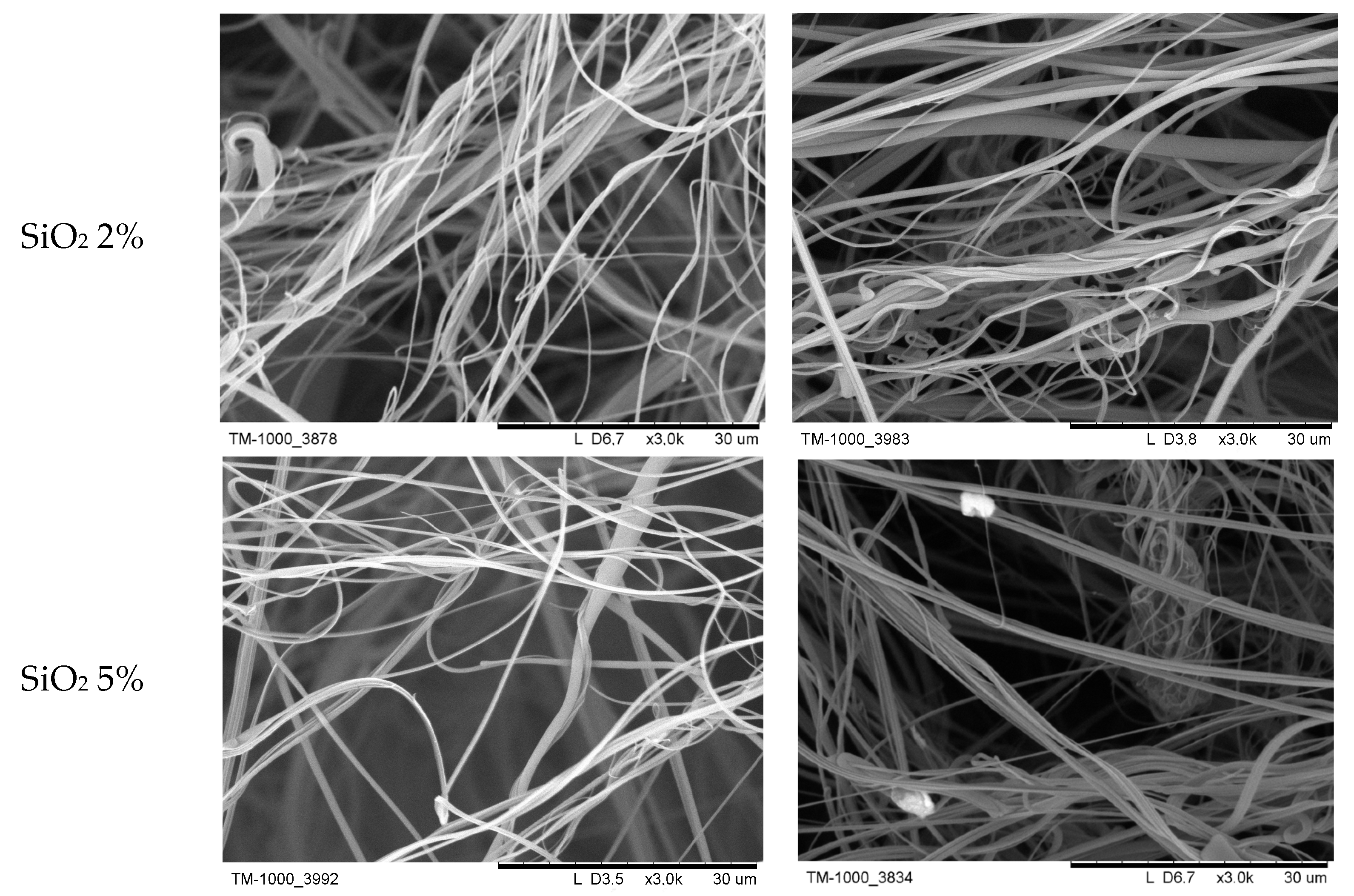
2.4. Fiber Morphology
The morphology of the fibers was determined based on photos from a scanning electron microscope (TM-1000, Hitachi, Tokyo, Japan). Before taking the picture, the fibers were sputtered with a 25 nm layer of gold (K550X EMITECH Quorum, East Sussex, UK). To determine the fiber size distribution and the average fiber diameter, approximately 100 fibers were analyzed.
The produced fibers were also characterized in terms of the porosity of the entire layer and its thickness. The thickness of the produced fiber layer was measured using an optical microscope (PCE-MM, PCE Instruments, Sosnowiec, Poland). The porosity (
α) of the fiber layer was determined based on the mass of deposited fibers (
m), the measured thickness of the fiber layer (
L), the collector area (
A = 871.5 cm
2), and the density of PLA (
ρ = 1.24 g/cm
3), according to the following relationship:
2.5. Experimental Filtration Efficiency and Stability Test
The impact of adding silicon oxide (SiO2) and molybdenum disulfide (MoS2) particles to PLA on the amount of charge accumulated during the production process was evaluated by assessing the filtration efficiency. The filtration efficiency of the materials in their initial state was analyzed using the Palas MFP 2000 system (Palas GmbH, Karlsruhe, Germany). The primary parameters considered during the design of the filtration materials, specifically filtration efficiency and pressure drop, were evaluated at the beginning of the process.
In the filtration experiments, Arizona Fine Test Dust ISO 12103-1 [
27], a polydisperse silica-based test dust (Powder Technology Incorporated, Arden Hills, MN, USA), was used. This dust consists of particles with diameters ranging from 0.2 to 16 μm, with the most common particle sizes falling between 0.35 and 0.45 μm.
The experimental set-up MFP 2000 included the following equipment: a piston-brush particle generator (RBG 1000, Palas GmbH, Karlsruhe, Germany), a pneumatic filter holder, an optical particle counter (PCS 2010, Palas GmbH, Karlsruhe, Germany), a charge neutralizer (CD 2000, Palas GmbH, Karlsruhe, Germany), and a vacuum pump (ASP 2000, Palas GmbH, Karlsruhe, Germany) to collect solid aerosol samples for analysis. Clean air was drawn into a pressurized vessel, where it was filtered and then split into two streams: one directed to the aerosol generator and the other to a mass flow controller. The rotating brush in the generator ensured the uniform dispersion of dust particles within the airstream. Aerosol particles that became electrostatically charged while passing through the brush generator, piston, and connecting tubes were neutralized by mixing the aerosol stream with bipolarly ionized gas. This step was essential to ensure that any electrical charge measured originated exclusively from the intentionally charged fibers in the filter material. The neutralized aerosol was then introduced into a column containing the tested filter material, secured within a pneumatic holder with a circular cross-section of 14 cm in diameter, resulting in an effective test area of approximately 150 cm2. The pressure drop across the filter was continuously monitored using a digital differential manometer. Simultaneously, the particle concentration and size distribution in the airflow were measured using an optical particle counter, with equal aerosol samples drawn in by the vacuum pump.
For each tested filter material, both charged and uncharged, three separate measurements of the initial filtration efficiency and pressure drop were conducted. These repeated measurements confirmed the consistency and repeatability of the results. The filtration efficiency values presented in this study represent the average of three samples for each material. All tests were conducted under identical process conditions, including an aerosol flow velocity of 0.2 m/s and a consistent silica particle concentration.
Due to the configuration of the testing apparatus, which was equipped with only one sampling probe and one particle counter, the measurement procedure was as follows. First, the particle concentration in the incoming aerosol stream was measured. Then, the filter material was placed in the pneumatic holder, and the number of particles downstream of the filter was recorded. To verify the stability of the particle generator, an additional measurement of the upstream particle concentration was performed after the filter was removed from the holder. Each measurement lasted for 40 s, and the results confirmed the stability of the silica particle source throughout the tests.
Before conducting the main filtration efficiency tests, an initial investigation was carried out to determine the distribution and adhesion of the added particles within the PLA fibers. Specifically, the aim was to establish whether the particles were encapsulated within the fibers or situated on their surface, and, if on the surface, whether they were securely attached or prone to being re-entrained by the airflow. To address this, a stream of clean air (without any particles) at varying flow velocities was passed through the filter material. The optical particle counter continuously monitored for any particles downstream of the filter. If particles were detected in the air behind the filter during this test, it would mean that the SiO2 and MoS2 particles were not permanently attached to the fiber and detached from it as the air flowed through the filter. Thus, the filter could not be used in research. The results of this experiment demonstrated that the added particles of SiO2 and MoS2 remained firmly attached to the surface of the PLA fibers during the airflow.
2.6. Theoretical Filtration Efficiency
The theoretical initial filter efficiency was calculated based on classical filtration theory, summarized by Podgórski [
28] as follows:
where
L is the filter media thickness. The filter coefficient,
λ, is related to single-fiber efficiency,
E, as follows:
where
α is the fiber’s packing density, and
df is the fiber diameter. The single-fiber efficiency (defined as a ratio of the flux of particles depositing onto the fiber to the flux of particles passing a surface, being the projection of the fiber onto a plane perpendicular to the direction of mean motion) was calculated assuming that the deposition efficiency due to deterministic mechanisms,
Edet (inertial impaction, interception, sedimentation, and electrostatic forces), and stochastic mechanism (Brownian diffusion),
Ediff, was independent:
Particle collection by interception occurs when a particle follows a gas streamline that happens to come within a particle radius from the surface of a fiber. The particle hits the fiber and is captured due to its finite size. The single-fiber deposition efficiency due to interception depends on the dimensionless parameter
R, defined as follows:
where
dp is the aerosol particle diameter.
The single-fiber efficiency due to interception,
ER, was given by Lee and Ramamurthi [
29] as follows:
where the Kuwabara factor,
Ku, is defined as
Inertial impaction occurs when the particle, because of its inertia, is unable to adjust quickly to the abruptly changing streamlines near the fiber and crosses those streamlines to hit the fiber. The parameter that governs this mechanism is Stokes number,
Stk:
where
μ is the fluid viscosity,
ρp is the density of the particle sand, and
U is the superficial velocity of flow.
The Cunningham slip correction factor,
Cc, which corrects for reduced drag force on particles in gas flow, is calculated as follows [
30]:
where
λg is the mean free path of gas molecules.
The single-fiber efficiency for inertia,
EI, is given by Stenhouse [
31]:
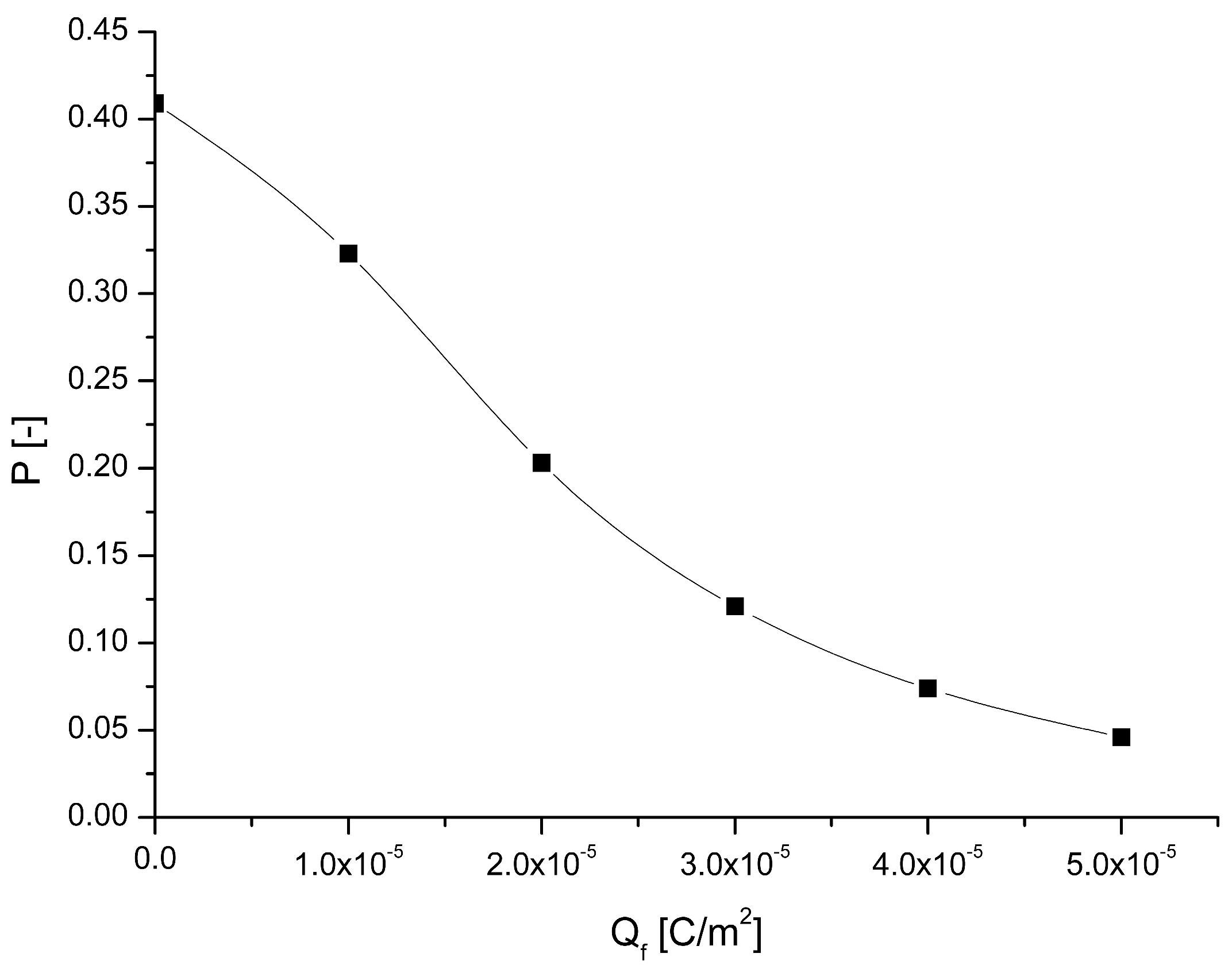
Finally, the deposition efficiency due to inducted forces,
Ein, [
32] is taken into account:
The inducted force parameter, Kin, is given by the following:
where
Qf is the charge density on fiber,
ε0 is the dielectric constant of vacuum, and
εf and
εp are the relative dielectric constants of fibers and particles, respectively.
4. Discussion
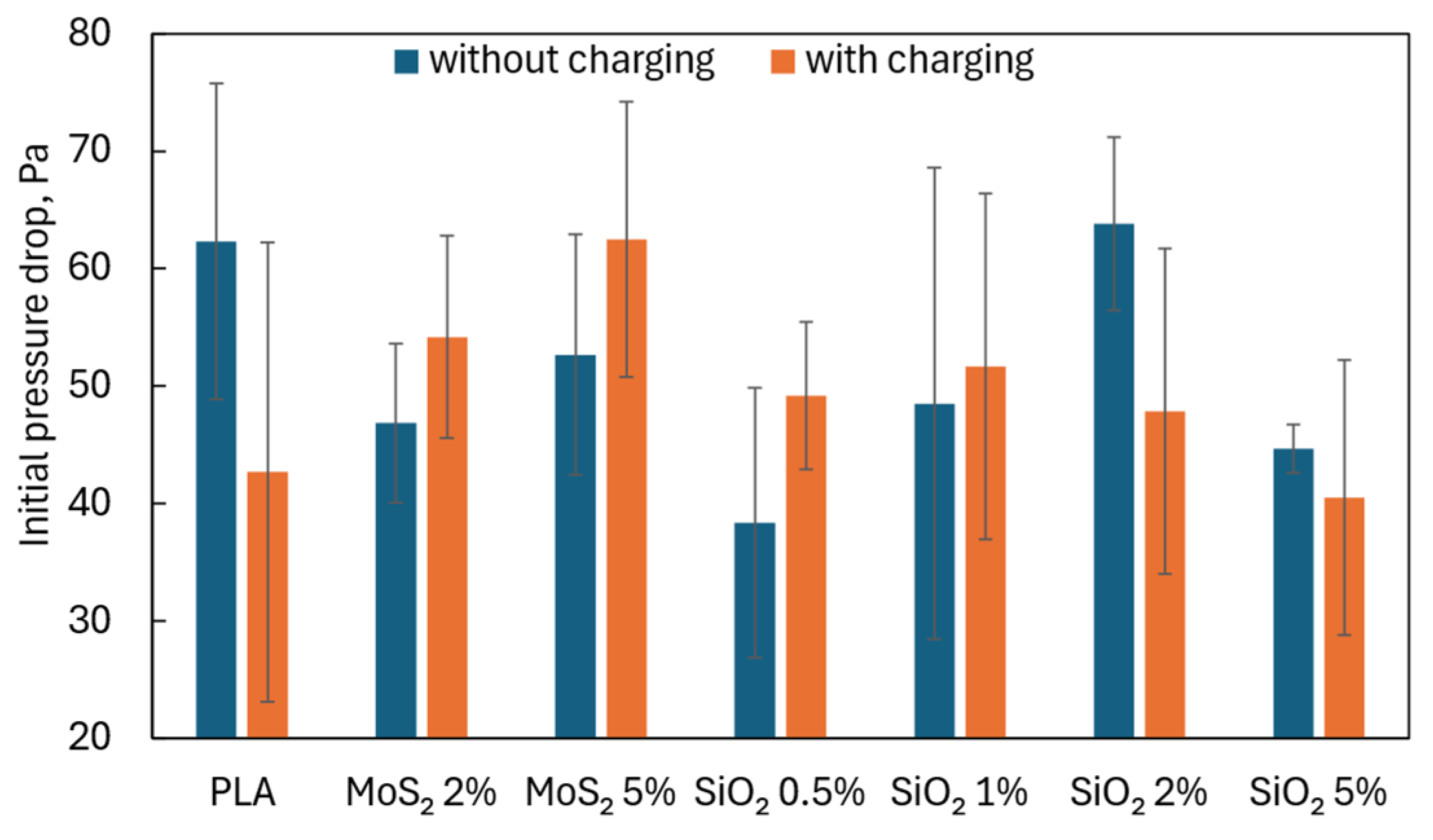
A high filtration efficiency is desirable, but often, if achieved due to reduced porosity, increased thickness of the filtration structure, and a significant reduction in the average fiber diameter, it is accompanied by a high pressure drop when air flows through the tested structure. The fibrous layers containing additives produced by us were characterized by a pressure drop that did not exceed the pressure drop for fibers made of pure PLA (
Figure 10). Higher pressure drops were recorded for fibers with the addition of MoS
2 than for fibers with the addition of SiO
2.
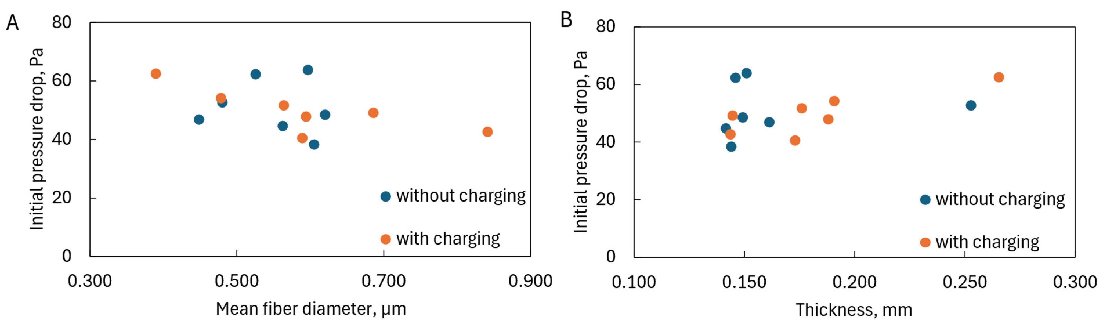
The pressure drop increased with decreasing average fiber diameters (
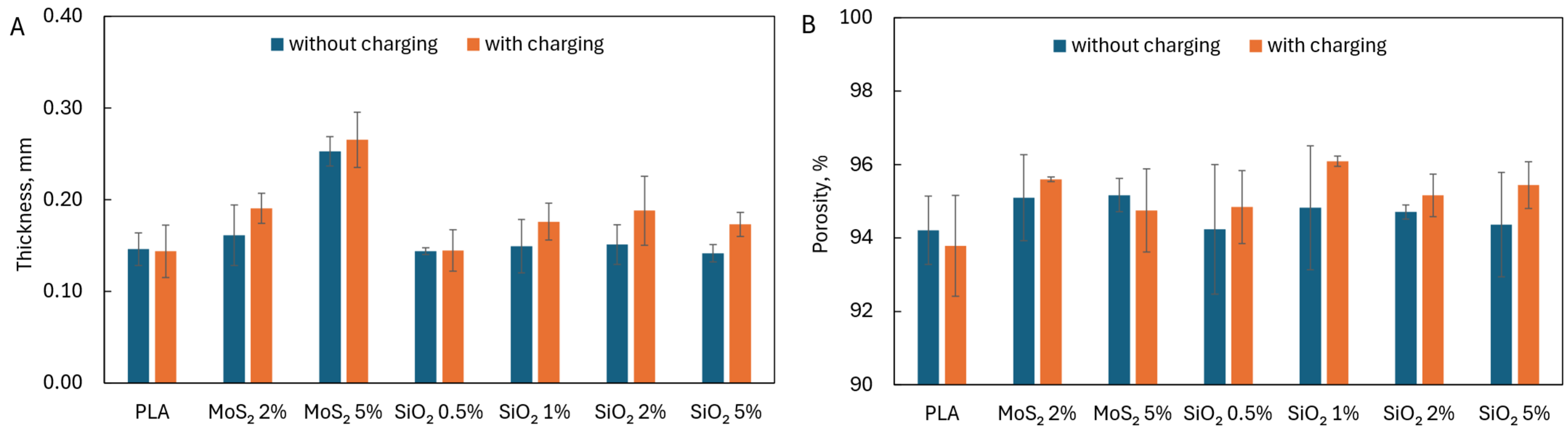
Figure 11A) but was not affected by the presence of charges on the fiber surface. However, due to the similar porosity of the structures produced, the pressure drop did not change with their thickness (
Figure 11B).
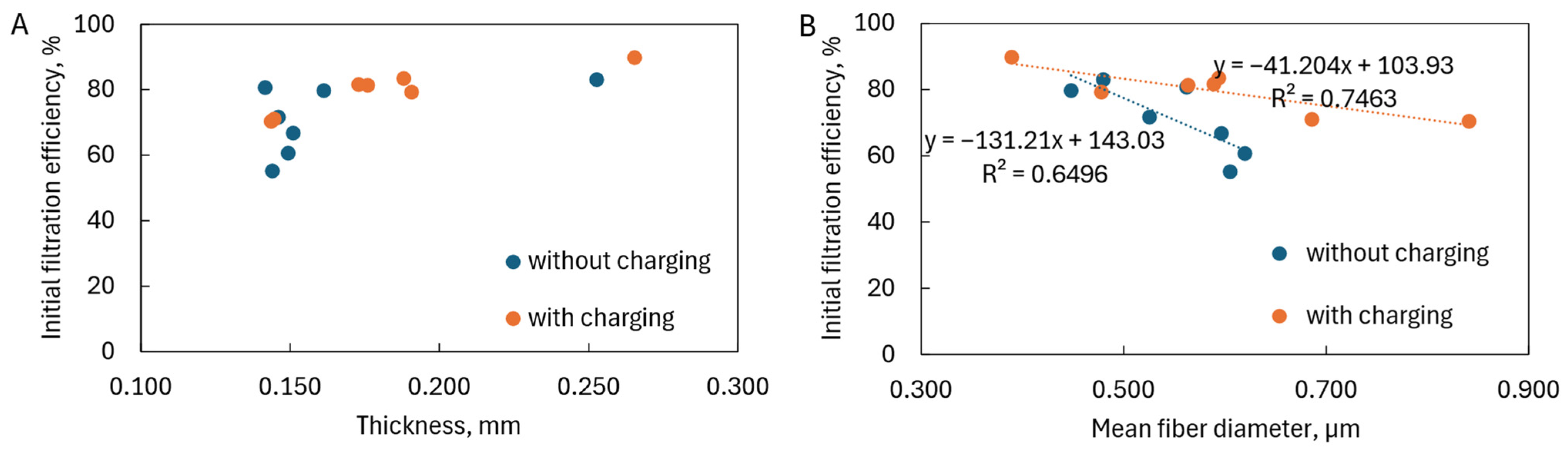
The thickness of the fiber layers also did not affect the initial filtration efficiency (
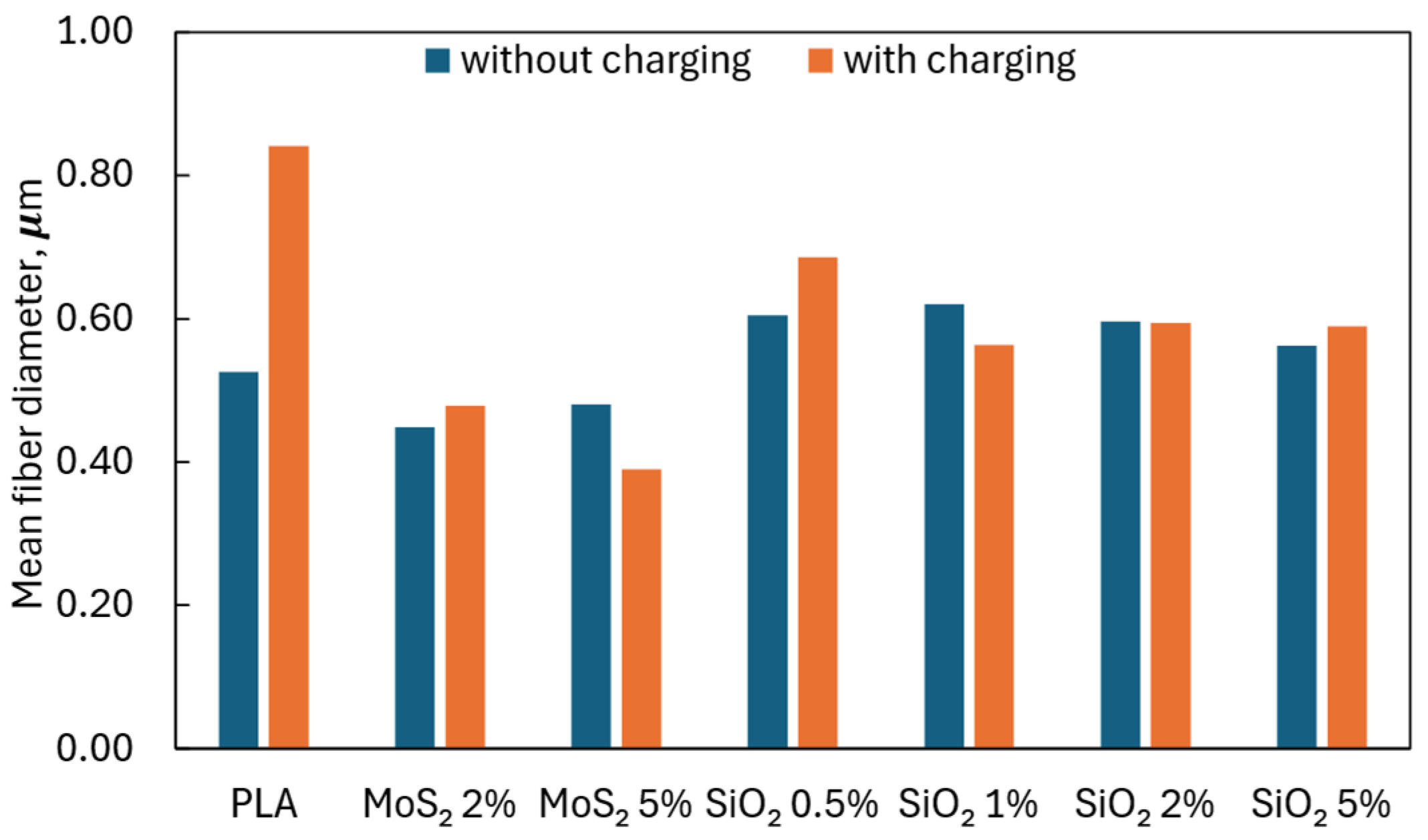
Figure 12A). According to filtration theory, it was influenced by the average fiber diameter: the thinner the fiber, the higher the filtration efficiency (
Figure 12B). However, it was visible that, in the case of charged fibers, the filtration efficiency increased slower with a decrease in fiber diameter than in the case of uncharged fibers. The small angle of inclination of the fitting lines for electrets indicated that electrostatic interactions had a much more significant impact on filtration efficiency than the average fiber diameter. Increasing the average fiber diameter, which reduced the filtration efficiency, was compensated in electrets by electrostatic interactions, increasing the deposition of particles on the fibers. However, for filters without charging, the angle of inclination of the curve was significant, and even a small change in the average fiber diameter caused a substantial reduction in filtration efficiency. Unfavorable fitting lines and corresponding low R
2 values were characteristic features of solution blowing, a susceptible and multi-parameter process.
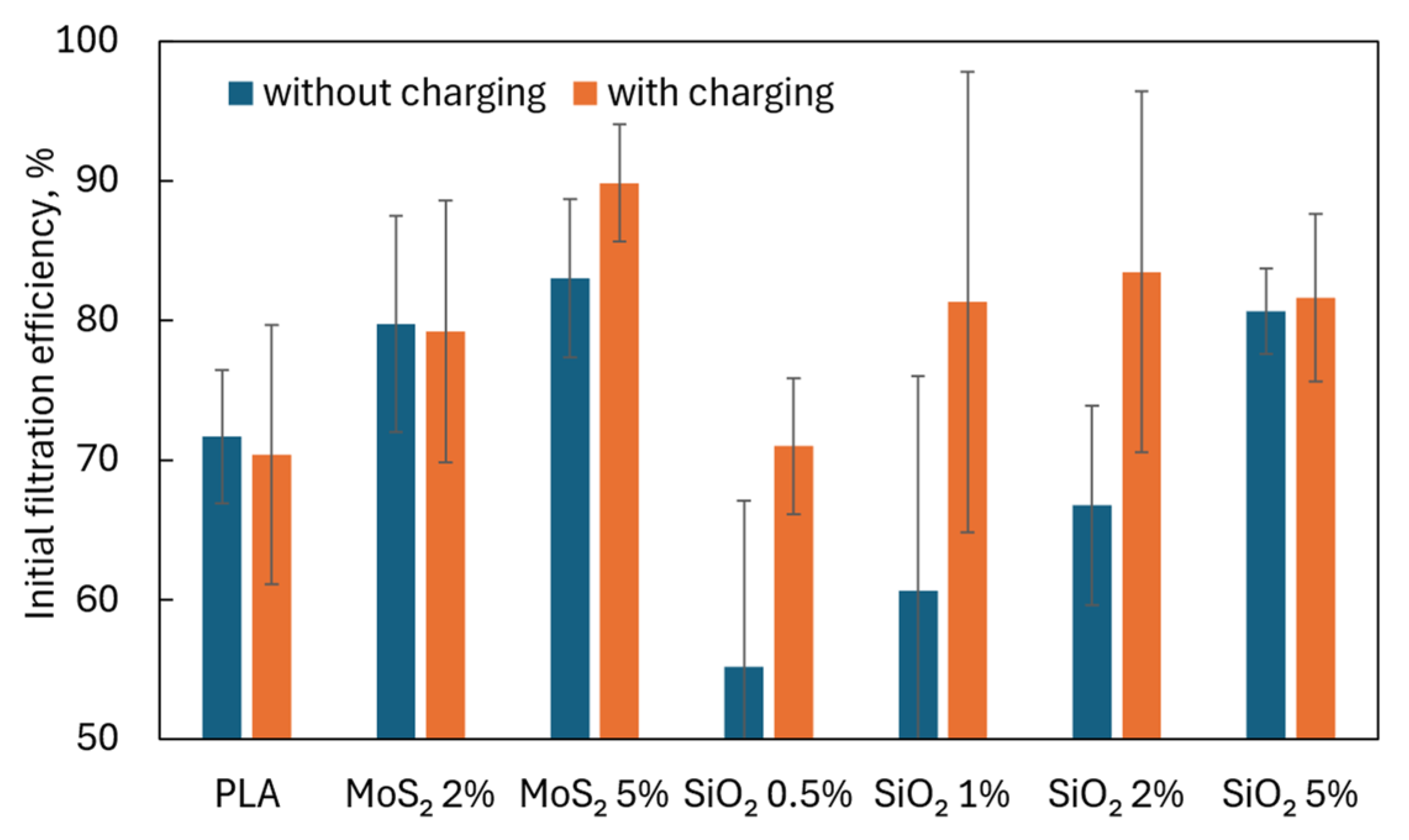
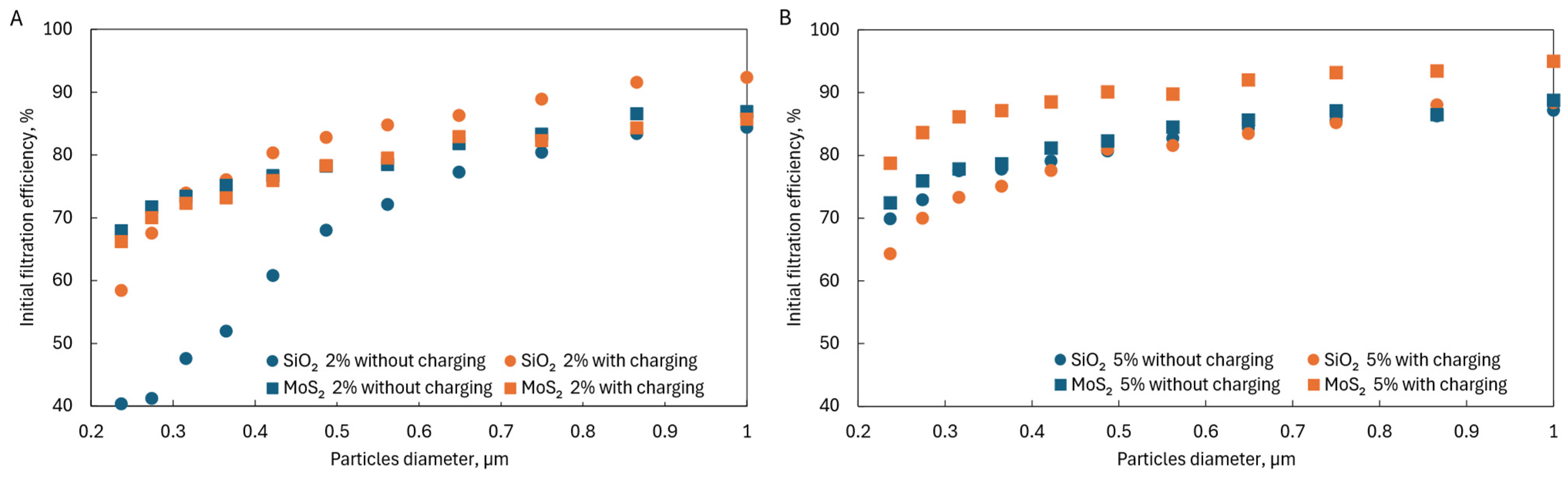
The tests showed that adding MoS
2 and SiO
2 affected the filtration efficiency of particles in the range of 0.2–1 µm. In the case of SiO
2, there were optimal concentrations above which no significant improvement in filtration efficiency was observed; in the case of MoS
2, there were too few concentrations analyzed to identify such a relationship. When comparing both additives at the same concentrations, it could be seen that higher filtration efficiencies were achieved for MoS
2 than for SiO
2 at the same concentrations (
Figure 13A,B), which may indicate that MoS
2 is a better additive.
The addition of MoS
2 to PLA fibers resulted in a higher filtration efficiency compared to fibers containing SiO
2. This could be attributed to several key properties of MoS
2: (i) Among these were its layered structure and high surface area-to-volume ratio. MoS
2 has a characteristic two-dimensional structure, which provides a large specific surface area. This feature enhances filtration efficiency by improving particle capture. Studies have shown that layered materials, such as MoS
2, can significantly improve filtration properties due to their increased active surface area [
34]. (ii) MoS
2 addition to the PLA solution resulted in thinner fibers. The layered structure of MoS
2 allowed its particles to align parallel to the direction of the stretching flow, potentially reducing flow resistance and facilitating the formation of thinner fibers, which increased the active surface area for the filtration process [
35]. In contrast, SiO
2 has a three-dimensional (3D) and often spherical or irregularly shaped structure, which can lead to an increased solution viscosity and the formation of thicker fibers. Additionally, MoS
2, due to its 2D structure, exhibited minimal agglomeration and better dispersion within the polymer solution, allowing for a lower viscosity even at higher additive concentrations. In contrast, SiO
2, especially in nano form, tends to aggregate within solutions, which can increase viscosity and hinder the stretching of the flow during fiber formation. (iii) Another important aspect were electrostatic interactions and polarization in an electric field. As a semiconductor, MoS
2 can undergo polarization in the presence of an electric field, leading to localized changes in charge distribution. These dynamic interactions can enhance the attraction and retention of contaminant particles, thereby increasing filtration efficiency [
36]. (iv) Finally, increased electron mobility and surface conductivity were also observed. MoS
2 exhibited high electron mobility, allowing for a better response to the electric field and the formation of localized electrostatic effects on the fiber surface. This facilitated a more effective attraction of contaminant particles. Studies on composites containing MoS
2 have demonstrated that its conductive properties can improve filtration efficiency [
37].
In summary, the higher filtration efficiency of PLA fibers with MoS
2 addition resulted from the synergy of its unique structural and electrostatic properties, making it a more effective additive compared to SiO
2. In addition, MoS
2 also has increased sorption properties compared to oil [
38], so using it for fiber production can grant said fibers additional desirable properties.


 ,
, 


