
Enhancing Mid-Term Strength and Microstructure of Fly Ash–Cement Paste Backfill with Silica Fume for Continuous Mining and Backfilling Operations
Abstract
1. Introduction
2. Materials and Methods
2.1. Experimental Materials
2.1.1. Silica Fume
2.1.2. Cement
2.1.3. Gangue
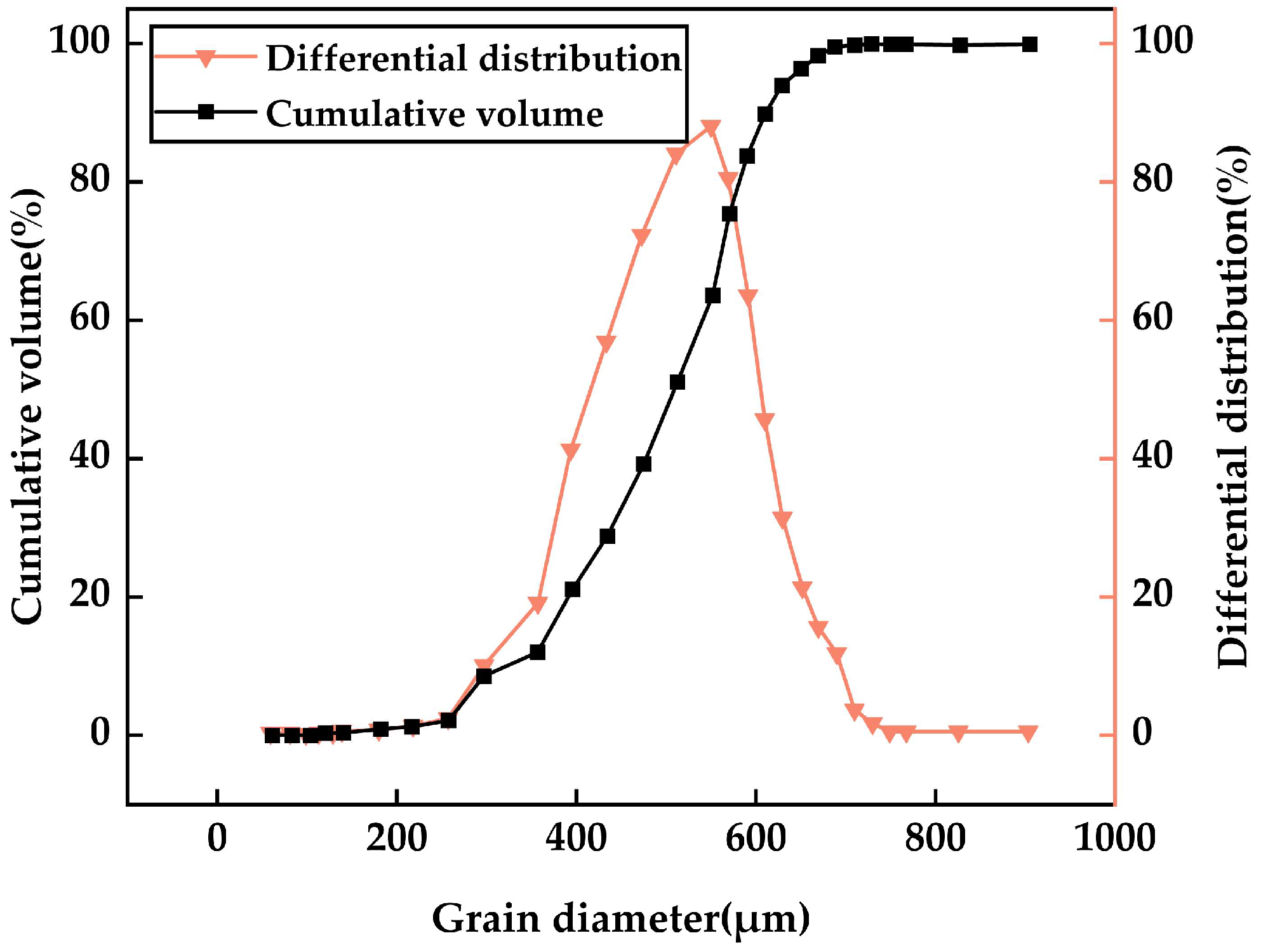
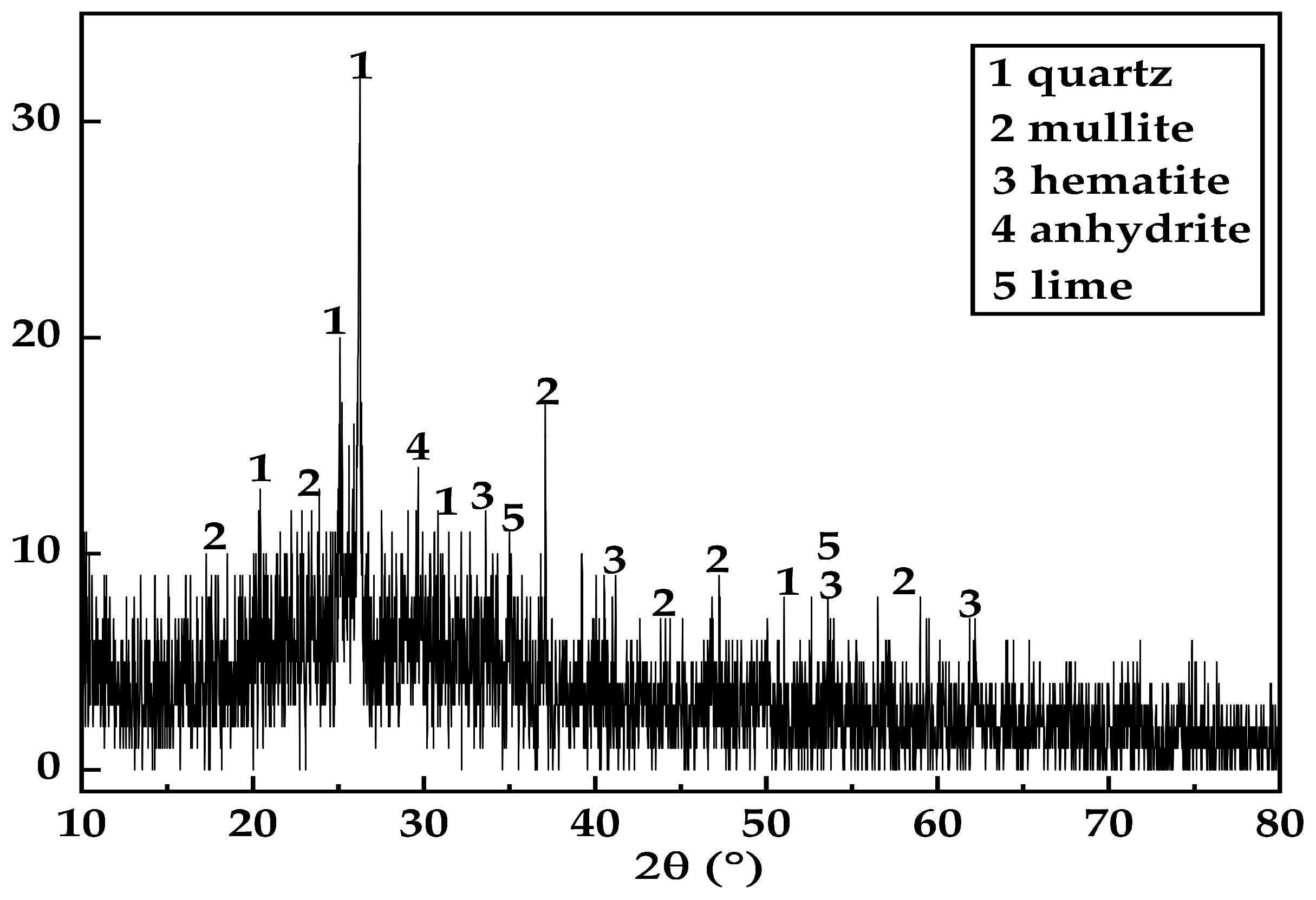
2.1.4. Fly Ash
2.2. Sample Preparation
2.3. Experimental Methods
2.3.1. Setting Time Test
2.3.2. Analysis of Liquidity
2.3.3. Uniaxial Compressive Strength Test
2.3.4. Microstructure Analysis
3. Results and Discussion
3.1. Effect of SF on SFCP Setting Time
3.2. Analysis of the Influence of SF on SFCP Liquidity
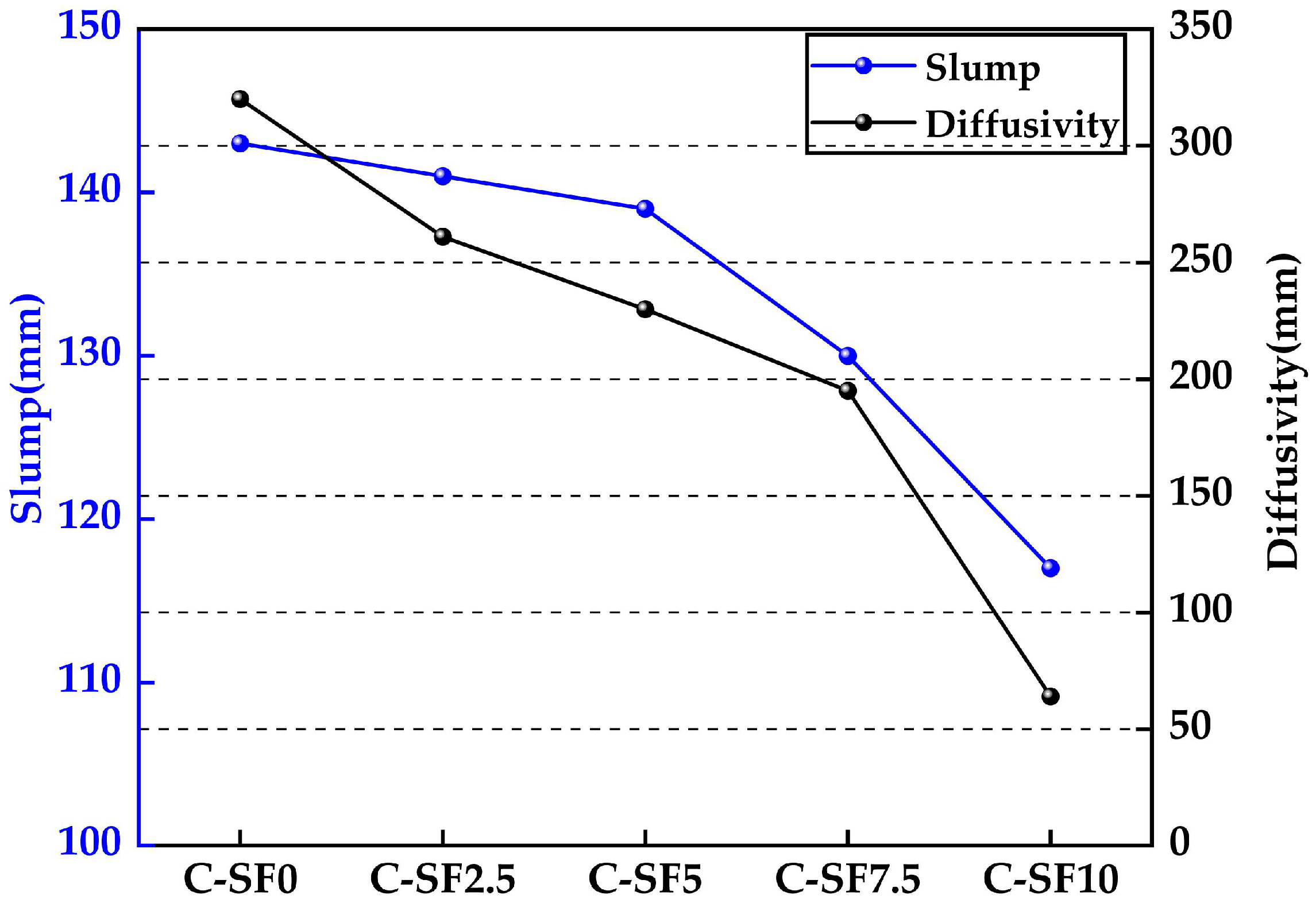
3.2.1. Analysis of the Effect of SF on the Diffusion and Slump of SFCP
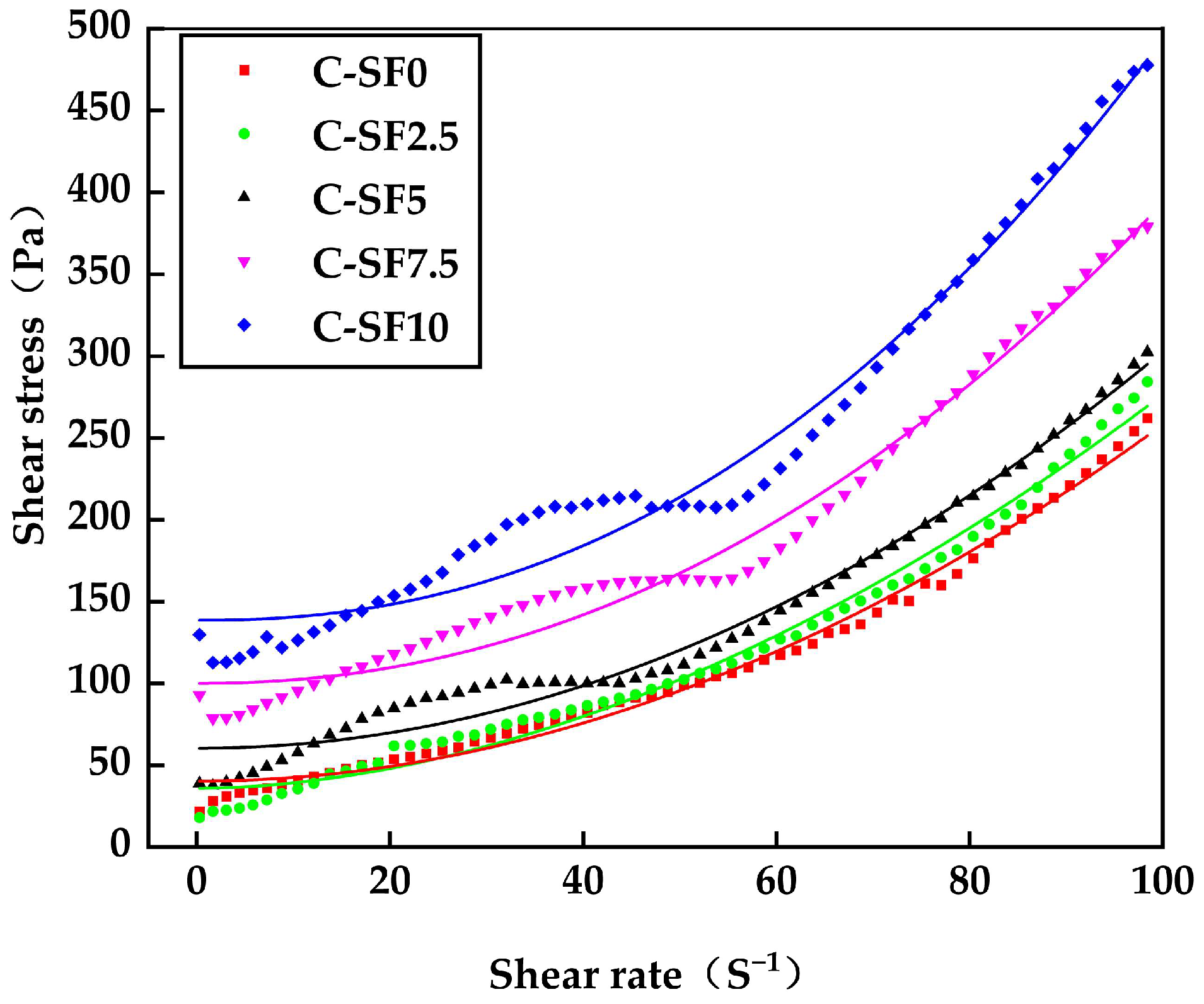
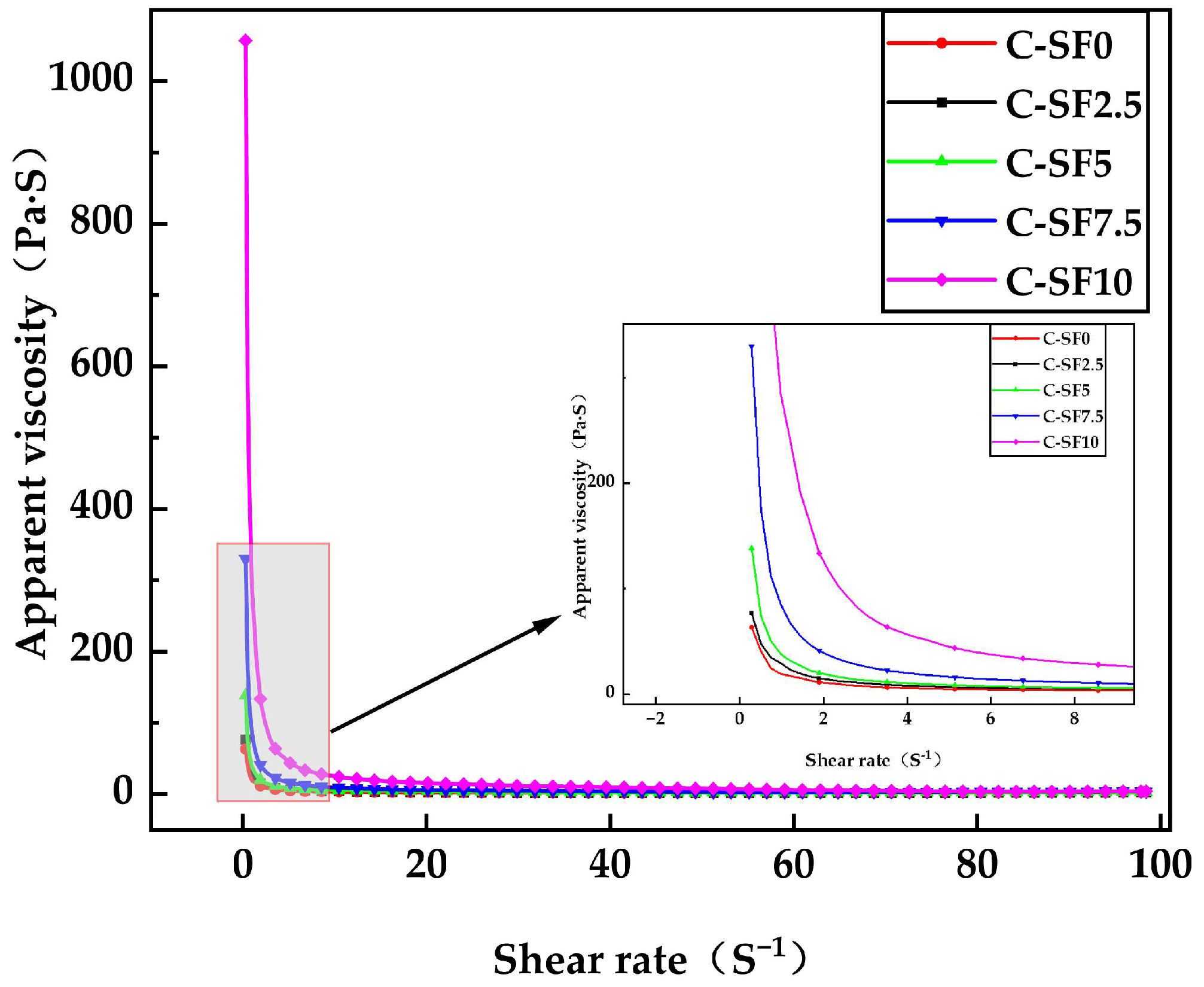
3.2.2. Effect of SF on Rheological Properties of SFCP
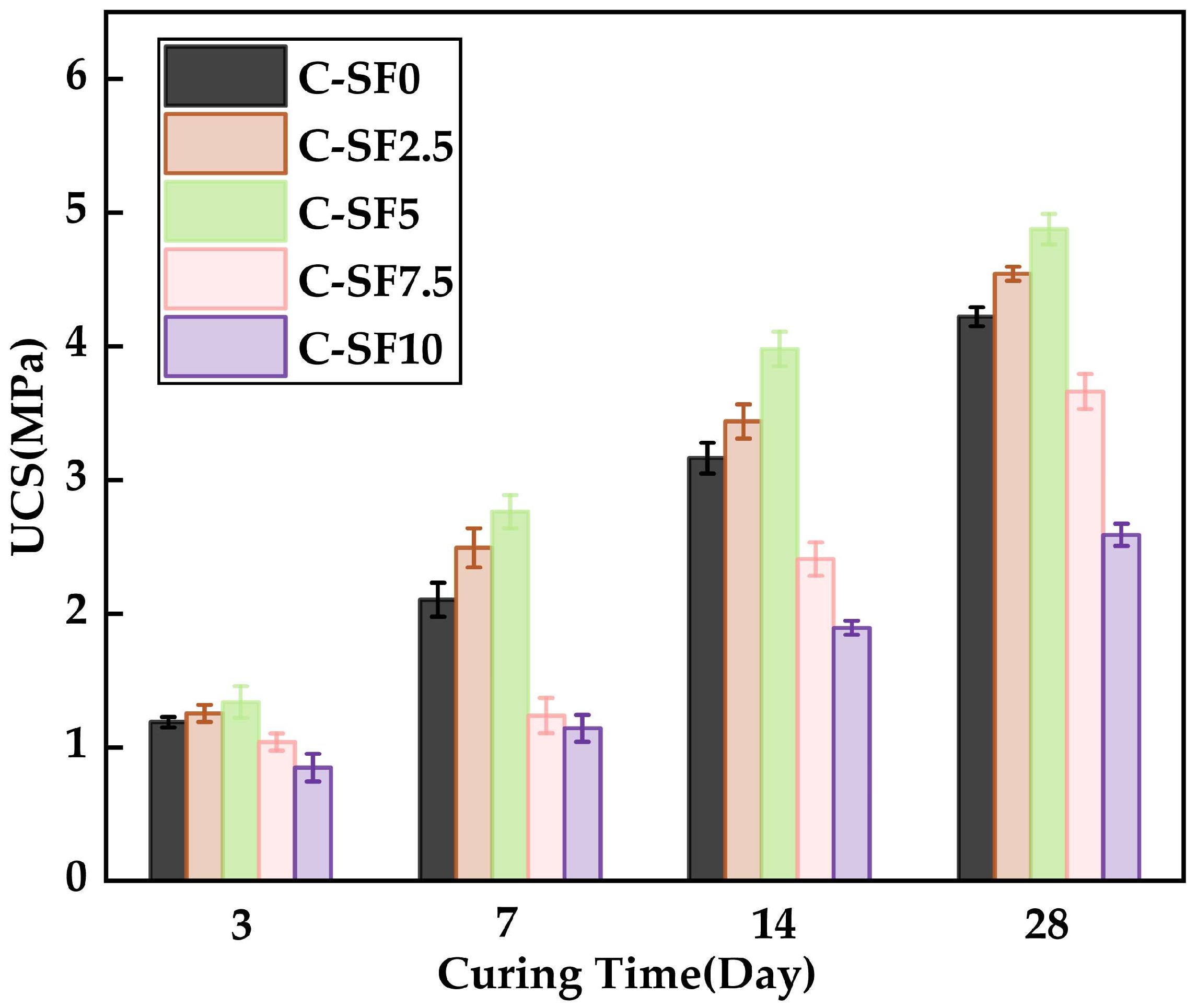
3.3. Effect of SF on Uniaxial Compressive Strength of SFCP
3.4. Microstructure Analysis of SFCP
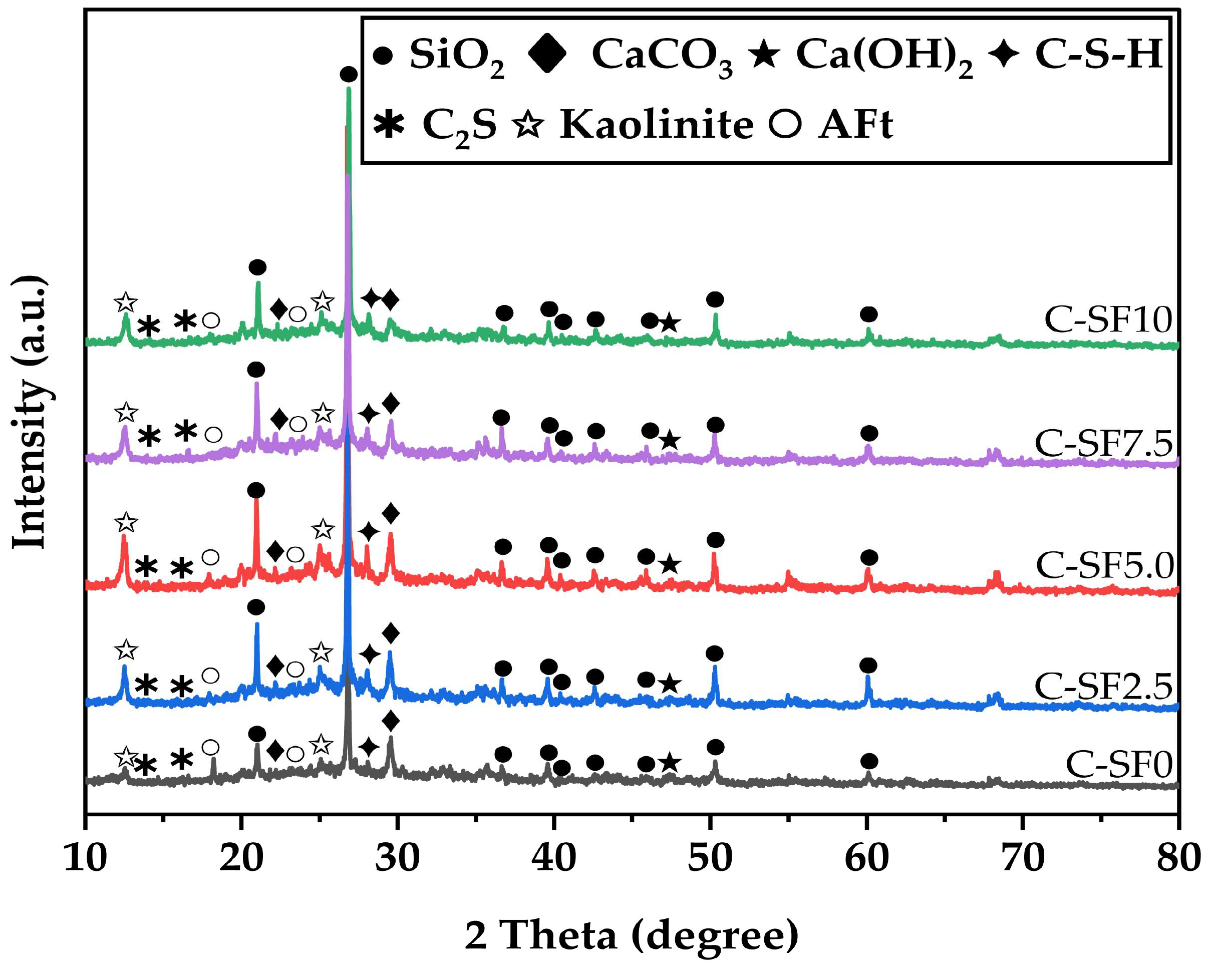
3.4.1. X-Ray Powder Diffractometer Image Analysis of SFCP
3.4.2. Scanning Electron Microscope Image Analysis of SFCP
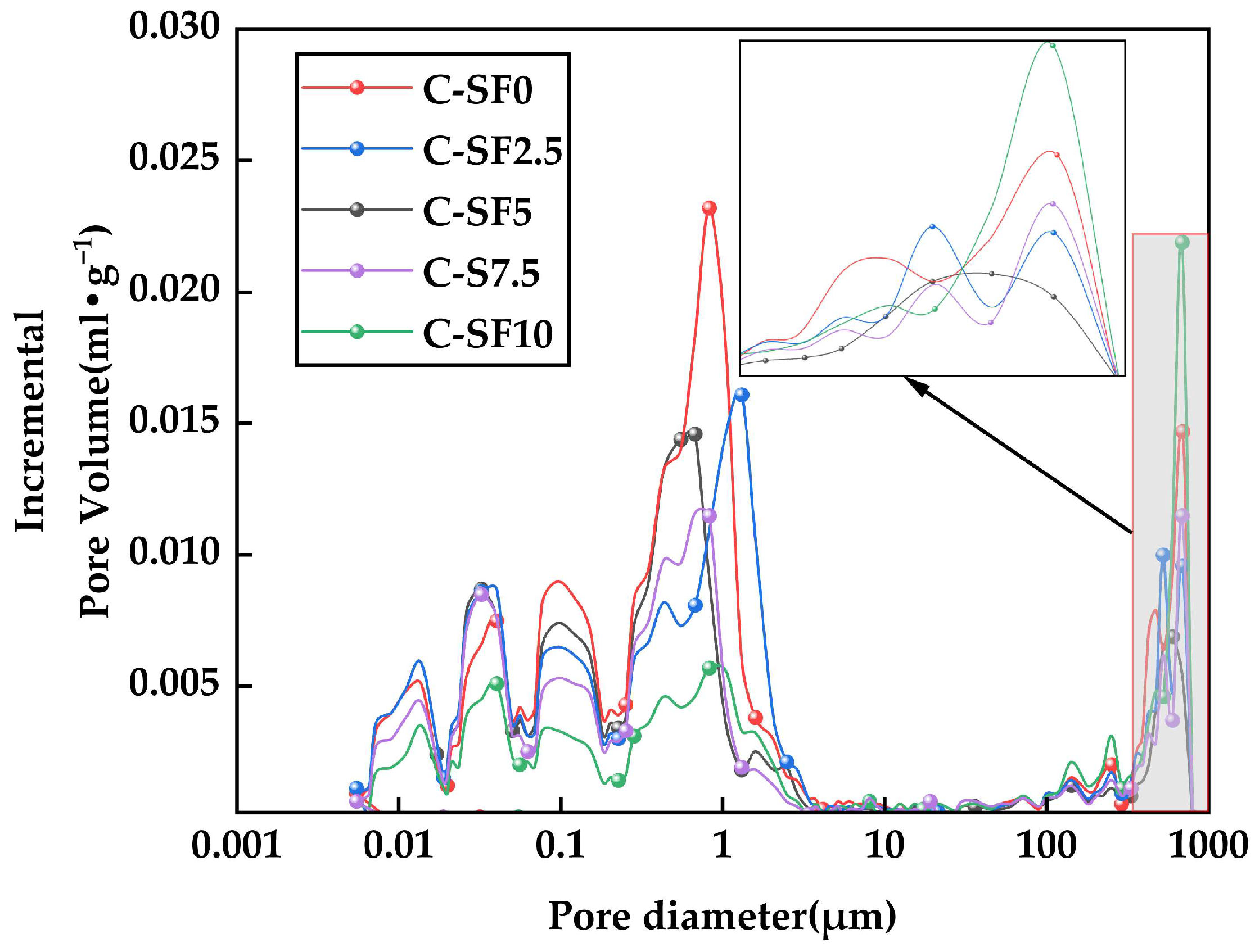
3.4.3. Image Analysis of Aperture Distribution of SFCP
4. Conclusions
- The incorporation of silica fume had a significant impact on the setting time of the slurry. When the silica fume content was 5%, the initial and final setting times of the slurry were 900 min and 980 min, respectively, representing reductions of 6.25% and 7.5% compared to the control group. However, when the silica fume content exceeded 5%, the setting time increased significantly, which is detrimental to improving construction efficiency.
- As the silica fume content increased, the flowability of the slurry gradually decreased. Notably, when the silica fume content exceeded 7.5%, the flowability dropped sharply, with the spread decreasing by 67% and the slump decreasing by 16% compared to those for the control group, though it still met the requirements for pipeline transportation. A moderate incorporation of silica fume (≤5%) can enhance material performance while maintaining basic flowability.
- The silica fume content had a significant effect on the uniaxial compressive strength (UCS) of the slurry. At a curing age of 14 days, the UCS reached 3.98 MPa when the silica fume content was 5%, representing a 25% increase compared to the control group, indicating optimal medium-term strength. However, when the silica fume content exceeded 5%, the UCS decreased significantly, with a maximum reduction of 41% due to particle agglomeration and restricted hydration reactions. A moderate silica fume content promotes the formation of C-S-H gel through secondary hydration reactions, enhancing structural strength, while excessive silica fume disrupts this balance, leading to a strength reduction.
- The microstructural analysis revealed that the addition of an appropriate amount of silica fume significantly improved the slurry’s density, reduced the number and distribution of micropores, and optimized the pore structure. At a silica fume content of 5%, the formation of C-S-H gel was maximized, and the pore structure was most optimized. However, high silica fume contents (≥7.5%) resulted in particle agglomeration and the formation of large pores, which weakened the overall strength and durability of the material. This indicates that the silica fume content must be carefully controlled to balance its positive and negative effects.
- Considering the effects of silica fume on the setting time, flowability, compressive strength, and microstructure, the optimal silica fume content was determined to be 5%. This content maintains material flowability while significantly improving the medium-term strength and structural density. This finding provides a scientific basis for the design of backfill materials under continuous mining and backfilling conditions.
Author Contributions
Funding
Institutional Review Board Statement
Informed Consent Statement
Data Availability Statement
Conflicts of Interest
Abbreviations
| FA | Fly ash |
| SF | Silica fume |
| FCP | Fly ash cement paste |
| SFCP | Silica fume cementitious paste |
| CMCB | Continuous mining and continuous backfilling |
| C-SF | The proportion of cement replaced by an equivalent amount of silica fume |
| τ0 | Yield stress |
| K | Rheological consistency index |
| n | Rheological flow behavior index |
| R2 | Coefficient of determination (goodness of fit) |
| UCS | Uniaxial compressive strength |
| C-S-H | Calcium silicate hydrogel |
| XRD | X-ray diffraction |
| SEM | Scanning electron microscope |
| MIP | Mercury intrusion porosimetry |
| AFt | Alumina ferrite trisulfate |
| Overall sample mean | |
| Mean of the i-th group | |
| Observation j in group i | |
| N | Total number of observations |
| k | Number of groups |
| ni | Number of observations in the i-th group |
| SSB | Sum of squares between groups |
| SSW | Sum of squares within groups |
| MSB | Mean square between groups |
| MSW | Mean square within groups |
| dfbetween | Degrees of freedom between groups |
| dfwithin | Degrees of freedom within groups |
| F | F-statistic for ANOVA |
| P | p-value for significance testing |
References
- Teng, J.W.; Qiao, Y.H.; Song, P.H. Analysis of exploration, potential reserves and high efficient utilization of coal in China. Chin. J. Geophys. 2016, 59, 4633–4653. [Google Scholar] [CrossRef]
- Cui, Z. Study on Fracture Development Law of Roof and Floor in Short Wall Filling Mining of Close Distance Coal Seam. Master’s Thesis, China University of Mining & Technology, Xuzhou, China, 2021. [Google Scholar]
- Zhang, Q.; Wang, Z.; Zhang, J.; Jiang, H.; Wang, Y.; Yang, K.; Tian, X.; Yuan, L. Integrated green mining technology of “coal mining-gangue washing-backfilling-strata control-system monitoring”—Taking Tangshan Mine as a case study. Environ. Sci. Pollut. Res. 2022, 29, 5798–5811. [Google Scholar] [CrossRef] [PubMed]
- Yang, Y.; Zhang, M.; Hu, G.; Guan, K. Simulations of goaf surface subsidence via filling control. PLoS ONE 2022, 17, e0261740. [Google Scholar] [CrossRef]
- Lin, H.; Yang, Y.; Chen, C.; Ding, C. Influence of Mining Sequence of Branch on Stope Pressure Behaviour on Continuous Mining and Continuous Backfilling. Processes 2024, 12, 442. [Google Scholar] [CrossRef]
- Xu, B.; Li, Y.; Wang, S.; Luo, H.; Lu, B. Study on the strength characteristics and failure characteristics of the composite load-bearing structure in the cemented filling field. Constr. Build. Mater. 2022, 330, 127242. [Google Scholar] [CrossRef]
- Zhu, W.; Wang, F.; Chen, S.; Yin, D.; Zhou, J.; Jie, Z.; Zou, Y. Asymmetric Deformation Mechanism of Roadway with Continuous Mining and Continuous Backfilling. Rock Mech. Rock Eng. 2024, 57, 2125–2142. [Google Scholar] [CrossRef]
- Qi, C.; Guo, L.; Wu, Y.; Zhang, Q.; Chen, Q. Stability Evaluation of Layered Backfill Considering Filling Interval, Backfill Strength and Creep Behavior. Minerals 2022, 12, 271. [Google Scholar] [CrossRef]
- Lu, B.; Li, Y.; Fang, S.; Lin, H.; Zhu, Y. Cemented Backfilling Mining Technology for Gently Inclined Coal Seams Using a Continuous Mining and Continuous Backfilling Method. Shock Vib. 2021, 2021, 6652309. [Google Scholar] [CrossRef]
- Zhang, J.; Yang, K.; He, X.; Zhao, X.; Wei, Z.; He, S. Research status of comprehensive utilization of coal-based solid waste (CSW) and key technologies of filling mining in China: A review. Sci. Total Environ. 2024, 926, 171855. [Google Scholar] [CrossRef]
- Durán-Herrera, A.; Juárez, C.A.; Valdez, P.; Bentz, D. Evaluation of sustainable high-volume fly ash concretes. Cem. Concr. Compos. 2011, 33, 39–45. [Google Scholar] [CrossRef]
- Han, P.; Zeng, N.; Oda, T.; Lin, X.; Crippa, M.; Guan, D.; Janssens-Maenhout, G.; Ma, X.; Liu, Z.; Shan, Y.; et al. Evaluating China’s fossil-fuel CO2 emissions from a comprehensive dataset of nine inventories. Atmos. Chem. Phys. 2020, 20, 11371–11385. [Google Scholar] [CrossRef]
- Supriya; Chaudhury, R.; Sharma, U.; Thapliyal, P.; Singh, L. Low-CO2 emission strategies to achieve net zero target in cement sector. J. Clean. Prod. 2023, 417, 137466. [Google Scholar] [CrossRef]
- Shi, Y.Q.; Guan, Y.S.; Ge, W.Z.; Xia, Y.; Wang, L.; Hu, Y.J.; Wang, S.R. Value-added utilization of fly ash building materials: The latest technology and future prospects. J. China Coal Soc. 2024, 49, 2860–2875. [Google Scholar] [CrossRef]
- You, M.; Hu, Y.; Lu, J.; Li, C. Evaluation of the Radiological Characterization in a Coal-Fired Power Plant, China. Environ. Prog. Sustain. Energy 2015, 34, 1080–1084. [Google Scholar] [CrossRef]
- United Nations Scientific Committee on the Effects of Atomic Radiation. Source and effects of ionizing radiation. Fuel Energy Abstr. 2000, 36, 220. [Google Scholar]
- Khan, I.U.; Sun, W.; Lewis, E. Review of low-level background radioactivity studies conducted from 2000 to date in people Republic of China. J. Radiat. Res. Appl. Sci. 2020, 13, 406–415. [Google Scholar] [CrossRef]
- Cho, Y.K.; Jung, S.H.; Choi, Y.C. Effects of chemical composition of fly ash on compressive strength of fly ash cement mortar. Constr. Build. Mater. 2019, 204, 255–264. [Google Scholar] [CrossRef]
- Ma, J.; Wang, D.; Zhao, S.; Duan, P.; Yang, S. Influence of Particle Morphology of Ground Fly Ash on the Fluidity and Strength of Cement Paste. Materials 2021, 14, 283. [Google Scholar] [CrossRef]
- Liu, Y.; Yang, J.; Yuan, H.; Lu, N.; Luo, D. The influence mechanism of admixture on the strength of high volume fly ash. J. China Foreign Highw. 2024. [Google Scholar]
- Bui, P.T.; Ogawa, Y.; Nakarai, K.; Kawai, K.; Sato, R. Internal curing of Class-F fly-ash concrete using high-volume roof-tile waste aggregate. Mater. Struct. 2017, 50, 203. [Google Scholar] [CrossRef]
- Kurad, R.; Silvestre, J.D.; de Brito, J.; Ahmed, H. Effect of incorporation of high volume of recycled concrete aggregates and fly ash on the strength and global warming potential of concrete. J. Clean. Prod. 2017, 166, 485–502. [Google Scholar] [CrossRef]
- Bajja, Z.; Dridi, W.; Darquennes, A.; Bennacer, R.; Le Bescop, P.; Rahim, M. Influence of slurried silica fume on microstructure and tritiated water diffusivity of cement pastes. Constr. Build. Mater. 2017, 132, 85–93. [Google Scholar] [CrossRef]
- Zheng, X.; Chen, R.; Lv, J.; Wang, Z.; Kong, F.; Xu, C.; Rao, G. Study on the problems and development direction of China’s industrial silicon industry. Yunnan Metall. 2024, 53, 75–81. [Google Scholar]
- Nochaiya, T.; Jeenram, T.; Disuea, P.; Torkittikul, P. Microstructure, compressive strength, and permeability of Portland-condensed silica fume cement. Monatsh. Chem. 2017, 148, 1363–1370. [Google Scholar] [CrossRef]
- Nochaiya, T.; Wongkeo, W.; Chaipanich, A. Utilization of fly ash with silica fume and properties of Portland cement–fly ash–silica fume concrete. Fuel 2010, 89, 768–774. [Google Scholar] [CrossRef]
- Tan, O.; Gungormus, G.; Zaimoglu, A.S. Effect of Bentonite, Fly Ash and Silica Fume cement injections on uniaxial compressive strength of granular bases. KSCE J. Civ. Eng. 2014, 18, 1650–1654. [Google Scholar] [CrossRef]
- Farahani, A.; Taghaddos, H.; Shekarchi, M. Prediction of long-term chloride diffusion in silica fume concrete in a marine environment. Cem. Concr. Compos. 2015, 59, 10–17. [Google Scholar] [CrossRef]
- Nili, M.; Ramezanianpour, A.A.; Sobhani, J. Evaluation of the effects of silica fume and air-entrainment on deicer salt scaling resistance of concrete pavements: Microstructural study and modeling. Constr. Build. Mater. 2021, 308, 124972. [Google Scholar] [CrossRef]
- Ni, C.; Wu, Q.; Yu, Z.; Shen, X. Hydration of Portland cement paste mixed with densified silica fume: From the point of view of fineness. Constr. Build. Mater. 2021, 272, 121906. [Google Scholar] [CrossRef]
- Liu, H.; Sun, X.; Wang, Y.; Lu, X.; Du, H.; Tian, Z. Study on the Influence of Silica Fume on the Rheology, Fluidity, Stability, Time-Varying Characteristics, and Mechanism of Cement Paste. Materials 2021, 15, 90. [Google Scholar] [CrossRef]
- Jeong, Y.; Kang, S.; Kim, M.O.; Moon, J. Acceleration of cement hydration from supplementary cementitious materials: Performance comparison between silica fume and hydrophobic silica. Cem. Concr. Compos. 2020, 112, 103688. [Google Scholar] [CrossRef]
- Feng, L.; Lin, R.; Zhang, C. Status quo of resource utilization of microsilica powder in metallurgical furnace dust. J. Emcc. 2015, 25, 68–71. [Google Scholar]
- Lin, H.; Yang, R.; Lu, B.; Li, Y.; Fang, S.; Fan, Z.; Li, Z. Overlying strata movement law of continuous mining and continuous backfilling cemented-fill mining. Environ. Earth Sci. 2021, 80, 688. [Google Scholar] [CrossRef]
- GB/T 1596-2017; Standardization Administration of China. Technical Specification for the Application of Fly Ash in Cement and Concrete. Standards Press of China: Beijing, China, 2017.
- Sun, C.; Chen, L.; Xiao, J.; Singh, A.; Zeng, J. Compound utilization of construction and industrial waste as cementitious recycled powder in mortar. Resour. Conserv. Recycl. 2021, 170, 105561. [Google Scholar] [CrossRef]
- ASTM C39/C39M-24; Standard Test Method for Compressive Strength of Cylindrical Concrete Specimens. ASTM International (American Society for Testing and Materials): West Conshohocken, PA, USA, 2001. Available online: https://www.astm.org/Standards/C39.htm (accessed on 6 October 2024).
- Zhang, A.; Yang, W.; Ge, Y.; Du, Y.; Liu, P. Effects of nano-SiO2 and nano-Al2O3 on mechanical and durability properties of cement-based materials A comparative study. J. Build. Eng. 2020, 34, 101936. [Google Scholar] [CrossRef]
- Chen, Y.; Deng, Y.; Li, M. Influence of Nano-SiO2 on the Consistency, Setting Time, Early-Age Strength, and Shrinkage of Composite Cement Pastes. Adv. Mater. Sci. Eng. 2016. [Google Scholar] [CrossRef]
- Lu, L.; Peng, W. Study on preparation and properties of micro silicon powder/fly ash composite modified cement cementitious material. J. China Foreign Highw. 2017, 37, 258–262. [Google Scholar]
- Lu, C.; Yang, H.; Mei, G. Relationship between slump flow and rheological properties of self compacting concrete with silica fume and its permeability. Constr. Build. Mater. 2014, 75, 157–162. [Google Scholar] [CrossRef]
- Zhao, H.; Sun, W.; Wu, X.M.; Gao, B. The effect of coarse aggregate gradation on the properties of self-compacting concrete. Mater. Des. 2012, 40, 109–116. [Google Scholar] [CrossRef]
- Bentz, D.P.; Ferraris, C.F.; Galler, M.A.; Hansen, A.S.; Guynn, J.M. Influence of particle size distributions on yield stress and viscosity of cement–fly ash pastes. Cem. Concr. Res. 2012, 42, 404–409. [Google Scholar] [CrossRef]
- Tang, Y.; Chen, Z.; Feng, W.; Nong, Y.; Li, C.; Chen, J. Combined effects of nano-silica and silica fume on the mechanical behavior of recycled aggregate concrete. Nanotechnol. Rev. 2021, 10, 819–838. [Google Scholar] [CrossRef]
- Jiao, D.; Shi, C.; Yuan, Q.; An, X.; Liu, Y.; Li, H. Effect of constituents on rheological properties of fresh concrete—A review. Cem. Concr. Compos. 2017, 83, 146–159. [Google Scholar] [CrossRef]
- Igarashi, S.; Watanabe, A.; Kawamura, M. Evaluation of capillary pore size characteristics in high-strength concrete at early ages. Cem. Concr. Res. 2005, 35, 513–519. [Google Scholar] [CrossRef]
- Poon, C.S.; Kou, S.C.; Lam, L. Compressive strength, chloride diffusivity and pore structure of high performance metakaolin and silica fume concrete. Constr. Build. Mater. 2006, 20, 858–865. [Google Scholar] [CrossRef]
- Seo, J.; Park, S.; Jin, D.W.; Park, J.; Kil, T.; Jang, D.; Kim, G. Discrimination of the role of silica fume and nano-silica in alkali-activated slag paste. Constr. Build. Mater. 2024, 438, 137092. [Google Scholar] [CrossRef]
- Uzbas, B.; Aydin, A.C. Microstructural Analysis of Silica Fume Concrete with Scanning Electron Microscopy and X-Ray Diffraction. Eng. Technol. Appl. Sci. 2020, 10, 5845–5850. [Google Scholar] [CrossRef]
- Duan, P.; Yan, C.; Zhou, W. Compressive strength and microstructure of fly ash based geopolymer blended with silica fume under thermal cycle. Cem. Concr. Compos. 2017, 78, 108–119. [Google Scholar] [CrossRef]
- von Greve-Dierfeld, S.; Lothenbach, B.; Vollpracht, A.; Wu, B.; Huet, B.; Andrade, C.; Medina, C.; Thiel, C.; Gruyaert, E.; Vanoutrive, H.; et al. Understanding the carbonation of concrete with supplementary cementitious materials: A critical review by RILEM TC 281-CCC. Mater. Struct. 2020, 53, 136. [Google Scholar] [CrossRef]
- John, E.; Lothenbach, B. Cement hydration mechanisms through time—A review. J. Mater. Sci. 2023, 58, 9805–9833. [Google Scholar] [CrossRef]
- Shariati, M.; Shariati, A.; Trung, N.T.; Shoaei, P.; Ameri, F.; Bahrami, N.; Zamanabadi, S.N. Alkali-activated slag (AAS) paste: Correlation between durability and microstructural characteristics. Constr. Build. Mater. 2021, 267, 120886. [Google Scholar] [CrossRef]
- Khan, M.I.; Abbas, Y.M.; Fares, G. Enhancing Cementitious Concrete Durability and Mechanical Properties through Silica Fume and Micro-Quartz. Sustainability 2023, 15, 15913. [Google Scholar] [CrossRef]
- Kim, W.; Moon, J. Analysis of Mechanical Properties and Microstructure of Nano- and Micro-SiO2 Materials as Cementitious Composite Binder. Int. J. Concr. Struct. Mater. 2023, 17, 93–102. [Google Scholar] [CrossRef]
- Sun, Q.; Li, T.; Liang, B. Preparation of a New Type of Cemented Paste Backfill with an Alkali-Activated Silica Fume and Slag Composite Binder. Materials 2020, 13, 372. [Google Scholar] [CrossRef] [PubMed]
- Cao, B.; Li, Y.; Li, P. Synergistic Effect of Blended Precursors and Silica Fume on Strength and High Temperature Resistance of Geopolymer. Materials 2024, 17, 2975. [Google Scholar] [CrossRef]
- Yan, B.; Tannant, D.D.; Ren, F.; Cai, M.-F. Effects of Silica Fume on the Performance of Cemented Paste Backfill Mixed with Brine. Geotech. Geol. Eng. 2019, 37, 4575–4587. [Google Scholar] [CrossRef]


| Chemical Composition | CaO | SiO2 | Fe2O3 | Al2O3 | K2O | MgO | SO3 | Na2O |
|---|---|---|---|---|---|---|---|---|
| SF | 0.49 | 90.36 | 0.08 | 0.44 | 0.52 | 1.03 | 1.42 | 0.46 |
| OPC | 64.78 | 20.34 | 3.11 | 5.02 | 0.35 | 1.09 | 2.20 | 0.10 |
| FA | 8.11 | 43.90 | 12.91 | 27.42 | 0.95 | 2.01 | 2.11 | 1.02 |
| Gangue | 3.38 | 55.50 | 5.44 | 18.15 | 1.67 | 1.23 | 0.64 | 0.64 |
| No. | Item | Solid Content [wt%] | Cement [wt%] | SF [wt%] | FA [wt%] | Water [g] |
|---|---|---|---|---|---|---|
| 1 | C-SF0 | 76 | 12.0 | 0.0 | 38 | 554 |
| 2 | C-SF2.5 | 76 | 9.5 | 2.5 | 38 | 554 |
| 3 | C-SF5 | 76 | 7.0 | 5.0 | 38 | 554 |
| 4 | C-SF7.5 | 76 | 4.5 | 7.5 | 38 | 554 |
| 5 | C-SF10 | 76 | 2.0 | 10.0 | 38 | 554 |
| No. | SF Content [%] | τ0 | K [Pa] | n | Fitting [R2] |
|---|---|---|---|---|---|
| C-SF0 | 0 | 35.97 | 0.0468 | 1.979 | 0.9924 |
| C-SF2.5 | 2.5 | 40.32 | 0.0240 | 1.855 | 0.9886 |
| C-SF5 | 5 | 60.45 | 0.0225 | 2.016 | 0.9805 |
| C-SF7.5 | 7.5 | 100.1 | 0.0166 | 2.124 | 0.9801 |
| C-SF10 | 10 | 138.6 | 0.0117 | 2.239 | 0.9752 |
| Curing Time [days] | SSB | SSW | MSB | MSW | F | P |
|---|---|---|---|---|---|---|
| 3 | 0.4486 | 0.0691 | 0.1122 | 0.0069 | 16.22 | 0.00023 |
| 7 | 6.4211 | 0.1519 | 1.6053 | 0.0152 | 105.71 | 3.87 × 10⁻⁸ |
| 14 | 7.5415 | 0.2454 | 1.8854 | 0.0245 | 76.83 | 1.82 × 10⁻⁷ |
| 28 | 8.9655 | 0.1046 | 2.2414 | 0.0105 | 214.18 | 1.21 × 10⁻⁹ |
Disclaimer/Publisher’s Note: The statements, opinions and data contained in all publications are solely those of the individual author(s) and contributor(s) and not of MDPI and/or the editor(s). MDPI and/or the editor(s) disclaim responsibility for any injury to people or property resulting from any ideas, methods, instructions or products referred to in the content. |
© 2024 by the authors. Licensee MDPI, Basel, Switzerland. This article is an open access article distributed under the terms and conditions of the Creative Commons Attribution (CC BY) license (https://creativecommons.org/licenses/by/4.0/).
Share and Cite
Shao, X.; Wang, Z.; Tang, R.; Zhao, B.; Ning, J.; Tian, C.; Wang, W.; Zhang, Y.; Du, X. Enhancing Mid-Term Strength and Microstructure of Fly Ash–Cement Paste Backfill with Silica Fume for Continuous Mining and Backfilling Operations. Materials 2024, 17, 6037. https://doi.org/10.3390/ma17246037
Shao X, Wang Z, Tang R, Zhao B, Ning J, Tian C, Wang W, Zhang Y, Du X. Enhancing Mid-Term Strength and Microstructure of Fly Ash–Cement Paste Backfill with Silica Fume for Continuous Mining and Backfilling Operations. Materials. 2024; 17(24):6037. https://doi.org/10.3390/ma17246037
Chicago/Turabian StyleShao, Xiaoping, Zhengchun Wang, Renlong Tang, Bingchao Zhao, Jianbo Ning, Chuang Tian, Wei Wang, Yibo Zhang, and Xing Du. 2024. "Enhancing Mid-Term Strength and Microstructure of Fly Ash–Cement Paste Backfill with Silica Fume for Continuous Mining and Backfilling Operations" Materials 17, no. 24: 6037. https://doi.org/10.3390/ma17246037
APA StyleShao, X., Wang, Z., Tang, R., Zhao, B., Ning, J., Tian, C., Wang, W., Zhang, Y., & Du, X. (2024). Enhancing Mid-Term Strength and Microstructure of Fly Ash–Cement Paste Backfill with Silica Fume for Continuous Mining and Backfilling Operations. Materials, 17(24), 6037. https://doi.org/10.3390/ma17246037