

Utilisation of By-Product Phosphogypsum Through Extrusion-Based 3D Printing

 ,
,  , , ,
, , ,
Abstract
1. Introduction
1.1. The Problem of the Phosphogypsum
1.2. 3D Printing
1.3. The Usage of Gypsum-Based Materials for 3D Printing
2. Materials and Methods
2.1. Initial Materials
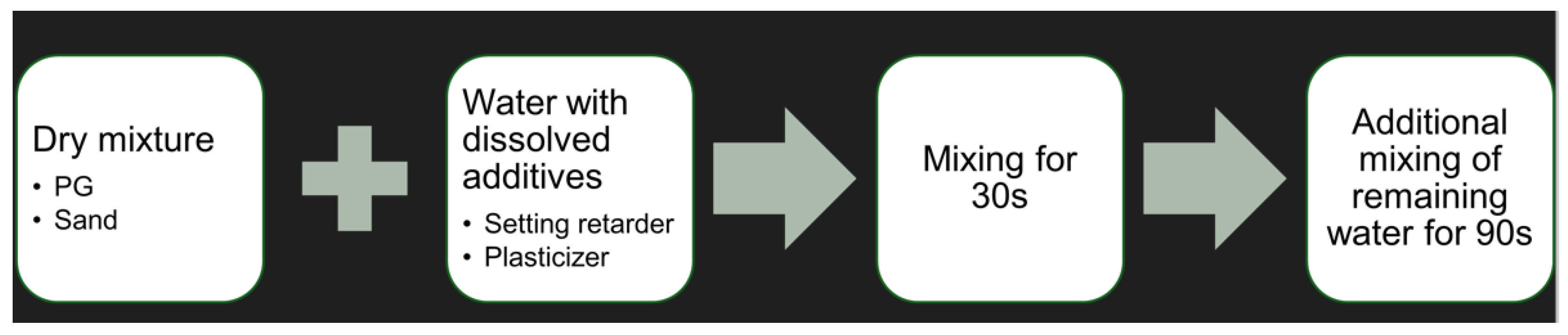
Preparation of the Mixture
2.2. Experimental Techniques
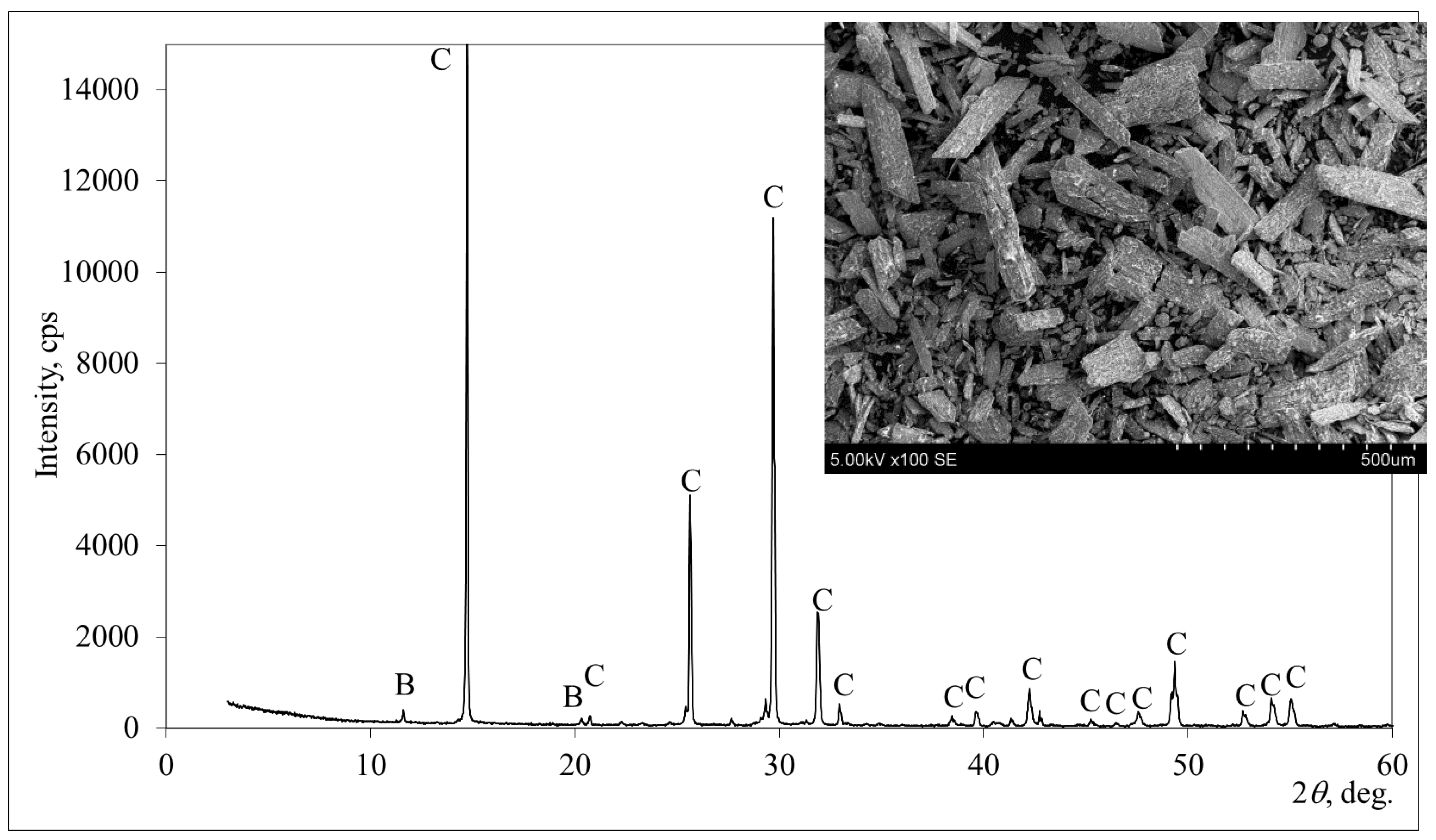
2.2.1. Chemical Composition and Microstructural Properties
- Microstructure: SEM. Device: Hitachi S-3400N type II SEM microscope with an incorporated Bruker Quad 5040 detector (Tokyo, Japan).
- Elemental composition: XRF. Device: Bruker X-ray S8 Tiger WD spectrometer (Karlsruhe, Germany).
- Acidic water-soluble phosphate and fluoride content: colorimetric method. Devices: Hanna HI713 Checker HC®—Phosphate LR colorimeter (136); Hanna HI729 Checker HC®—Fluoride LR colorimeter (137) (Smithfield, VA, USA). Lithuanian technical conditions TS-21-154-86 was the reference according to which these analyses were performed [36].
- Mineral composition: XRD. Device: D8 Advance diffractometer, Bruker AXS (Karlsruhe Germany) (with geometry of Bragg–Brentano). Database for peak identification: PDF-2.
- Fineness of binding material: air permeability test (according to European standard EN 196-6) [37]. Device: Blaine air permeability apparatus.
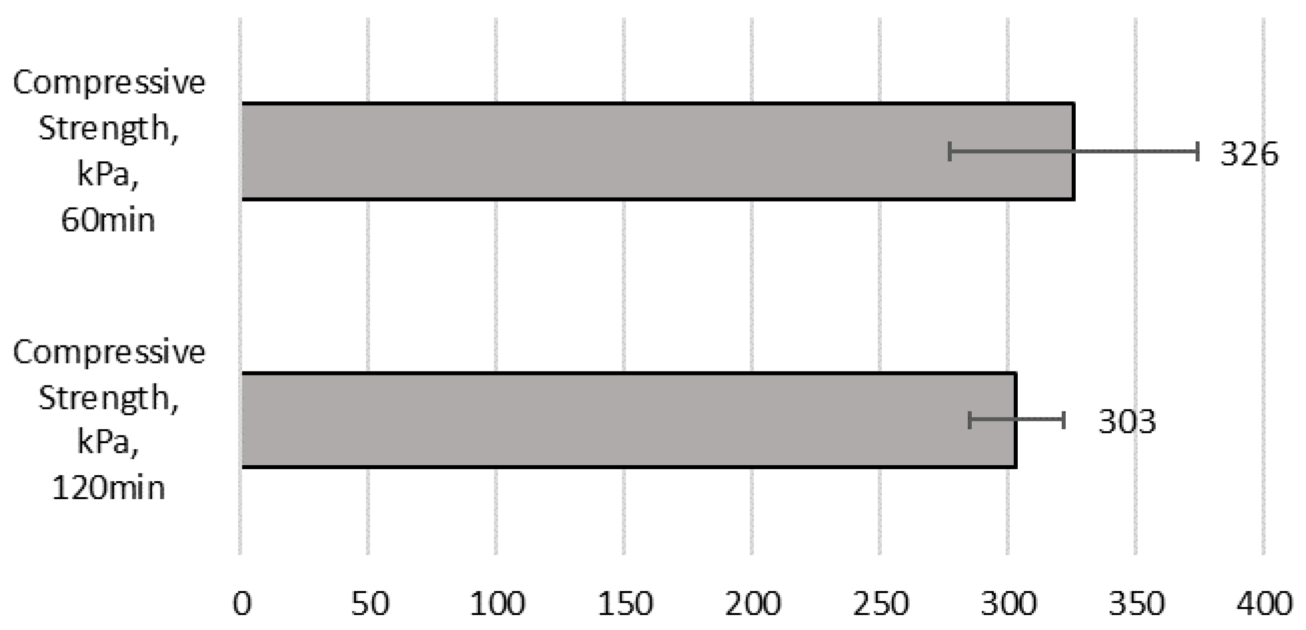
2.2.2. Rheological Properties and Setting Time
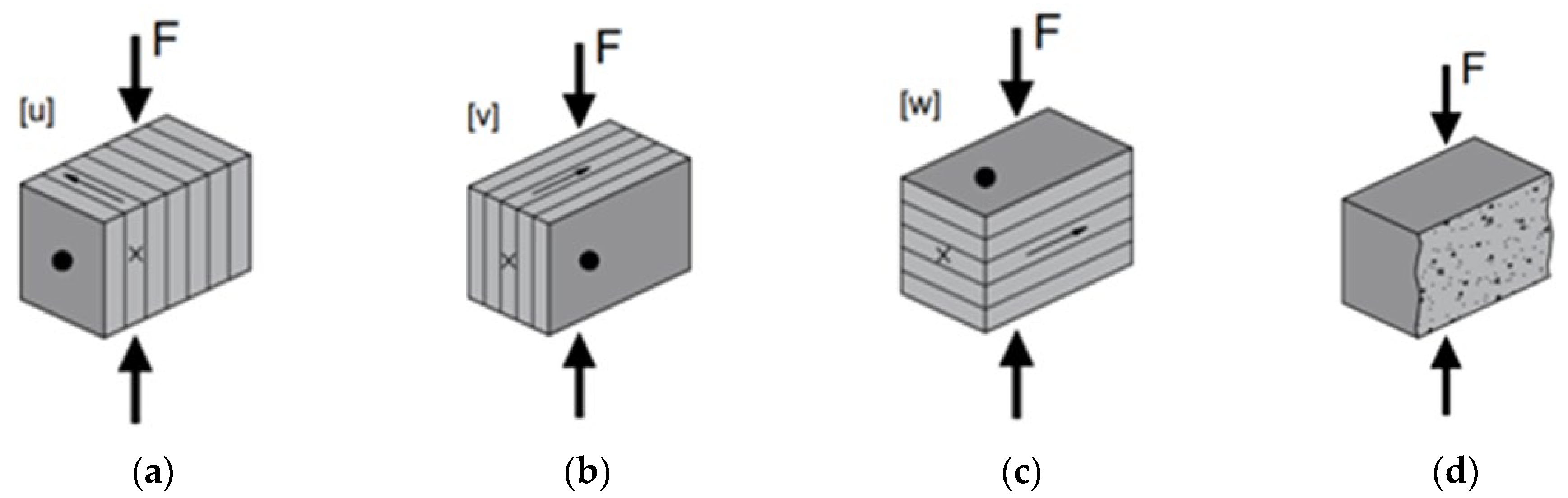
2.2.3. Testing Methods for the Mechanical Properties
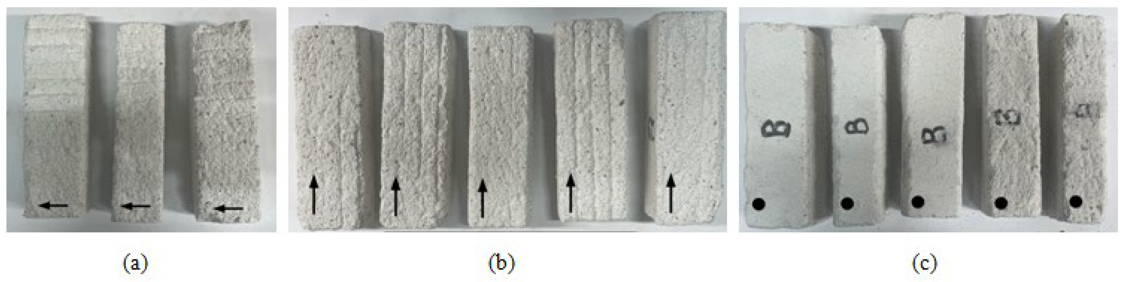
Preparation of Hardened Specimens
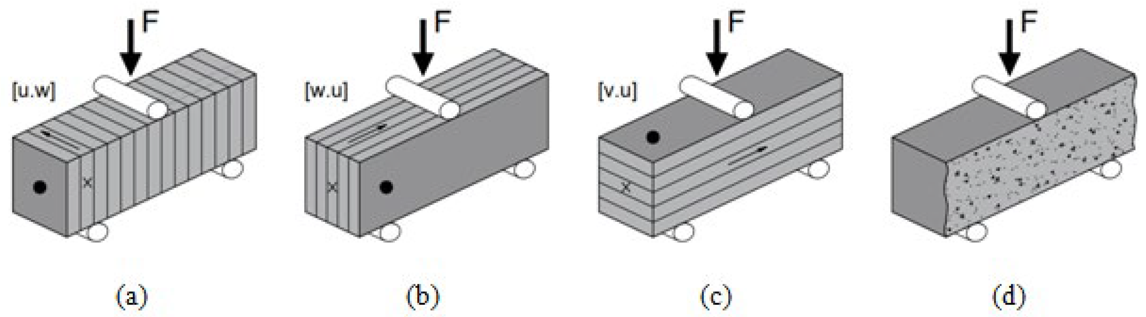
Test Procedure
3. Results and Discussion
3.1. Properties of the PG Mixture: Printability and Buildability
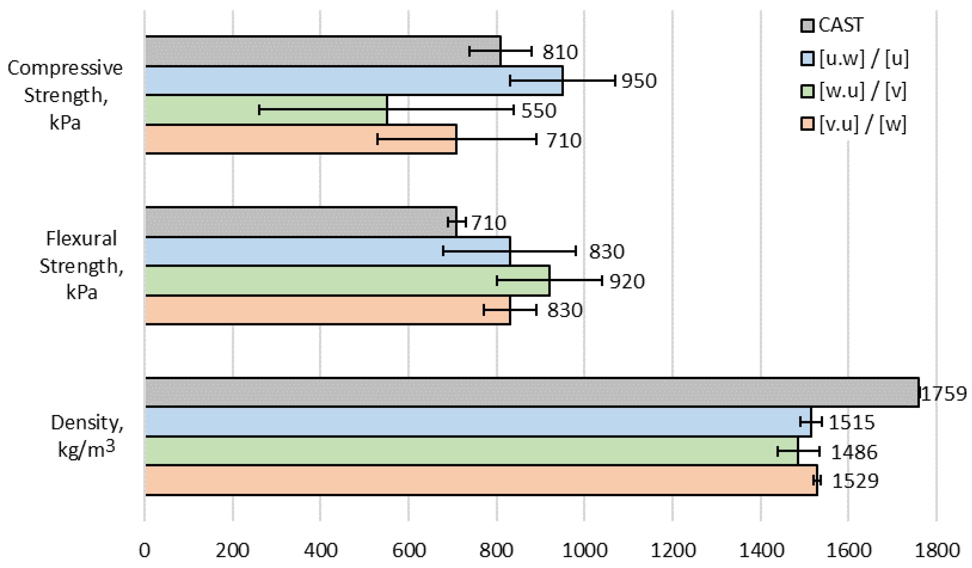
3.2. Mechanical Properties
4. Conclusions
- (1)
- In order to reduce the standard deviation of the compressive strength results in the future, specimens with a flat surface need to be prepared. Despite the challenging effects caused by the brittle material, the surface should be grinded after cutting, or even gypsum capping should be used to prepare the specimens.
- (2)
- The obtained PG mortar showed low mechanical strength results. Therefore, it is suitable in construction only when combined with load-bearing structures or in cases when a structure that needs to hold only its own self-weight is produced. Such structures include permanent moulds and acoustic wall panels.
- (3)
- The manufacturing of such elements is well suited for 3D-printing technology. It allows for the production of complex geometry without significant deviations, and this can be achieved an unlimited number of times. Additionally, the obtained results show that despite the low compaction degree, 3D printing increases the mechanical properties for this material in comparison to the cast specimens.
- (4)
- The compaction degree of the printed element was low due to the low self-weight of the mixture. This might also affect not just mechanical strength but also durability, which was not investigated in this research. A higher degree of compaction could potentially be achieved by slightly increasing the W/PG ratio or by raising the extrusion rate.
Author Contributions
Funding
Institutional Review Board Statement
Informed Consent Statement
Data Availability Statement
Conflicts of Interest
Abbreviations
References
- U.S. Geological Survey. Mineral Commodity Summaries 2024; USGS Publications Warehouse: Reston, VA, USA, 2024; ISBN 978-1-4113-4544-7. [Google Scholar]
- IAEA. Radiation Protection and Management of NORM Residues in the Phosphate Industry, Safety Reports Series No. 78; International Atomic Energy Agency (IAEA): Vienna, Austria, 2013; ISBN 978-92-0135810-3. [Google Scholar]
- Rashad, A.M. Phosphogypsum as a Construction Material. J. Clean. Prod. 2017, 166, 732–743. [Google Scholar] [CrossRef]
- Qi, J.; Zhu, H.; Zhou, P.; Wang, X.; Wang, Z.; Yang, S.; Yang, D.; Li, B. Application of Phosphogypsum in Soilization: A Review. Int. J. Environ. Sci. Technol. 2023, 20, 10449–10464. [Google Scholar] [CrossRef]
- Folek, S.; Walawska, B.; Wilczek, B.; Miśkiewicz, J. Use of Phosphogypsum in Road Construction. Pol. J. Chem. Technol. 2011, 13, 18–22. [Google Scholar] [CrossRef]
- Sarkka, A. Life Environment in Action: 56 New Success Stories for Europe’s Environment; Office for Official Publications of the European Communities: Luxembourg, 2001; pp. 98–99, Disposal Management System for Utilisation of Industrial Phosphogypsum and Fly Ash; ISBN 92-894-0272-5. [Google Scholar]
- Saadaoui, E.; Ghazel, N.; Romdhane, C.B.; Massoudi, N. Phosphogypsum: Potential Uses and Problems—A Review. Int. J. Environ. Stud. 2017, 74, 558–567. [Google Scholar] [CrossRef]
- Dvorkin, L.; Lushnikova, N.; Sonebi, M. Application Areas of Phosphogypsum in Production of Mineral Binders and Composites Based on them: A Review of Research Results. MATEC Web Conf. 2018, 149, 01012. [Google Scholar] [CrossRef]
- Bhanumathidas, N.; Kalidas, N. Dual Role of Gypsum: Set Retarder and Strength Accelerator. Indian Concr. J. 2004, 78, 170–173. [Google Scholar]
- Islam, G.S.; Chowdhury, F.H.; Raihan, M.T.; Amit, S.K.S.; Islam, M.R. Effect of Phosphogypsum on the Properties of Portland Cement. Procedia Eng. 2017, 171, 744–751. [Google Scholar] [CrossRef]
- Akın, A.İ.; Sert, Y. Utilization of Weathered Phosphogypsum as Set Retarder in Portland Cement. Cem. Concr. Res. 2004, 34, 677–680. [Google Scholar] [CrossRef]
- Zhou, J.; Yu, D.; Shu, Z.; Li, T.; Chen, Y.; Wang, Y. A Novel Two-Step Hydration Process of Preparing Cement-Free Non-Fired Bricks from Waste Phosphogypsum. Constr. Build. Mater. 2014, 73, 222–228. [Google Scholar] [CrossRef]
- Fornés, I.V.; Doroševas, V.; Vaičiukynienė, D.; Nizevičienė, D. The Investigation of Phosphogypsum Specimens Processed by Press-Forming Method. Waste Biomass Valorization 2021, 12, 1539–1551. [Google Scholar] [CrossRef]
- Zhou, J.; Sheng, Z.; Li, T.; Shu, Z.; Chen, Y.; Wang, Y. Preparation of Hardened Tiles from Waste Phosphogypsum by a New Intermittent Pressing Hydration. Ceram. Int. 2016, 42, 7237–7245. [Google Scholar] [CrossRef]
- Zhou, J.; Li, X.; Zhao, Y.; Shu, Z.; Wang, Y.; Zhang, Y.; Shen, X. Preparation of Paper-Free and Fiber-Free Plasterboard with High Strength using Phosphogypsum. Constr. Build. Mater. 2020, 243, 118091. [Google Scholar] [CrossRef]
- Gibson, I.; Rosen, D.W.; Stucker, B.; Khorasani, M. Additive Manufacturing Technologies, 3rd ed.; Springer: Cham, Switzerland, 2021; ISBN 978-3-030-56126-0. [Google Scholar]
- Camacho, D.D.; Clayton, P.; O’Brien, W.J.; Seepersad, C.; Juenger, M.; Ferron, R.; Salamone, S. Applications of Additive Manufacturing in the Construction Industry—A Forward-Looking Review. Autom. Constr. 2018, 89, 110–119. [Google Scholar] [CrossRef]
- Pegna, J. Exploratory Investigation of Solid Freeform Construction. Autom. Constr. 1997, 5, 427–437. [Google Scholar] [CrossRef]
- Hou, S.; Duan, Z.; Xiao, J.; Ye, J. A Review of 3D Printed Concrete: Performance Requirements, Testing Measurements and Mix Design. Constr. Build. Mater. 2021, 273, 121745. [Google Scholar] [CrossRef]
- El-Sayegh, S.; Romdhane, L.; Manjikian, S. A Critical Review of 3D Printing in Construction: Benefits, Challenges, and Risks. Arch. Civ. Mech. Eng. 2020, 20, 34. [Google Scholar] [CrossRef]
- Perrot, A.; Rangeard, D.; Courteille, E. 3D Printing of Earth-Based Materials: Processing Aspects. Constr. Build. Mater. 2018, 172, 670–676. [Google Scholar] [CrossRef]
- Zhang, Z.; Provis, J.L.; Reid, A.; Wang, H. Geopolymer Foam Concrete: An Emerging Material for Sustainable Construction. Constr. Build. Mater. 2014, 56, 113–127. [Google Scholar] [CrossRef]
- Wu, P.; Wang, J.; Wang, X. A Critical Review of the use of 3-D Printing in the Construction Industry. Autom. Constr. 2016, 68, 21–31. [Google Scholar] [CrossRef]
- Ali, M.H.; Issayev, G.; Shehab, E.; Sarfraz, S. A Critical Review of 3D Printing and Digital Manufacturing in Construction Engineering. Rapid Prototyp. J. 2022, 28, 1312–1324. [Google Scholar] [CrossRef]
- Peng, Y.; Unluer, C. Development of Alternative Cementitious Binders for 3D Printing Applications: A Critical Review of Progress, Advantages and Challenges. Compos. Part B Eng. 2023, 252, 110492. [Google Scholar] [CrossRef]
- Aslan, R.; Turan, O. Gypsum-Based Sound Absorber Produced by 3D Printing Technology. Appl. Acoust. 2020, 161, 107162. [Google Scholar] [CrossRef]
- Huang, J.; Duan, B.; Cai, P.; Manuka, M.; Hu, H.; Hong, Z.; Cao, R.; Jian, S.; Ma, B. On-Demand Setting of Extrusion-Based 3D Printing Gypsum using a Heat-Induced Accelerator. Constr. Build. Mater. 2021, 304, 124624. [Google Scholar] [CrossRef]
- Kong, L.; Ostadhassan, M.; Li, C.; Tamimi, N. Can 3-D Printed Gypsum Samples Replicate Natural Rocks? an Experimental Study. Rock Mech. Rock Eng. 2018, 51, 3061–3074. [Google Scholar] [CrossRef]
- Ma, B.; Jiang, Q.; Huang, J.; Wang, X.; Leng, J. Effect of Different Silica Particles on Flowability of Gypsum Powder for 3D Powder Printing. Constr. Build. Mater. 2019, 217, 394–402. [Google Scholar] [CrossRef]
- Gong, L.; Zhou, Y.; Zheng, L.; Yuan, P.F. Extrusion-Based 3D Printing for Recyclable Gypsum. POST-CARBON. In Proceedings of the 27th International Conference of the Association for Computer-Aided Architectural Design Research in Asia (CAADRIA), Sydney, Australia, 9–15 April 2022; Volume 2, pp. 273–282. Available online: https://papers.cumincad.org/data/works/att/caadria2022_476.pdf (accessed on 9 November 2024).
- Cao, W.; Yi, W.; Peng, J.; Li, J.; Yin, S. Recycling of Phosphogypsum to Prepare Gypsum Plaster: Effect of Calcination Temperature. J. Build. Eng. 2022, 45, 103511. [Google Scholar] [CrossRef]
- Guan, Q.; Wang, Z.; Zhou, F.; Yu, W.; Yin, Z.; Zhang, Z.; Chi, R.; Zhou, J. The Impurity Removal and Comprehensive Utilization of Phosphogypsum: A Review. Materials 2024, 17, 2067. [Google Scholar] [CrossRef]
- Jia, W.; Li, J.; Shen, C.; Li, G.; Li, H.; Fan, G.; Zhou, G.; Cao, Y. Research advances in phosphogypsum flotation purification: Current status and prospects. Sep. Purif. Technol. 2024, 359 Pt 6, 129244. [Google Scholar] [CrossRef]
- Awad, S.; Essam, M.; Boukhriss, A.; Kamar, M.; Midani, M. Properties, purification, and applications of phosphogypsum: A comprehensive review towards circular economy. Mater. Circ. Econ. 2024, 6, 9. [Google Scholar] [CrossRef]
- Fornés, I.V.; Vaičiukynienė, D.; Nizevičienė, D.; Doroševas, V.; Michalik, B. A Comparative Assessment of the Suitability of Phosphogypsum from Different Origins to be Utilised as the Binding Material of Construction Products. J. Build. Eng. 2021, 44, 102995. [Google Scholar] [CrossRef]
- TS-21-154-86; Lithuanian Technical Conditions. Determination of Water-Soluble Phosphate and Fluoride Content, Colorimetric Method.
- EN 196-6; Methods of Testing Cement—Part 6: Determination of Fineness. European Committee for Standartization: Brussels, Belgium, 2010.
- Kruger, J.; Zeranka, S.; van Zijl, G. 3D Concrete Printing: A Lower Bound Analytical Model for Buildability Performance Quantification. Autom. Constr. 2019, 106, 102904. [Google Scholar] [CrossRef]
- EN 1015-3; Methods of Test for Mortar for Masonry—Part 3: Determination of Consistence of Fresh Mortar (by Flow Table). CEN/TC 125 Masonry. European Committee for Standartization: Brussels, Belgium, 1999.
- EN 196-3; Methods of Testing Cement—Part 3: Determination of Setting Times and Soundness. Brussels: CEN/TC 51 Cement and Building Limes. European Committee for Standartization: Brussels, Belgium, 2016.
- EN 1015-11; Methods of Test for Mortar for Masonry—Part 11: Determination of Flexural and Compressive Strength of Hardened Mortar. CEN/TC 125 Masonry. European Committee for Standartization: Brussels, Belgium, 1999.
- Mechtcherine, V.; van Tittelboom, K.; Kazemian, A.; Kreiger, E.; Nematollahi, B.; Nerella, V.N.; Santhanam, M.; de Schutter, G.; Van Zijl, G.; Lowke, D.; et al. A Roadmap for Quality Control of Hardening and Hardened Printed Concrete. Cem. Concr. Res. 2022, 157, 106800. [Google Scholar] [CrossRef]
- Bumanis, G.; Sapata, A.; Sinka, M.; Spurina, E.; Bajare, D. Additive Manufacturing of Lightweight Gypsum and Expanded Polystyrene Granulate Composite. J. Compos. Sci. 2023, 7, 425. [Google Scholar] [CrossRef]
- Joh, C.; Lee, J.; Bui, T.Q.; Park, J.; Yang, I.H. Buildability and mechanical properties of 3D printed concrete. Materials 2020, 13, 4919. [Google Scholar] [CrossRef]
- Lee, H.; Kim, J.-H.J.; Moon, J.-H.; Kim, W.-W.; Seo, E.-A. Evaluation of the mechanical properties of a 3D-printed mortar. Materials 2019, 12, 4104. [Google Scholar] [CrossRef]
- Yang, H.; Li, W.; Che, Y. 3D printing cementitious materials containing nano-CaCO3: Workability, strength, and microstructure. Front. Mater. 2020, 7, 260. [Google Scholar] [CrossRef]
- Zahabizadeh, B.; Pereira, J.; Gonçalves, C.; Pereira, E.N.; Cunha, V.M. Influence of the printing direction and age on the mechanical properties of 3D printed concrete. Mater. Struct. 2021, 54, 73. [Google Scholar] [CrossRef]


| CaO | SO3 | SiO2 | Al2O3 | MgO | F | Fe2O3 | P2O5 * | P2O5 ** | Other |
| 38.45 | 53.33 | 0.37 | 0.13 | 0.04 | 0.14 | 0.03 | 0.82 | 0.40 | 6.70 |
| Sample No. | Retarder wt. % * | Setting Times, min | W/PG Ratio | |
|---|---|---|---|---|
| Initial | Final | |||
| PG-1 | 0.1 | 24 | 42 | 0.7 |
| PG-2 | 0.2 | 40 | 75 | 0.7 |
| PG-3 | 0.4 | 47 | 86 | 0.7 |
| PG-4 | 1.0 | Did not set after 2 h. | Did not set after 2 h. | 0.7 |
| PG-5 | 2.0 | Did not set after 2 h. | Did not set after 2 h. | 0.7 |
| Sample No. | Binding Material (PG + CaO) | Sand | Plasticiser * | Set Retarder * | W/PG |
|---|---|---|---|---|---|
| PG-1.1 | 40 | 60 | 1.2 | 0.4 | 0.68 |
| PG-1.1C | 40 | 60 | 1.2 | 0.4 | 0.68 |
| Property | Time, min | Spread Diameter, mm | Obtained Shape |
|---|---|---|---|
| After 15 jolts | 5 | 205 | 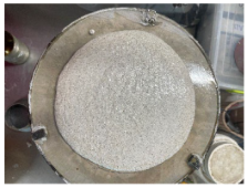 |
| After 15 jolts | 10 | 200 | 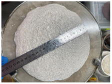 |
| After 15 jolts | 25 | 192 |  |
Disclaimer/Publisher’s Note: The statements, opinions and data contained in all publications are solely those of the individual author(s) and contributor(s) and not of MDPI and/or the editor(s). MDPI and/or the editor(s) disclaim responsibility for any injury to people or property resulting from any ideas, methods, instructions or products referred to in the content. |
© 2024 by the authors. Licensee MDPI, Basel, Switzerland. This article is an open access article distributed under the terms and conditions of the Creative Commons Attribution (CC BY) license (https://creativecommons.org/licenses/by/4.0/).
Share and Cite
Sinka, M.; Vaičiukynienė, D.; Nizevičienė, D.; Sapata, A.; Fornés, I.V.; Vaitkevičius, V.; Šerelis, E. Utilisation of By-Product Phosphogypsum Through Extrusion-Based 3D Printing. Materials 2024, 17, 5570. https://doi.org/10.3390/ma17225570
Sinka M, Vaičiukynienė D, Nizevičienė D, Sapata A, Fornés IV, Vaitkevičius V, Šerelis E. Utilisation of By-Product Phosphogypsum Through Extrusion-Based 3D Printing. Materials. 2024; 17(22):5570. https://doi.org/10.3390/ma17225570
Chicago/Turabian StyleSinka, Maris, Danutė Vaičiukynienė, Dalia Nizevičienė, Alise Sapata, Ignacio Villalón Fornés, Vitoldas Vaitkevičius, and Evaldas Šerelis. 2024. "Utilisation of By-Product Phosphogypsum Through Extrusion-Based 3D Printing" Materials 17, no. 22: 5570. https://doi.org/10.3390/ma17225570
APA StyleSinka, M., Vaičiukynienė, D., Nizevičienė, D., Sapata, A., Fornés, I. V., Vaitkevičius, V., & Šerelis, E. (2024). Utilisation of By-Product Phosphogypsum Through Extrusion-Based 3D Printing. Materials, 17(22), 5570. https://doi.org/10.3390/ma17225570