
Recent Advances in Additive Friction Stir Deposition: A Critical Review

Abstract
1. Introduction
1.1. Metal Welding by Solid-State Principle
1.2. Additive Manufacturing Technology Driven by Friction Stir Principle
1.3. Comparison between Additive Friction Stir Deposition and Fusion-Based Additive Manufacturing
2. Methods
2.1. Strategy of Search and Selection
2.2. Criteria of Inclusion and Exclusion
3. Process
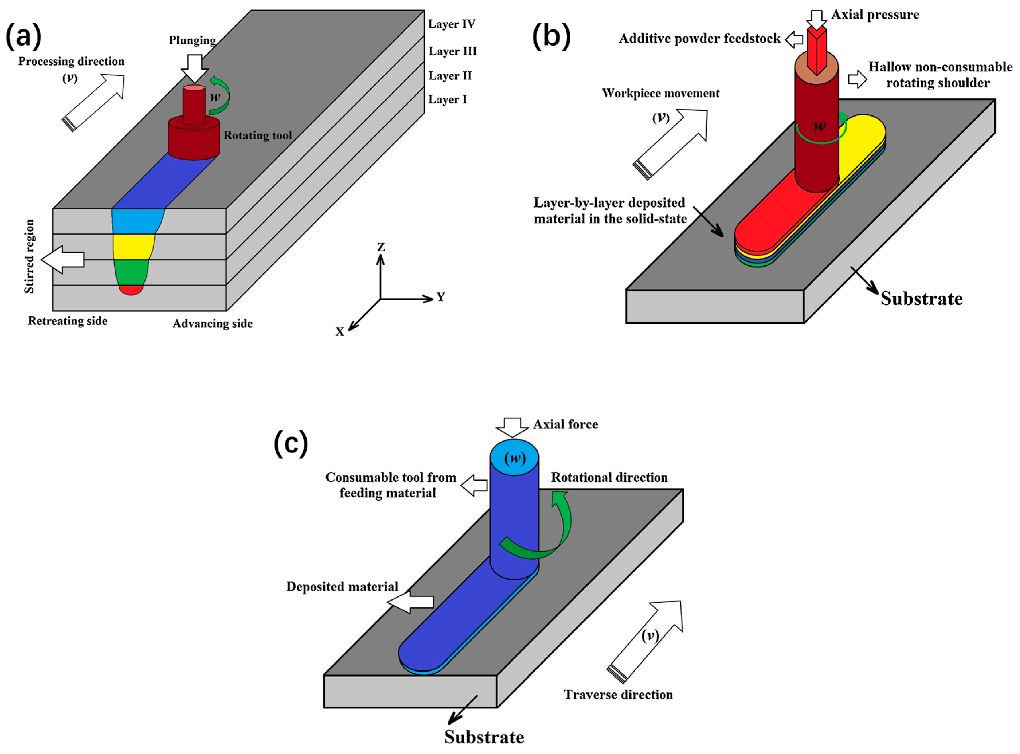
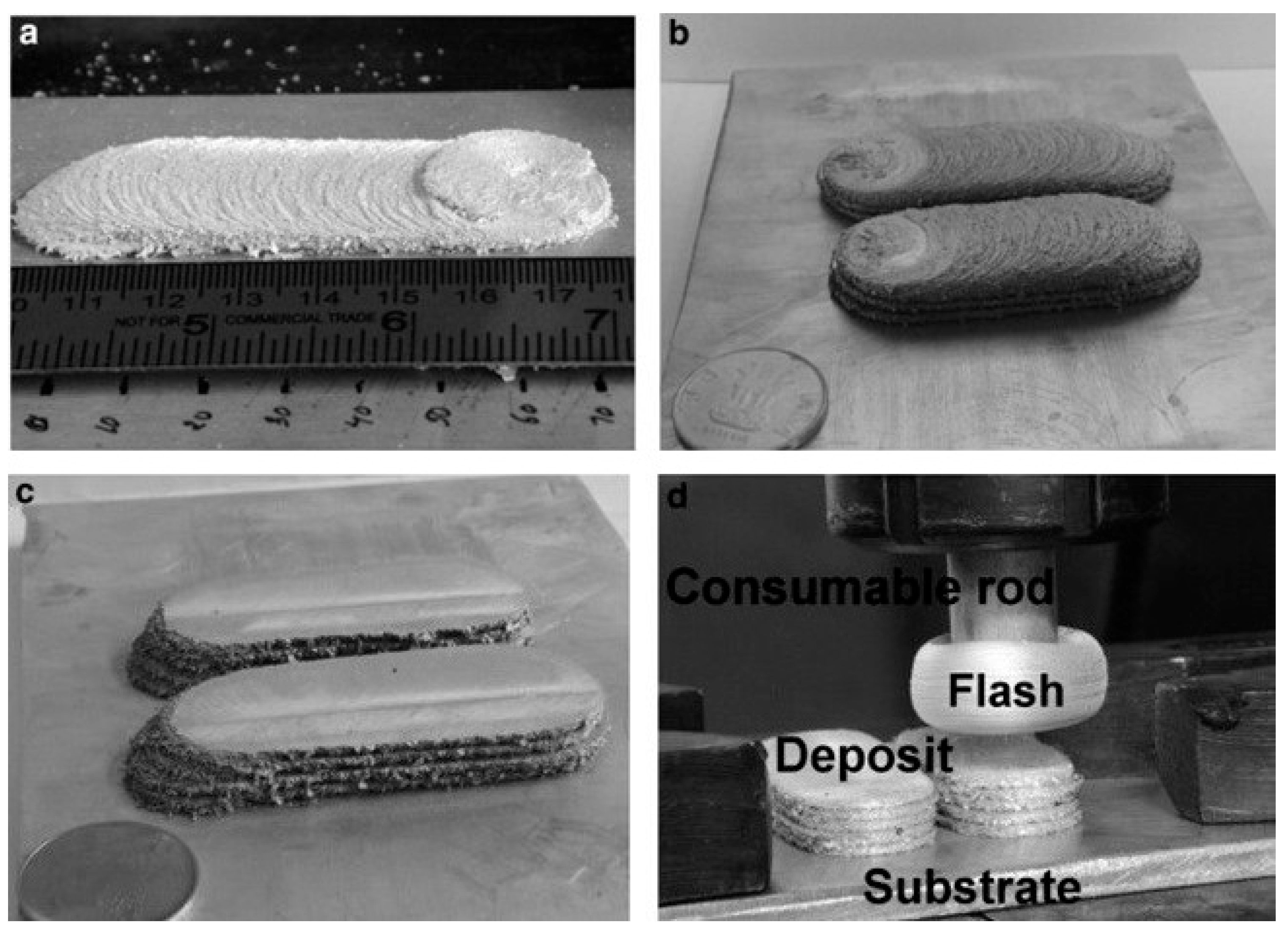
3.1. Additive Friction Stir Deposition Using Consumable Print Head
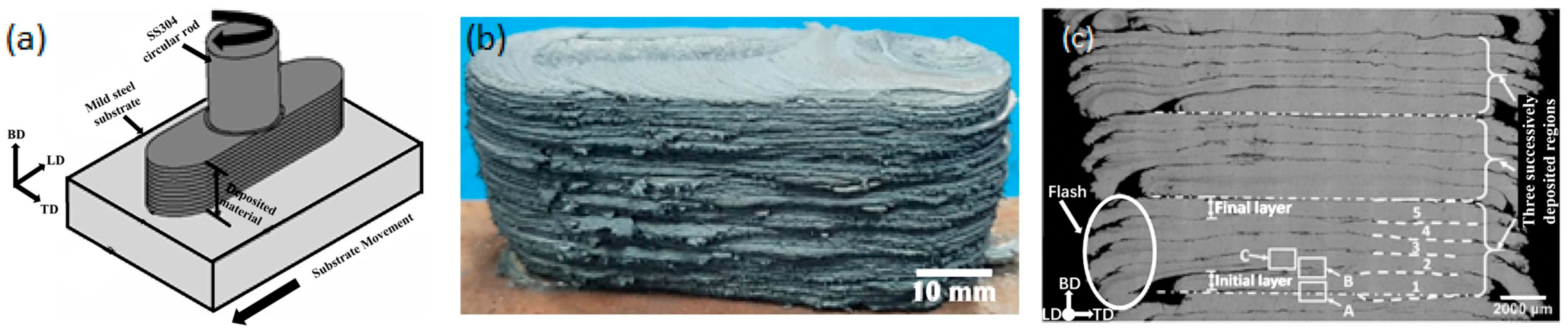
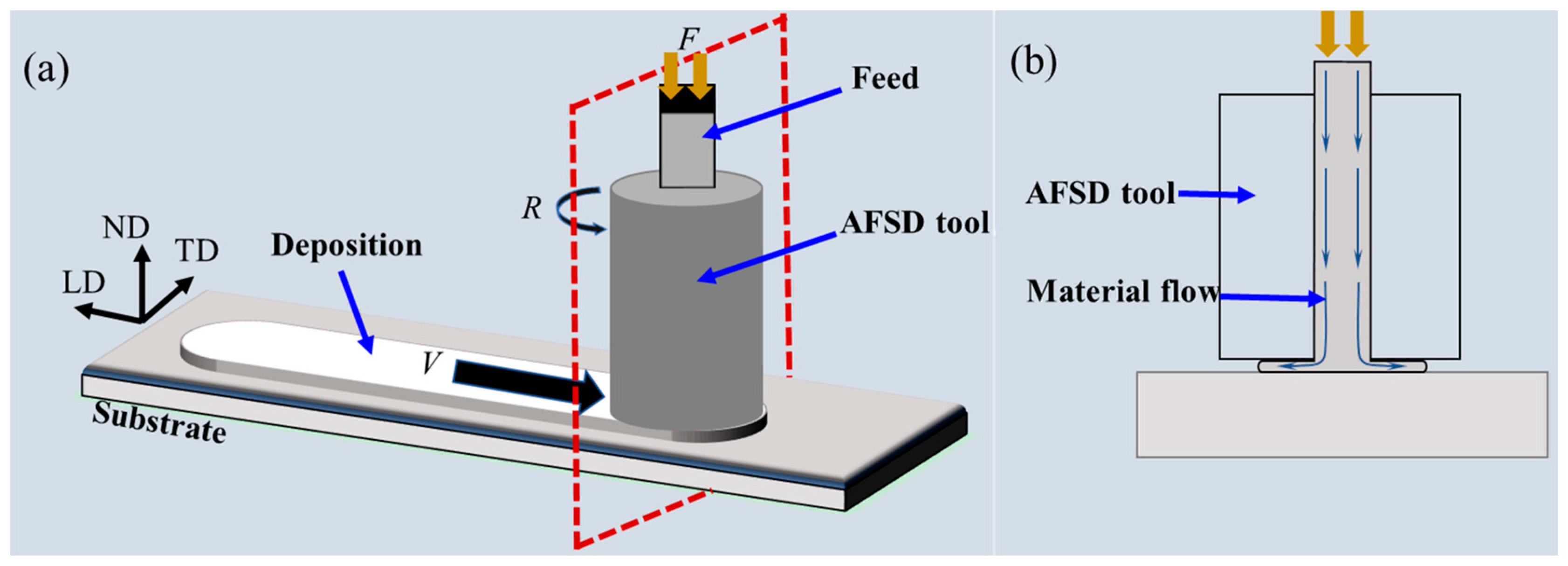
3.2. Additive Friction Stir Deposition by Non-Consumable Print Head
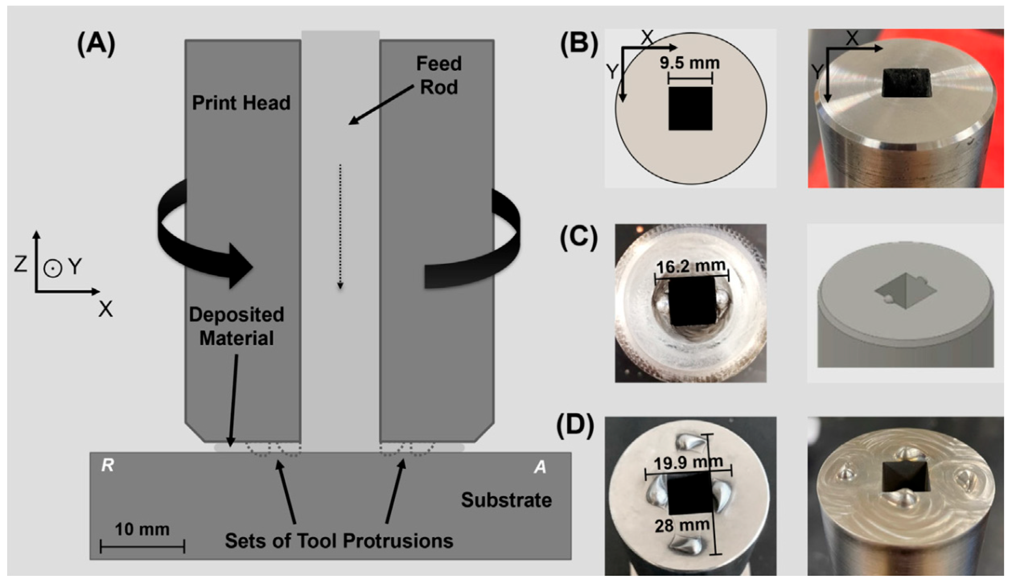
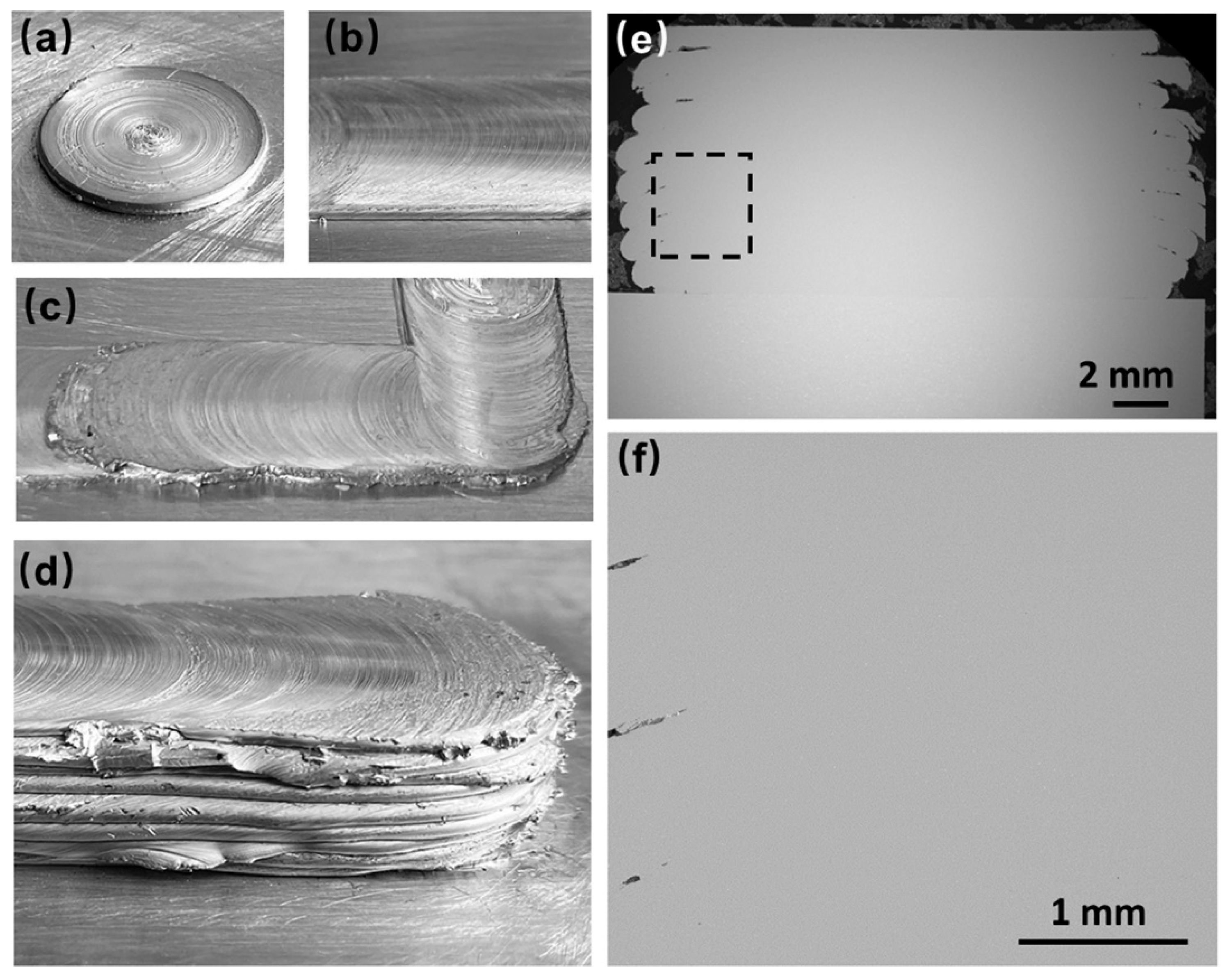
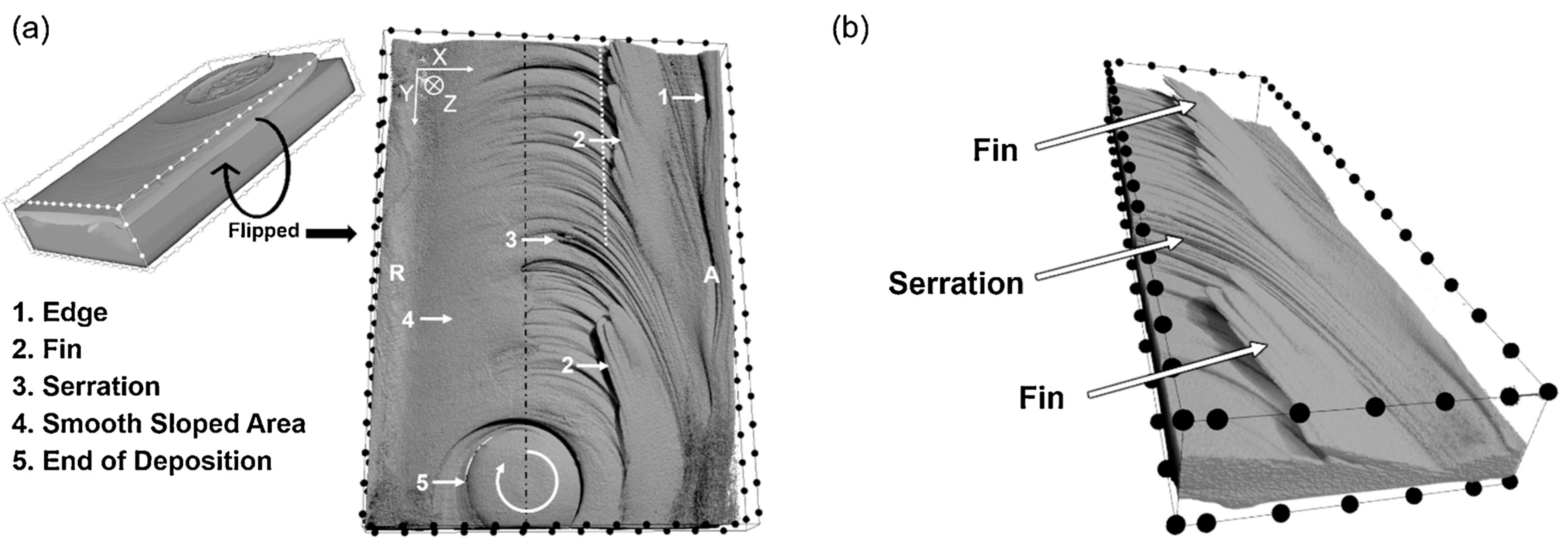
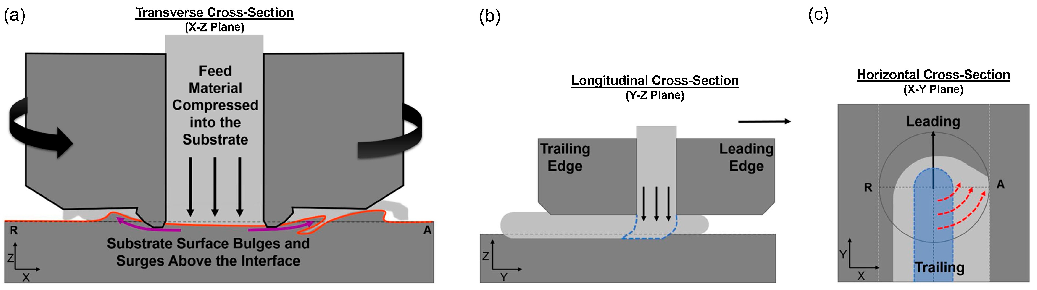
3.2.1. Rod as Feedstock
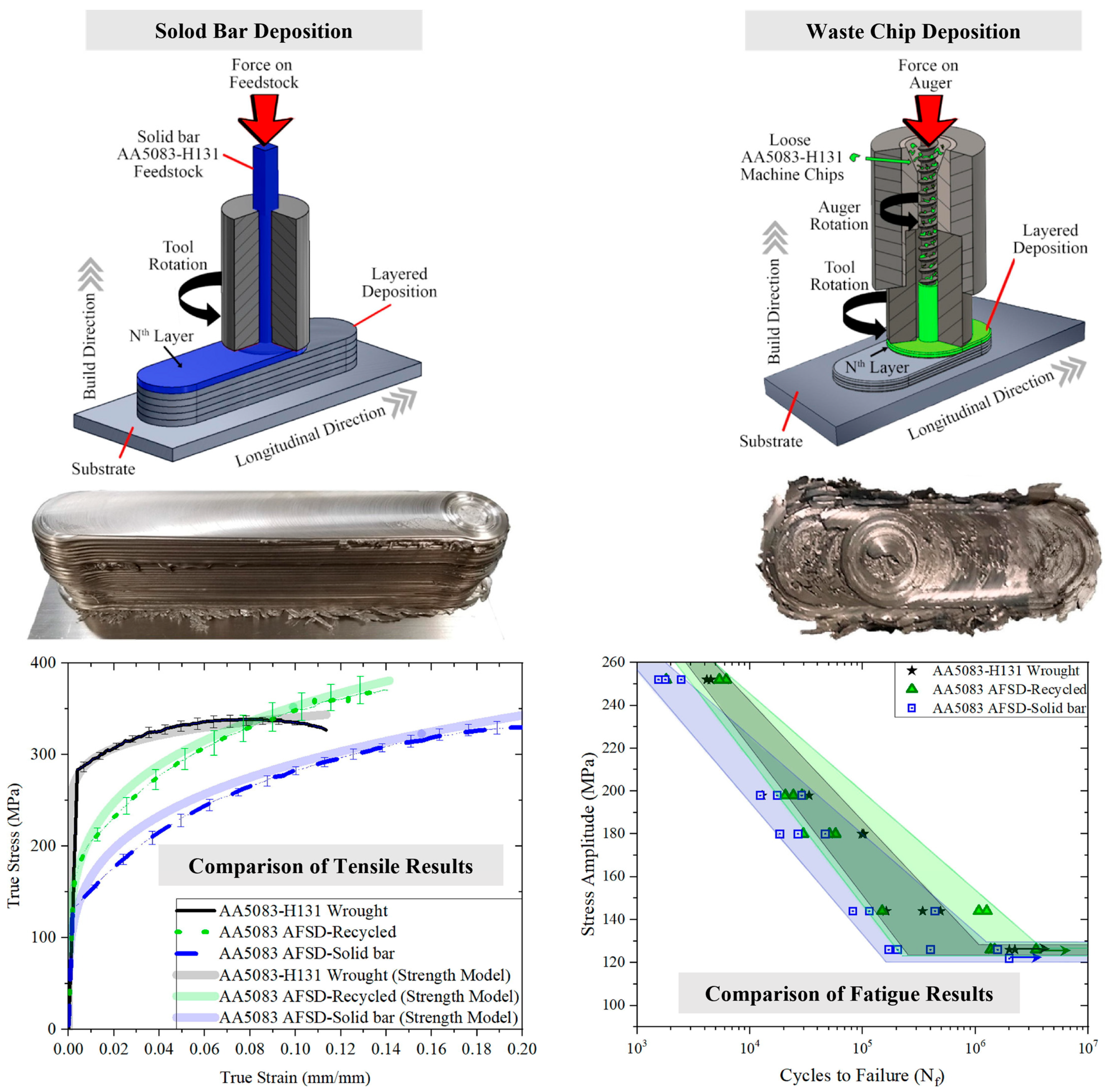
3.2.2. Powder/Chip as Feedstock
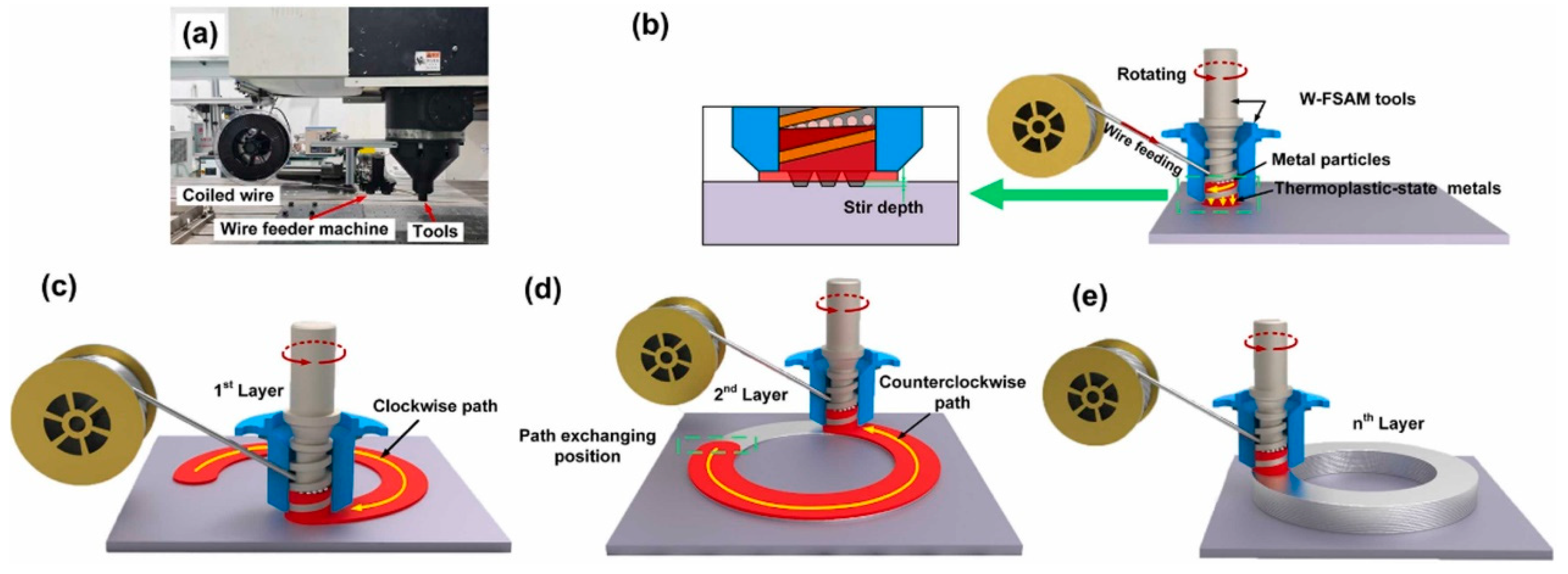
3.2.3. Wire as Feedstock
4. Microstructure Evolution and Mechanical Properties
4.1. Related Research on Aluminum Alloys
4.2. Related Research on Magnesium Alloys
4.3. Related Research on Other Alloys
5. Opportunities and Challenges
5.1. Improvement of Molding Quality and Spatial Resolution
5.2. Control and Improvement of Microstructure and Performance
5.3. Optimization of Process Parameters
6. Conclusions
Funding
Data Availability Statement
Conflicts of Interest
References
- Tobin, D.; O’Shaughnessy, S.; Trimble, D. Characterisation of force and torque with auxiliary heating during friction stir spot welding of AA2024-T3. Results Mater. 2024, 21, 100535. [Google Scholar] [CrossRef]
- Kumar Srivastava, A.; Kumar, N.; Rai Dixit, A. Friction stir additive manufacturing—An innovative tool to enhance mechanical and microstructural properties. Mater. Sci. Eng. B 2021, 263, 114832. [Google Scholar] [CrossRef]
- Geng, Y.; Zhou, M.; Zhu, Y.; Chen, Y.; Xin, T.; Chen, G.; Wu, R.; Shi, Q. Regulating microstructure of Mg–Li–Al–Zn alloy for enhancing comprehensive performance through friction stir additive manufacturing. Mater. Sci. Eng. A 2024, 895, 146239. [Google Scholar] [CrossRef]
- Khodabakhshi, F.; Gerlich, A.P. Potentials and strategies of solid-state additive friction-stir manufacturing technology: A critical review. J. Manuf. Process. 2018, 36, 77–92. [Google Scholar] [CrossRef]
- Shao, J.; Samaei, A.; Xue, T.; Xie, X.; Guo, S.; Cao, J.; MacDonald, E.; Gan, Z. Additive friction stir deposition of metallic materials: Process, structure and properties. Mater. Des. 2023, 234, 112356. [Google Scholar] [CrossRef]
- Rappaz, M.; Gandin, C.A. Probabilistic modelling of microstructure formation in solidification processes. Acta Metall. Mater. 1993, 41, 345–360. [Google Scholar] [CrossRef]
- Li, H.Z.; Wang, C.M.; Zhang, H.; Zhang, J.J.; He, P.; Shao, M.H.; Zhu, X.T.; Fu, Y.Q. Research Progress of Friction Stir Additive Manufacturing Technology. Acta Metall. Sin. 2023, 59, 106–124. [Google Scholar] [CrossRef]
- Seidi, E.; Miller, S.F. A Novel Approach to Friction Surfacing: Experimental Analysis of Deposition from Radial Surface of a Consumable Tool. Coatings 2020, 10, 1016. [Google Scholar] [CrossRef]
- Dilip, J.J.S.; Janaki Ram, G.D. Microstructure evolution in aluminum alloy AA 2014 during multi-layer friction deposition. Mater. Charact. 2013, 86, 146–151. [Google Scholar] [CrossRef]
- Messler, R.W. Principles of Welding; Wiley & Sons: Hoboken, NJ, USA, 2008. [Google Scholar]
- Gotawala, N.; Kumar Mishra, N.; Shrivastava, A. Solid-state depositions of multilayer SS304 by friction stir metal deposition. Mater. Lett. 2022, 314, 131881. [Google Scholar] [CrossRef]
- Gong, W.; Li, Y.; Zhang, M.; Wang, H.; Liu, Q.; Zeng, Z.; Ma, K.; Yang, B.; Lai, R.; Li, Y. Influence of Preheating Temperature on the Microstructure and Mechanical Properties of 6061/TA1 Composite Plates Fabricated by AFSD. Materials 2023, 16, 6018. [Google Scholar] [CrossRef] [PubMed]
- Yu, H.Z. Chapter 5—Effects of tool geometry. In Additive Friction Stir Deposition; Yu, H.Z., Ed.; Elsevier: Amsterdam, The Netherlands, 2022; pp. 183–201. [Google Scholar]
- Liu, F.; Dong, P.; Khan, A.S.; Zhang, Y.; Cheng, R.; Taub, A.; Ma, Z. 3D printing of fine-grained aluminum alloys through extrusion-based additive manufacturing: Microstructure and property characterization. J. Mater. Sci. Technol. 2023, 139, 126–136. [Google Scholar] [CrossRef]
- Perry, M.E.J.; Griffiths, R.J.; Garcia, D.; Sietins, J.M.; Zhu, Y.; Yu, H.Z. Morphological and microstructural investigation of the non-planar interface formed in solid-state metal additive manufacturing by additive friction stir deposition. Addit. Manuf. 2020, 35, 101293. [Google Scholar] [CrossRef]
- Perry, M.E.J.; Rauch, H.A.; Griffiths, R.J.; Garcia, D.; Sietins, J.M.; Zhu, Y.; Zhu, Y.; Yu, H.Z. Tracing plastic deformation path and concurrent grain refinement during additive friction stir deposition. Materialia 2021, 18, 101159. [Google Scholar] [CrossRef]
- Tang, W.; Yang, X.; Tian, C.; Xu, Y. Microstructural heterogeneity and bonding strength of planar interface formed in additive manufacturing of Al−Mg−Si alloy based on friction and extrusion. Int. J. Miner. Metall. Mater. 2022, 29, 1755–1769. [Google Scholar] [CrossRef]
- Calvert, J.R. Microstructure and Mechanical Properties of WE43 Alloy Produced Via Additive Friction Stir Technology. Master’s Thesis, Virginia Tech, Blacksburg, VA, USA, 2015. [Google Scholar]
- Mukhopadhyay, A.; Saha, P. Mechanical and microstructural characterization of aluminium powder deposit made by friction stir based additive manufacturing. J. Mater. Process. Technol. 2020, 281, 116648. [Google Scholar] [CrossRef]
- Mukhopadhyay, A.; Saha, P. Mechanical Characterization of Aluminium Alloy 6061 Powder Deposit Made by Friction Stir Based Additive Manufacturing. Key Eng. Mater. 2020, 846, 110–116. [Google Scholar] [CrossRef]
- Mukhopadhyay, A.; Saha, P. Microstructural Characterization of Aluminium Alloy 6061 Powder Deposit Made by Friction Stir Based Additive Manufacturing. In Advances in Production and Industrial Engineering; Springer: Singapore, 2021; pp. 137–146. [Google Scholar] [CrossRef]
- Mukhopadhyay, A.; Saha, P.; Singh, P.K.; Verma, M. Development and analysis of a powder bed friction stir (PBFS) additive manufacturing process for aluminum alloys: A study on friction-stirring pitch (ω/v) and print location. Addit. Manuf. 2023, 72, 103618. [Google Scholar] [CrossRef]
- Singh, P.K.; Mukhopadhyay, A.; Verma, M.; Saha, P. Feasibility study of AZ31B deposition made by novel powder bed friction stir process with optimal process parameters and tool features selection. Mater. Today Proc. 2023, in press. [Google Scholar] [CrossRef]
- Liu, Y.; Chen, G.; Zhang, H.; Yang, C.; Zhang, S.; Liu, Q.; Zhou, M.; Shi, Q. In situ exfoliation of graphite for fabrication of graphene/aluminum composites by friction stir processing. Mater. Lett. 2021, 301, 130280. [Google Scholar] [CrossRef]
- Liu, Y.; Chen, G.; Shi, F.; Qu, T.; Wen, F.; Yue, N.; Sun, C.; Zhou, M.; Yang, C.; Zhang, S.; et al. Atomically Resolved Structure of the Directly Bonded Aluminum–Carbon Interface in Aluminum–Graphite Composites by Solid-State Friction Stir Processing: Im plications for a High-Performance Aluminum Conductor. ACS Appl. Nano Mater. 2023, 6, 6103–6111. [Google Scholar] [CrossRef]
- Liu, Y.; Chen, G.; Shi, F.; Zhou, M.; Zhang, S.; Zhang, G.; Shi, Q. Graphite-Reinforced 6201 Aluminum Alloy Fabricated by In-Situ Friction Stir Processing: Process, Microstructure, and Mechanical/Electrical Properties. In Friction Stir Welding and Processing XII; Springer: Cham, Switzerland, 2023; pp. 63–72. [Google Scholar] [CrossRef]
- Liu, Y.; Shi, Q.; Qu, T.; Zhou, M.; Wen, F.; Yue, N.; Shi, F.; Sun, C.; Zhang, G.; Chen, G. Fabrication of graphite-reinforced 6201Al matrix composite with simultaneous enhancement of mechanical and electrical properties by multi-pass friction stir processing. J. Alloys Compd. 2023, 967, 171835. [Google Scholar] [CrossRef]
- Beck, S.C.; Williamson, C.J.; Kinser, R.P.; Rutherford, B.A.; Williams, M.B.; Phillips, B.J.; Doherty, K.J.; Allison, P.G.; Jordon, J.B. Examination of microstructure and mechanical properties of direct additive recycling for Al-Mg-Mn alloy Machine chip waste. Mater. Des. 2023, 228, 111733. [Google Scholar] [CrossRef]
- Chen, H.; Meng, X.; Chen, J.; Xie, Y.; Wang, J.; Sun, S.; Zhao, Y.; Li, J.; Wan, L.; Huang, Y. Wire-based friction stir additive manufacturing. Addit. Manuf. 2023, 70, 103557. [Google Scholar] [CrossRef]
- Zhang, Z.; Wan, L.; Meng, X.; Xie, Y.; Tian, H.; Mao, D.; Dong, W.; Sun, X.; Ma, X.; Huang, Y. Robotic wire-based friction stir additive manufacturing. Addit. Manuf. 2024, 88, 104261. [Google Scholar] [CrossRef]
- Rivera, O.G.; Allison, P.G.; Jordon, J.B.; Rodriguez, O.L.; Brewer, L.N.; McClelland, Z.; Whittington, W.R.; Francis, D.; Su, J.; Martens, R.L.; et al. Microstructures and mechanical behavior of Inconel 625 fabricated by solid-state additive manufacturing. Mater. Sci. Eng. A 2017, 694, 1–9. [Google Scholar] [CrossRef]
- Li, Y.; Zhang, M.; Wang, H.; Lai, R.; Yang, B.; Li, Y. Microstructure and mechanical properties of Al–Li alloy manufactured by additive friction stir deposition. Mater. Sci. Eng. A 2023, 887, 145753. [Google Scholar] [CrossRef]
- Rivera, O.G.; Allison, P.G.; Brewer, L.N.; Rodriguez, O.L.; Jordon, J.B.; Liu, T.; Whittington, W.R.; Martens, R.L.; McClelland, Z.; Mason, C.J.T.; et al. Influence of texture and grain refinement on the mechanical behavior of AA2219 fabricated by high shear solid state material deposition. Mater. Sci. Eng. A 2018, 724, 547–558. [Google Scholar] [CrossRef]
- Phillips, B.J.; Williamson, C.J.; Kinser, R.P.; Jordon, J.B.; Doherty, K.J.; Allison, P.G. Microstructural and Mechanical Characterization of Additive Friction Stir-Deposition of Aluminum Alloy 5083 Effect of Lubrication on Material Anisotropy. Materials 2021, 14, 6732. [Google Scholar] [CrossRef]
- Tang, W.; Yang, X.; Wang, R.; Luo, T. Tailoring microstructure of additive friction stir-deposited Al–Mg alloy through post-processing deformation treatment for enhancing mechanical performance. Mater. Sci. Eng. A 2023, 885, 145632. [Google Scholar] [CrossRef]
- Chen, L.; Li, Y.; Lu, L.; Yang, Z.; Ren, X.; Zhang, X. The effect of heat treatment on the microstructure and mechanical properties of multilayer AA6061 alloy fabricated by additive friction stir deposition. Mater. Today Commun. 2024, 38, 108078. [Google Scholar] [CrossRef]
- Rutherford, B.A.; Avery, D.Z.; Phillips, B.J.; Rao, H.M.; Doherty, K.J.; Allison, P.G.; Brewer, L.N.; Jordon, J.B. Effect of Thermomechanical Processing on Fatigue Behavior in Solid-State Additive Manufacturing of Al-Mg-Si Alloy. Metals 2020, 10, 947. [Google Scholar] [CrossRef]
- Tang, W.; Yang, X.; Tian, C. Influence of rotation speed on interfacial bonding mechanism and mechanical performance of aluminum 6061 fabricated by multilayer friction-based additive manufacturing. Int. J. Adv. Manuf. Technol. 2023, 126, 4119–4133. [Google Scholar] [CrossRef]
- Tang, W.; Yang, X.; Luo, T.; Wang, R.; Gu, C. Precipitation behavior and strengthening-toughening mechanism of additive friction stir-deposited Al–Mg–Si–Cu alloy. Addit. Manuf. 2023, 76, 103785. [Google Scholar] [CrossRef]
- Qiao, Q.; Wang, L.; Tam, C.W.; Gong, X.; Dong, X.; Lin, Y.; Lam, W.I.; Qian, H.; Guo, D.; Zhang, D.; et al. In-situ monitoring of additive friction stir deposition of AA6061: Effect of rotation speed on the microstructure and mechanical properties. Mater. Sci. Eng. A 2024, 902, 146620. [Google Scholar] [CrossRef]
- Qiao, Q.; Zhou, M.; Gong, X.; Jiang, S.; Lin, Y.; Wang, H.; Lam, W.I.; Qian, H.; Guo, D.; Zhang, D.; et al. In-situ monitoring of additive friction stir deposition of AA6061: Effect of layer thickness on the microstructure and mechanical properties. Addit. Manuf. 2024, 84, 104141. [Google Scholar] [CrossRef]
- Imam, M.; Racherla, V.; Biswas, K.; Fujii, H.; Chintapenta, V.; Sun, Y.; Morisada, Y. Microstructure-property relation and evolution in friction stir welding of naturally aged 6063 aluminium alloy. Int. J. Adv. Manuf. Technol. 2017, 91, 1753–1769. [Google Scholar] [CrossRef]
- Zhu, N.; Avery, D.Z.; Chen, Y.; An, K.; Jordon, J.B.; Allison, P.G.; Brewer, L.N. Residual Stress Distributions in AA6061 Material Produced by Additive Friction Stir Deposition. J. Mater. Eng. Perform. 2023, 32, 5535–5544. [Google Scholar] [CrossRef]
- Yakubov, V.; Ostergaard, H.; Hughes, J.; Yasa, E.; Karpenko, M.; Proust, G.; Paradowska, A.M. Evolution of Material Properties and Residual Stress with Increasing Number of Passes in Aluminium Structure Printed via Additive Friction Stir Deposition. Materials 2024, 17, 3457. [Google Scholar] [CrossRef]
- Doumenc, G.; Courant, B.; Couturier, L.; Paillard, P.; Girault, B.; Pirling, T.; Cabeza, S.; Moya, M.J.; Gloaguen, D. Investigation of residual stresses and modeling of tensile deformation in wire-arc additive manufactured 6061 aluminum alloy: Diffraction and elastoplastic self-consistent model. Mater. Sci. Eng. A 2024, 890, 145891. [Google Scholar] [CrossRef]
- Gao, S.; Geng, S.; Jiang, P.; Han, C.; Ren, L. Numerical study on the effect of residual stress on mechanical properties of laser welds of aluminum alloy 2024. Opt. Laser Technol. 2022, 146, 107580. [Google Scholar] [CrossRef]
- Smudde, C.M.; D’Elia, C.R.; San Marchi, C.W.; Hill, M.R.; Gibeling, J.C. The influence of residual stress on fatigue crack growth rates of additively manufactured Type 304L stainless steel. Int. J. Fatigue 2022, 162, 106954. [Google Scholar] [CrossRef]
- Fatemi, A.; Shamsaei, N. Multiaxial fatigue: An overview and some approximation models for life estimation. Int. J. Fatigue 2011, 33, 948–958. [Google Scholar] [CrossRef]
- Sausto, F.; Carrion, P.E.; Shamsaei, N.; Beretta, S. Fatigue failure mechanisms for AlSi10Mg manufactured by L-PBF under axial and torsional loads: The role of defects and residual stresses. Int. J. Fatigue 2022, 162, 106903. [Google Scholar] [CrossRef]
- Pan, X.; Zhou, L.; Wang, C.; Yu, K.; Zhu, Y.; Yi, M.; Wang, L.; Wen, S.; He, W.; Liang, X. Microstructure and residual stress modulation of 7075 aluminum alloy for improving fatigue performance by laser shock peening. Int. J. Mach. Tools Manuf. 2023, 184, 103979. [Google Scholar] [CrossRef]
- Hahn, G.D.; Knight, K.P.; Gotawala, N.; Yu, H.Z. Additive friction stir deposition of AA7050 achieving forging-like tensile properties. Mater. Sci. Eng. A 2024, 896, 146268. [Google Scholar] [CrossRef]
- Sun, G.; Zhao, G.; Shao, L.; Li, X.; Deng, Y.; Wang, H. Particle dispersion and mechanical properties enhancement of in-situ TiB2/7050 Al matrix composite via additive friction stir deposition. Mater. Lett. 2024, 357, 135790. [Google Scholar] [CrossRef]
- Cahalan, L.P.; Williams, M.B.; Brewer, L.N.; McDonnell, M.M.; Kelly, M.R.; Lalonde, A.D.; Allison, P.G.; Jordon, J.B. Parametric Investigation of Parallel Deposition Passes on the Microstructure and Mechanical Properties of 7075 Aluminum Alloy Processed with Additive Friction Stir Deposition. Appl. Sci. 2024, 14, 457. [Google Scholar] [CrossRef]
- Zeng, Z.; Salehi, M.; Kopp, A.; Xu, S.; Esmaily, M.; Birbilis, N. Recent progress and perspectives in additive manufacturing of magnesium alloys. J. Magnes. Alloys 2022, 10, 1511–1541. [Google Scholar] [CrossRef]
- Robinson, T.W.; Williams, M.B.; Rao, H.M.; Kinser, R.P.; Allison, P.G.; Jordon, J.B. Microstructural and Mechanical Properties of a Solid-State Additive Manufactured Magnesium Alloy. J. Manuf. Sci. Eng. 2021, 144, 061013. [Google Scholar] [CrossRef]
- Woo, W.; Choo, H.; Brown, D.W.; Liaw, P.K.; Feng, Z. Texture variation and its influence on the tensile behavior of a friction-stir processed magnesium alloy. Scr. Mater. 2006, 54, 1859–1864. [Google Scholar] [CrossRef]
- Suhuddin, U.F.H.R.; Mironov, S.; Sato, Y.S.; Kokawa, H.; Lee, C.W. Grain structure evolution during friction-stir welding of AZ31 magnesium alloy. Acta Mater. 2009, 57, 5406–5418. [Google Scholar] [CrossRef]
- Yuan, W.; Mishra, R.S.; Carlson, B.; Mishra, R.K.; Verma, R.; Kubic, R. Effect of texture on the mechanical behavior of ultrafine grained magnesium alloy. Scr. Mater. 2011, 64, 580–583. [Google Scholar] [CrossRef]
- Yuan, W.; Mishra, R.S.; Carlson, B.; Verma, R.; Mishra, R.K. Material flow and microstructural evolution during friction stir spot welding of AZ31 magnesium alloy. Mater. Sci. Eng. A 2012, 543, 200–209. [Google Scholar] [CrossRef]
- Rodriguez, R.I.; Jordon, J.B.; Rao, H.M.; Badarinarayan, H.; Yuan, W.; El Kadiri, H.; Allison, P.G. Microstructure, texture, and mechanical properties of friction stir spot welded rare-earth containing ZEK100 magnesium alloy sheets. Mater. Sci. Eng. A 2014, 618, 637–644. [Google Scholar] [CrossRef]
- Lugo, M.; Jordon, J.B.; Solanki, K.N.; Hector, L.G.; Bernard, J.D.; Luo, A.A.; Horstemeyer, M.F. Role of different material processing methods on the fatigue behavior of an AZ31 magnesium alloy. Int. J. Fatigue 2013, 52, 131–143. [Google Scholar] [CrossRef]
- Wlodarski, S.; Avery, D.Z.; White, B.C.; Mason, C.J.T.; Cleek, C.; Williams, M.B.; Allison, P.G.; Jordon, J.B. Evaluation of Grain Refinement and Mechanical Properties of Additive Friction Stir Layer Welding of AZ31 Magnesium Alloy. J. Mater. Eng. Perform. 2021, 30, 964–972. [Google Scholar] [CrossRef]
- Joshi, S.S.; Sharma, S.; Radhakrishnan, M.; Pantawane, M.V.; Patil, S.M.; Jin, Y.; Yang, T.; Riley, D.A.; Banerjee, R.; Dahotre, N.B. A multi modal approach to microstructure evolution and mechanical response of additive friction stir deposited AZ31B Mg alloy. Sci. Rep. 2022, 12, 13234. [Google Scholar] [CrossRef]
- Luo, T.; Tang, W.; Wang, R.; Wang, S.; Xiao, L.; Yang, X. Microstructure heterogeneity and mechanical properties of Mg-Gd-Y-Zr alloy fabricated by force-controlled additive friction stir deposition. Mater. Lett. 2023, 340, 134164. [Google Scholar] [CrossRef]
- Williams, M.B.; Robinson, T.W.; Williamson, C.J.; Kinser, R.P.; Ashmore, N.A.; Allison, P.G.; Jordon, J.B. Elucidating the Effect of Additive Friction Stir Deposition on the Resulting Microstructure and Mechanical Properties of Magnesium Alloy WE43. Metals 2021, 11, 1739. [Google Scholar] [CrossRef]
- McClelland, Z.; Avery, D.Z.; Williams, M.B.; Mason, C.J.T.; Rivera, O.G.; Leah, C.; Allison, P.G.; Jordon, J.B.; Martens, R.L.; Hardwick, N. Microstructure and Mechanical Properties of High Shear Material Deposition of Rare Earth Magnesium Alloys WE43. In Magnesium Technology 2019; Springer: Cham, Switzerland, 2019; pp. 277–282. [Google Scholar] [CrossRef]
- Adams, J.F.; Allison, J.E.; Jones, J.W. The effects of heat treatment on very high cycle fatigue behavior in hot-rolled WE43 magnesium. Int. J. Fatigue 2016, 93, 372–386. [Google Scholar] [CrossRef]
- Agrawal, P.; Haridas, R.S.; Yadav, S.; Thapliyal, S.; Gaddam, S.; Verma, R.; Mishra, R.S. Processing-structure-property correlation in additive friction stir deposited Ti-6Al-4V alloy from recycled metal chips. Addit. Manuf. 2021, 47, 102259. [Google Scholar] [CrossRef]
- Metz, P.C.; Arwood, Z.; Franz, C.; Heikkenen, E.; Chawla, V.; Babu, S.S.; Penumadu, D.; Page, K. Non-uniform plastic deformation in additive friction stir deposited Ti-6Al-4V. Materialia 2023, 30, 101799. [Google Scholar] [CrossRef]
- Agrawal, P.; Haridas, R.S.; Yadav, S.; Thapliyal, S.; Dhal, A.; Mishra, R.S. Additive friction stir deposition of SS316: Effect of process parameters on microstructure evolution. Mater. Charact. 2023, 195, 112470. [Google Scholar] [CrossRef]
- Gor, M.; Barnett, M.; Fabijanic, D.; Bhattacharjee, P.P. Additive friction stir deposition of super duplex stainless steel: Microstructure and mechanical properties. Addit. Manuf. Lett. 2024, 9, 100204. [Google Scholar] [CrossRef]
- Kunz, J.; Boontanom, A.; Herzog, S.; Suwanpinij, P.; Kaletsch, A.; Broeckmann, C. Influence of hot isostatic pressing post-treatment on the microstructure and mechanical behavior of standard and super duplex stainless steel produced by laser powder bed fusion. Mater. Sci. Eng. A 2020, 794, 139806. [Google Scholar] [CrossRef]
- Saeidi, K.; Kevetkova, L.; Lofaj, F.; Shen, Z. Novel ferritic stainless steel formed by laser melting from duplex stainless steel powder with advanced mechanical properties and high ductility. Mater. Sci. Eng. A 2016, 665, 59–65. [Google Scholar] [CrossRef]
- Jiang, D.; Gao, X.; Zhu, Y.; Hutchinson, C.; Huang, A. In-situ duplex structure formation and high tensile strength of super duplex stainless steel produced by directed laser deposition. Mater. Sci. Eng. A 2022, 833, 142557. [Google Scholar] [CrossRef]
- Dilip, J.J.S.; Babu, S.; Rajan, S.V.; Rafi, K.H.; Ram, G.D.J.; Stucker, B.E. Use of Friction Surfacing for Additive Manufacturing. Mater. Manuf. Process. 2013, 28, 189–194. [Google Scholar] [CrossRef]
- Schmidt, H.; Hattel, J.; Wert, J. An analytical model for the heat generation in friction stir welding. Model. Simul. Mater. Sci. Eng. 2004, 12, 143. [Google Scholar] [CrossRef]
- Schneider, J.; Beshears, R.; Nunes, A.C. Interfacial sticking and slipping in the friction stir welding process. Mater. Sci. Eng. A 2006, 435–436, 297–304. [Google Scholar] [CrossRef]
- Griffiths, R.J.; Garcia, D.; Song, J.; Vasudevan, V.K.; Steiner, M.A.; Cai, W.; Yu, H.Z. Solid-state additive manufacturing of aluminum and copper using additive friction stir deposition: Process-microstructure linkages. Materialia 2021, 15, 100967. [Google Scholar] [CrossRef]
- Beare, W.G.; Bowden, F.P. Physical properties of surfaces. I. Kinetic friction. Philos. Trans. R. Soc. Lond. 1935, 234, 329–354. [Google Scholar]
- Krishnan, K.N. On the formation of onion rings in friction stir welds. Mater. Sci. Eng. A 2002, 327, 246–251. [Google Scholar] [CrossRef]
- Chen, Z.W.; Cui, S. On the forming mechanism of banded structures in aluminium alloy friction stir welds. Scr. Mater. 2008, 58, 417–420. [Google Scholar] [CrossRef]
- Cui, G.R.; Ma, Z.Y.; Li, S.X. Periodical plastic flow pattern in friction stir processed Al–Mg alloy. Scr. Mater. 2008, 58, 1082–1085. [Google Scholar] [CrossRef]
- Tongne, A.; Jahazi, M.; Feulvarch, E.; Desrayaud, C. Banded structures in friction stir welded Al alloys. J. Mater. Process. Technol. 2015, 221, 269–278. [Google Scholar] [CrossRef]
- Phillips, B.J.; Avery, D.Z.; Liu, T.; Rodriguez, O.L.; Mason, C.J.T.; Jordon, J.B.; Brewer, L.N.; Allison, P.G. Microstructure-deformation relationship of additive friction stir-deposition Al–Mg–Si. Materialia 2019, 7, 100387. [Google Scholar] [CrossRef]
- Amirov, A.; Eliseev, A.; Kolubaev, E.; Filippov, A.; Rubtsov, V. Wear of ZhS6U Nickel Superalloy Tool in Friction Stir Processing on Commercially Pure Titanium. Metals 2020, 10, 799. [Google Scholar] [CrossRef]
- Amirov, A.; Eliseev, A.; Beloborodov, V. Wear of Ni-Based Superalloy Tools in Friction Stir Processing of Commercially Pure Titanium. Lubricants 2023, 11, 307. [Google Scholar] [CrossRef]
- Wang, H.; He, D.; Wu, Y.; Xu, S. Study on wear state evaluation of friction stir welding tools based on image of surface topography. Measurement 2021, 186, 110173. [Google Scholar] [CrossRef]
- Zeng, Z.; Zhou, M.; Esmaily, M.; Zhu, Y.; Choudhary, S.; Griffith, J.C.; Ma, J.; Hora, Y.; Chen, Y.; Gullino, A.; et al. Corrosion resistant and high-strength dual-phase Mg-Li-Al-Zn alloy by friction stir processing. Commun. Mater. 2022, 3, 18. [Google Scholar] [CrossRef]
- Zhu, Y.; Zhou, M.; Geng, Y.; Zhang, S.; Xin, T.; Chen, G.; Zhou, Y.; Zhou, X.; Wu, R.; Shi, Q. Microstructural evolution and its influence on mechanical and corrosion behaviors in a high-Al/Zn containing duplex Mg-Li alloy after friction stir processing. J. Mater. Sci. Technol. 2024, 184, 245–255. [Google Scholar] [CrossRef]
- Zhu, Y.; Chen, G.; Zhou, Y.; Shi, Q.; Zhou, M. Achieving synergistic strength-ductility-corrosion optimization in Mg-Li-Al-Zn alloy via cross-pass friction stir processing. J. Alloys Compd. 2023, 959, 170581. [Google Scholar] [CrossRef]
- Zhu, Y.; Zhou, M.; Zhao, W.; Geng, Y.; Chen, Y.; Tian, H.; Zhou, Y.; Chen, G.; Wu, R.; Zheng, Y.; et al. Insight the long-term biodegradable Mg-RE-Sr alloy for orthopaedics implant via friction stir processing. Bioact. Mater. 2024, 41, 293–311. [Google Scholar] [CrossRef]
- Geng, Y.; Zhou, M.; Zhu, Y.; Zhou, X.; Li, H.; Chen, Y.; Chen, G.; Wu, R.; Shi, Q. Enhancing microstructural control and performance of 5A06 alloy through liquid CO2-assisted friction stir processing. J. Alloys Compd. 2024, 1002, 175289. [Google Scholar] [CrossRef]
- Gandra, J.; Krohn, H.; Miranda, R.M.; Vilaça, P.; Quintino, L.; dos Santos, J.F. Friction surfacing—A review. J. Mater. Process. Technol. 2014, 214, 1062–1093. [Google Scholar] [CrossRef]
- Tang, W.; Yang, X.; Tian, C.; Gu, C. Effect of rotation speed on microstructure and mechanical anisotropy of Al-5083 alloy builds fabricated by friction extrusion additive manufacturing. Mater. Sci. Eng. A 2022, 860, 144237. [Google Scholar] [CrossRef]
- Peng, Y.; He, M.; Hu, F.; Mao, Z.; Huang, X.; Ding, J. Predictive Modeling of Flexible EHD Pumps using Kolmogorov-Arnold Networks. arXiv 2024, arXiv:2405.07488. [Google Scholar] [CrossRef]
- Mao, Z.; Hosoya, N.; Maeda, S. Flexible Electrohydrodynamic Fluid-Driven Valveless Water Pump via Immiscible Interface. Cyborg Bionic Syst. 2024, 5, 0091. [Google Scholar] [CrossRef]


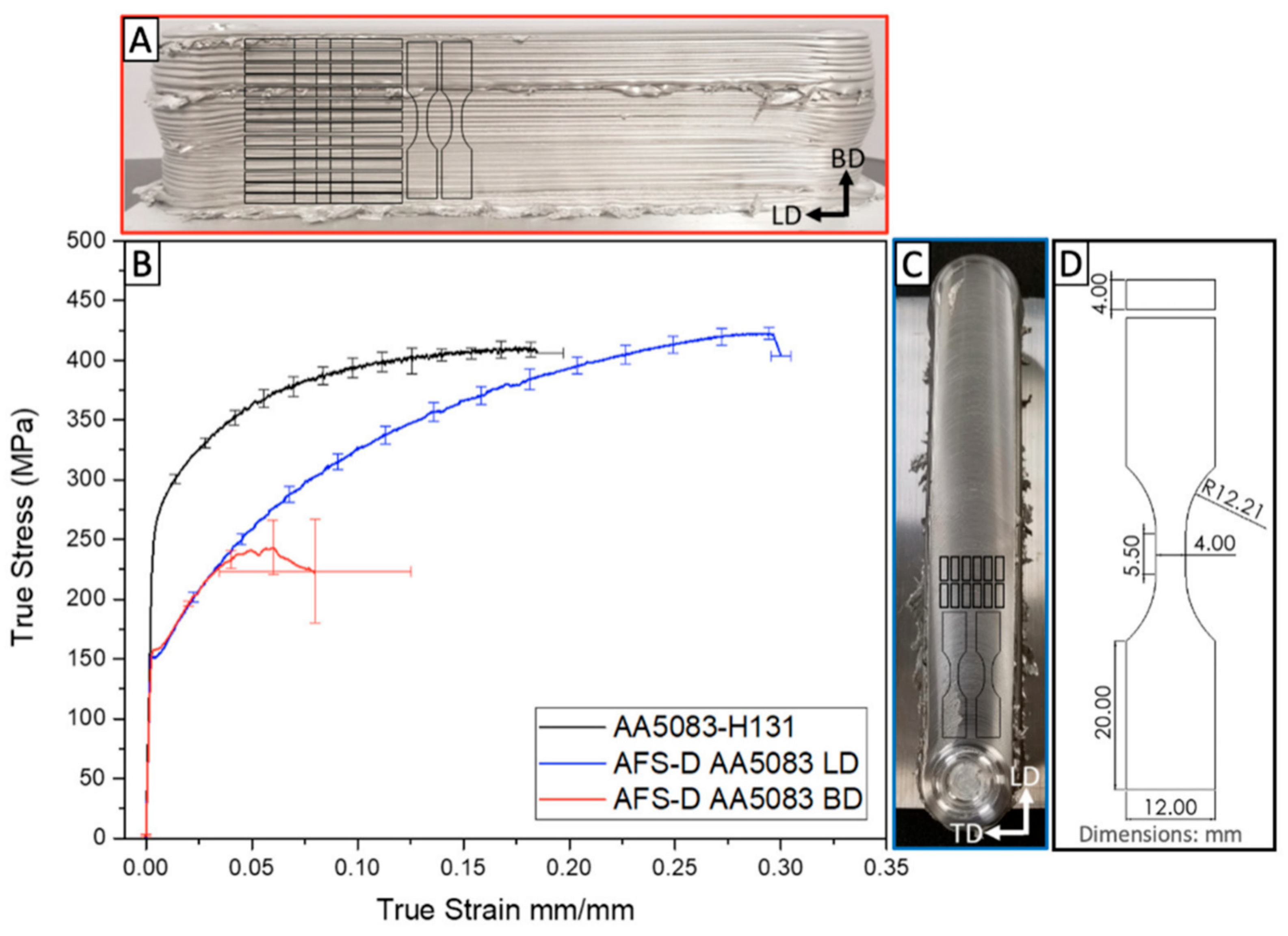
| Material (Direction) | E (GPa) | YS (MPa) | UTS (MPa) | EL (%) |
|---|---|---|---|---|
| AA5083-H131 [34] | 82.9 ± 0.9 | 273.7 ± 1.0 | 410 ± 6.1 | 0.15 ± 0.024 |
| AA5083-H131(LD) [34] | 70.8 ± 5.2 | 151.3 ± 1.7 | 431.3 ± 1.96 | 0.30 ± 0.005 |
| AA5083-H131(BD) [34] | 68.9 ± 5.9 | 157.7 ± 1.2 | 246.2 ± 45.9 | 0.08 ± 0.045 |
| Material (Direction) | YS (MPa) | UTS (MPa) | EL (%) | Average Grain Size (μm) |
|---|---|---|---|---|
| WE43-T5 [67] | 265 | 335 | 19 | 13 ± 7 |
| WE43 Underaged [67] | 138 | 235 | 15 | 112 ± 55 |
| WE43-T6 [67] | 159 | 243 | 15 | 114 ± 58 |
| WE43 AFSD (BD) [66] | 200.8 ± 6.7 | 264.7 ± 10.8 | 11.0 ± 2.5 | 3.7 ± 3.3 |
| WE43 AFSD (TD) [66] | 230.0 ± 12.8 | 283.0 ± 6.1 | 11.7 ± 1.1 | |
| WE43 AFSD (LD) [66] | 213.8 ± 7.5 | 268.5 ± 3.4 | 13.8 ± 2.4 |
| Feedstock | Print Head | Key Conclusions |
|---|---|---|
| AA2014, Rod [9] | Consumable | Huge flash; rough top surface. |
| SS304, Rod [11] | Consumable | Poor interface bonding. |
| AA6061, Rod [14] | Non-consumable | Good interfacial bonding. |
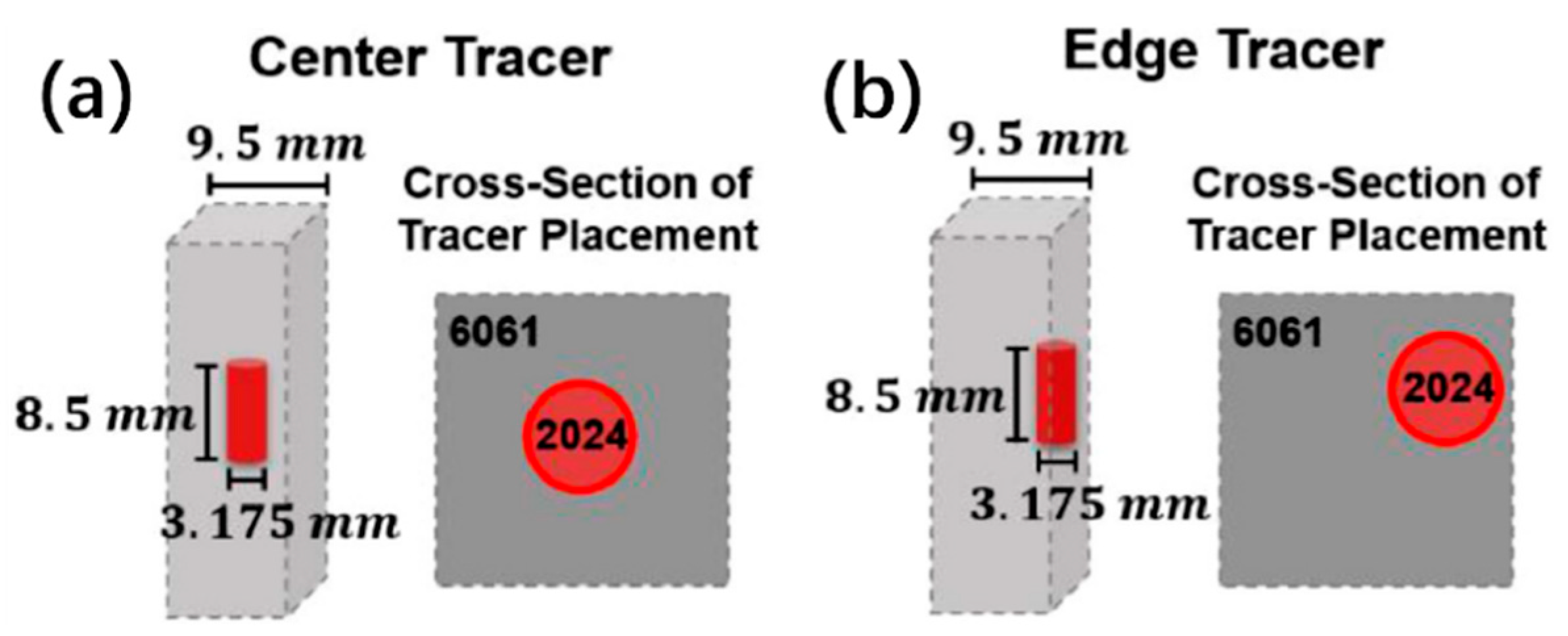
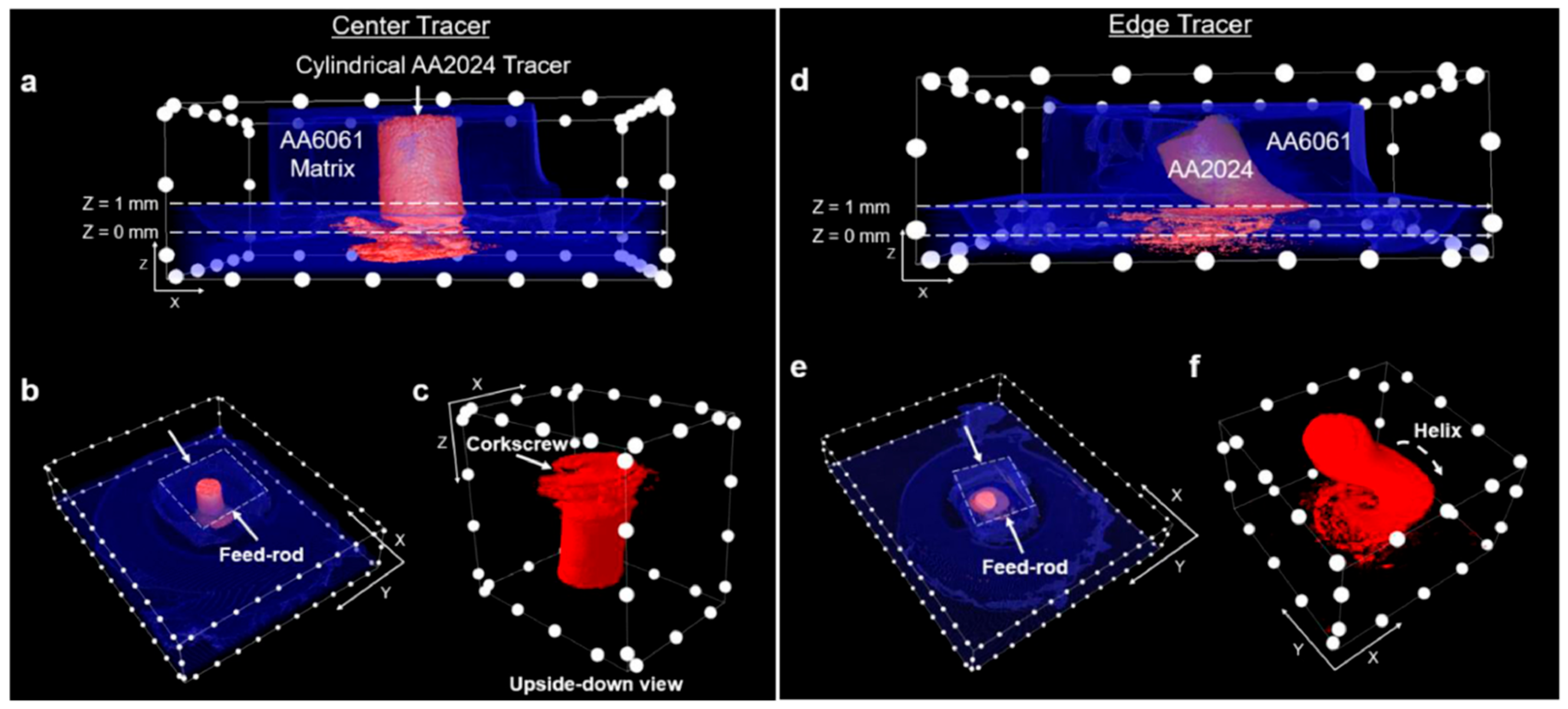
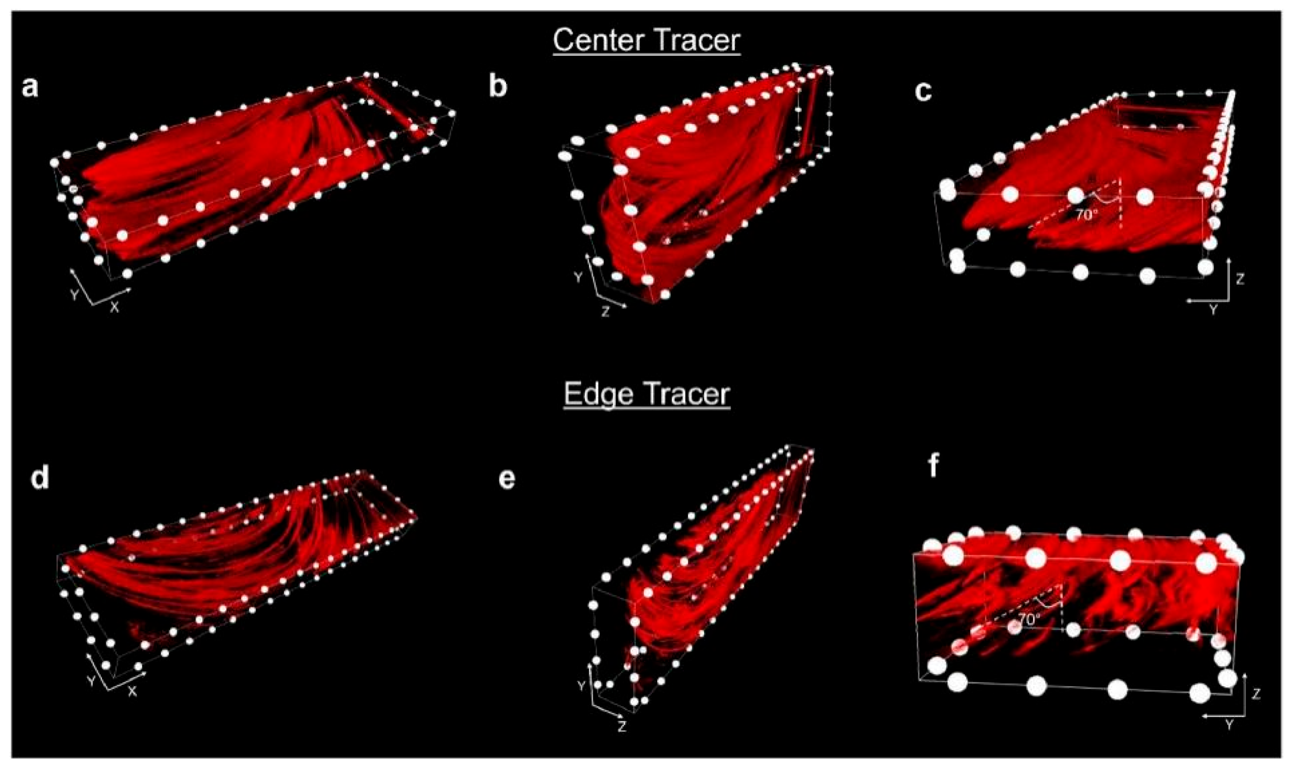
| AA2024, Rod [15,16] | Non-consumable | Non-planar interface; fin and serration structures; material flow and shearing. |
| AA6061, Rod [17] | Non-consumable | No bonding when the layer thickness was too large. |
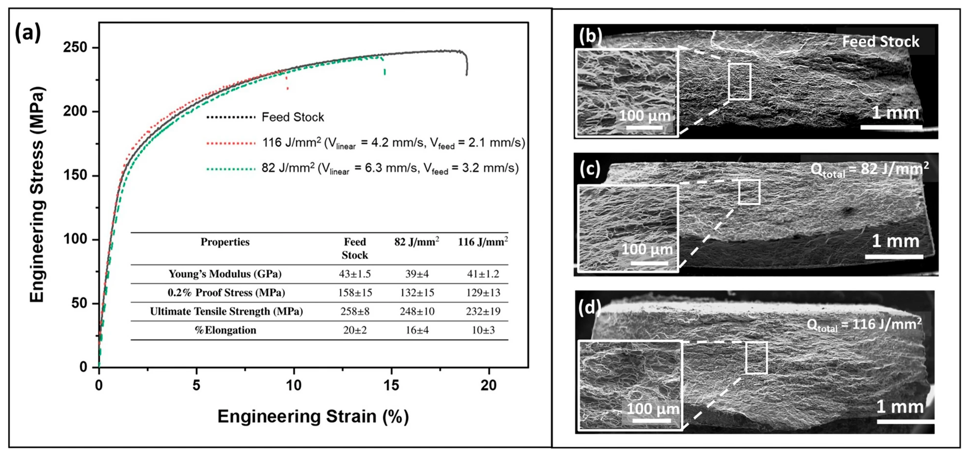
| WE43, Powder [18] | Non-consumable | Powder jammed in the print head; weaker mechanical properties than rod as feedstock. |
| AA5083, Chip [28] | Non-consumable | Increased UTS and fatigue life. |
| AA4043, Wire [29] | Non-consumable | Better macroscopic morphology. |
| AA6061, Wire [30] | Non-consumable | Improved the flexibility of AFSD. |
| IN625, Rod [31] | Non-consumable | Grain size refined. |
| AA2195, Rod [32] | Non-consumable | Superior mechanical properties at the top layer. |
| AA2219, Rod [33] | Non-consumable | Dissolution of θ′, replaced by θ. |
| AA5083, Rod [34,35] | Non-consumable | YS, UTS, and EL decreased in BD; improvement after compression deformation. |
| AA6061, Rod [36] | Non-consumable | Properties close to feedstock after heat treatment. |
| AA6061, Rod [38,39,40,41] | Non-consumable | The lower the rotation speed and the smaller the layer thickness, the finer the grain size. |
| AA6061, Rod [43,44] | Non-consumable | Location dependence of residual stress. |
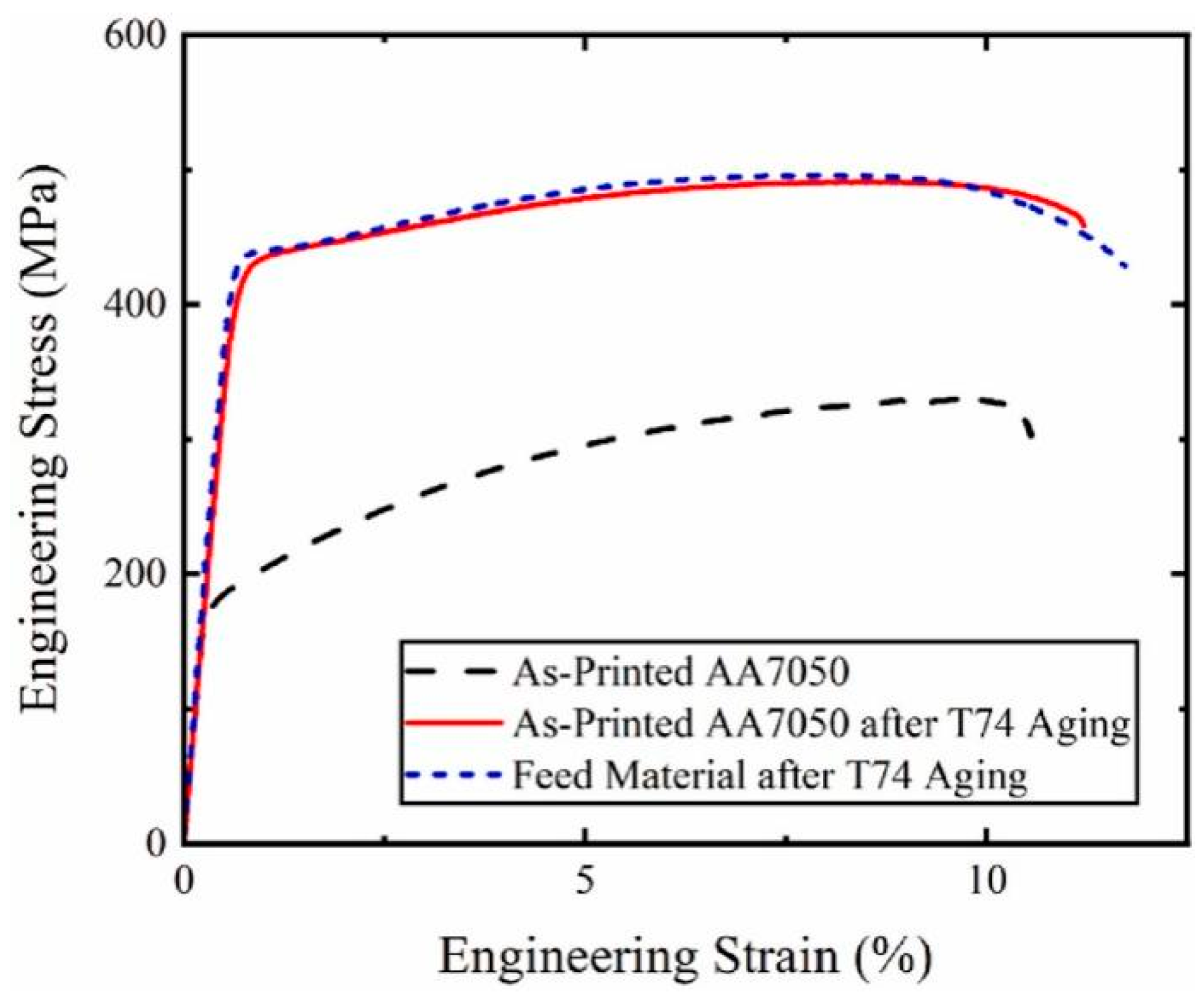
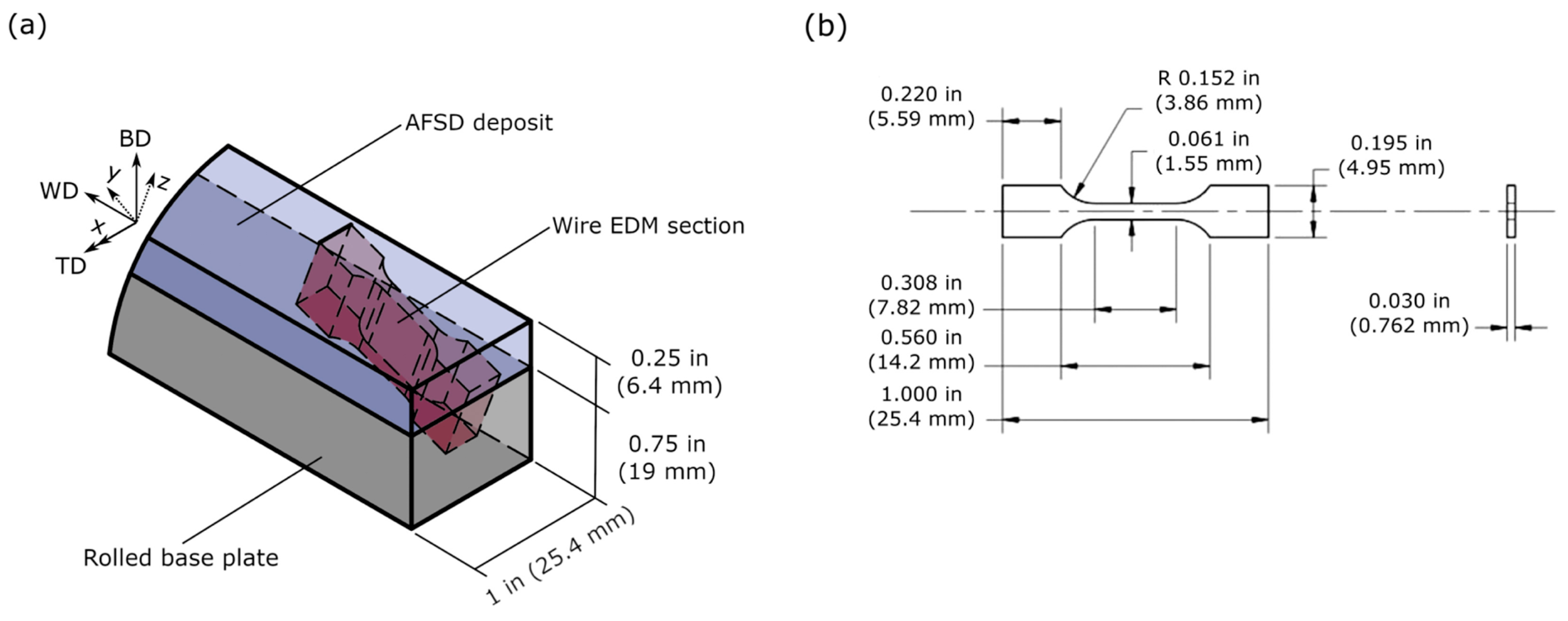
| AA7075, Rod [51] | Non-consumable | Forging-like tensile properties after T74. |
| TiB2/AA7050, Rod [52] | Non-consumable | Evenly dispersed TiB2. |
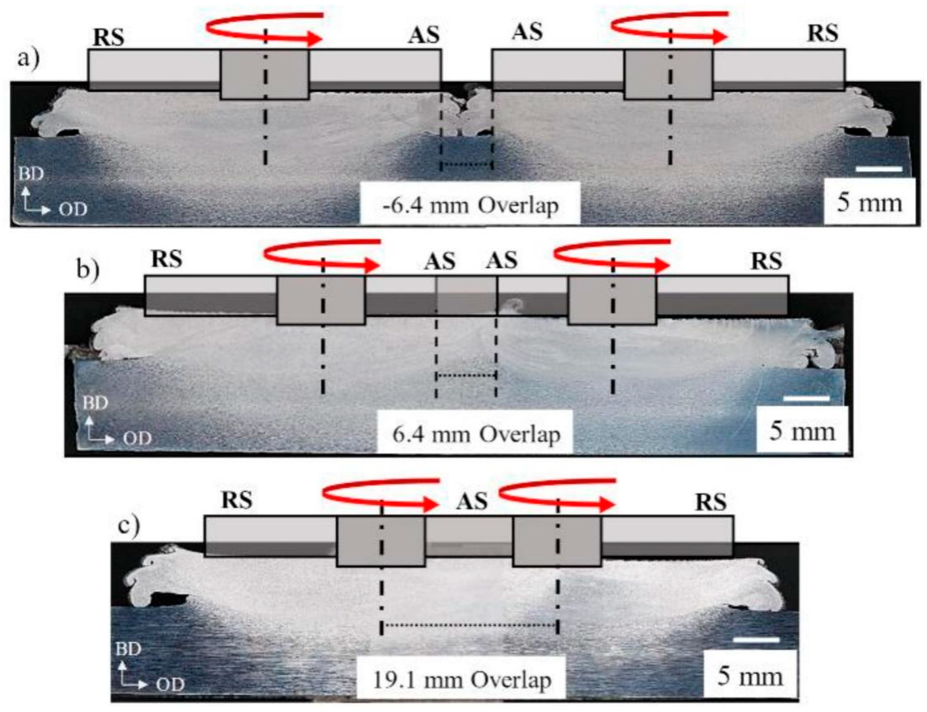
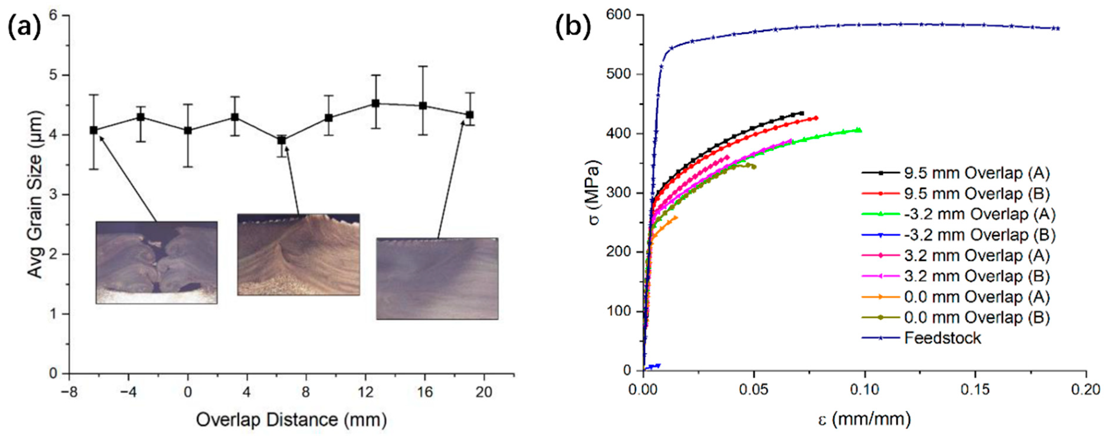
| AA7075, Rod [53] | Non-consumable | As the amount of overlapping increased, the ductility of the material also enhanced. |
| AZ31, Rod [55,63] | Non-consumable | Enhanced the texture intensity, microstructures, and mechanical properties similar to forging ones. |
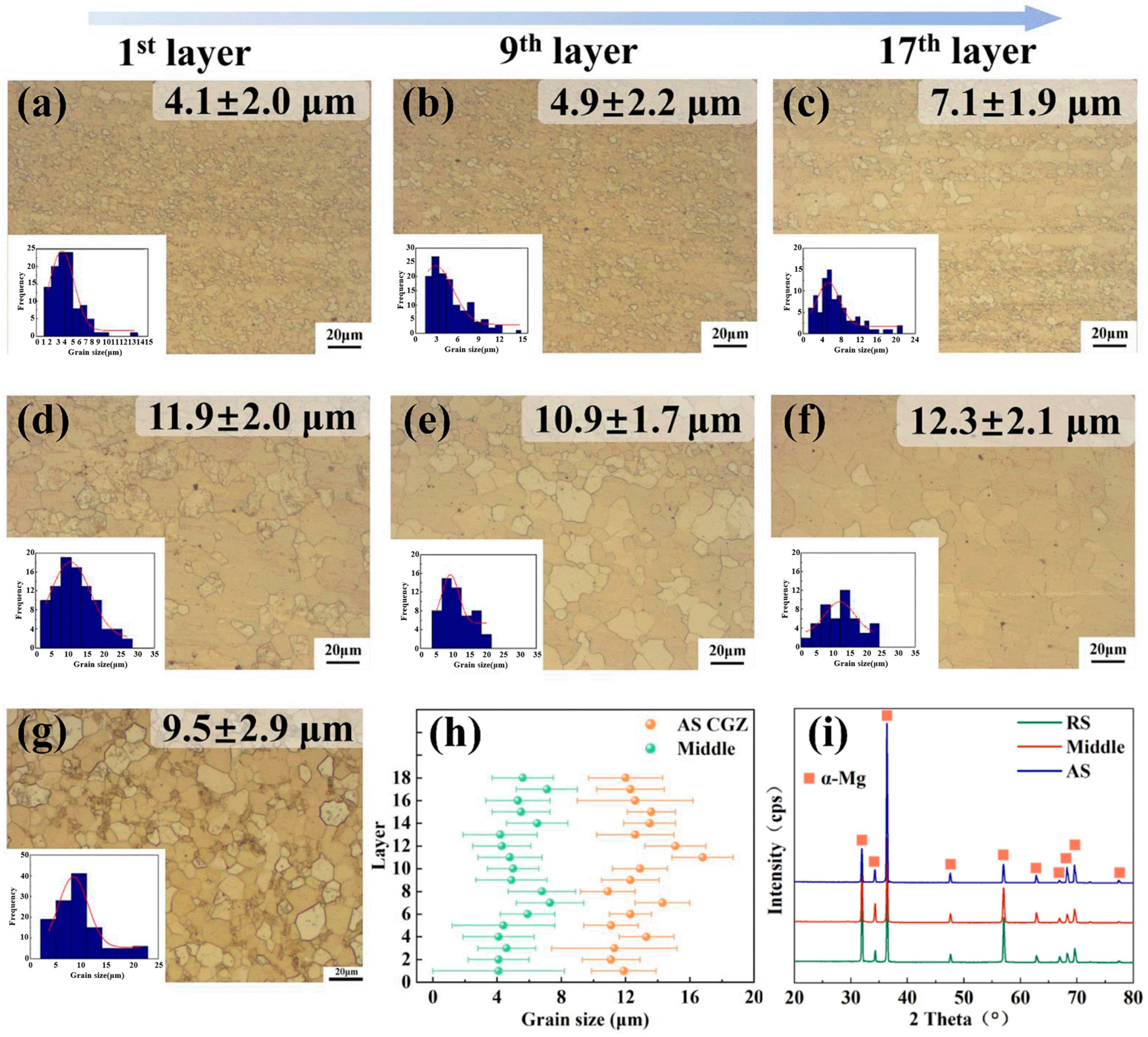
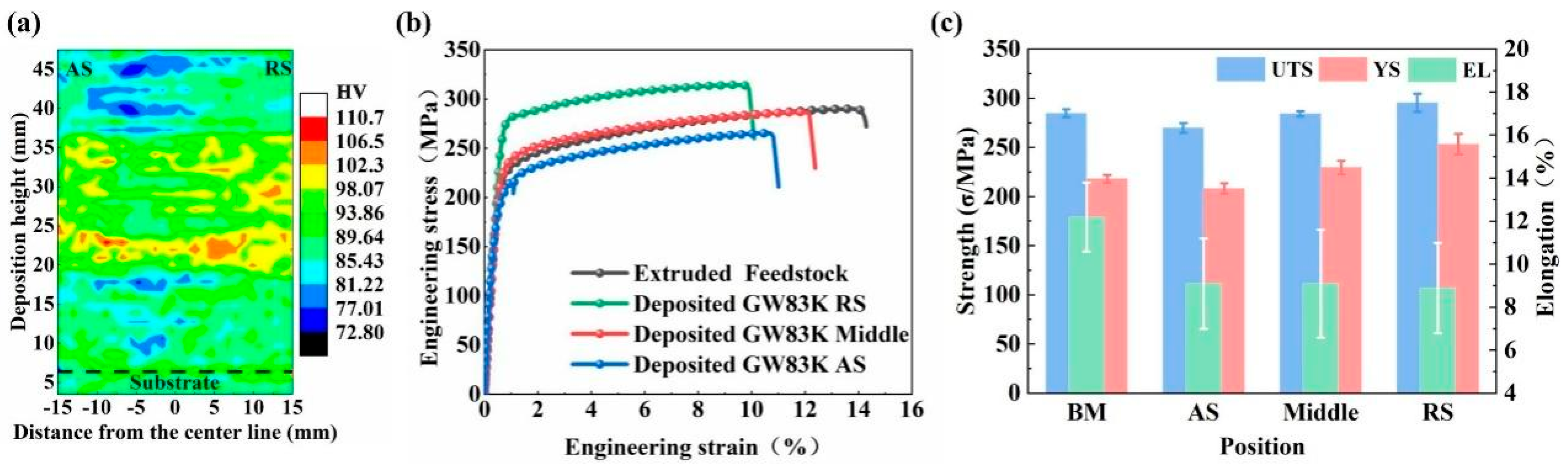
| GW83, Rod [64] | Non-consumable | Grain size and mechanical properties are not uniformly distributed across the width. |
| WE43, Rod [65,66] | Non-consumable | Decreased fatigue life under low-cycle conditions; performance under high-cycle conditions similar to forgings; better YS and UTS than underaged and T6 samples. |
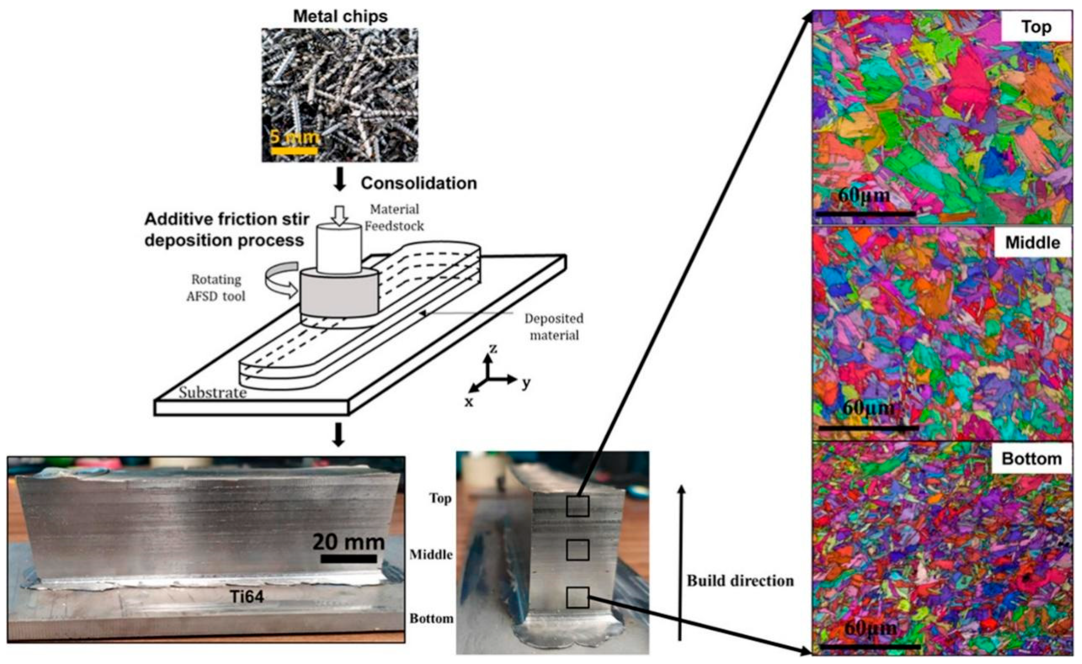
| Ti64, Rod [68] | Non-consumable | EL of 7 ± 1%, YS of 1050 ± 25 MPa, and UTS of 1140 ± 20 MPa. |
| Ti64, Rod [69] | Non-consumable | “Basket weave” shape α-Ti in the prior β grains of 25–50 μm. |
| SS316, Rod [70] | Non-consumable | Formation of a gradient in twinning and martensitic phases following deformation. |
| DSS2507, Rod [71] | Non-consumable | High dependence on machinal properties. |
Disclaimer/Publisher’s Note: The statements, opinions and data contained in all publications are solely those of the individual author(s) and contributor(s) and not of MDPI and/or the editor(s). MDPI and/or the editor(s) disclaim responsibility for any injury to people or property resulting from any ideas, methods, instructions or products referred to in the content. |
© 2024 by the authors. Licensee MDPI, Basel, Switzerland. This article is an open access article distributed under the terms and conditions of the Creative Commons Attribution (CC BY) license (https://creativecommons.org/licenses/by/4.0/).
Share and Cite
Dong, X.; Zhou, M.; Geng, Y.; Han, Y.; Lei, Z.; Chen, G.; Shi, Q. Recent Advances in Additive Friction Stir Deposition: A Critical Review. Materials 2024, 17, 5205. https://doi.org/10.3390/ma17215205
Dong X, Zhou M, Geng Y, Han Y, Lei Z, Chen G, Shi Q. Recent Advances in Additive Friction Stir Deposition: A Critical Review. Materials. 2024; 17(21):5205. https://doi.org/10.3390/ma17215205
Chicago/Turabian StyleDong, Xinze, Mengran Zhou, Yingxin Geng, Yuxiang Han, Zhiguo Lei, Gaoqiang Chen, and Qingyu Shi. 2024. "Recent Advances in Additive Friction Stir Deposition: A Critical Review" Materials 17, no. 21: 5205. https://doi.org/10.3390/ma17215205
APA StyleDong, X., Zhou, M., Geng, Y., Han, Y., Lei, Z., Chen, G., & Shi, Q. (2024). Recent Advances in Additive Friction Stir Deposition: A Critical Review. Materials, 17(21), 5205. https://doi.org/10.3390/ma17215205