
Epoxy Composites with Post-Production Gray Cast-Iron Powders

 , , and
Abstract
:1. Introduction
2. Materials and Methods
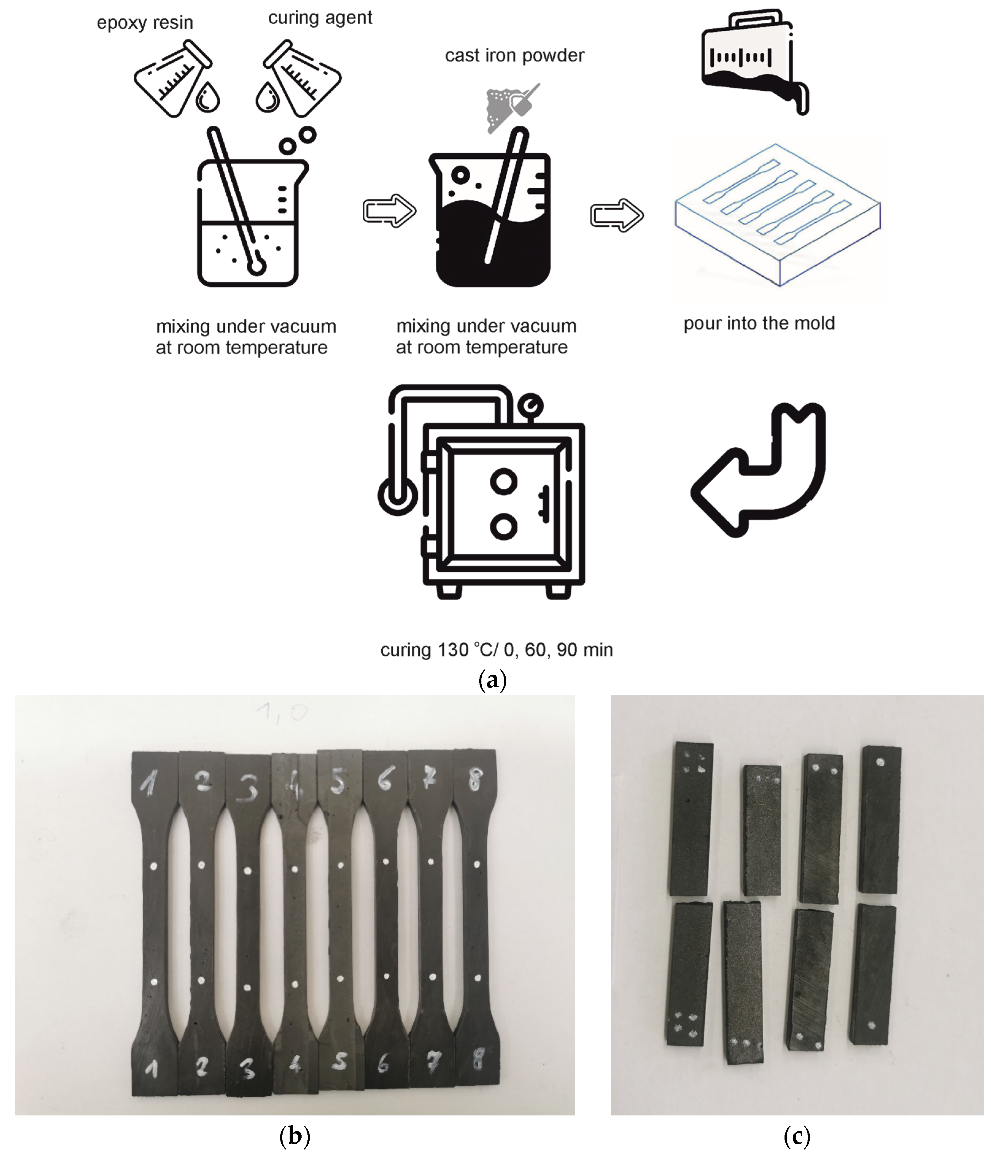
2.1. Materials and Processing
2.2. Methods
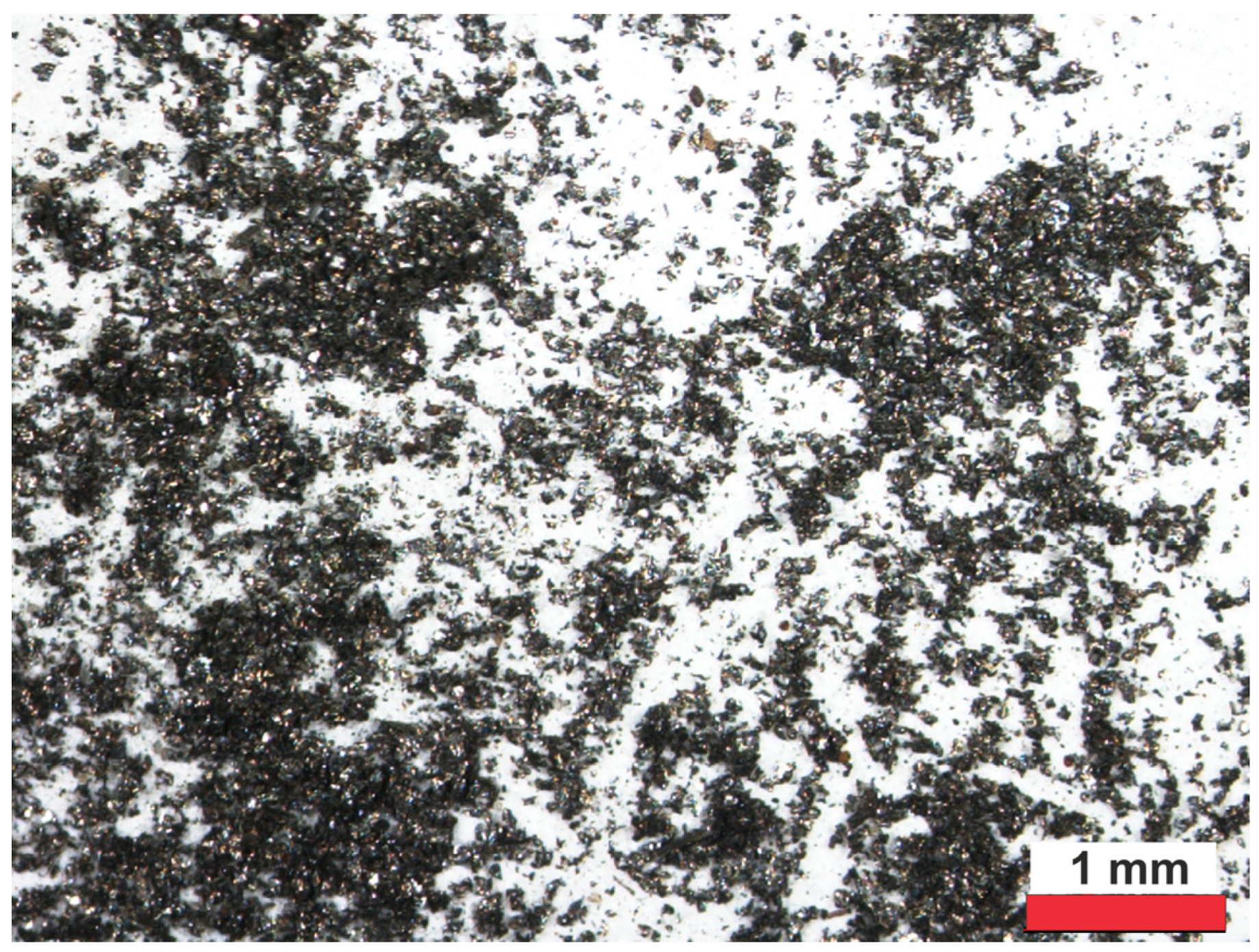
2.2.1. Characteristics of Gray Cast-Iron Powders
2.2.2. Characterization of Matrix Material Components and Performance Evaluation
2.2.3. Microstructural Characterization of the GCI/Epoxy-Based Composites
2.2.4. Mechanical Properties
2.2.5. Corrosion Testing
2.2.6. Testing the Thermal Resistance
3. Results
3.1. Characterization and Performance Evaluation
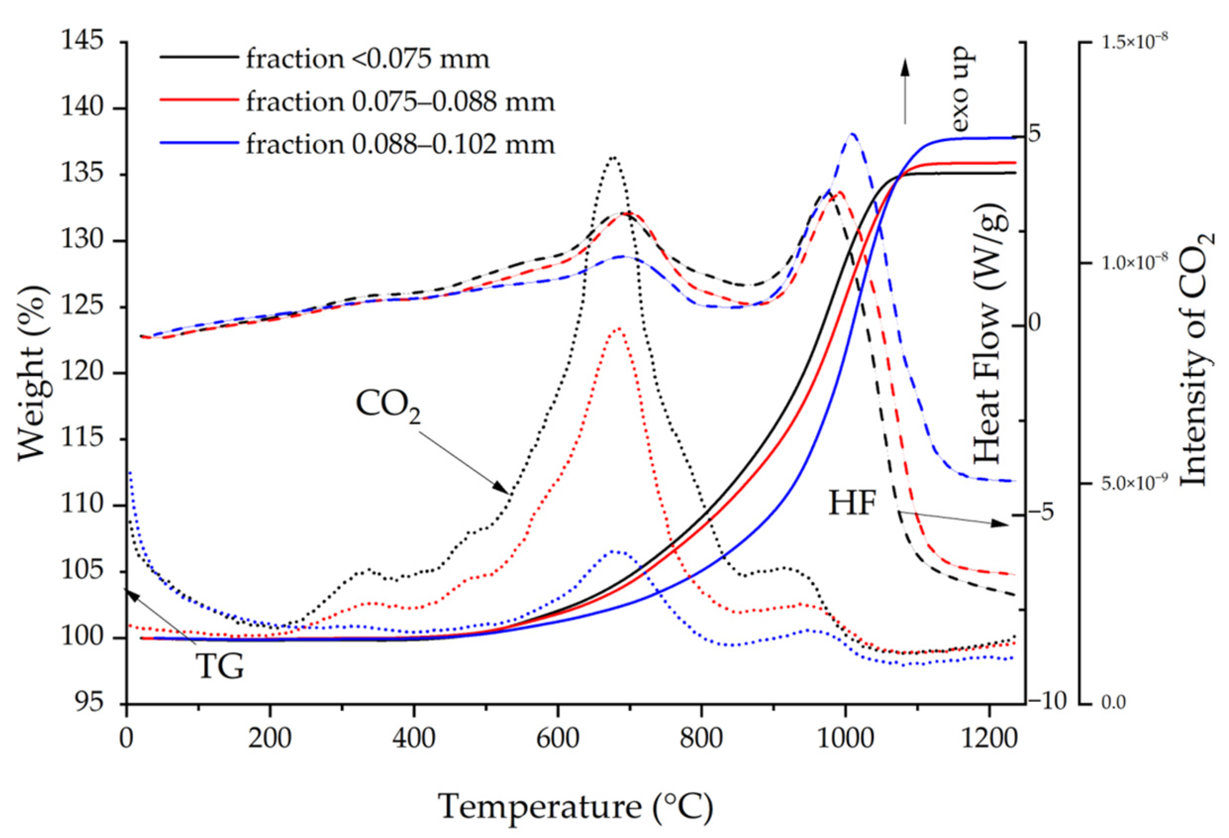
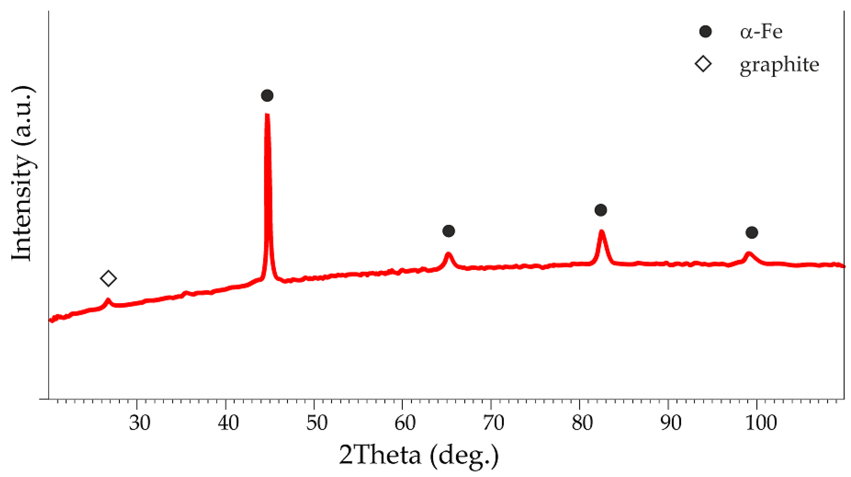
3.1.1. Characterization of the Gray Cast-Iron Powder
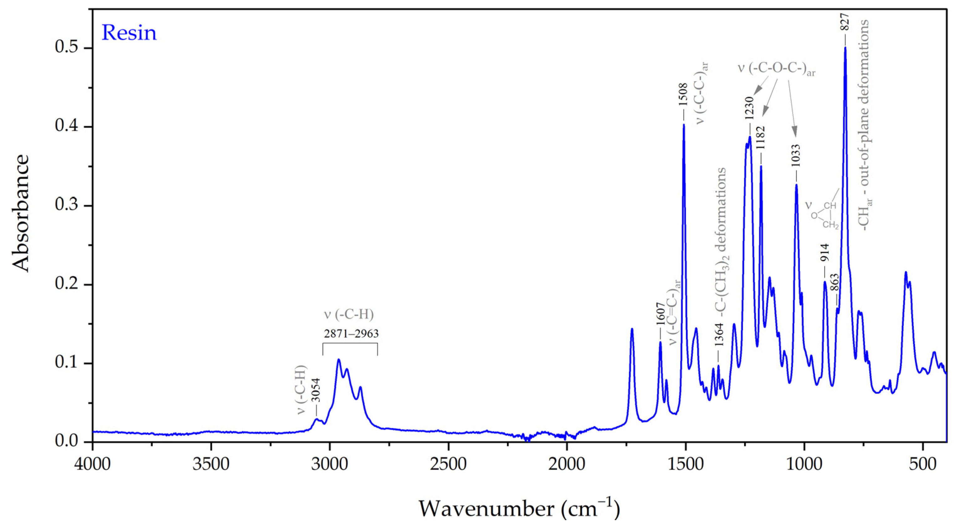
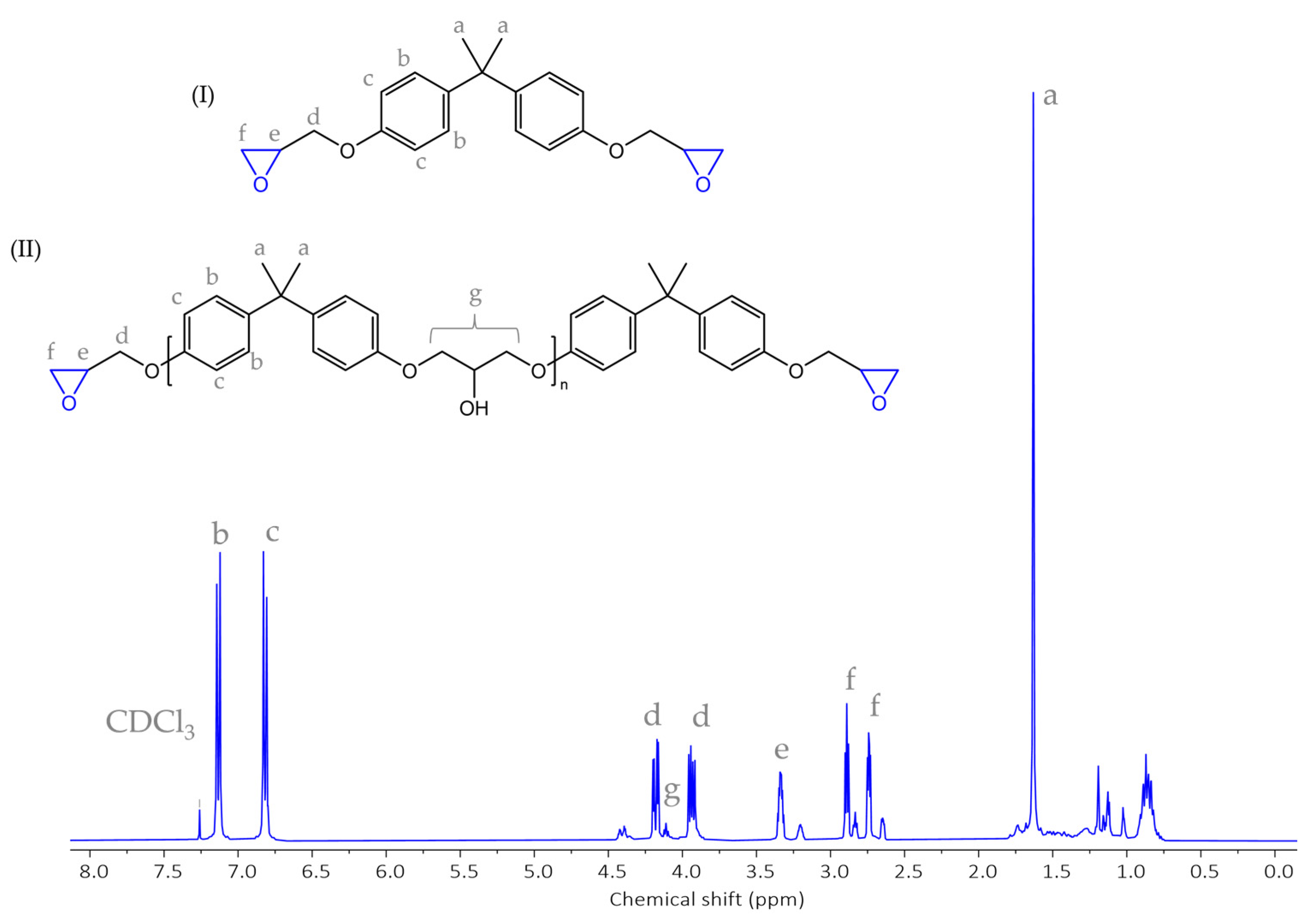
3.1.2. Characteristics of an Epoxy System
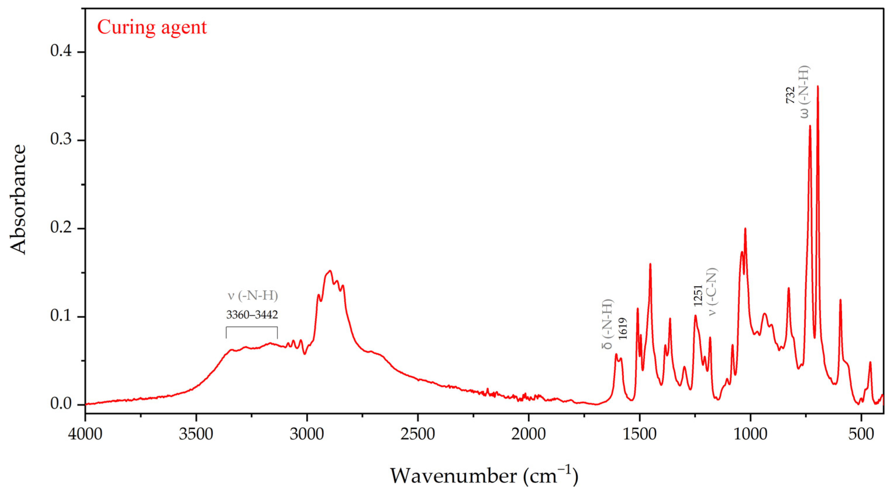
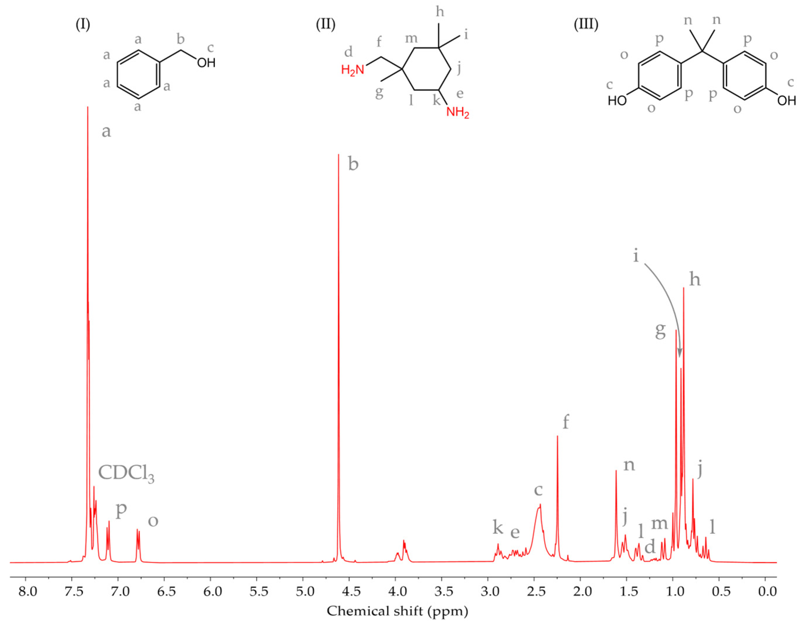
3.1.3. Characteristics of an Epoxy Resin and a Curing Agent
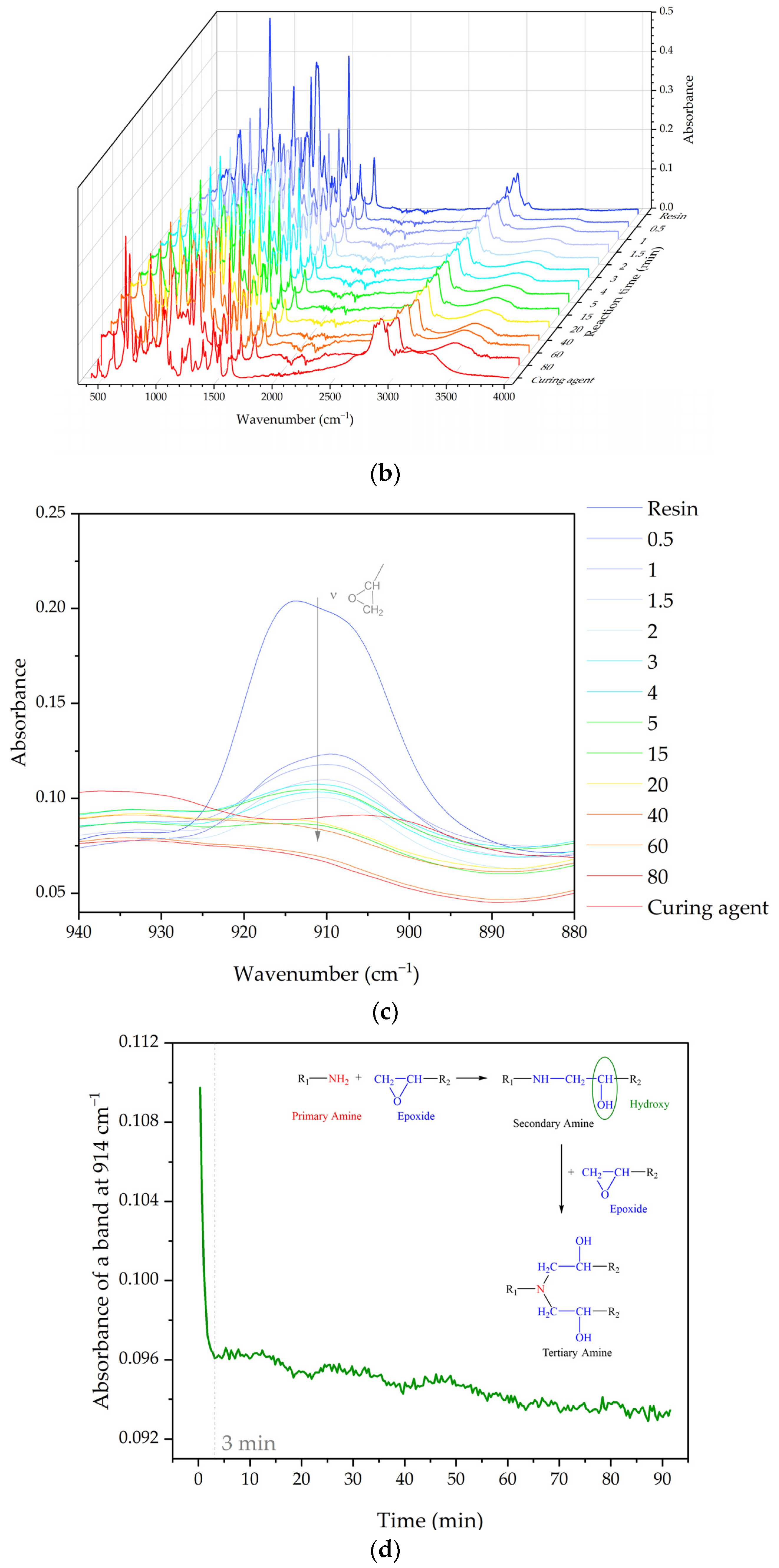
3.1.4. Cure Monitoring and Characterization
3.2. Conditions of the Heat Treatment Process of GCI/Epoxy-Based Composites
- ✓
- heated to 130 °C, not soaked, samples marked with the symbol Pr65 2/0,
- ✓
- heated at a temperature of 130 °C for 60 min, samples marked with the symbol Pr65 2/1,
- ✓
- heated at a temperature of 130 °C for 90 min, samples marked with the symbol Pr65 2/1.5.
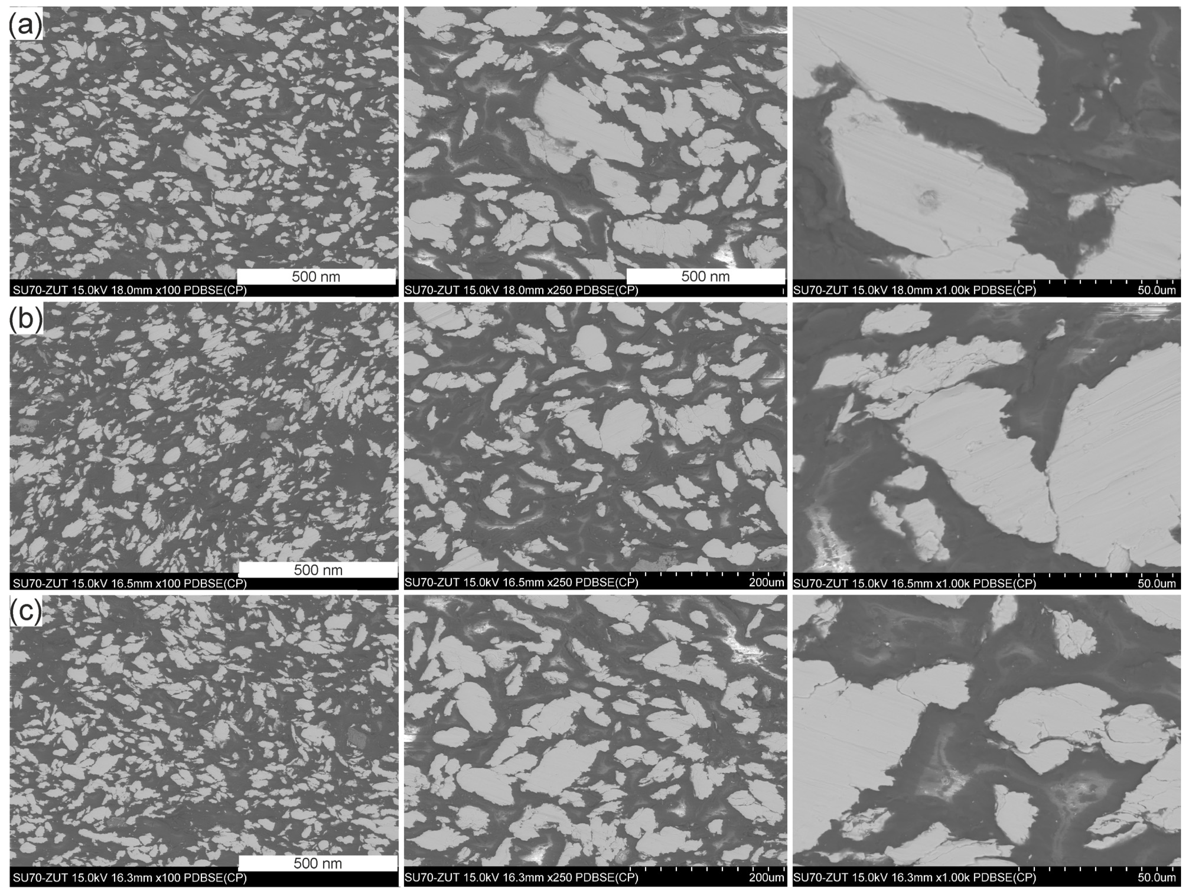
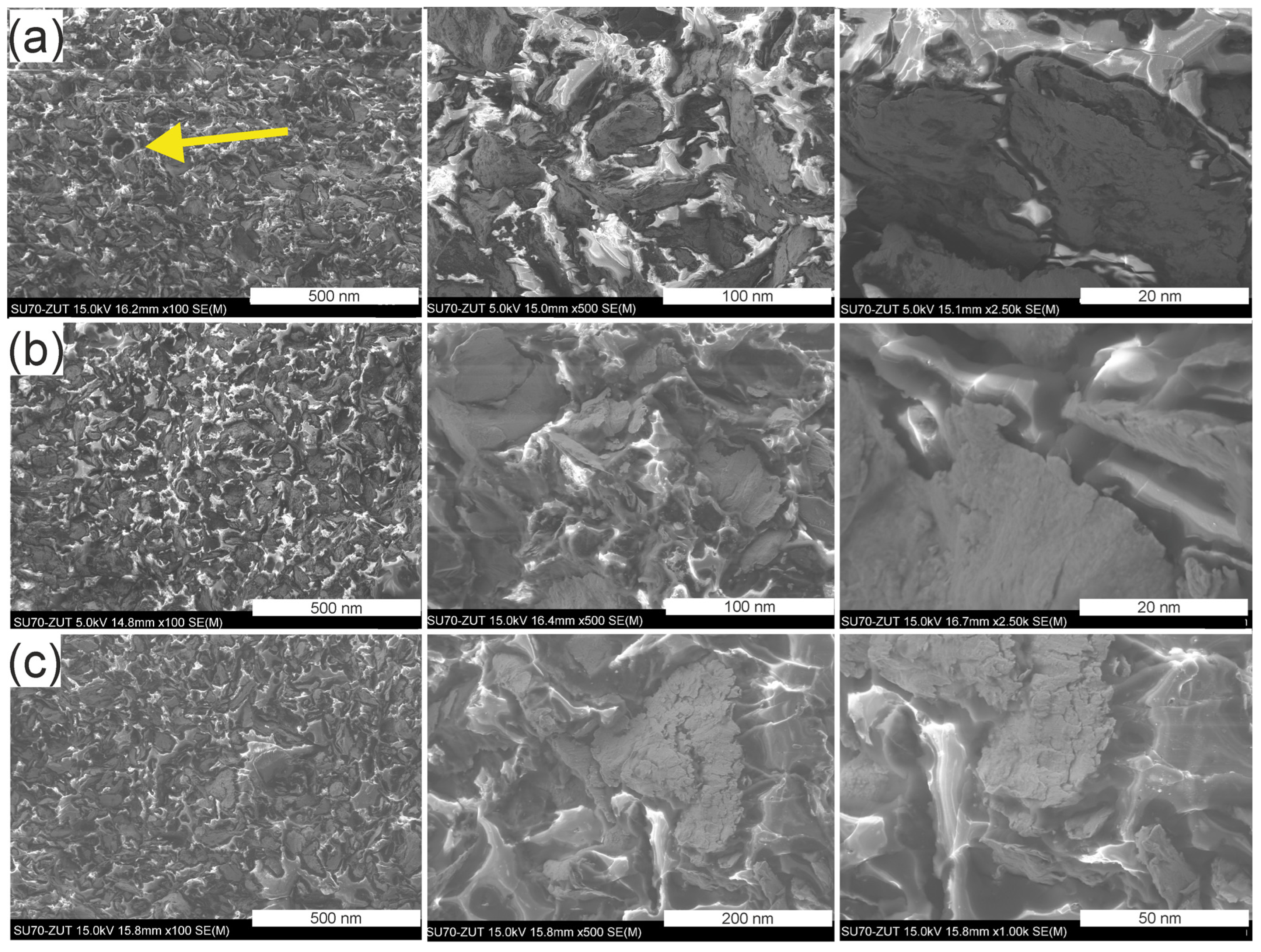
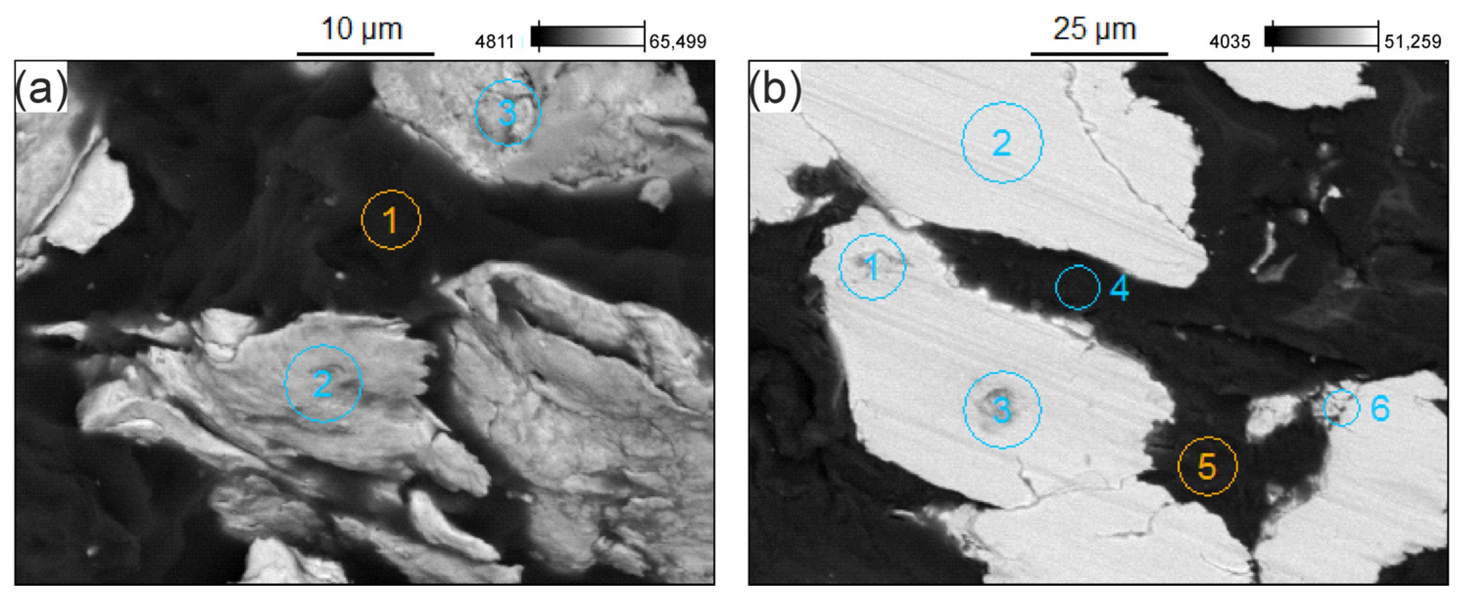
3.3. Microstructure of the GCI/Epoxy-Based Composites
3.4. Mechanical Properties
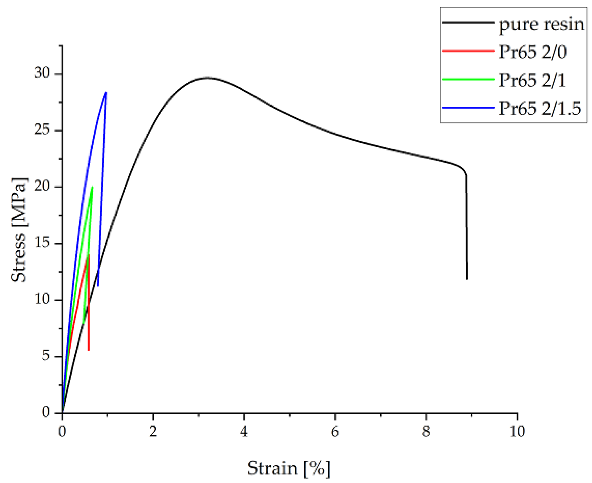
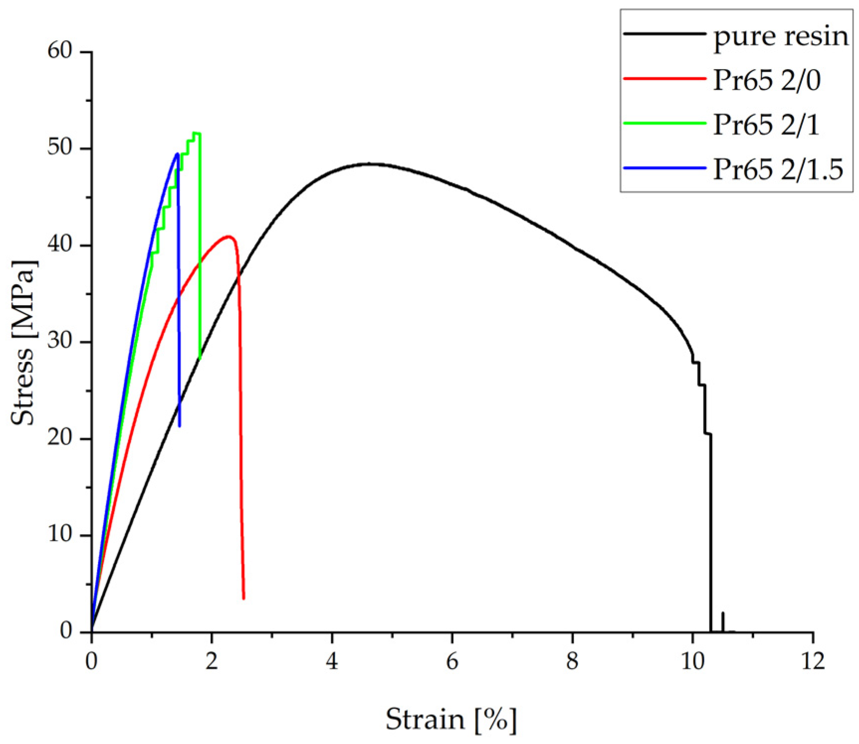
3.4.1. Static Tensile Test
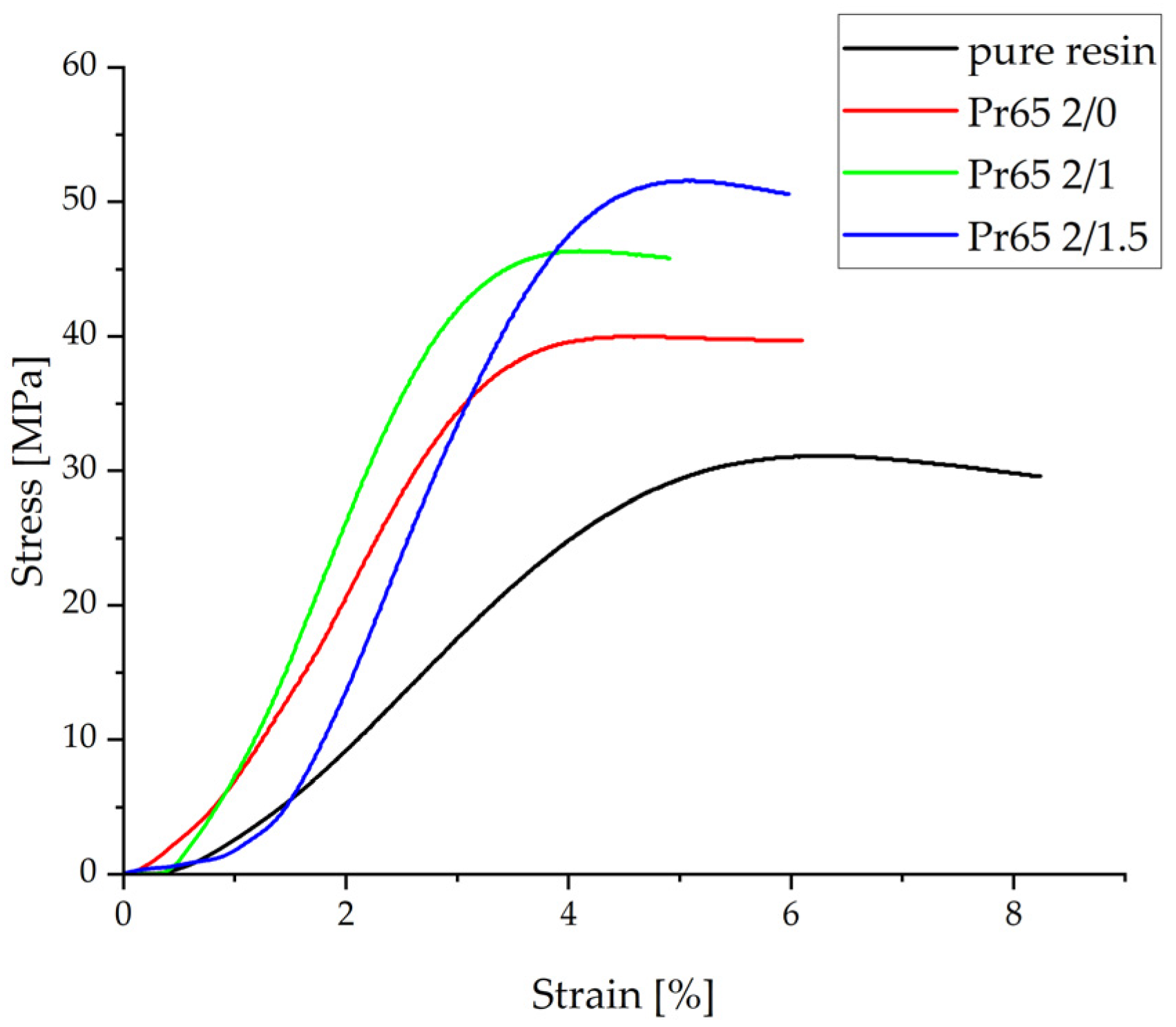
3.4.2. Static Compression Test
3.4.3. Static Flexural Test
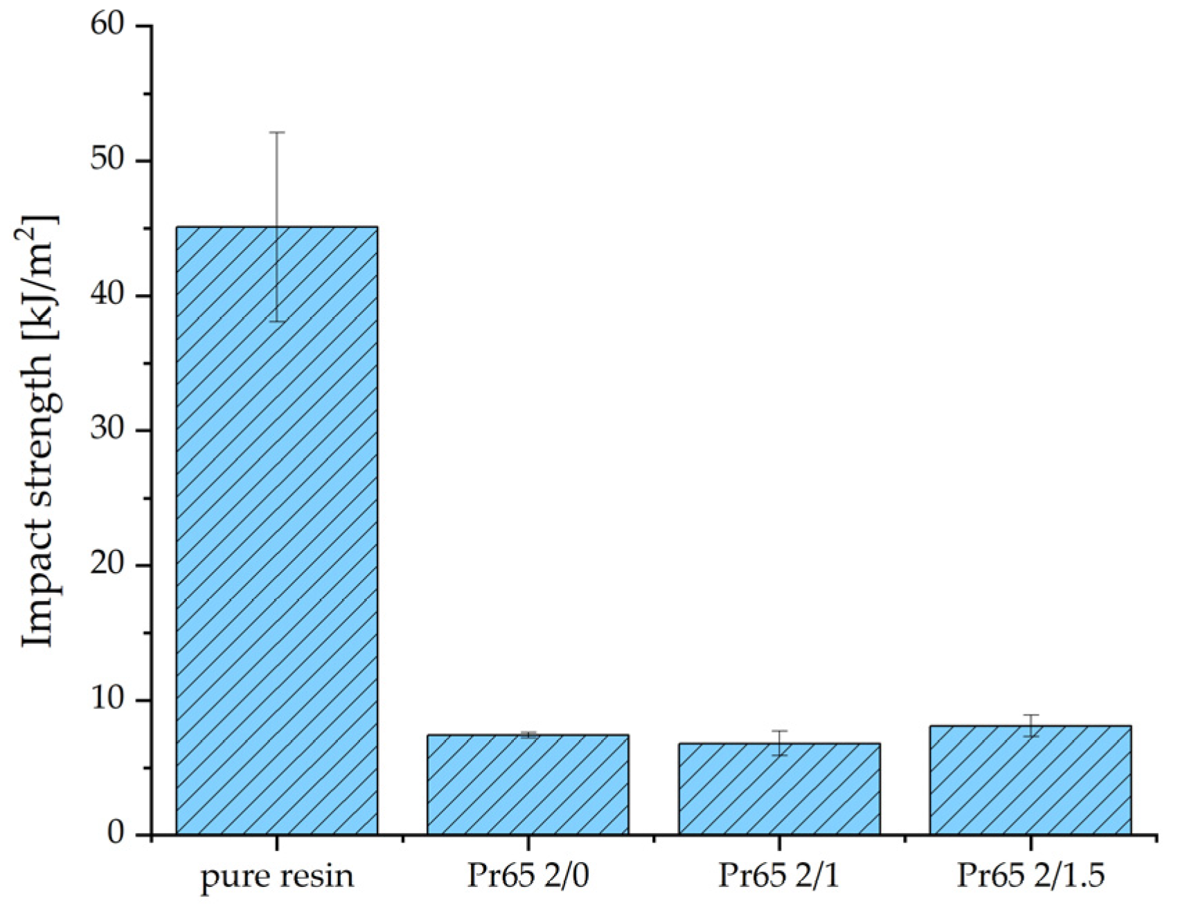
3.4.4. Impact Strength
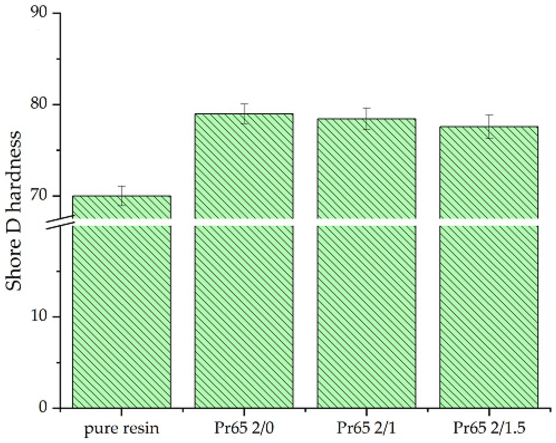
3.4.5. Hardness Test
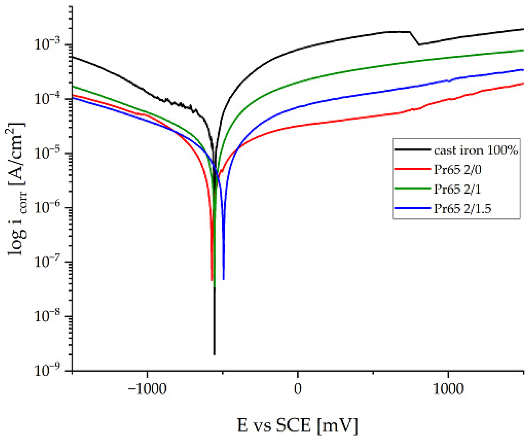
3.4.6. Potentiodynamic Corrosion Testing
3.4.7. Thermal Resistance of Composites
4. Conclusions
- The matrix material was shown to be an epoxy resin based on bisphenol-A-diglycidyl ether (DGEBA)/bisphenol-A, and it is a key component of the investigated system. These results strongly suggested that epoxy resin should be regarded as a mixture of DGEBA and its oligomers, while the curing agent for epoxy resin is isophorone diamine (IPDA). An additional component of the system is benzyl alcohol.
- The resin used was characterized by low viscosity, a relatively high content of volatile substances, and a noticeable concentration of epoxy groups.
- The curing reaction of epoxy resin at 130 °C for the first 3 min was very fast. It took about 70 min to completely harden.
- The epoxy resin had the highest tensile strength, and among the GCI/epoxy-based composites, the composites cured at 130 °C for 60 and 90 min had the highest tensile strength. The composites not heated at 130 °C had the lowest tensile strength value.
- A longer heating time at 130 °C resulted in an increase in tensile strength and Young’s modulus. The lowest value of Young’s modulus was for the epoxy resin.
- The composite heated at 130 °C for the longest time, i.e., 90 min, had the highest compressive strength, while the epoxy resin had the lowest. After removing the compressive force, the material of this composite returned to its original dimensions, while the composite not heated at a 130 °C was destroyed as a result of the static compression test.
- The composite cured at 130 °C for 90 min had the highest value of strength in the static flexural test, while the composite not heated at a temperature of a 130 °C had the lowest. All composites were characterized by a higher value of Young’s modulus compared to the value of the modulus of pure epoxy resin.
- GCI/epoxy-based composites had higher corrosion resistance compared to cast iron. The composite cured at a 130 °C for 90 min had the highest corrosion resistance. The soaking and longer heating time of the composites increased their resistance to electrochemical corrosion. The corrosion rate of cast iron under the measurement conditions was 3.3 times higher than the corrosion rate of the most resistant composite.
- Epoxy resin and all GCI/epoxy-based composites showed high thermal resistance. Their thermal decomposition temperatures exceeded 300 °C. The addition of gray cast-iron powder to the epoxy resin shifted the maximum of the exothermic peak by more than 20 degrees. Epoxy resin was characterized by the highest thermal resistance. The difference between the decomposition temperatures of the composites did not exceed 1.5 degrees. Among the composites, the one cured at 130 °C for 60 min had the best properties, followed by the composite cured at 130 °C for 90 min. The composite not heated at a temperature of 130 °C had the lowest thermal resistance.
- Comparison of the test results of the composites showed that the composite hardened at 130 °C for 90 min had the best mechanical properties. It was characterized by the highest tensile, compressive, and bending strength, the highest impact strength and corrosion resistance, and relatively good thermal resistance. Its tensile strength was similar to the tensile strength of epoxy resin.
- Compared to gray cast iron, GCI/epoxy-based composites were characterized by a much lower weight and higher corrosion resistance. Compared to epoxy resin, composites reinforced with gray cast-iron powders were characterized by higher tensile, compressive, and flexural strength, as well as stiffness. These composites had low impact strengths due to their brittle and stiff behavior. The conducted research showed the possibility of a simple, highly efficient, and cheap method of utilizing of waste cast iron in the form of a powder.
- The best mechanical and corrosion properties were characterized by the composite marked with the symbol Pr65 2/1.5, which was cured at a temperature of 130 °C for 90 min. This composite had a tensile strength of 28.35 MPa, comparable to epoxy resin, and a higher bending strength of 55.4 MPa and compressive strength of 53.8 MPa. This composite was thermally stable, its thermal decomposition temperature reached a value of 327.7 C, and in addition, in tap water, it showed a corrosion rate more than three times lower than cast iron used in practice for the production of water supply fittings.
Author Contributions
Funding
Institutional Review Board Statement
Informed Consent Statement
Data Availability Statement
Conflicts of Interest
References
- Pribulova, A.; Futas, P.; Pavucko, S. Recycling of Wastes from Cast Iron Castings Production. In Proceedings of the International Multidisciplinary Scientific GeoConference Surveying Geology and Mining Ecology Management, SGEM, Albena, Bulgaria, 28 June–7 July 2024; Volume 19, pp. 763–770. [Google Scholar]
- Tayeh, B.A. Utilization of Waste Iron Powder as Fine Aggregate in Cement Mortar. J. Eng. Res. Technol. 2018, 5, 22–27. [Google Scholar]
- Puga, H.; Barbosa, J.; Soares, D.; Silva, F.; Ribeiro, S. Recycling of Aluminium Swarf by Direct Incorporation in Aluminium Melts. J. Mater. Process Technol. 2009, 209, 5195–5203. [Google Scholar] [CrossRef]
- Da Costa, C.E.; Zapata, W.C.; Parucker, M.L. Characterization of Casting Iron Powder from Recycled Swarf. J. Mater. Process. Technol. 2003, 143–144, 138–143. [Google Scholar] [CrossRef]
- Shaibani, M.E.; Ghambari, M. Characterization and Comparison of Gray Cast Iron Powder Produced by Target Jet Milling and High Energy Ball Milling of Machining Scraps. Powder Technol. 2011, 212, 278–283. [Google Scholar] [CrossRef]
- Emadi Shaibani, M.; Eshraghi, N.; Ghambari, M. Sintering of Grey Cast Iron Powder Recycled via Jet Milling. Mater. Des. 2013, 47, 174–178. [Google Scholar] [CrossRef]
- Mamedov, A.T.; Aliev, N.A.; Guliev, A.A. Experimental Reprocessing of Waste Cast-Iron Chips to the Powder Form. Powder Metall. Met. Ceram. 1993, 32, 182–186. [Google Scholar] [CrossRef]
- Abdollahi, H.; Mahdavinejad, R.; Panahi Leavoli, R.; Ghambari, M.; Moradi, M. Investigation and Optimization of Properties of Sintered Iron/Recycled Grey Cast Iron Powder Metallurgy Parts. Proc. Inst. Mech. Eng. B J. Eng. Manuf. 2015, 229, 1010–1020. [Google Scholar] [CrossRef]
- Kjeldsteen, P. Recycling of Cast Iron Swarf by the Powder Metallurgy Technique. Mater. Des. 1982, 3, 335–340. [Google Scholar] [CrossRef]
- Takeuchi, E.; Matsunaga, M.; Nakagawa, T.; Dai, F.S.; Ra, H.-Y. Friction and Wear of Sintered Cast Iron Products. Wear 1982, 75, 303–312. [Google Scholar] [CrossRef]
- Bokii, Y.F. Purification of Metal Powders from Oxide Films in a Jet Mill. Sov. Powder Metall. Met. Ceram. 1982, 21, 81–84. [Google Scholar] [CrossRef]
- Vadiraj, A.; Balachandran, G.; Kamaraj, M.; Kazuya, E. Mechanical and Wear Behavior of Quenched and Tempered Alloyed Hypereutectic Gray Cast Iron. Mater. Des. 2011, 32, 2438–2443. [Google Scholar] [CrossRef]
- Karandikar, D.A. Processing of Cast Iron Scrap from the Diesel Engine Manufacturing Industry by Powder Metallurgy Techniques. Resour. Conserv. Recycl. 1991, 5, 61–71. [Google Scholar] [CrossRef]
- Thakur, A.; Bhatia, O.S. Tribological Performance of Inorganic-Metallic Fiber Reinforced Automotive Brake Friction Materials. Int. Res. J. Eng. Technol. 2016, 3, 443–448. [Google Scholar]
- Kumar, M.; Bijwe, J. NAO Friction Materials with Various Metal Powders: Tribological Evaluation on Full-Scale Inertia Dynamometer. Wear 2010, 269, 826–837. [Google Scholar] [CrossRef]
- Bank, L.C. Composites for Construction: Structural Design with FRP Materials; John Wiley and Sons: Hoboken, NJ, USA, 2007; ISBN 0471681261. [Google Scholar]
- Podolsky, Z.; Liu, J.; Dinh, H.; Doh, J.H.; Guerrieri, M.; Fragomeni, S. State of the Art on the Application of Waste Materials in Geopolymer Concrete. Case Stud. Constr. Mater. 2021, 15, e00637. [Google Scholar] [CrossRef]
- Nongnuang, T.; Jitsangiam, P.; Rattanasak, U.; Tangchirapat, W.; Suwan, T.; Thongmunee, S. Characteristics of Waste Iron Powder as a Fine Filler in a High-Calcium Fly Ash Geopolymer. Materials 2021, 14, 2515. [Google Scholar] [CrossRef] [PubMed]
- Wei, X. Research on the Selection of Pipe Materials for Water Supply and Drainage. In E3S Web of Conferences, Proceedings of the 3rd International Conference on Energy Resources and Sustainable Development (ICERSD 2020), Harbin, China, 25–27 December 2020; Anpo, M., Song, F., Eds.; EDP Sciences: Les Ulis, France, 2021; Volume 236, p. 02031. [Google Scholar]
- Fjeldhus, K.S. Selecting Materials for Potable Water Pipes from an Environmental Perspective—Life Cycle Assessments of Four Chosen Pipe Materials. Master’s Thesis, Norwegian University of Life Sciences, Ås, Norway, 2012. Available online: https://nmbu.brage.unit.no/nmbu-xmlui/bitstream/handle/11250/188981/fjeldhus_2012.pdf?sequence=1&isAllowed=y (accessed on 16 May 2024).
- Czapla, A.; Ganesapillai, M.; Drewnowski, J. Composite as a Material of the Future in the Era of Green Deal Implementation Strategies. Processes 2021, 9, 2238. [Google Scholar] [CrossRef]
- Kumar Sharma, A.; Bhandari, R.; Sharma, C.; Krishna Dhakad, S.; Pinca-Bretotean, C. Polymer Matrix Composites: A State of Art Review. Mater. Today Proc. 2022, 57, 2330–2333. [Google Scholar] [CrossRef]
- Sudheer, M. Study of Wear Behaviour of Recycled Metal Powder Filled Epoxy Composites Using Factorial Analysis. Am. J. Mater. Sci. 2016, 6, 82–87. Available online: http://article.sapub.org/10.5923.c.materials.201601.16.html (accessed on 16 May 2024). [CrossRef]
- Sławski, S.; Woźniak, A.; Bazan, P.; Mrówka, M. The Mechanical and Tribological Properties of Epoxy-Based Composites Filled with Manganese-Containing Waste. Materials 2022, 15, 1579. [Google Scholar] [CrossRef]
- Madugu, I.A.; Abdulwahab, M.; Aigbodion, V.S. Effect of Iron Fillings on the Properties and Microstructure of Cast Fiber-Polyester/Iron Filings Particulate Composite. J. Alloys Compd. 2009, 476, 807–811. [Google Scholar] [CrossRef]
- Pascault, J.P.; Williams, R.J.J. Epoxy Polymers: New Materials and Innovations; Wiley‐VCH Verlag GmbH & Co. KGaA: Weinheim, Germany, 2010; ISBN 9783527324804. [Google Scholar]
- Kurahatti, R.V.; Suredranathan, A.O.; Kori, S.A.; Ramesh Kumar, A.V.; Mordina, B.; Mallapur, D.G. Friction and Dry Sliding Wear Behaviour of Ni Filled Epoxy Nanocomposite. Tribol.-Mater. Surf. Interfaces 2011, 5, 49–52. [Google Scholar] [CrossRef]
- Kumar, M.; Bijwe, J. Optimized Selection of Metallic Fillers for Best Combination of Performance Properties of Friction Materials: A Comprehensive Study. Wear 2013, 303, 569–583. [Google Scholar] [CrossRef]
- Sharma, S.; Bijwe, J.; Kumar, M. Comparison between Nano- and Micro-Sized Copper Particles as Fillers in NAO Friction Materials. Nanomater. Nanotechnol. 2013, 3. [Google Scholar] [CrossRef]
- Brêda, C.; Dencheva, N.; Lanceros-Méndez, S.; Denchev, Z. Preparation and Properties of Metal-Containing Polyamide Hybrid Composites via Reactive Microencapsulation. J. Mater. Sci. 2016, 51, 10534–10554. [Google Scholar] [CrossRef]
- Kolesnikov, I.V. Metal–Polymer Tribosystems: Basic Recommendations for Creating Composites. J. Frict. Wear 2016, 37, 507–511. [Google Scholar] [CrossRef]
- Rangadhara Chary, V.; Srinivasa Rao, T.; Mohan, M.K. Effect of Nanocrystalline TiB2 Addition on Properties of Copper Powder Reinforced Epoxy Composites. Trans. Indian. Inst. Met. 2017, 70, 2695–2706. [Google Scholar] [CrossRef]
- Boczkowska, A.; Kapuściński, J.; Puciłowski, K.; Wojciechowski, S. Composites; House of the Warsaw University of Technology: Warsaw, Poland, 2000. [Google Scholar]
- Ji, Y.; Bao, J.; Tuttle, M.E.; Ge, S.; Yin, Y.; Hu, D. Influence of Magnetic Powders on the Tribological Performance of a Novel Magnetic Brake Material. Compos. Interfaces 2017, 24, 399–415. [Google Scholar] [CrossRef]
- Tsetlin, M.B.; Teplov, A.A.; Belousov, S.I.; Chvalun, S.N.; Golovkova, E.A.; Krasheninnikov, S.V.; Golubev, E.K.; Pichkur, E.B.; Dmitryakov, P.V.; Buzin, A.I. Composite Material Based on Polytetrafluoroethylene and Al-Cu-Fe Quasi-Crystal Filler with Ultralow Wear: Morphology, Tribological, and Mechanical Properties. J. Surf. Investig. 2018, 12, 277–285. [Google Scholar] [CrossRef]
- Martorana, B.; Carotenuto, G.; Pullini, D.; Zvezdin, K.; La Peruta, G.; Perlo, P.; Nicolais, L. Preparation of Plastic Ferromagnetic Composite Materials for Magnetic Encoders. Sens. Actuators A Phys. 2006, 129, 176–179. [Google Scholar] [CrossRef]
- Shang, S.; Song, G.; Chu, X.; Zhang, L.; Chang, F. AC and DC Behavior of Finger-Sensing Metal/Polymer Composites at Various Pressures. Compos. Sci. Technol. 2014, 97, 115–120. [Google Scholar] [CrossRef]
- Hsissou, R.; Benhiba, F.; Echihi, S.; Benkhaya, S.; Hilali, M.; Berisha, A.; Briche, S.; Zarrouk, A.; Nouneh, K.; Elharfi, A. New Epoxy Composite Polymers as a Potential Anticorrosive Coatings for Carbon Steel in 3.5% NaCl Solution: Experimental and Computational Approaches. Chem. Data Collect. 2021, 31, 100619. [Google Scholar] [CrossRef]
- Hsissou, R.; Seghiri, R.; Benzekri, Z.; Hilali, M.; Rafik, M.; Elharfi, A. Polymer Composite Materials: A Comprehensive Review. Compos. Struct. 2021, 262, 113640. [Google Scholar] [CrossRef]
- Elhajjar, R.; Law, C.T.; Pegoretti, A. Magnetostrictive Polymer Composites: Recent Advances in Materials, Structures and Properties. Prog. Mater. Sci. 2018, 97, 204–229. [Google Scholar] [CrossRef]
- Pawelec, Z.; Wolszczak, M.; Molenda, J.; Szczepaniak, B. Właściwości Eksploatacyjne Regeneracyjnych Kompozytów Metalopolimerowych Na Osnowie Zmodyfikowanych Żywic Epoksydowych. Probl. Eksploat. 2009, 2, 171–180. [Google Scholar]
- Adeniyi, A.G.; Ighalo, J.O. A Systematic Review of Pure Metals Reinforced Plastic Composites. Iran. Polym. J. 2021, 30, 751–768. [Google Scholar] [CrossRef]
- Bouzat, F.; Darsy, G.; Foucaud, S.; Lucas, R. Group 4 Metal-Containing Polymers: An Overview. Polym. Rev. 2016, 56, 187–224. [Google Scholar] [CrossRef]
- Buketov, A.; Syzonenko, O.; Kruglyj, D.; Cherniavska, T.; Appazov, E.; Klevtsov, K. Investigation of the Influence of the Synthesized Iron-Carbide Mixture on the Adhesive and Mechanical Properties of Epoxy Composites for Parts of Transport Machines. Eng. Technol. Appl. Sci. Res. 2020, 10, 6214–6219. [Google Scholar] [CrossRef]
- Chandra Dubey, S.; Mishra, V.; Sharma, A. A Review on Polymer Composite with Waste Material as Reinforcement. Mater. Today Proc. 2021, 47, 2846–2851. [Google Scholar] [CrossRef]
- Czub, P.; Boncza-Tomaszewski, Z.; Penczek, P.; Pielichowski, J. Chemia i Technologia Żywic Epoksydowych, IV ed.; Wydawnictwa Naukowo-Techniczne: Warsaw, Poland, 2002. [Google Scholar]
- Levchik, S.V.; Weil, E.D. Thermal Decomposition, Combustion and Flame-Retardancy of Epoxy Resins—A Review of the Recent Literature. Polym. Int. 2004, 53, 1901–1929. [Google Scholar] [CrossRef]
- Zaporojtchenko, V.; Strunskus, T.; Behnke, K.; Von Bechtolsheim, C.; Kiene, M.; Faupel, F. Metal/Polymer Interfaces with Designed Morphologies. J. Adhes. Sci. Technol. 2000, 14, 467–490. [Google Scholar] [CrossRef]
- Bhavith, K.; Prashanth Pai, M.; Sudheer, M.; Ramachandra, C.G.; Maruthi Prashanth, B.H.; Kiran Kumar, B. The Effect of Metal Filler on the Mechanical Performance of Epoxy Resin Composites. Eng. Proc. 2023, 59, 9200. [Google Scholar] [CrossRef]
- Subrahmanyaswamy, S.; Sreedhar, B.R.; Kalas, V.J.; Chandan, K.M.; Sandeep, S.H. Influence of Resin Content and Cast Iron Powder Addition on Vibration Characteristics of Granite Epoxy Composites. Int. J. Innov. 2014, 3, 14578–14588. [Google Scholar]
- Chung, S.I.; Im, Y.G.; Jeong, H.D.; Nakagawa, T. The Effects of Metal Filler on the Characteristics of Casting Resin for Semi-Metallic Soft Tools. J. Mater. Process Technol. 2003, 134, 26–34. [Google Scholar] [CrossRef]
- Cieslak, R.; Figiel, P.; Biedunkiewicz, A.; Kulakli, C. Comparison of Epoxy and Polyester Composites Reinforced with Post-Production Cast Iron Waste Intended for Machine Bodies. In Problemy Rozwoju Maszyn Roboczych; Wydawnictwo Uczelniane Politechniki Bydgoskiej: Bydgoszcz, Poland, 2022; pp. 237–248. [Google Scholar]
- ISO 3251:2019; Paints, Varnishes and Plastics—Determination of Non-Volatile-Matter Content. International Organization for Standardization: Vernier (Geneva), Switzerland, 2019.
- ISO 3001:1999; Plastics—Epoxy Compounds—Determination of Epoxy Equivalent. International Organization for Standardization: Vernier (Geneva), Switzerland, 1999.
- ISO 2602:1980; Statistical Interpretation of Test Results—Estimation of the Mean—Confidence interval. International Organization for Standardization: Vernier (Geneva), Switzerland, 1980.
- ISO 527-1:2019; Plastics—Determination of Tensile Properties. Part 1: General Principles. International Organization for Standardization: Vernier (Geneva), Switzerland, 2019.
- ISO 527-2:2012; Plastics—Determination of Tensile Properties. Part 2: Test Conditions for Moulding and Extrusion Plastics. International Organization for Standardization: Vernier (Geneva), Switzerland, 2012.
- ISO 604:2002; Plastics—Determination of Compressive Properties. International Organization for Standardization: Vernier (Geneva), Switzerland, 2002.
- ISO 178:2019; Plastics—Determination of Flexural Properties. International Organization for Standardization: Vernier (Geneva), Switzerland, 2019.
- Luo, C.; Li, D.; Huang, L.; Wang, Z.; Zhang, J.; Liu, H.; Liu, Z. Effects of Potassium Additives on the Combustion Characteristics of Graphite as a Heating Source of Heat-Not-Burn Tobacco. RSC Adv. 2021, 11, 1662–1667. [Google Scholar] [CrossRef]
- González, M.G.; Cabanelas, J.C.; Baselga, J. Applications of FTIR on Epoxy Resins—Identification, Monitoring the Curing Process, Phase Separation and Water Uptake. In Infrared Spectroscopy—Materials Science, Engineering and Technology; IntechOpen: London, UK, 2012; ISBN 978-953-51-0537-4. [Google Scholar]
- Cañavate, J.; Colom, X.; Pagès, P.; Carrasco, F. Study of the Curing Process of an Epoxy Resin by FTIR Spectroscopy. Polym. Plast. Technol. Eng. 2000, 39, 937–943. [Google Scholar] [CrossRef]
- Ramírez-Herrera, C.A.; Cruz-Cruz, I.; Jiménez-Cedeño, I.H.; Martínez-Romero, O.; Elías-Zúñiga, A. Influence of the Epoxy Resin Process Parameters on the Mechanical Properties of Produced Bidirectional [±45°] Carbon/Epoxy Woven Composites. Polymers 2021, 13, 1273. [Google Scholar] [CrossRef]
- Shah, P.N.; Kim, N.; Huang, Z.; Jayamanna, M.; Kokil, A.; Pine, A.; Kaltsas, J.; Jahngen, E.; Ryan, D.K.; Yoon, S.; et al. Environmentally Benign Synthesis of Vinyl Ester Resin from Biowaste Glycerin. RSC Adv. 2015, 5, 38673–38679. [Google Scholar] [CrossRef]
- Emami, S.; Alavi Nikje, M.M. Environmentally Benign Chemical Recycling of Polycarbonate Wastes: Comparison of Micro- A Nd Nano-TiO2 Solid Support Efficiencies. Green. Process. Synth. 2019, 8, 108–117. [Google Scholar] [CrossRef]
- Garcia, F.G.; Soares, B.G. Determination of the Epoxide Equivalent Weight of Epoxy Resins Based on Diglycidyl Ether of Bisphenol A (DGEBA) by Proton Nuclear Magnetic Resonance. Polym. Test. 2003, 22, 51–56. [Google Scholar] [CrossRef]
- Kárpáti, L.; Fejér, M.; Kalocsai, D.; Molnár, J.; Vargha, V. Synthesis and Characterization of Isophorondiamine Based Epoxy Hardeners from Aminolysis of PET. Express Polym. Lett. 2019, 13, 618–631. [Google Scholar] [CrossRef]
- Le Craz, S.; Pethrick, R.A. Solvent Effects on Cure 1-Benzyl Alcohol on Epoxy Cure. Int. J. Polym. Mater. Polym. Biomater. 2011, 60, 441–455. [Google Scholar] [CrossRef]
- Wen, H.; Zhang, X.; Xia, R.; Yang, Z.; Wu, Y. Thermal Decomposition Properties of Epoxy Resin in SF6/N2 Mixture. Materials 2018, 12, 75. [Google Scholar] [CrossRef] [PubMed]


| Tensile strength | (MPa) | 268 | C, mass% Si, mass% Mn, mass% P, mass% S, mass% Cr, mass% Fe, mass% | 3.29–3.32 1.89–1.91 0.64–0.67 0.037–0.055 0.038–0.051 0.068–0.101 Remaining |
| Compressive strength | (MPa) | 1064 | ||
| Flexural strength | (MPa) | 400 | ||
| Young’s modulus | (GPa) | 115 | ||
| Hardness | HB | 196 |
| Properties of Epoxy Resin | |
|---|---|
| Viscosity (η) | 920 cP |
| Non-volatile-matter content (NV) | 75.76% |
| Epoxy equivalent (EE) | 192.38 g/mol |
| Sample | Density g·cm−3 | Porosity % |
|---|---|---|
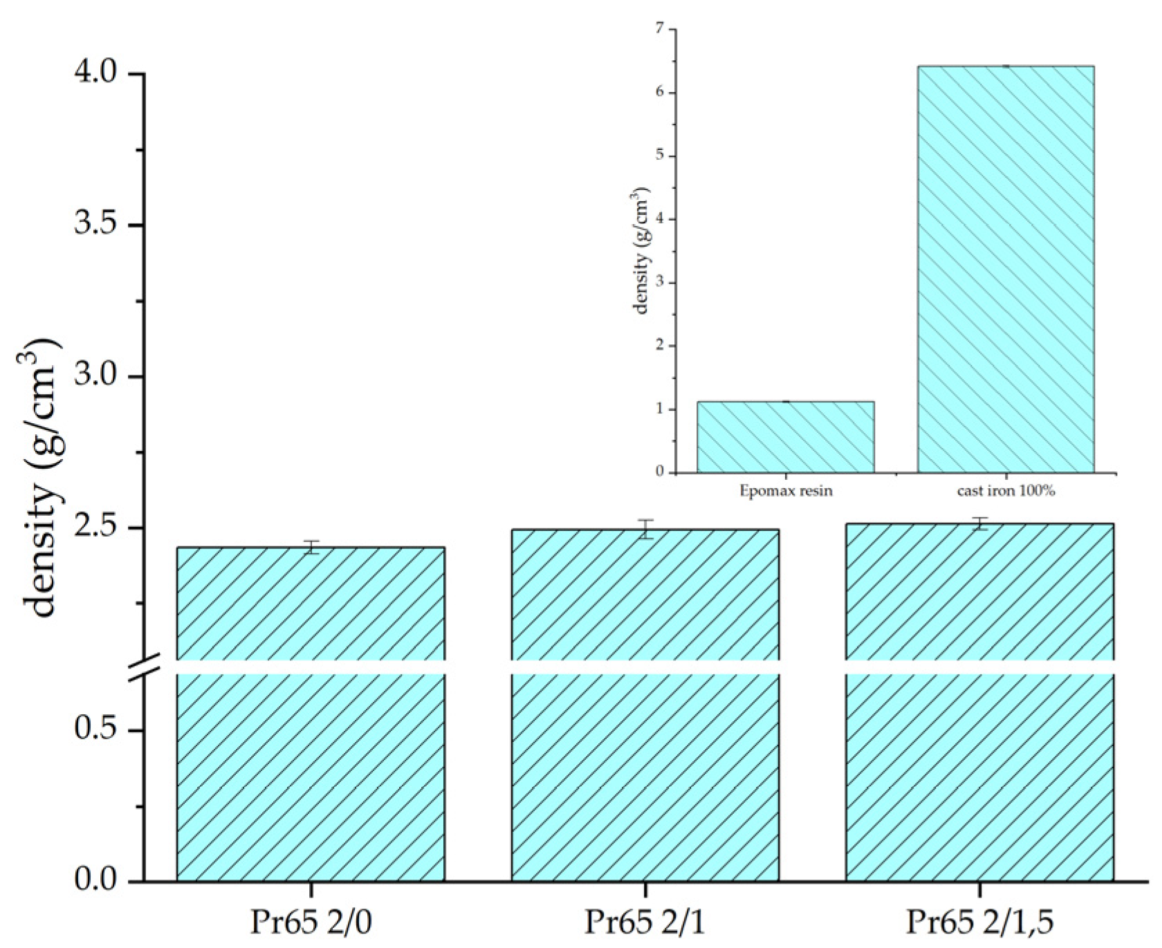
| Pr65 2/0 | 2.450 ± 0.013 | 2.3 |
| Pr65 2/1 | 2.488 ± 0.025 | 0.8 |
| Pr65 2/1.5 | 2.500 ± 0.015 | 0.3 |
| Sample | Maximum Strength | Tensile Strength | Young’s Modulus | Relative Elongation |
|---|---|---|---|---|
| N | MPa | GPa | % | |
| Pr65 2/0 | 646 ± 20 | 14.8 ± 0,8 | 2.76 ± 0.07 | 0.59 ± 0.01 |
| Pr65 2/1 | 882 ± 55 | 21.45 ± 1.45 | 3.82 ± 0.01 | 0.73 ± 0.06 |
| Pr65 2/1.5 | 1115 ± 10 | 28.35 ± 0.25 | 4.51 ± 0.03 | 0.98 ± 0.15 |
| Epoxy resin | 1280 ± 70 | 28.7 ± 0.5 | 1.81 ± 0.04 | 8.9 ± 0.6 |
| Sample | Maximum Strength | Compressive Strength | Young’s Modulus | Relative Elongation |
|---|---|---|---|---|
| N | MPa | GPa | % | |
| Pr65 2/0 | 4130 ± 7 | 39.6 ± 0.9 | 1.63 ± 0.07 | 4.62 ± 0.18 |
| Pr65 2/1 | 5380 ± 20 | 49.2 ± 1.2 | 1.95 ± 0.16 | 4.27 ± 0.17 |
| Pr65 2/1.5 | 5570 ± 15 | 53.8 ± 2.2 | 2.1 ± 0.1 | 5.00 ± 0.05 |
| Epoxy resin | 3480 ± 10 | 30.5 ± 1.1 | 0.77 ± 0.04 | 6.67 ± 0.17 |
| Sample | Maximum Strength | Flexural Strength | Young’s Modulus | Displacement |
|---|---|---|---|---|
| N | MPa | GPa | mm | |
| Pr65 2/0 | 76.3 ± 3.3 | 40.4 ± 0.2 | 3.32 ± 0.07 | 2.45 ± 0.18 |
| Pr65 2/1 | 89.5 ± 7.1 | 53.1 ± 1.4 | 4.78 ± 0.24 | 1.67 ± 0.05 |
| Pr65 2/1.5 | 92.9 ± 2.9 | 55.4 ± 1.0 | 5.02 ± 0.01 | 1.51 ± 0.13 |
| Epoxy resin | 92.5 ± 16.4 | 50.8 ± 1.4 | 1.86 ± 0.12 | 9.72 ± 0.84 |
| Samples | Corrosion Potential, Ecorr (mV) | Corrosion Current Density, icorr (mA·cm−2) | Anodic Tafel Coefficient, ba (mV) | Cathodic Tafel Coefficient, bc (mV) | Polarization Resistance, Rpol (Ω·cm2) | Corrosion Rate, CR (mm/year) |
|---|---|---|---|---|---|---|
| Pr65 2/0 | −557 | 19.05 | 1154 | 2637 | 18,317 | 0.242 |
| Pr65 2/1 | −562 | 18.21 | 914 | 399 | 6639 | 0.231 |
| Pr65 2/1.5 | −497 | 13.21 | 1074 | 641 | 13,215 | 0.168 |
| Cast iron 100% | −567 | 44.11 | 1014 | 340 | 2509 | 0.559 |
| Sample | Thermal Decomposition Temperature, °C | Area of Exothermic Peaks, J/g |
|---|---|---|
| Epoxy resin | 351.2 | 52.97 |
| Pr65 2/0 | 327.4 | 24.28 |
| Pr65 2/1 | 328.9 | 40.47 |
| Pr65 2/1.5 | 327.7 | 26.02 |
Disclaimer/Publisher’s Note: The statements, opinions and data contained in all publications are solely those of the individual author(s) and contributor(s) and not of MDPI and/or the editor(s). MDPI and/or the editor(s) disclaim responsibility for any injury to people or property resulting from any ideas, methods, instructions or products referred to in the content. |
© 2024 by the authors. Licensee MDPI, Basel, Switzerland. This article is an open access article distributed under the terms and conditions of the Creative Commons Attribution (CC BY) license (https://creativecommons.org/licenses/by/4.0/).
Share and Cite
Cieślak, R.; Figiel, P.; Kwiatkowski, K.; Dobrowolski, D.; Urbaniak, M.; Biedunkiewicz, A. Epoxy Composites with Post-Production Gray Cast-Iron Powders. Materials 2024, 17, 4333. https://doi.org/10.3390/ma17174333
Cieślak R, Figiel P, Kwiatkowski K, Dobrowolski D, Urbaniak M, Biedunkiewicz A. Epoxy Composites with Post-Production Gray Cast-Iron Powders. Materials. 2024; 17(17):4333. https://doi.org/10.3390/ma17174333
Chicago/Turabian StyleCieślak, Robert, Paweł Figiel, Konrad Kwiatkowski, Damian Dobrowolski, Magdalena Urbaniak, and Anna Biedunkiewicz. 2024. "Epoxy Composites with Post-Production Gray Cast-Iron Powders" Materials 17, no. 17: 4333. https://doi.org/10.3390/ma17174333
APA StyleCieślak, R., Figiel, P., Kwiatkowski, K., Dobrowolski, D., Urbaniak, M., & Biedunkiewicz, A. (2024). Epoxy Composites with Post-Production Gray Cast-Iron Powders. Materials, 17(17), 4333. https://doi.org/10.3390/ma17174333