Article

Influence of Ambient Relative Humidity on the Shrinkage Strain of Engineered Geopolymer Composites Based on Orthogonal Experimental Design

1
School of Civil Engineering, Zhengzhou University, Zhengzhou 450001, China
2
Zhengzhou Metro Group Co., Ltd., Zhengzhou 450001, China
*
Authors to whom correspondence should be addressed.
Materials 2024, 17(17), 4321; https://doi.org/10.3390/ma17174321
Submission received: 8 August 2024 / Revised: 24 August 2024 / Accepted: 27 August 2024 / Published: 30 August 2024

Abstract

With the aim to systematically analyze the ambient relative humidity on the shrinkage strain of Engineered Geopolymer Composites (EGCs), this paper studied four variables (fly ash to ground granulated blast furnace slag mass ratio, alkali content, water–binder ratio, and fiber volume content) though orthogonal experimental design and three different relative humidity values (30%, 60%, and 100% RH). The results indicated that, for EGC specimens under 30% RH and 60% RH, the decrease in slag content and increase in alkali content both resulted in greater drying shrinkage. The addition of fibers effectively reduced the shrinkage strain, while a minor impact on shrinkage was presented by the W/B ratio. The first and second key factors affecting the drying shrinkage strain were the FA/GGBS ratio and the alkali content. The optimal ratio of FA/GGBS, alkali content, and fiber volume fraction were 0/100, 4%, and 1.5%, respectively. Dring shrinkage strain was decreased with the increase in ambient relative humidity. Compared with the shrinkage strain under 30% RH, the reduction in shrinkage strain under 60% RH and 100%RH was up to 46.1% and 107.5%, respectively. At last, a relationship between shrinkage strain and curing age under 30% and 60% RH was established with a fitting degree from 0.9492 to 0.9987, while no clear relationship was presented under 100% RH. The results in this paper provide a practical method for solving the shrinkage problem of EGCs.

1. Introduction

As a novel green binder material, geopolymer is an inorganic binder prepared by activating aluminosilicate-rich raw materials, such as blast furnace slag and fly ash, with an alkali activator. Its reaction mechanism involves the cleavage of chemical bonds like -Si-O-Si-, -Si-O-Al-, and -Al-O-Al- within the raw materials in a highly alkaline environment, releasing active Si and Al monomers. These monomers undergo polymerization to form a three-dimensional network structure composed of SiO4 and AlO4 units linked by shared oxygen atoms.
This unique spatial structure enables geopolymer to exhibit the characteristics of high early/late strength, acid resistance, fire resistance, and so on [1,2]. Moreover, when compared with that of Ordinary Portland Cement (OPC), CO2 emissions during production of geopolymer binder materials can be reduced by approximately 50% to 80%, with the advantages of environmental friendliness and the ability to reuse solid waste. Despite its performance being comparable to or even superior to OPC, geopolymer inevitably shows a quasi-brittle characteristic similar to those of OPC. And its shrinkage property is of the greatest concern, reaching 2–3 times that of OPC [3].
Fiber composite technology is an effective method for enhancing material performance. By incorporating fibers into geopolymers, the ductility is significantly increased, resulting in a new type of fiber-reinforced composite material known as Engineered Geopolymer Composites (EGC). Up to now, the current research on EGC has mainly focused on mechanical and durability properties, while little research exists on shrinkage performance [4,5]. Evaluating shrinkage performance is crucial for assessing durability, as excessive shrinkage can lead to cracks in structures or components, allowing harmful agents from the environment to penetrate and adversely affect structural durability.
The factors influencing the shrinkage of geopolymers are numerous, including the type and dosage of mineral admixtures, the dosage of alkali activators, the water–cement ratio, and the curing conditions [6,7,8]. Studies have shown that an increase in slag content in fly ash–slag-based polymer concrete leads to increased autogenous shrinkage [9,10], while increasing fly ash content may result in a decrease in strength, but also a reduction in drying shrinkage [11,12]. However, other studies indicated that increasing slag content can reduce shrinkage strain [13,14]. For fly ash–slag-based geopolymer, a higher water–cement ratio leads to a reduction in drying shrinkage, but it has little effect on the drying shrinkage of slag-based geopolymer [15]. When sodium silicate is used as an alkali activator, reducing the modulus of water glass decreases drying shrinkage [16,17]. An increase in alkali dosage may result in greater shrinkage strain [11,18], although some studies indicated that when the alkali dosage exceeds a critical value, shrinkage decreases instead [19]. In addition, cement or geopolymer concrete curing relative humidity both have an important impact on the shrinkage performance, with higher humidity being very effective in alleviating early shrinkage development [7,20,21]. In the EGC system, the addition of fibers can effectively resist shrinkage stress, reduce stress concentration at crack tips, and restrict the development of shrinkage [22,23,24]. The incorporation of steel fiber can reduce the drying shrinkage of fly ash-based geopolymer by about 24% [22]. At a relative humidity of 100%, the maximum strain can be controlled within 1.5 mm/m by adding 0.2 wt % 3 mm or 6 mm long carbon fiber [23]. The addition of polypropylene fibers with volume fractions of 0.05%, 0.1%, 0.15%, and 0.2% can reduce the dry shrinkage strain of alkali-activated slag mortar by 10.3–26.2% [24]. These studies have effectively revealed and clarified the influence of various factors on the shrinkage properties of geopolymer. And the method was mainly focused on single-factor multi-level design. Given the complexity of the hydration reaction of geopolymer binder, many factors affecting experimental results need to be considered, which requires more effort and time to conduct a comprehensive analysis. The orthogonal experimental design method can effectively solve the above problem and analyze the main factors affecting the test results in multiple factors, which is conducive to optimizing the mix ratio design [25,26].
This article aims to systematically analyze the influence of four variables (fly ash to ground granulated blast furnace slag mass ratio, alkali content, water–binder ratio, and fiber volume content) though orthogonal experimental design and three different relative humidity values (30%, 60%, and 100% RH) on the shrinkage strain of Engineered Geopolymer Composites (EGCs). Additionally, it seeks to identify the key factors affecting shrinkage strain, determine the optimal mix ratio, and establish the relationship between shrinkage strain and curing age. The results in this paper would provide a practical method for solving the shrinkage problem of EGCs.

2. Experimental Program
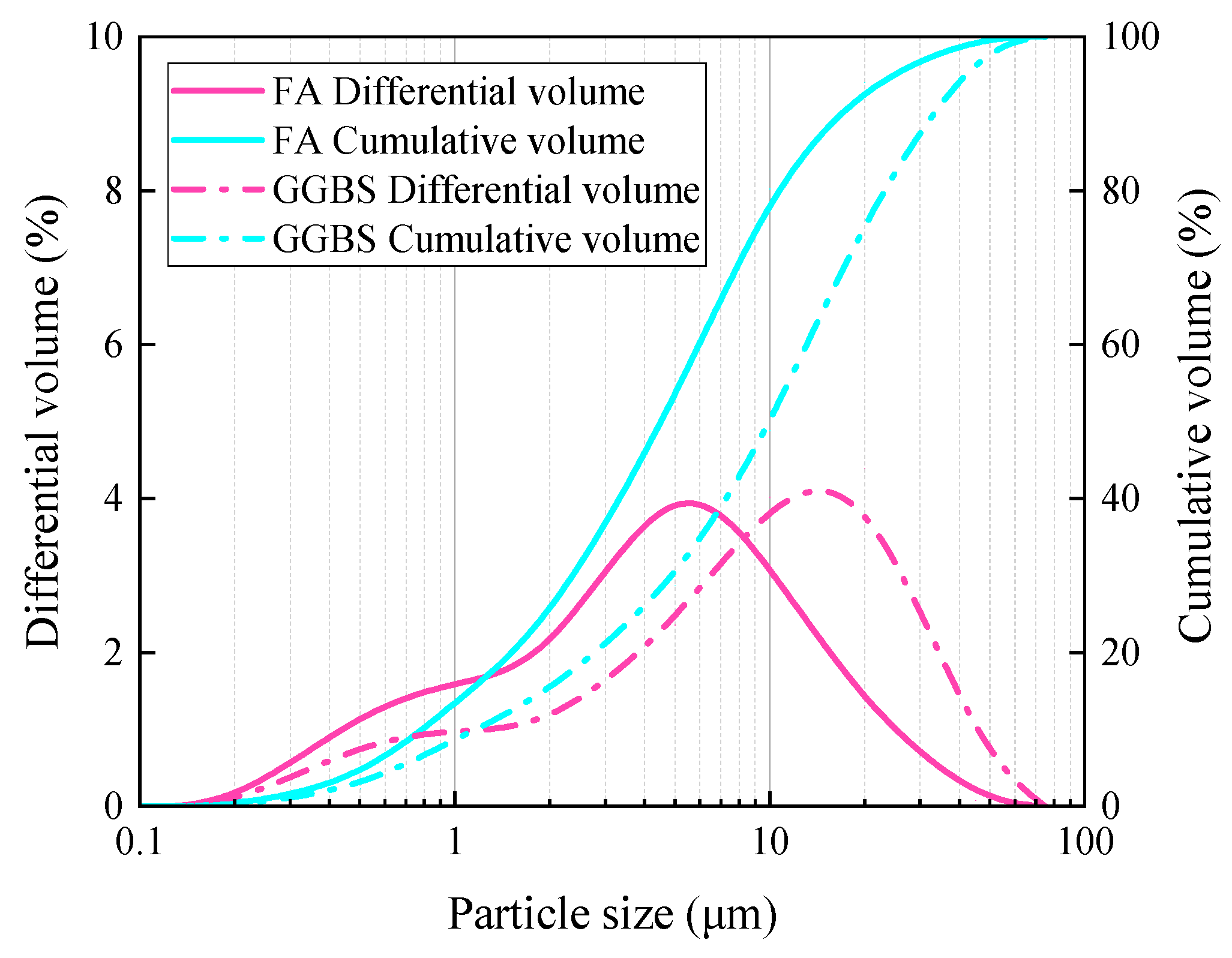
2.1. Raw Materials

Ground granulated blast furnace slag (GGBS) used in this experiment was classified as S95 grade and provided by Changwang Mining Products Co., Ltd. in Shijiazhuang, China. Grade I fly ash (FA) was provided by Yulian Power Plant in Gongyi, China. The chemical composition of FA and GGBS is shown in Table 1, and their particle size distribution is shown in Figure 1.
Alkali activator was prepared by dissolving industrial grade anhydrous sodium metasilicate (Na2SiO3), a white powder, provided by Henan Huiteng Chemical Technology Co., Ltd. (Luohe, China). Its technical specifications are shown in Table 2.
The PE fibers used in this experiment were produced by Zhejiang Quanmite New Material Technology Co., Ltd. in Jiaxing, China, and their technical specifications are shown in Table 3.

2.2. Design of Test Mix Proportion

Orthogonal experiments utilize independent variations and mutually orthogonal experimental matrices, allowing the level of each factor to vary independently. This method can comprehensively analyze the impact of multiple factors on the results in fewer experiments, saving time and resources. Regarding the mass ratio of fly ash to slag, some studies have shown that the incorporation of fly ash will have a favorable impact on inhibiting the shrinkage property of geopolymer cementitious materials [11]. And the higher the slag content, the lower the shrinkage strain [13]. In this experiment, four factors were focused on, namely, the mass ratio of fly ash to slag, the alkali content, the water–binder ratio, and the fiber volume fraction. Each factor was tested at 4 levels, using an L 16 ( 4 4 ) orthogonal table, as shown in Table 4. The range analysis method was used to determine the influence degree of each factor on the drying shrinkage performance of EGC, and the optimal mix proportion was established.
In addition, the compressive strength shown in Table 4, was tested using cubic specimens with dimensions of 50 mm × 50 mm × 50 mm. Its average value was calculated using three specimens.

2.3. Specimen Preparation and Curing

The FA, GGBS, and sodium metasilicate powder were weighed according to the specified proportions and sequentially added to the mixing drum. Initially, the mixture was stirred at low speed for 2 min. Then, the pre-weighed water was added, and the mixture was stirred at high speed for 2 min. Following this, the pre-measured PE fibers were added, and the mixture was stirred for an additional 3 min. The well-mixed mortar was quickly poured into the test mold and placed on a vibrating table for two rounds of vibration. The first round lasted for 45 s, during which the dispersion of fibers was observed. Once evenly vibrated, the surface of the test mold was smoothed with a trowel. After a 10 s interval, the second round of vibration started and lasted for 15 s to ensure uniform compaction of the materials. When casting the drying shrinkage specimen, nail heads must be packed densely on both sides of the test mold. The vibrated sample was wrapped in plastic wrap and then placed in an environment with a temperature of 20 °C ± 5 °C and a relative humidity (RH) of 50% ± 5% RH for 1 day before demolding.
After demolding, the specimens were placed in a sealed box for curing at a temperature of 20 °C ± 2 °C. Three different relative humidity levels—30%, 60%, and 100% RH—were set to explore their impact on the drying shrinkage of EGCs. The relative humidity was controlled by placing saturated salt solutions at the bottom of the box. Its principle is that at a constant temperature, the increase in salt in the solution will cause a decrease in saturated vapor pressure, resulting in a decrease in relative humidity. Therefore, 30%, 60%, and 100% RH are maintained by the saturated magnesium chloride solution, the saturated sodium bromide solution, and the poured water. The diagram illustrating the drying shrinkage specimen curing setup is shown in Figure 2.

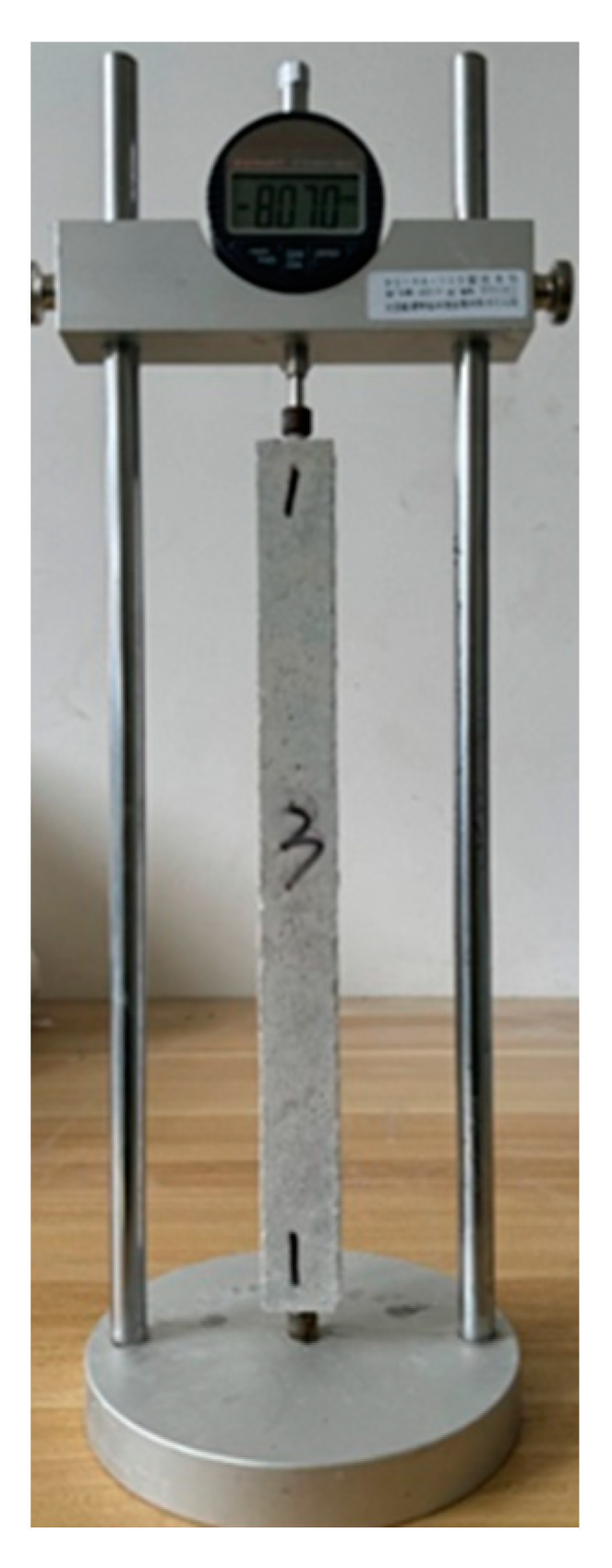
2.4. Drying Shrinkage Strain Test

The drying shrinkage test method followed the Chinese building materials industry standard “Test Method for Drying Shrinkage of Cement Mortar” (JC/T 603-2004) [27]. The length of the specimens was measured using the BC156-300 type comparative length gauge, produced by Beijing Hangjian Huaye Technology Development Co., Ltd. (as shown in Figure 3). This device consists of a digital dial indicator, a bracket, and a calibration rod. The digital dial indicator has an accuracy of 0.001 mm and a range of 12.7 mm.
The dimensions of the prismatic specimen for shrinkage strain tests were 25 mm × 25 mm × 280 mm, as shown in Figure 4. Each group consisted of three replicated specimens, whose preparation and curing process is presented in Section 2.3. After demolding, the length of the specimen was measured by an elongation comparator and recorded as the initial length, which was then recorded every 24 h.
The shrinkage strain was the average value of three identical specimens, and its calculation formula is shown in Equation (1):
ε t = L t L 0 L b
where:
L 0 —The initial length of the specimen, mm;
L t —The length of the specimen at time t, mm;
L b —The effective length of the tested specimen, taken as 250 mm;
ε t —The shrinkage strain value at time t, 10−6.

3. Results and Discussion

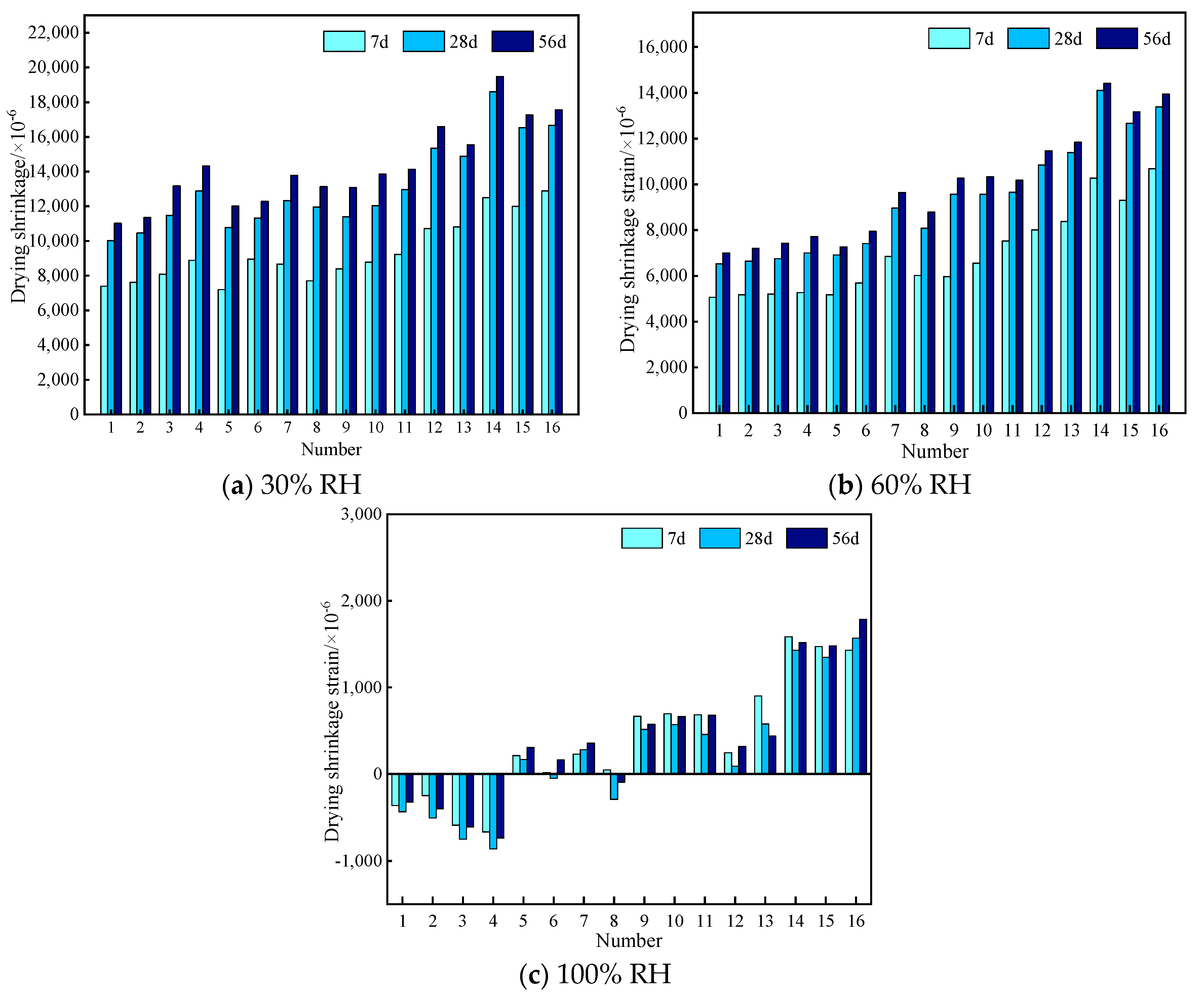
3.1. Drying Shrinkage Strain

The drying shrinkage strain of EGC specimens at 7 d, 28 d, and 56 d under 30%, 60%, and 100% RH are presented in Table 5, Table 6 and Table 7. Figure 5 shows the column chart of the dry shrinkage strain under different relative humidity levels and various ages. According to these shrinkage strain data, for specimens under 30% and 60% RH, a consistent pattern with increasing age was presented. And their shrinkage strain developed very fast at an early curing age, in which the shrinkage strain of all groups reached more than 55% of the final shrinkage value (the 56 d shrinkage strain was used as the final shrinkage value), and that of some groups reached more than 70%. Subsequently, the shrinkage rate gradually slowed down and stabilized by around 28 d. However, for specimens under 100% RH, the above phenomenon was not observed.

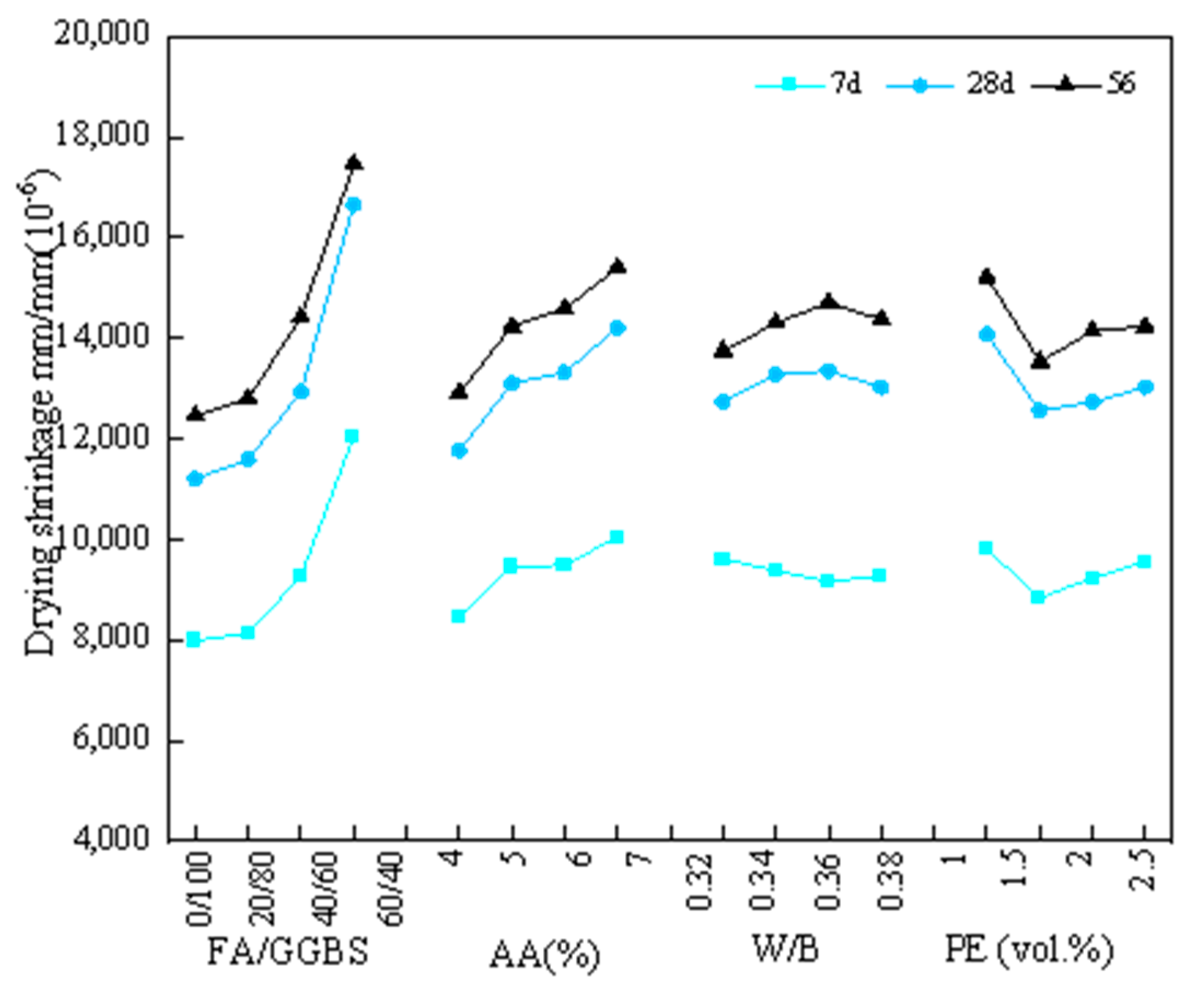
3.2. Analysis of Key Factors and Optimal Proportion for Drying Shrinkage

Due to the limitations of visual analysis to account for the impact of various factors, range analysis was performed, which is a statistical method used to evaluate the influence degree of various factors on results. This method quantifies the impact of each factor by comparing the ranges at different factor levels, with the goal of identifying which factors have a significant effect on performance. By calculating the range (denoted as R) for each factor, the relative importance of each factor was determined, in which the larger the R value, the greater the impact of the factor’s level changes on the experimental results. The formula for calculating the R value is shown in Equation (2).
R j = m a x K j 1 ¯ , K j 2 ¯ , , K j m ¯ m i n K j 1 ¯ , K j 2 ¯ , , K j m ¯
where K j m is the sum of the test indexes corresponding to the factor m level in column j, and K j m ¯ is the average value of K j m .
(1)
30% relative humidity
The results of the range analysis on the drying shrinkage strain of EGC specimens under 30% RH are shown in Table 8. Based on the magnitude of R values, it was observed that the R value of the FA/GGBS ratio was significantly larger than the other three factors, indicating its most significant impact on drying shrinkage, while an opposite phenomenon was observed on the R value of the W/B ratio. In a word, the order of factors influencing drying shrinkage at 7 d, 28 d, and 56 d, from strongest to weakest, was as follows: FA/GGBS ratio, alkali content, fiber volume content, and W/B ratio. The key factors were the FA/GGBS ratio and alkali content.
Figure 6 presents the relationship between the average drying shrinkage strain at different ages and various factors under 30% RH. Based on the average value Kavg, it was shown that the drying shrinkage strain at different ages increased with higher FA/GGBS ratio and alkali content. This phenomenon could be attributed to the following reasons: (1) Internal structural compactness and water loss rate, as for an FA/GGBS ratio of 0/100, a dense structure was formed by the higher reactivity and hydration degree of slag, and thus reduced the water loss rate, resulting in the lowest drying shrinkage strain shown in Figure 6. The opposite phenomenon was observed in the specimen with the highest FA content, such that for an FA/GGBS ratio of 40/60, a more loose structure was formed by the lower reactivity and hydration degree of fly ash, and thus increased the water loss rate [28], leading to the highest drying shrinkage strain shown in Figure 6. (2) High alkali content, as for an alkali content of 7%, the increase in alkali content effectively improved the alkalinity of the reaction environment, promoted the dissolution of aluminosilicate in slag and fly ash, and enhanced the dissolution rate of Si and Al [29]. A highly alkaline environment can destroy the aluminosilicate shell formed by the initial hydrolysis of the slag surface, promoting the hydration reaction [30] and improving the compactness of the hydration product structure. This results in an increase in the proportion of pores (2.5 nm–50 nm), leading to higher capillary pressure [31,32]. Furthermore, the high alkali content caused the pore solution to contain a large amount of Na+, Ca2+, Si4+, and Al3+ ions, increasing the surface tension of the pore solution [33]. The rapid reduction in these liquid ions will generate large shrinkage stress within the matrix [34,35].
In addition, as for the fiber volume fraction, as shown in Figure 6, the average value Kavg at different ages was initially decreased and then increased from 1.0% to 2.5%, presenting an optimal fiber volume content of 1.5%. The reduction in drying shrinkage strain was mainly due to the uniform and disoriented distribution of fibers in the matrix [36]. This not only improved the tensile properties of the matrix itself, but also limited the contraction stress of EGCs due to the interfacial bonding force between the fiber and the matrix [37]. As for the W/B ratio, two trends were present at different ages, and drying shrinkage strain within a narrow range from 0.32 to 0.38 was observed.
Based on the range analysis in Table 8 and Figure 6, the key factors were determined to be the FA/GGBS ratio and alkali content, which was consistent with the existing research [10,11,13,18,32]. The change in these two factors will have a greater impact on drying shrinkage. As for the EGC specimens under 30% RH, according to the minimum shrinkage strain, the optimal FA/GGBS ratio, alkali content, W/B ratio, and fiber volume fraction were determined to be 0/100, 4%, 0.32, and 1.5%, respectively. This corresponded to the A1B1C1D2 group.
(2)
60% relative humidity
The results of the range analysis on the drying shrinkage strain of EGC specimens under 60% RH are presented in Table 9. According to the magnitude of R values, a similar trend to that of EGC specimens under 30% RH was present. And the order of factors influencing drying shrinkage at 7 d, 28 d, and 56 d, from strongest to weakest, was as follows: FA/GGBS ratio, alkali content, fiber volume content, and W/B ratio.
Figure 7 depicts the relationship between the average drying shrinkage strain at different ages and various factors under 60% RH. Based on the average value Kavg, it was observed that similar trends about the drying shrinkage strain at different ages were presented, which was consistent with those observed at 30% RH, while there was still a difference in the trend in the W/B ratio, presenting the minimum shrinkage strain at 0.38.
Based on the range analysis in Table 9 and Figure 7, the key factors were determined to be the FA/GGBS ratio and alkali content. As for the EGC specimens under 60% RH, according to the minimum shrinkage strain, the optimal FA/GGBS ratio, alkali content, W/B ratio, and fiber volume fraction were determined to be 0/100, 4%, 0.38, and 1.5%, respectively. This corresponded to the A1B1C4D2 group.
(3)
100% relative humidity
The results of the range analysis on the shrinkage strain of EGC specimens under 100% RH are presented in Table 10. According to the magnitude of R values, the key factor influencing the shrinkage strain of EGC specimens at 7 d, 28 d, and 56 d was the FA/GGBS ratio. And the other three factors had less influence. Figure 8 depicts the relationship between the average shrinkage strain at different ages and various factors under 100% RH. Based on the average value Kavg, it was observed that the shrinkage strain at different ages increased with a higher FA/GGBS ratio, while an opposite phenomenon was observed on the Kavg value of the W/B ratio. Additionally, for an FA/GGBS ratio of 0/100, expansive behavior occurred in the EGC specimens. In a word, lower shrinkage strain was observed compared to those of the EGC specimens under 30% and 60% RH.
Based on the range analysis in Table 10 and Figure 8, the key factor was determined to be the FA/GGBS ratio. As for the EGC specimens under 100% RH, according to the minimum shrinkage strain, the optimal FA/GGBS ratio, alkali content, W/B ratio, and fiber volume fraction were determined to be 20/80, 7%, 0.38, and 1.5%, respectively. This corresponded to the A2B4C4D2 group.

3.3. Effect of Ambient Curing Humidity on Shrinkage Strain

Figure 9 shows the shrinkage strain of each group at different ages under various ambient curing humidity values. It was clearly found that the shrinkage strain increased with the decrease in ambient curing humidity at all curing ages, presenting the highest shrinkage value under 30% RH and the lowest shrinkage value under 100% RH. Additionally, some data were below zero when EGC specimens were under 100% RH, indicating that expansive behavior occurred. To some extent, increasing ambient curing humidity was an effective method to reduce the shrinkage and shrinkage cracking. This phenomenon was mainly due to the high internal relative humidity, resulting in the reduction in capillary pore negative pressure [38,39].
Combined with the shrinkage data in Table 5, Table 6 and Table 7, the shrinkage strain reduction percentages of EGC specimens at 7 d, 28 d, and 56 d are shown in Table 11, Table 12, and Table 13, respectively. From Table 11, compared to the shrinkage strain under 30% RH at 7 d, the shrinkage strain values under 60% RH and 100% RH were reduced by 18.4%~40.7% and 88.9%~107.5%, respectively. From Table 12 and Table 13, for EGC specimens under 100% RH, the reduction percentage of shrinkage strain was close to that of specimens under 30% RH. And this reduction percentage was higher at 28 d and 56 d, presenting the highest values of about 45.1% and 46.1%, respectively.

3.4. Relationship between Shrinkage Strain and Curing Age

Shrinkage strain–curing age fitting curves of EGC specimens under 30% RH and 60% RH are shown in Figure 10 and Figure 11, respectively. Regression analysis was conducted based on the measured data, and a mathematical model was fitted to predict the shrinkage strain. According to the concrete drying shrinkage prediction model summarized in prior research [40], it was found that the proposed hyperbolic function could effectively fit the relationship between shrinkage strain and curing age, with the fitting equation shown in Equation (3).
ε t = t × 10 6 a + b × t
where ε(t) represents the dry shrinkage strain of EGC at time t, and a and b are parameters related to the binder components. The parameters for each group’s fitting curve equation are listed in Table 14 and Table 15. From the data in these tables, it can be observed that under 30% RH, the fitting degree was from 0.9642 to 0.9987, while it was from 0.9492 to 0.9966 under 60% RH. It should be noted that there was no clear relationship between shrinkage strain and curing age, due to the appearance of expansive and shrinkage behavior.

4. Conclusions

This paper primarily investigated the drying shrinkage strain of EGC specimens under three different ambient curing relative humidity values. Sixteen specimens were prepared and tested through orthogonal experimental design and orthogonal experimental analysis methods. Four variables, namely, the FA/GGBS ratio, alkali content, W/B ratio, and fiber volume content, were analyzed. The variation law, key influencing factors, and the optimal mix design of EGC drying shrinkage strain under 30%, 60%, and 100% RH were obtained. And fitting equations between the shrinkage strain and curing age were established. The main conclusions could be summarized as follows:
(1)
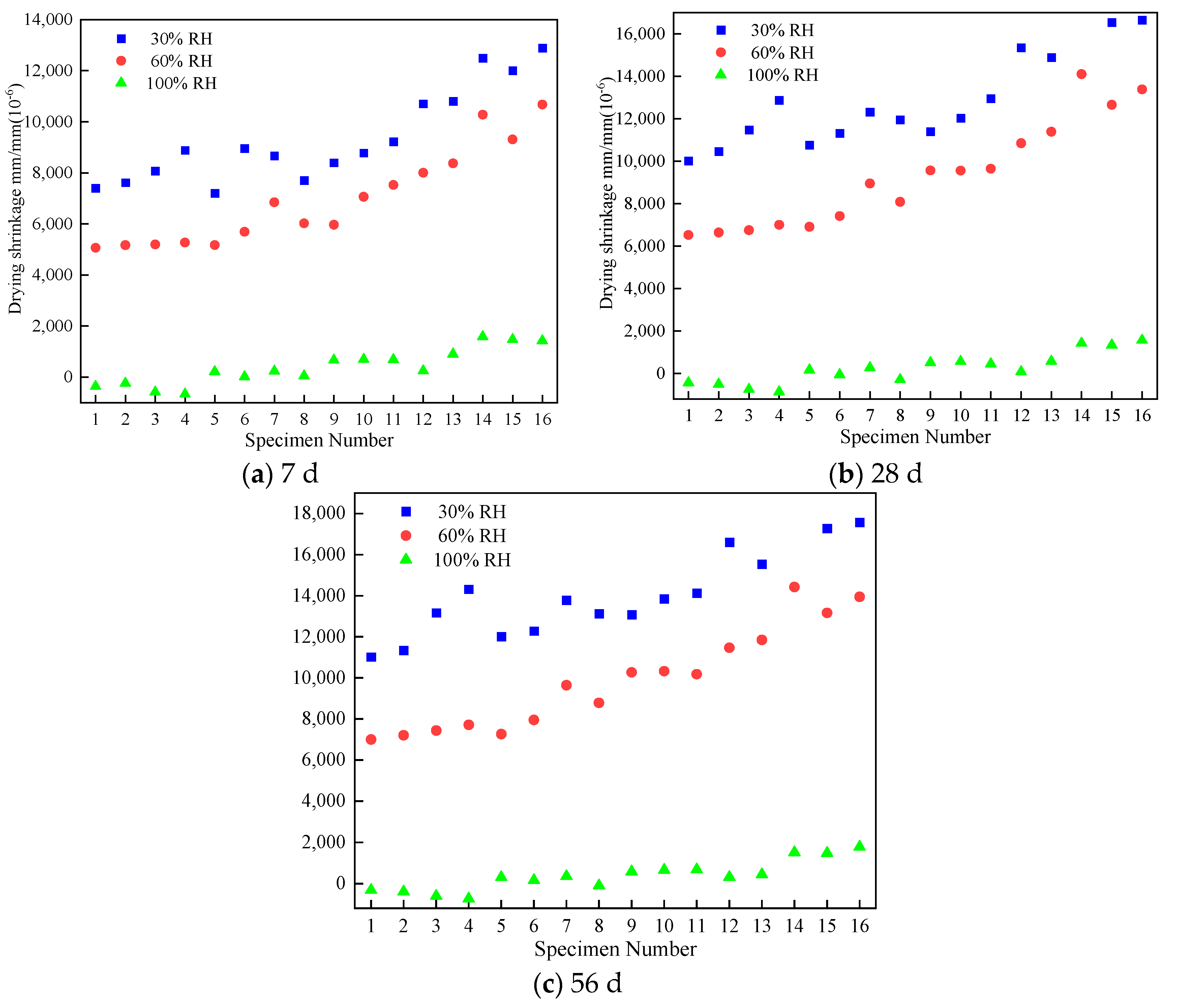
The drying shrinkage strain was decreased with the increase in ambient relative humidity. For specimens under 30% and 60% RH, the shrinkage strain developed rapidly at 7 d, with more than 55% of 56 d shrinkage strain.
(2)
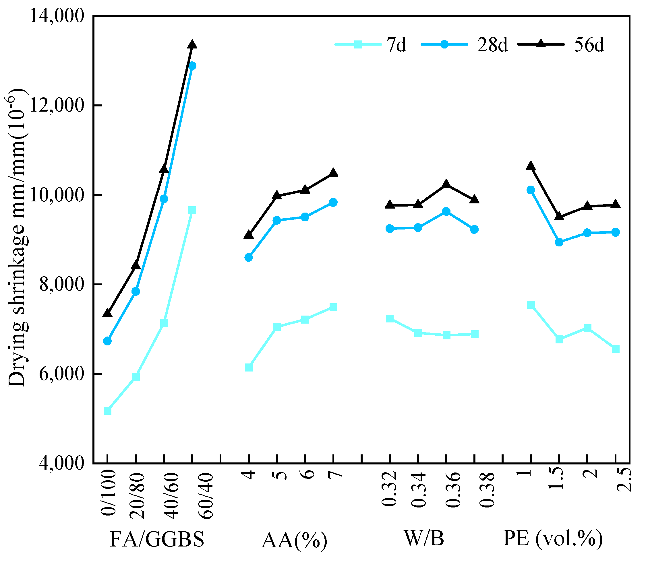
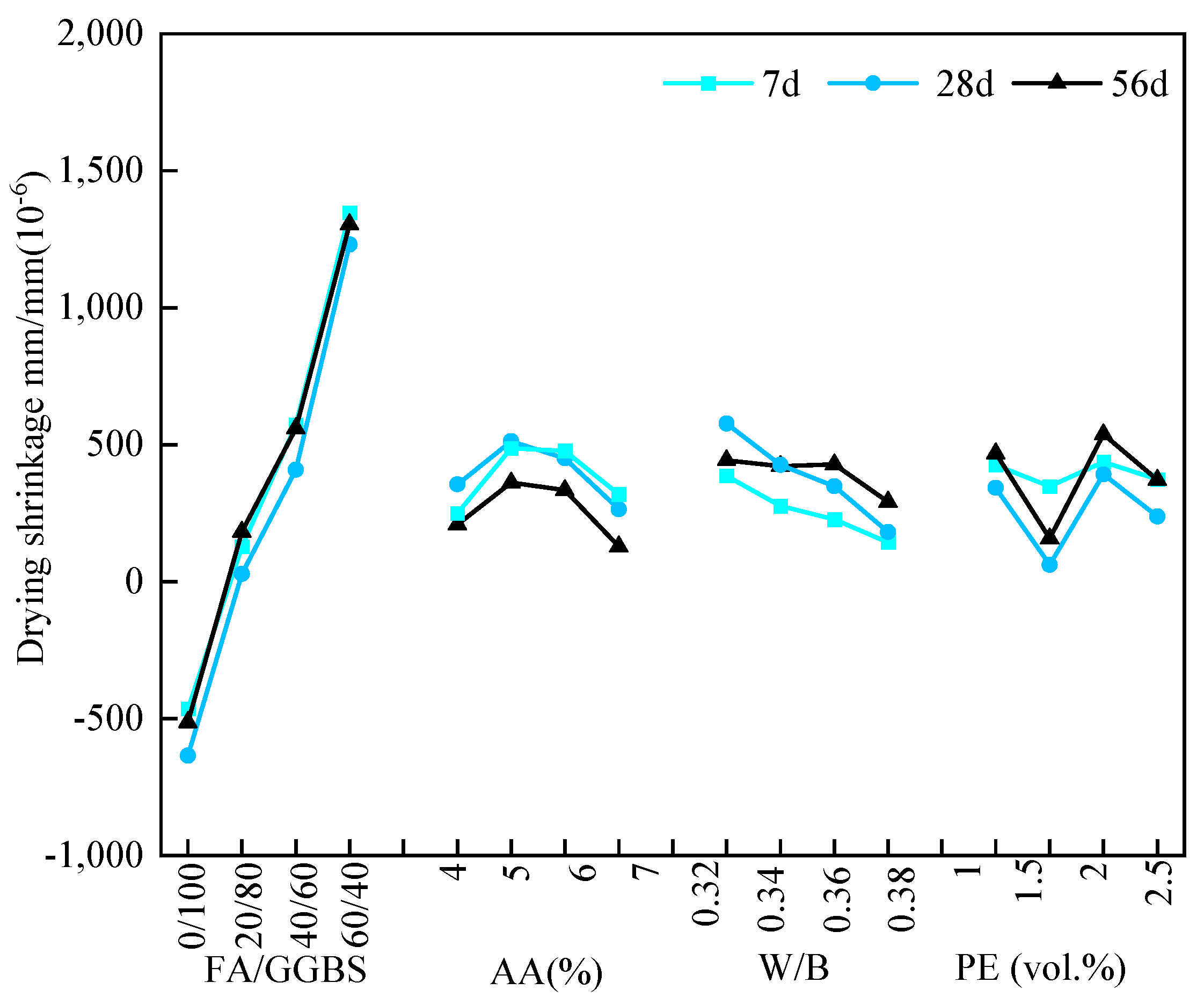
According to the range analysis, for specimens under 30% and 60% RH, the key factors affecting the drying shrinkage strain of EGC specimens under 30% and 60% RH were the FA/GGBS ratio and the alkali content. The optimal mix ratio was A1B1CxD2, with the FA/GGBS ratio, alkali content, and fiber volume fraction being 0/100, 4%, and 1.5%, respectively.
(3)
For specimens under 30% and 60% RH, the decrease in slag content and increase in alkali content both resulted in greater drying shrinkage. The addition of fibers effectively reduced the shrinkage strain, while a minor impact on shrinkage was observed for the W/B ratio.
(4)
Compared with the shrinkage strain under 30% RH, the reduction percentages of shrinkage strain under 60% and 100%RH were up to 46.1% and 107.5%, respectively.
(5)
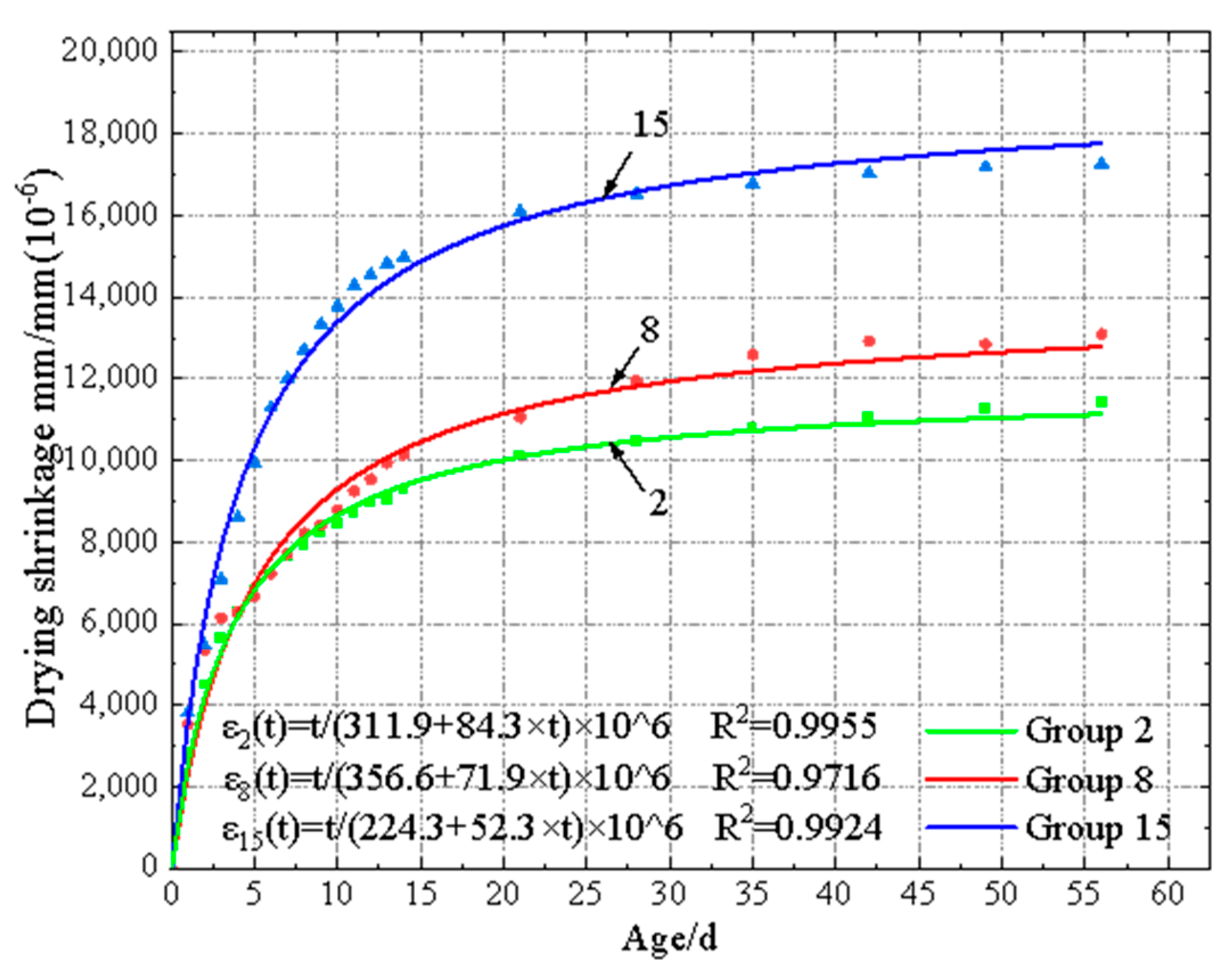
A relationship between shrinkage strain and curing age under 30% and 60% RH was established with a fitting degree from 0.9492 to 0.9987. No clear relationship was observed under 100% RH due to the appearance of expansive and shrinkage behavior.
This study points out that the increase in ambient relative humidity can significantly reduce the contraction strain of EGCs. A high humidity environment should be maintained during its early curing phase to ensure the good application of EGCs in engineering. In addition, the effect of ambient relative humidity on the shrinkage mechanism of EGCs should be further studied in future work.

Author Contributions

Conceptualization, Z.Y.; writing—original draft preparation, H.W.; formal analysis, H.W.; data curation, Y.Z.; writing—review and editing, Z.Y. and Y.Z.; project administration, Z.Y.; funding acquisition, Z.Y. All authors have read and agreed to the published version of the manuscript.

Funding

This research was funded by the Key Research and Development Project of Henan Province (Grant No. 231111321000) and the Key Scientific Research Project of Colleges and Universities in Henan Province (Grant No.24A560022).

Data Availability Statement

The raw data supporting the conclusions of this article will be made available by the authors on request.

Acknowledgments

The authors are grateful to the Key Research and Development Project of Henan Province (Grant No. 231111321000) and the Key Scientific Research Project of Colleges and Universities in Henan Province (Grant No.24A560022) is gratefully acknowledged.

Conflicts of Interest

Author Hongyin Wang was employed by the Zhengzhou Metro Group Co., Ltd. The remaining authors declare that the research was conducted in the absence of any commercial or financial relationships that could be construed as a potential conflict of interest.

References

  1. Wang, S.; Xue, Q.; Zhu, Y.; Li, G.; Wu, Z.; Zhao, K. Experimental study on material ratio and strength performance of geopolymer-improved soil. Constr. Build. Mater. 2021, 267, 120469. [Google Scholar] [CrossRef]
  2. Türkmen, İ.; Karakoç, M.B.; Kantarcı, F.; Maraş, M.M.; Demirboğa, R. Fire resistance of geopolymer concrete produced from Elazığ ferrochrome slag. Fire Mater. 2016, 40, 836–847. [Google Scholar] [CrossRef]
  3. Bakharev, T.; Sanjayan, J.; Cheng, Y.-B. Resistance of alkali-activated slag concrete to acid attack. Cem. Concr. Res. 2003, 33, 1607–1611. [Google Scholar] [CrossRef]
  4. Kan, L.; Gan, Y.; Dai, W.; Lv, L.; Dai, L.; Zhai, J.; Wang, F. Curing-dependent behaviors of sustainable alkali-activated fiber reinforced composite: Temperature and humidity effects. J. Build. Eng. 2024, 96, 110392. [Google Scholar] [CrossRef]
  5. MValente, M.; Sambucci, M.; Sibai, A.; Iannone, A. Novel cement-based sandwich composites engineered with ground waste tire rubber: Design, production, and preliminary results. Mater. Today Sustain. 2022, 20, 100247. [Google Scholar]
  6. Yang, T.; Zhu, H.; Zhang, Z. Influence of fly ash on the pore structure and shrinkage characteristics of metakaolin-based geopolymer pastes and mortars. Constr. Build. Mater. 2017, 153, 284–293. [Google Scholar] [CrossRef]
  7. Chi, M. Effects of dosage of alkali-activated solution and curing conditions on the properties and durability of alkali-activated slag concrete. Constr. Build. Mater. 2012, 35, 240–245. [Google Scholar] [CrossRef]
  8. Amran, M.; Debbarma, S.; Ozbakkaloglu, T. Fly ash-based eco-friendly geopolymer concrete: A critical review of the long-term durability properties. Constr. Build. Mater. 2021, 270, 121857. [Google Scholar] [CrossRef]
  9. Hojati, M.; Radlińska, A. Shrinkage and strength development of alkali-activated fly ash-slag binary cements. Constr. Build. Mater. 2017, 150, 808–816. [Google Scholar] [CrossRef]
  10. Lee, N.K.; Jang, J.G.; Lee, H.K. Shrinkage characteristics of alkali-activated fly ash/slag paste and mortar at early ages. Cem. Concr. Compos. 2014, 53, 239–248. [Google Scholar] [CrossRef]
  11. Chi, M.; Huang, R. Binding mechanism and properties of alkali-activated fly ash/slag mortars. Constr. Build. Mater. 2013, 40, 291–298. [Google Scholar] [CrossRef]
  12. Gao, X.; Yu, Q.L.; Brouwers, H.J.H. Assessing the porosity and shrinkage of alkali activated slag-fly ash composites designed applying a packing model. Constr. Build. Mater. 2016, 119, 175–184. [Google Scholar] [CrossRef]
  13. Hardjito, D.; Wallah, S.E.; Sumajouw, D.M.; Rangan, B.V. On the Development of Fly Ash-Based Geopolymer Concrete. Mater. J. 2004, 101, 467–472. [Google Scholar]
  14. Yao, X.; Yang, T.; Zhang, Z. Compressive strength development and shrinkage of alkali-activated fly ash–slag blends associated with efflorescence. Mater. Struct. 2016, 49, 2907–2918. [Google Scholar] [CrossRef]
  15. Zhu, X.; Tang, D.; Yang, K.; Zhang, Z.; Li, Q.; Pan, Q.; Yang, C. Effect of Ca(OH)2 on shrinkage characteristics and microstructures of alkali-activated slag concrete. Constr. Build. Mater. 2018, 175, 467–482. [Google Scholar] [CrossRef]
  16. Un, C.H.; Sanjayan, J.G.; Nicolas, R.S.; Van Deventer, J.S.J. Predictions of long-term deflection of geopolymer concrete beams. Constr. Build. Mater. 2015, 94, 10–19. [Google Scholar] [CrossRef]
  17. Mastali, M.; Kinnunen, P.; Dalvand, A.; Firouz, R.M.; Illikainen, M. Drying shrinkage in alkali-activated binders—A critical review. Constr. Build. Mater. 2018, 190, 533–550. [Google Scholar] [CrossRef]
  18. Atiş, C.D.; Bilim, C.; Çelik, Ö.; Karahan, O. Effects of nano-TiO2 on strength, shrinkage and microstructure of alkali activated slag pastes. Constr. Build. Mater. 2009, 23, 548–555. [Google Scholar]
  19. Taghvayi, H.; Behfarnia, K.; Khalili, M. The Effect of Alkali Concentration and Sodium Silicate Modulus on the Properties of Alkali-Activated Slag Concrete. ACT 2018, 16, 293–305. [Google Scholar] [CrossRef]
  20. Liu, C.; Wu, H.; Li, Z.; Shi, H.; Ye, G. Effect of curing condition on mechanical properties and durability of alkali-activated slag mortar. Constr. Build. Mater. 2024, 439, 137376. [Google Scholar] [CrossRef]
  21. Hasnaoui, A.; Ghorbel, E.; Wardeh, G. Effect of Curing Conditions on the Performance of Geopolymer Concrete Based on Granulated Blast Furnace Slag and Metakaolin. J. Mater. Civ. Eng. 2021, 33, 04020501. [Google Scholar] [CrossRef]
  22. Baradaran, S.; Moghaddam, E.; Basirun, W.J.; Mehrali, M.; Sookhakian, M.; Hamdi, M.; Moghaddam, M.R.N.; Alias, Y. Mechanical properties and biomedical applications of a nanotube hydroxyapatite-reduced graphene oxide composite. Carbon 2014, 69, 32–45. [Google Scholar] [CrossRef]
  23. Vilaplana, J.L.; Baeza, F.J.; Galao, O.; Alcocel, E.G.; Zornoza, E.; Garcés, P. Mechanical properties of alkali activated blast furnace slag pastes reinforced with carbon fibers. Constr. Build. Mater. 2016, 116, 63–71. [Google Scholar] [CrossRef]
  24. Xu, Y.; Chen, H.; Wang, P. Effect of Polypropylene Fiber on Properties of Alkali-Activated Slag Mortar. Adv. Civ. Eng. 2020, 2020, 4752841. [Google Scholar] [CrossRef]
  25. Luévano-Hipólito, E.; Torres-Martínez, L.M.; Rodríguez-González, E. Recycling Waste Materials to Fabricate Solar-Driven Self-Cleaning Geopolymers. Waste Biomass Valor. 2024, 15, 2833–2843. [Google Scholar] [CrossRef]
  26. Karthik, S.; Mohan, K.S.R. A Taguchi Approach for Optimizing Design Mixture of Geopolymer Concrete Incorporating Fly Ash, Ground Granulated Blast Furnace Slag and Silica Fume. Crystals 2021, 11, 1279. [Google Scholar] [CrossRef]
  27. JC/T 603-2004; Standard Test Method for Drying Shinkage of Mortar. (In Chinese). Available online: http://www.njbz365.com/znzb/page/standard-detail-information.html?value=JC/T%20603-2004&Type=2 (accessed on 7 August 2024).
  28. Brough, A.R.; Atkinson, A. Sodium silicate-based, alkali-activated slag mortars. Cem. Concr. Res. 2002, 32, 865–879. [Google Scholar] [CrossRef]
  29. Chindaprasirt, P.; Jaturapitakkul, C.; Chalee, W.; Rattanasak, U. Comparative study on the characteristics of fly ash and bottom ash geopolymers. Waste Manag. 2009, 29, 539–543. [Google Scholar] [CrossRef]
  30. Jiang, D.; Shi, C.; Zhang, Z. Recent progress in understanding setting and hardening of alkali-activated slag (AAS) materials. Cem. Concr. Compos. 2022, 134, 104795. [Google Scholar] [CrossRef]
  31. Yang, J.; Wang, Q.; Zhou, Y. Influence of Curing Time on the Drying Shrinkage of Concretes with Different Binders and Water-to-Binder Ratios. Adv. Mater. Sci. Eng. 2017, 2017, 2695435. [Google Scholar] [CrossRef]
  32. Collins, F.; Sanjayan, J.G. Effect of pore size distribution on drying shrinking of alkali-activated slag concrete. Cem. Concr. Res. 2000, 30, 1401–1406. [Google Scholar] [CrossRef]
  33. Kumarappa, D.B.; Peethamparan, S.; Ngami, M. Autogenous shrinkage of alkali activated slag mortars: Basic mechanisms and mitigation methods. Cem. Concr. Res. 2018, 109, 1–9. [Google Scholar] [CrossRef]
  34. Neto, A.A.M.; Cincotto, M.A.; Repette, W. Mechanical properties, drying and autogenous shrinkage of blast furnace slag activated with hydrated lime and gypsum. Cem. Concr. Compos. 2010, 32, 312–318. [Google Scholar] [CrossRef]
  35. Neto, A.A.M.; Cincotto, M.A.; Repette, W. Drying and autogenous shrinkage of pastes and mortars with activated slag cement. Cem. Concr. Res. 2008, 38, 565–574. [Google Scholar] [CrossRef]
  36. Cao, Y.; Fan, Q.; Azar, S.M.; Alyousef, R.; Yousif, S.T.; Wakil, K.; Jermsittiparsert, K.; Ho, L.S.; Alabduljabbar, H.; Alaskar, A. Computational parameter identification of strongest influence on the shear resistance of reinforced concrete beams by fiber reinforcement polymer. Structures 2020, 27, 118–127. [Google Scholar] [CrossRef]
  37. Rashad, A.M. The effect of polypropylene, polyvinyl-alcohol, carbon and glass fibres on geopolymers properties. Mater. Sci. Technol. 2019, 35, 127–146. [Google Scholar] [CrossRef]
  38. Lura, P.; Jensen, O.M.; Van Breugel, K. Autogenous shrinkage in high-performance cement paste: An evaluation of basic mechanisms. Cem. Concr. Res. 2003, 33, 223–232. [Google Scholar] [CrossRef]
  39. Ma, Y.; Ye, G. The shrinkage of alkali activated fly ash. Cem. Concr. Res. 2015, 68, 75–82. [Google Scholar] [CrossRef]
  40. Study on Prediction Model of Concrete Strength and Drying Shrinkage; China Academy of Building Research: Beijing, China, 2008. (In Chinese)
Figure 1. Particle size distribution of FA and GGBS.
Materials 17 04321 g001
Figure 2. Diagram illustrating the drying shrinkage specimen curing setup.
Materials 17 04321 g002
Figure 3. BC156-300 type comparative length gauge.
Materials 17 04321 g003
Figure 4. Drying shrinkage specimen: (a) schematic diagram, (b) test specimen.
Materials 17 04321 g004
Figure 5. Column chart of the dry shrinkage strain under different relative humidity levels and various ages.
Materials 17 04321 g005
Figure 6. Relationship between the average drying shrinkage strain at different ages and various factors under 30% RH.
Materials 17 04321 g006
Figure 7. Relationship between the average drying shrinkage strain at different ages and various factors under 60% RH.
Materials 17 04321 g007
Figure 8. Relationship between the average shrinkage strain at different ages and various factors under 100% RH.
Materials 17 04321 g008
Figure 9. Shrinkage strain of each group at different ages under various ambient curing humidity values.
Materials 17 04321 g009
Figure 10. Shrinkage strain–curing age fitting curves of EGC specimens under 30% RH.
Materials 17 04321 g010
Figure 11. Shrinkage strain–curing age fitting curves of EGC specimens under 60% RH.
Materials 17 04321 g011
Table 1. Chemical composition of FA and GGBS.
CompositionSiO2Al2O3Fe2O3CaOMgONa2O
FA (%)53.9731.154.164.011.010.89
GGBS (%)32.1517.000.435.349.950.59
Table 2. Technical specifications of anhydrous sodium metasilicate.
Na2O ContentSiO2 ContentParticle SizeDensityInsoluble in Water
50.63%46.27%99.49 mesh1.23 g/cm30.007%
Table 3. Technical specifications of PE fibers.
Diameter (μm)Density (g/cm3)Length (mm)Tensile Strength (MPa)Elastic Modulus (GPa)Break Elongation (%)
19–430.981230001102–3
Table 4. Orthogonal table for EGC experiments.
Number FA/GGBS
Ratio
Alkali
Content
(%)
W/B RatioFiber Content (vol.%)Compressive Strength
(MPa)
1 A 1 B 1 C 1 D 1 0/1004%0.321.0%78.6 ± 2.3
2 A 1 B 2 C 2 D 2 0/1005%0.341.5%77.5 ± 2.5
3 A 1 B 3 C 3 D 3 0/1006%0.362.0%75.0 ± 3.1
4 A 1 B 4 C 4 D 4 0/1007%0.382.5%75.7 ± 2.7
5 A 2 B 1 C 2 D 3 20/804%0.342.0%67.3 ± 4.5
6 A 2 B 2 C 1 D 4 20/805%0.322.5%82.3 ± 3.2
7 A 2 B 3 C 4 D 1 20/806%0.381.0%71.8 ± 2.2
8 A 2 B 4 C 3 D 2 20/807%0.361.5%68.7 ± 2.4
9 A 3 B 1 C 3 D 4 40/604%0.362.5%53.5 ± 2.5
10 A 3 B 2 C 4 D 3 40/605%0.382.0%59.8 ± 3.8
11 A 3 B 3 C 1 D 2 40/606%0.321.5%66.4 ± 1.8
12 A 3 B 4 C 2 D 1 40/607%0.341.0%81.7 ± 4.1
13 A 4 B 1 C 4 D 2 60/404%0.381.5%42.8 ± 2.1
14 A 4 B 2 C 3 D 1 60/405%0.361.0%62.8 ± 3.2
15 A 4 B 3 C 2 D 4 60/406%0.342.5%60.0 ± 2.7
16 A 4 B 4 C 1 D 3 60/407%0.322.0%65.3 ± 2.3
Table 5. Dry shrinkage strain of EGC specimens at 7 d, 28 d, and 56 d under 30% RH.
Specimen
Number
Drying Shrinkage Strain (10−6)
7 d28 d56 d
1A1B1C1D1739810,02111,017
2A1B2C2D2762010,46211,342
3A1B3C3D3807611,47613,167
4A1B4C4D4888612,87614,320
5A2B1C2D3720010,76812,007
6A2B2C1D4895111,31912,281
7A2B3C4D1866312,32413,784
8A2B4C3D2770511,94613,131
9A3B1C3D4839511,39713,076
10A3B2C4D3877812,03513,856
11A3B3C1D2922412,95414,128
12A3B4C2D110,70715,34916,595
13A4B1C4D210,80214,88215,539
14A4B2C3D112,49218,60019,472
15A4B3C2D412,00216,53617,266
16A4B4C1D312,88916,65617,563
Table 6. Dry shrinkage strain of EGC specimens at 7 d, 28 d, and 56 d under 60% RH.
Specimen
Number
Drying Shrinkage Strain (10−6)
7 d28 d56 d
1A1B1C1D1506765296998
2A1B2C2D2517066467202
3A1B3C3D3520067567435
4A1B4C4D4527270087716
5A2B1C2D3517269167263
6A2B2C1D4569274167948
7A2B3C4D1685189569639
8A2B4C3D2602280888785
9A3B1C3D45969956910,268
10A3B2C4D37063956010,327
11A3B3C1D27524965110,180
12A3B4C2D1800510,85111,465
13A4B1C4D2837611,39211,848
14A4B2C3D110,27614,10314,419
15A4B3C2D4930712,65913,164
16A4B4C1D310,67713,38413,944
Table 7. Dry shrinkage strain of EGC specimens at 7 d, 28 d, and 56 d under 100% RH.
Specimen
Number
Drying Shrinkage Strain (10−6)
7 d28 d56 d
1A1B1C1D1−361−432−319
2A1B2C2D2−245−503−396
3A1B3C3D3−588−748−607
4A1B4C4D4−664−860−735
5A2B1C2D3213169304
6A2B2C1D416−51163
7A2B3C4D1230280356
8A2B4C3D247−288−95
9A3B1C3D4667516576
10A3B2C4D3695572663
11A3B3C1D2684456679
12A3B4C2D124589317
13A4B1C4D2902578439
14A4B2C3D1158514291516
15A4B3C2D4147213471480
16A4B4C1D3142915701786
Table 8. Results of the range analysis on the drying shrinkage strain of EGC specimens under 30% RH.
AgeIndicatorLevelFactors
FA/GGBS
Ratio
Alkali Content (%)W/B
Ratio
Fiber Content (vol.%)
7 dKavg (10−6)17995844996169815
28130946093828838
39276949191679236
412,04610,04792829559
R (10−6)40511598449977
Optimal Level1132
28 dKavg (10−6)111,20911,76712,73814,074
211,58913,10413,27912,561
312,93413,32313,35512,734
416,66914,20713,02913,032
R (10−6)546024406171513
Optimal Level1112
56Kavg (10−6)112,46212,91013,74715,217
212,80114,23814,30313,535
314,41414,58614,71214,148
417,46015,40214,37514,236
R (10−6)499924939641682
Optimal Level1112
Note: Kavg refers to the average drying shrinkage strain of four test specimens under different levels of the corresponding factors, representing the average effect value of the factor and its level. R is the range of Kavg values across the four levels of the corresponding factor, indicating the extent of the factor’s impact on shrinkage strain.
Table 9. Results of the range analysis on the drying shrinkage strain of EGC specimens under 60% RH.
AgeIndicatorLevelFactors
FA/GGBS
Ratio
Alkali Content (%)W/B
Ratio
Fiber Content (vol.%)
7 dKavg (10−6)15177614672407550
25934705069146773
37140722068677028
49659.0749468906560
R (10−6)44821348373990
Optimal Level1144
28 dKavg (10−6)167358602924510,110
27844943192688944
39908950596299154
412,884983392299163
R (10−6)615012314001165
Optimal Level1142
56Kavg (10−6)173389094976810,630
28409997497749504
310,56010,105102279742
413,34410,47898839774
R (10−6)600613834591127
Optimal Level1112
Table 10. Results of the range analysis on the shrinkage strain of EGC specimens under 100% RH.
AgeIndicatorLevelFactors
FA/GGBS RatioAlkali Content (%)W/B
Ratio
Fiber Content (vol.%)
7 dKavg (10−6)1−465355442425
2127513421347
3573450428437
41347264291373
R (10−6)181224815191
Optimal Level2442
28 dKavg (10−6)1−636208386342
22836227661
3408334227391
41231128143238
R (10−6)1867234243330
Optimal Level2442
56Kavg (10−6)1−514250577468
2182486426157
3559477348537
41305318181371
R (10−6)1819236396380
Optimal Level2142
Table 11. Shrinkage strain reduction percentage of EGC specimens at 7 d.
Specimen
Number
Shrinkage Strain Reduction Percentage (%)
( ε 30 % R H ε 60 % R H ) × 100 % / ε 30 % R H ( ε 30 % R H ε 100 % R H ) × 100 % / ε 30 % R H
1A1B1C1D131.5104.9
2A1B2C2D232.1103.2
3A1B3C3D335.6107.3
4A1B4C4D440.7107.5
5A2B1C2D328.297.0
6A2B2C1D436.499.8
7A2B3C4D120.997.4
8A2B4C3D221.899.4
9A3B1C3D428.992.1
10A3B2C4D319.592.1
11A3B3C1D218.492.6
12A3B4C2D125.297.7
13A4B1C4D222.591.7
14A4B2C3D117.787.3
15A4B3C2D422.587.7
16A4B4C1D317.288.9
Table 12. Shrinkage strain reduction percentage of EGC specimens at 28 d.
Specimen
Number
Shrinkage Strain Reduction Percentage (%)
( ε 30 % R H ε 60 % R H ) × 100 % / ε 30 % R H ( ε 30 % R H ε 100 % R H ) × 100 % / ε 30 % R H
1A1B1C1D134.9104.3
2A1B2C2D236.5104.8
3A1B3C3D341.1106.5
4A1B4C4D445.6106.7
5A2B1C2D335.898.4
6A2B2C1D434.5100.5
7A2B3C4D127.397.7
8A2B4C3D232.3102.4
9A3B1C3D416.095.5
10A3B2C4D320.695.3
11A3B3C1D225.596.5
12A3B4C2D129.399.4
13A4B1C4D223.596.1
14A4B2C3D124.292.3
15A4B3C2D423.591.9
16A4B4C1D319.690.6
Table 13. Shrinkage strain reduction percentage of EGC specimens at 56 d.
Specimen
Number
Shrinkage Strain Reduction Percentage (%)
( ε 30 % R H ε 60 % R H ) × 100 % / ε 30 % R H ( ε 30 % R H ε 100 % R H ) × 100 % / ε 30 % R H
1A1B1C1D136.5102.9
2A1B2C2D236.5103.5
3A1B3C3D343.5104.6
4A1B4C4D446.1105.1
5A2B1C2D339.597.5
6A2B2C1D435.398.7
7A2B3C4D130.197.4
8A2B4C3D233.1100.7
9A3B1C3D421.595.6
10A3B2C4D325.595.2
11A3B3C1D227.995.2
12A3B4C2D130.998.1
13A4B1C4D223.897.2
14A4B2C3D126.092.2
15A4B3C2D423.891.4
16A4B4C1D320.689.8
Table 14. Regression equation parameters for the shrinkage strain–curing age fitting curves under 30% RH.
RHNumberRegression EquationabR2
30%1 ε t = t × 10 6 a + b × t 185.6 73.90.9943
2311.984.30.9955
3387.186.30.9961
4312.166.10.9962
5165.571.00.9857
6227.278.40.9987
7278.670.80.9762
8356.6 71.90.9716
9258.7 45.00.9703
1092.047.00.9642
11270.168.10.9862
12249.7 56.70.9914
13249.2 58.10.9955
14207.7 46.90.9939
15224.352.30.9924
16185.853.20.9980
Table 15. Regression equation parameters for the shrinkage strain–curing age fitting curves under 60% RH.
RHNumberRegression EquationabR2
60%1 ε t = t × 10 6 a + b × t 202.7106.70.9966
2381.7137.40.9886
3382.0134.90.9852
4398.6129.50.9804
586.975.50.9930
6292.8126.90.9706
7251.5104.50.9719
8356.2112.40.9779
9669.581.90.9492
1082.359.90.9867
11232.397.50.9830
12242.286.20.9702
13263.779.70.9952
14212.763.40.9900
15237.471.70.9963
16190.467.10.9947
Disclaimer/Publisher’s Note: The statements, opinions and data contained in all publications are solely those of the individual author(s) and contributor(s) and not of MDPI and/or the editor(s). MDPI and/or the editor(s) disclaim responsibility for any injury to people or property resulting from any ideas, methods, instructions or products referred to in the content.

