Author Contributions
Conceptualization, K.Ż. and M.B.; methodology, K.Ż., M.B. and M.H.; software, M.B., M.H., S.P. and Ł.K.; validation, K.Ż., M.B. and M.H.; investigation, K.Ż., M.B., M.H., S.P., Ł.K., T.T. and V.N.; data curation, K.Ż., M.B., S.P., Ł.K., T.T. and V.N; writing—original draft preparation, K.Ż. and M.B.; writing—review and editing, K.Ż., M.B., T.T. and V.N.; visualization, K.Ż., M.B., S.P., Ł.K. and T.T. All authors have read and agreed to the published version of the manuscript.
Figure 1.
Dimensions of uniaxial tensile test specimens (unit: millimetre).
Figure 1.
Dimensions of uniaxial tensile test specimens (unit: millimetre).
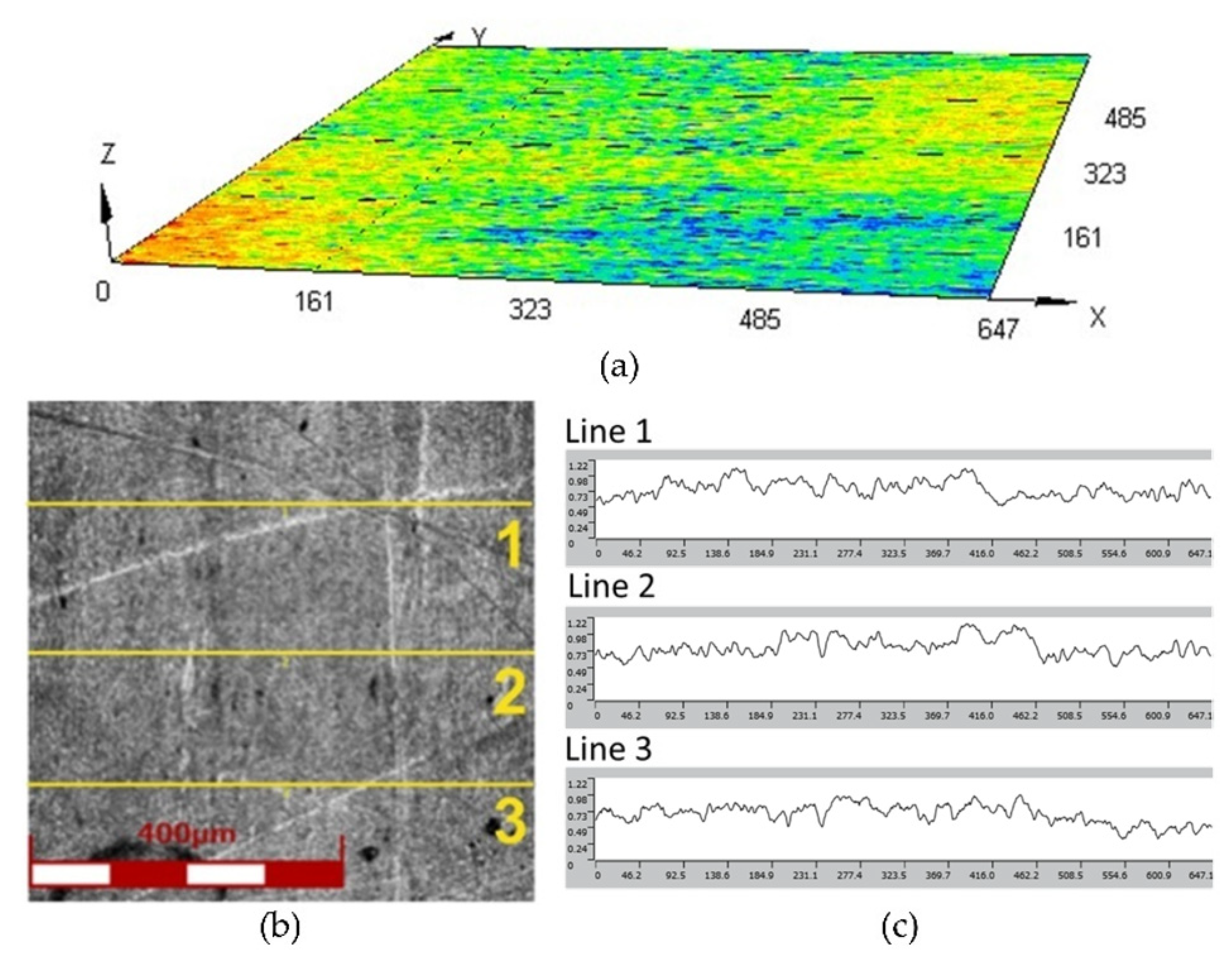
Figure 2.
(a) Surface topography, (b) view of surface of the Inconel 625 sheet metal and (c) linear surface roughness profiles used to determine average value of surface roughness parameters.
Figure 2.
(a) Surface topography, (b) view of surface of the Inconel 625 sheet metal and (c) linear surface roughness profiles used to determine average value of surface roughness parameters.
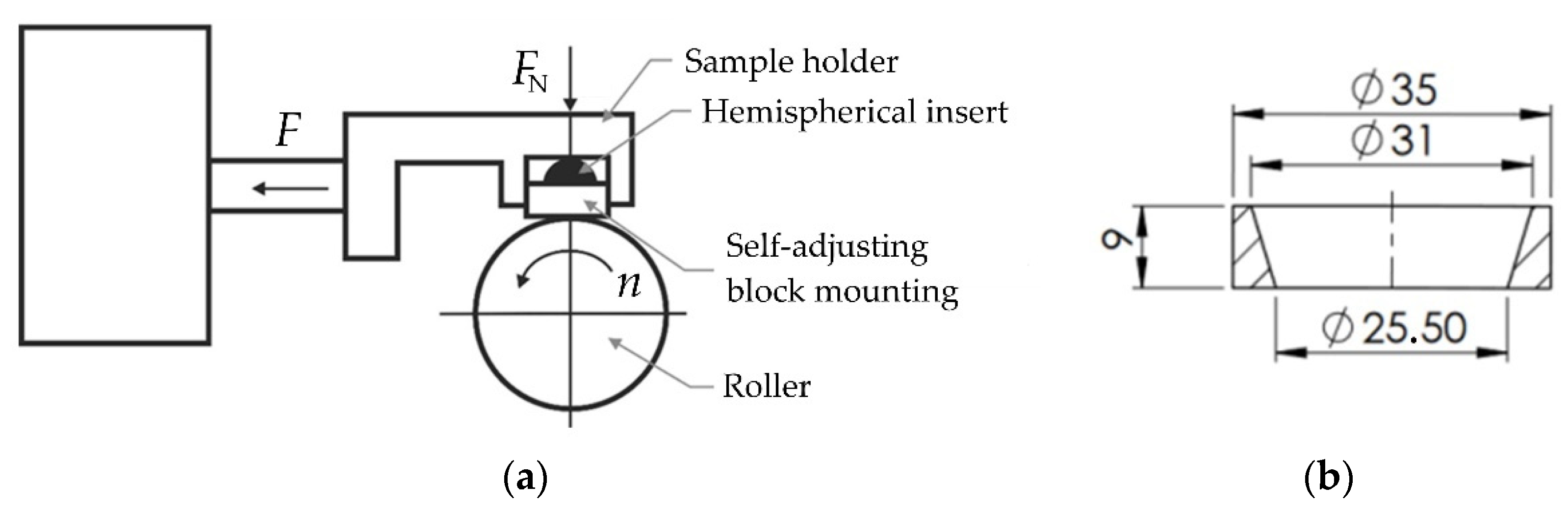
Figure 3.
(a) Principle of operation of the T-05 tester and (b) geometry and dimensions of the polyurethane countersample (unit: millimetre).
Figure 3.
(a) Principle of operation of the T-05 tester and (b) geometry and dimensions of the polyurethane countersample (unit: millimetre).
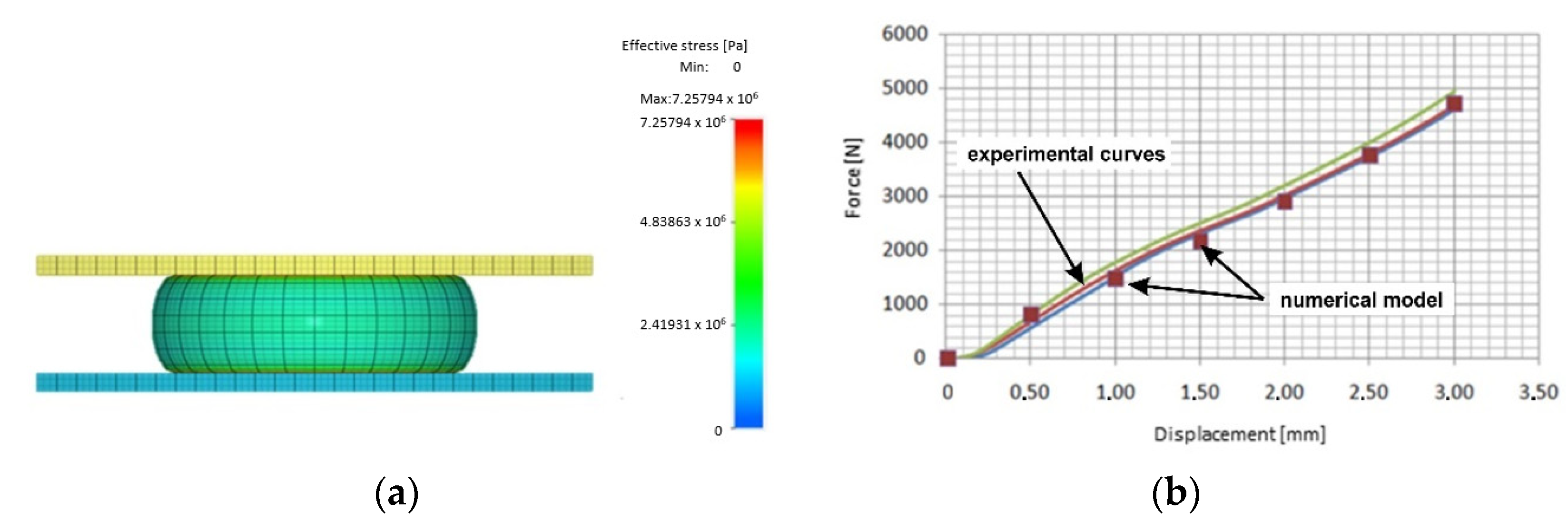
Figure 4.
(a) Simulated shape of the sample during the compression test and (b) fit of the experimental compression curve with the simulation results.
Figure 4.
(a) Simulated shape of the sample during the compression test and (b) fit of the experimental compression curve with the simulation results.
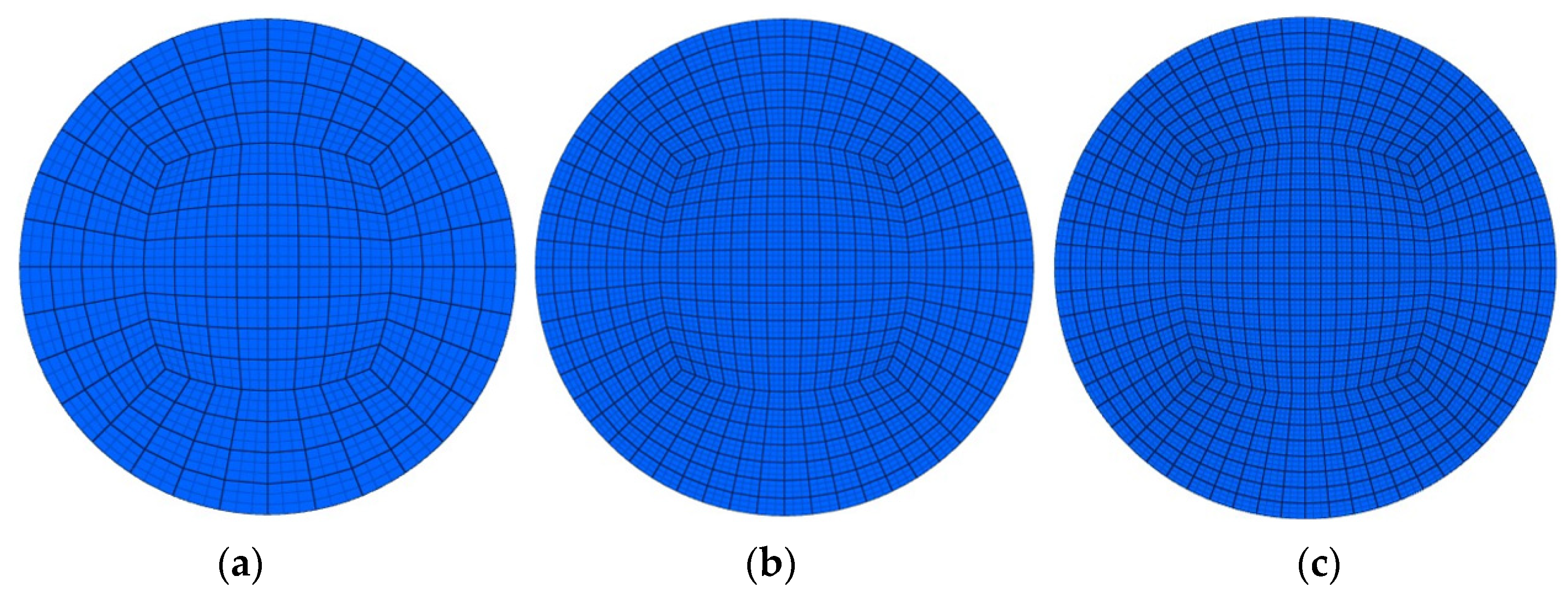
Figure 5.
Examples of finite element sizes used in the analysis: (a) type of coarse mesh with 8-node hexahedra elements; (b) type of medium mesh with quadratic 27-node hexahedron elements; (c) type of fine mesh with cubic 64-node hexahedron elements.
Figure 5.
Examples of finite element sizes used in the analysis: (a) type of coarse mesh with 8-node hexahedra elements; (b) type of medium mesh with quadratic 27-node hexahedron elements; (c) type of fine mesh with cubic 64-node hexahedron elements.
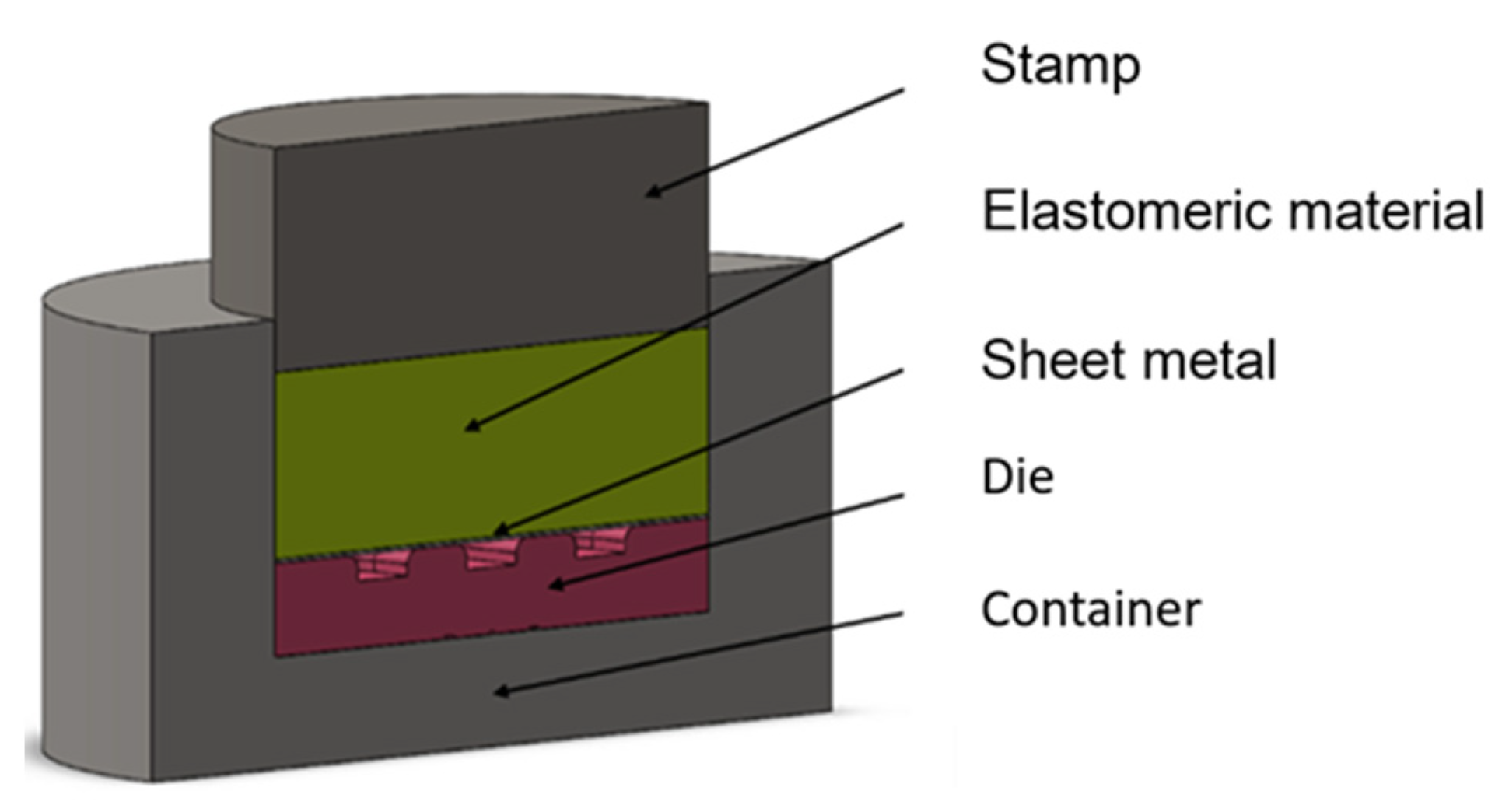
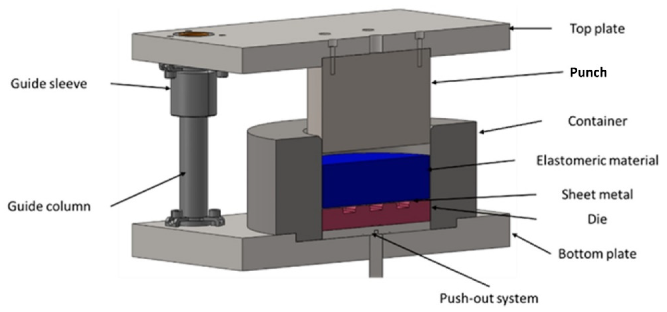
Figure 6.
Cross-section of a 3D model of a stamping die used for numerical simulations.
Figure 6.
Cross-section of a 3D model of a stamping die used for numerical simulations.
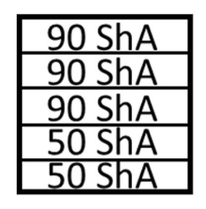
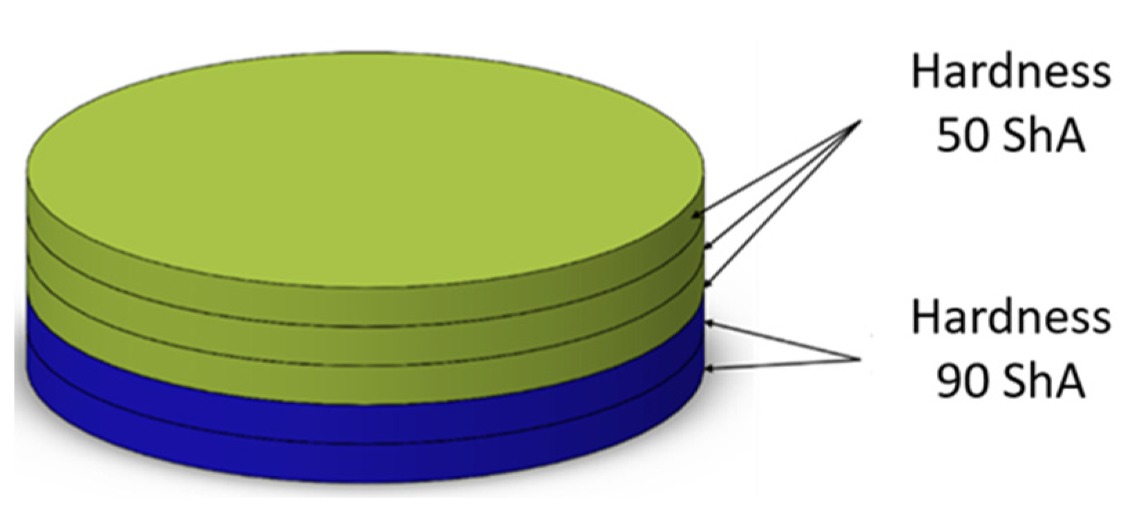
Figure 7.
Polyurethane punch configuration with five layers of inserts of different hardnesses (3 × 50 ShA + 2 × 90 ShA).
Figure 7.
Polyurethane punch configuration with five layers of inserts of different hardnesses (3 × 50 ShA + 2 × 90 ShA).
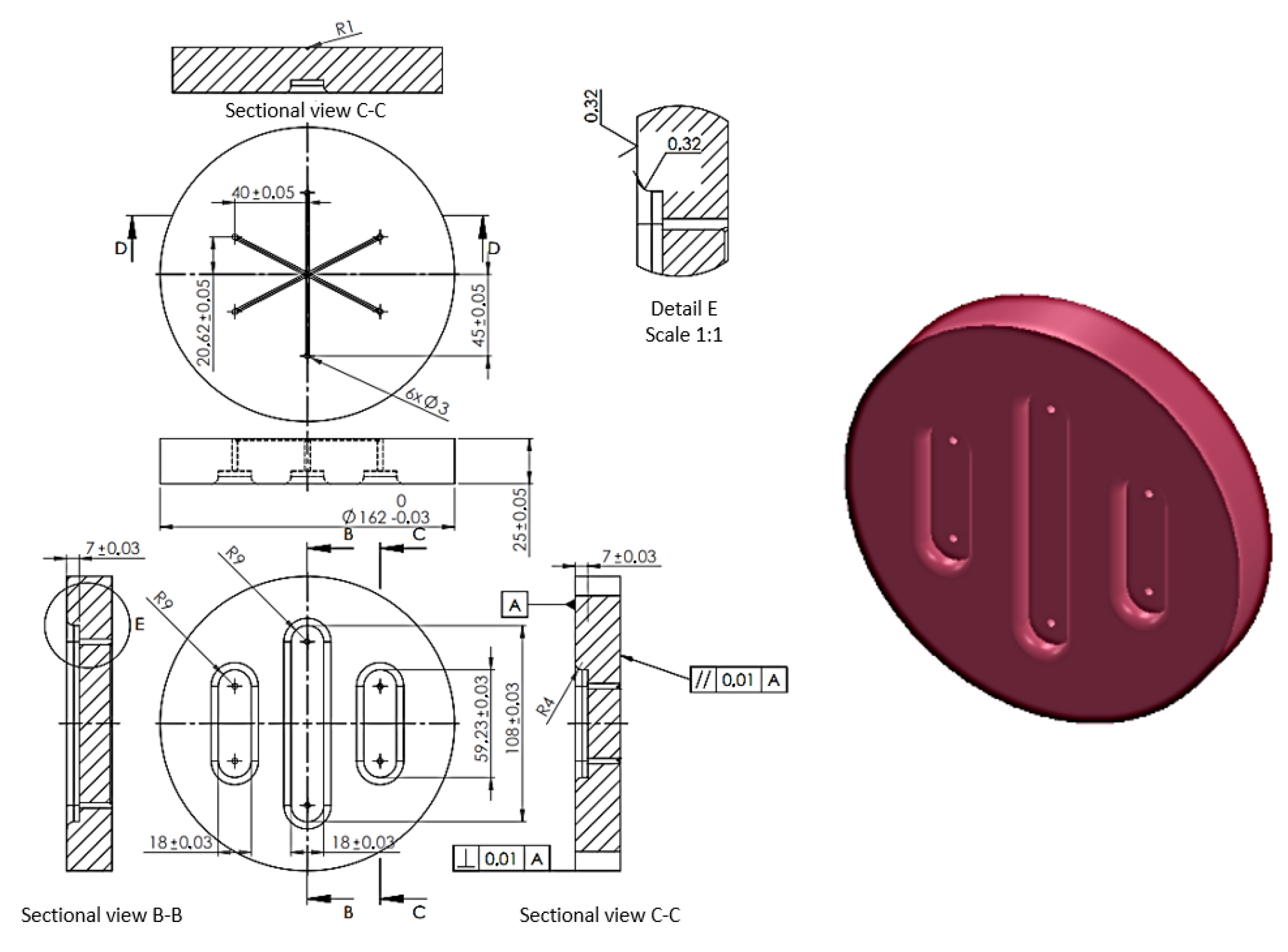
Figure 8.
Shape and dimensions of the die used to form Inconel 625 sheet metals (unit: millimetre).
Figure 8.
Shape and dimensions of the die used to form Inconel 625 sheet metals (unit: millimetre).
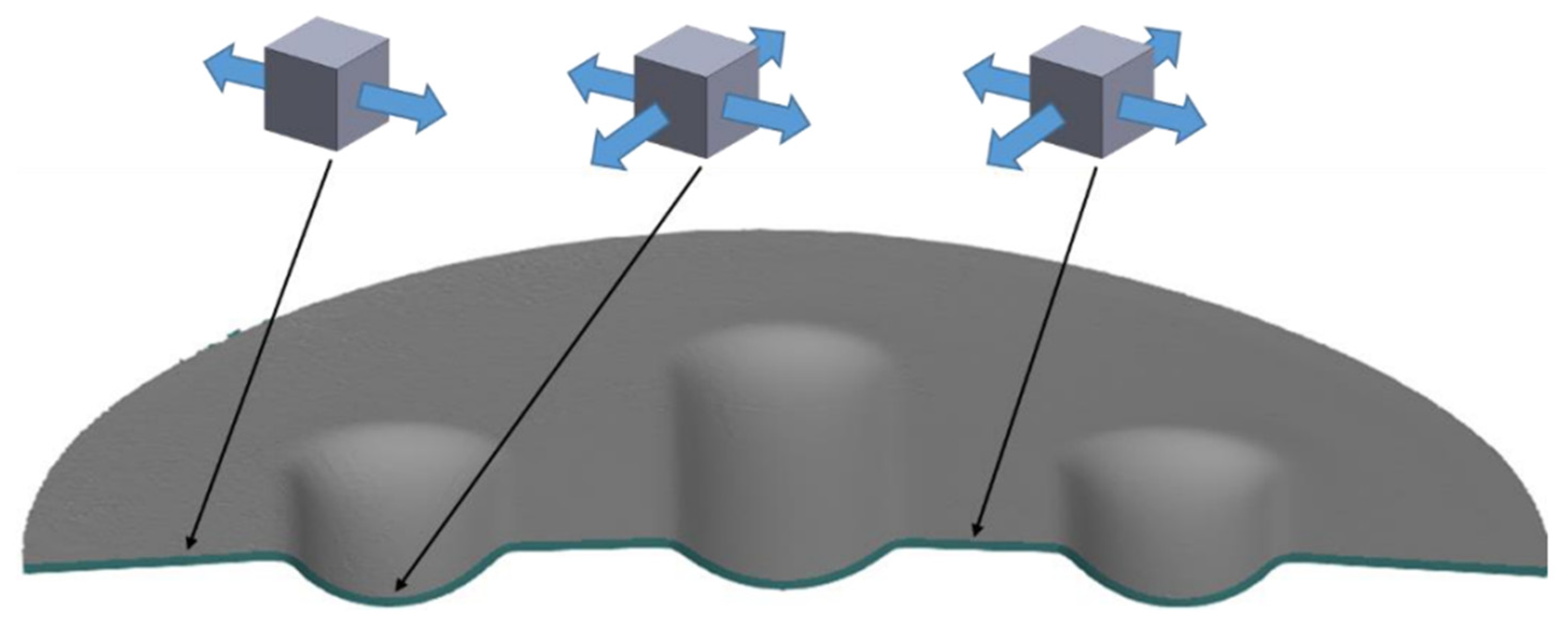
Figure 9.
Cross-section of a formed element with marked stress states in selected areas.
Figure 9.
Cross-section of a formed element with marked stress states in selected areas.
Figure 10.
Three-dimensional model of the stamping die.
Figure 10.
Three-dimensional model of the stamping die.
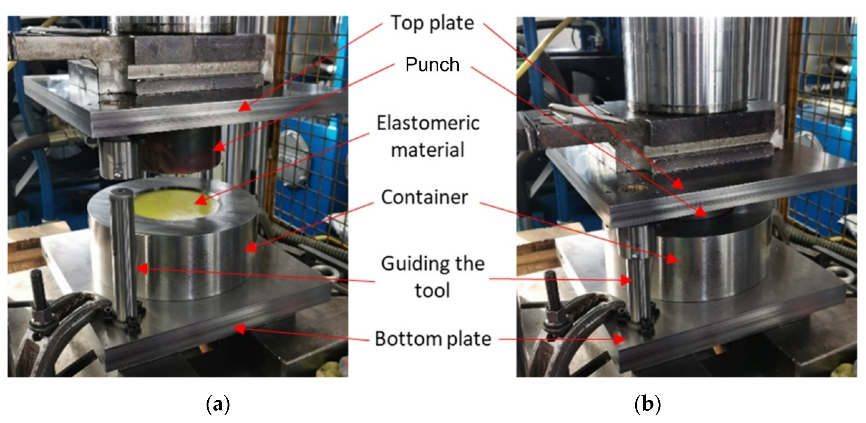
Figure 11.
Stamping die (a) mounted on a press and (b) during forming.
Figure 11.
Stamping die (a) mounted on a press and (b) during forming.
Figure 12.
The 3D scan of the drawpiece from different perspectives.
Figure 12.
The 3D scan of the drawpiece from different perspectives.
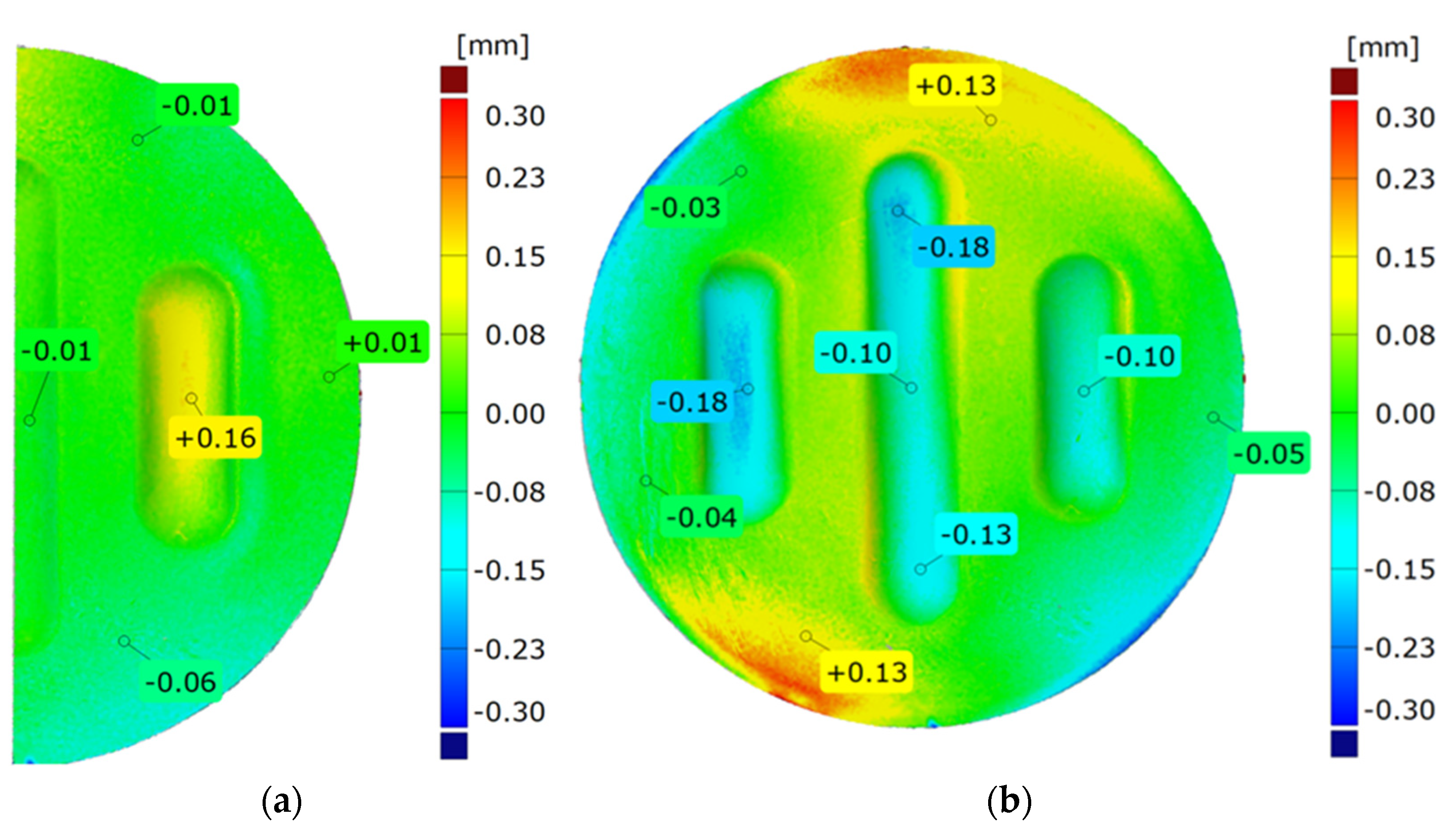
Figure 13.
Example result of the surface flatness measurement.
Figure 13.
Example result of the surface flatness measurement.
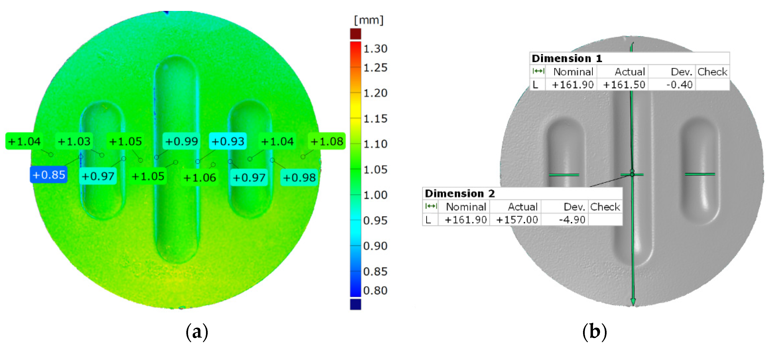
Figure 14.
Example result of measuring (a) the thickness of the drawpiece and (b) the change in drawpiece diameter after the forming process.
Figure 14.
Example result of measuring (a) the thickness of the drawpiece and (b) the change in drawpiece diameter after the forming process.
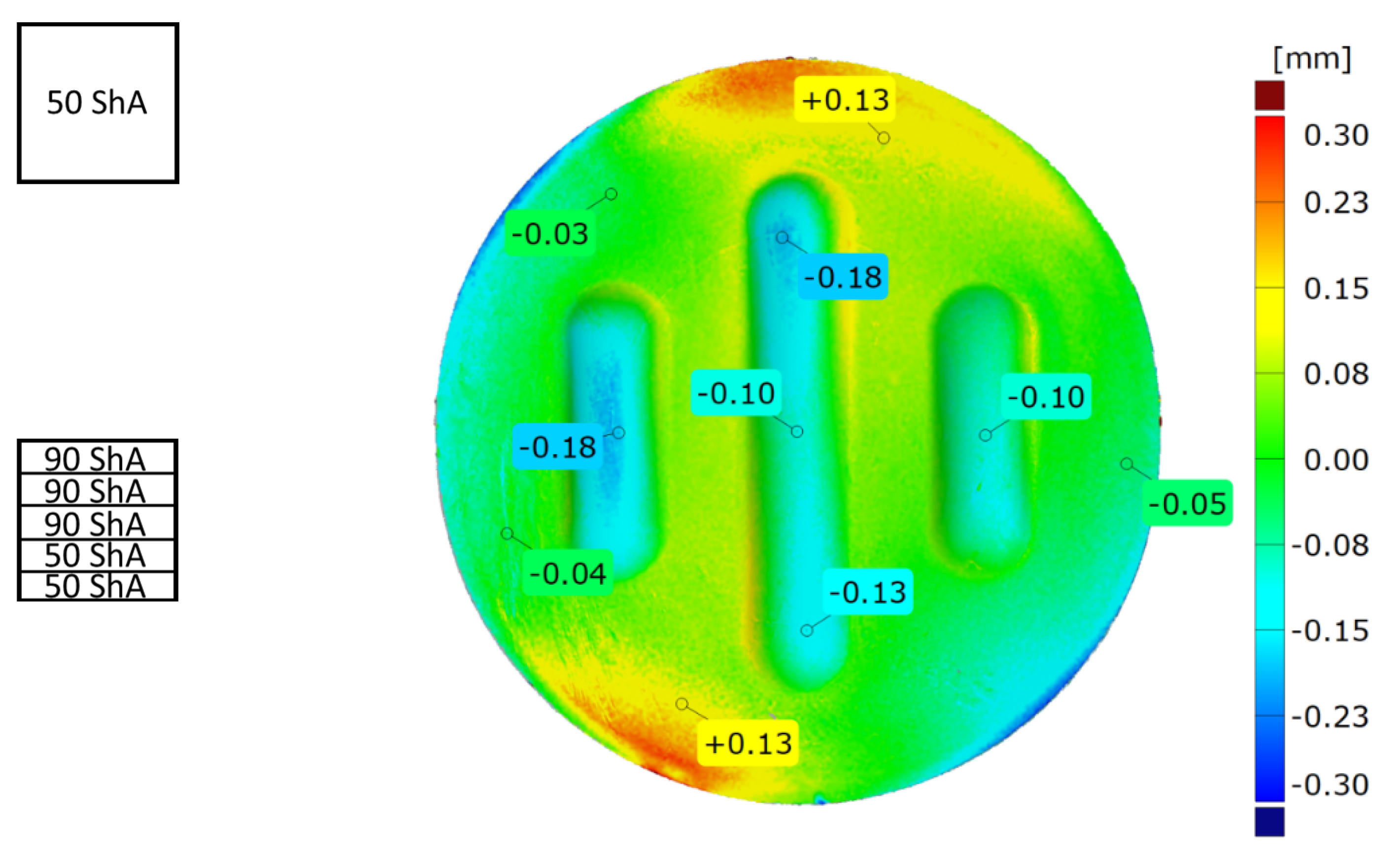
Figure 15.
Example results for (a) the strain uniformity and (b) the difference in forming depth.
Figure 15.
Example results for (a) the strain uniformity and (b) the difference in forming depth.
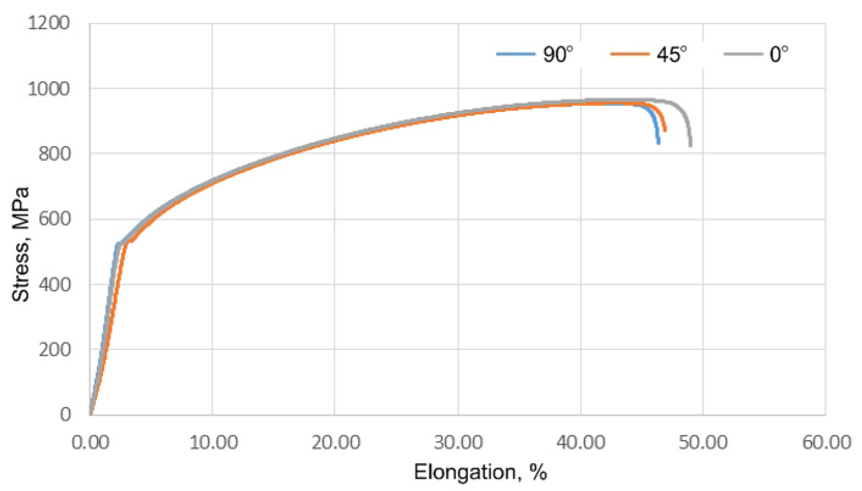
Figure 16.
Tensile curves of samples composed of Inconel 625 sheet.
Figure 16.
Tensile curves of samples composed of Inconel 625 sheet.
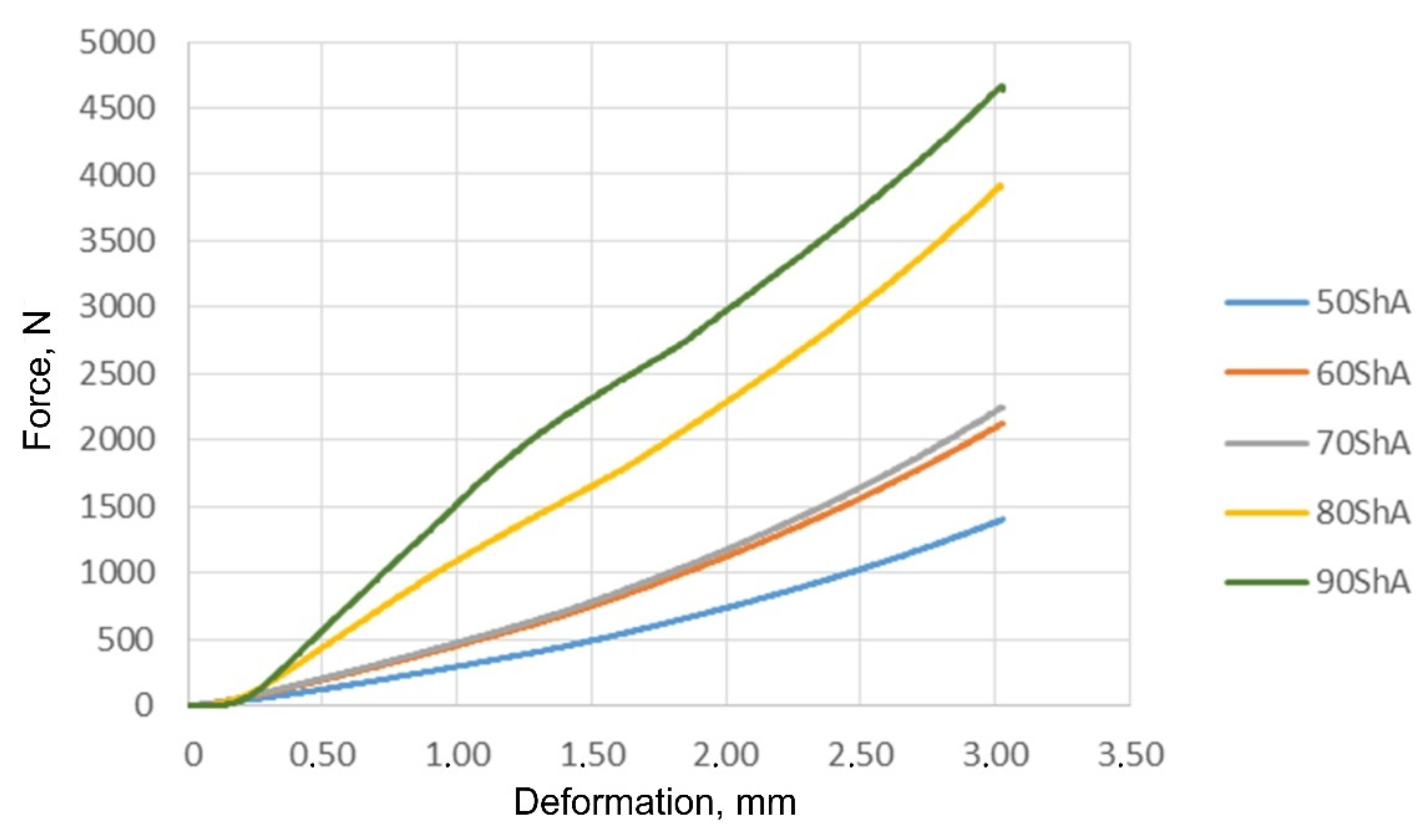
Figure 17.
Results of the uniaxial compression test of polyurethane samples.
Figure 17.
Results of the uniaxial compression test of polyurethane samples.
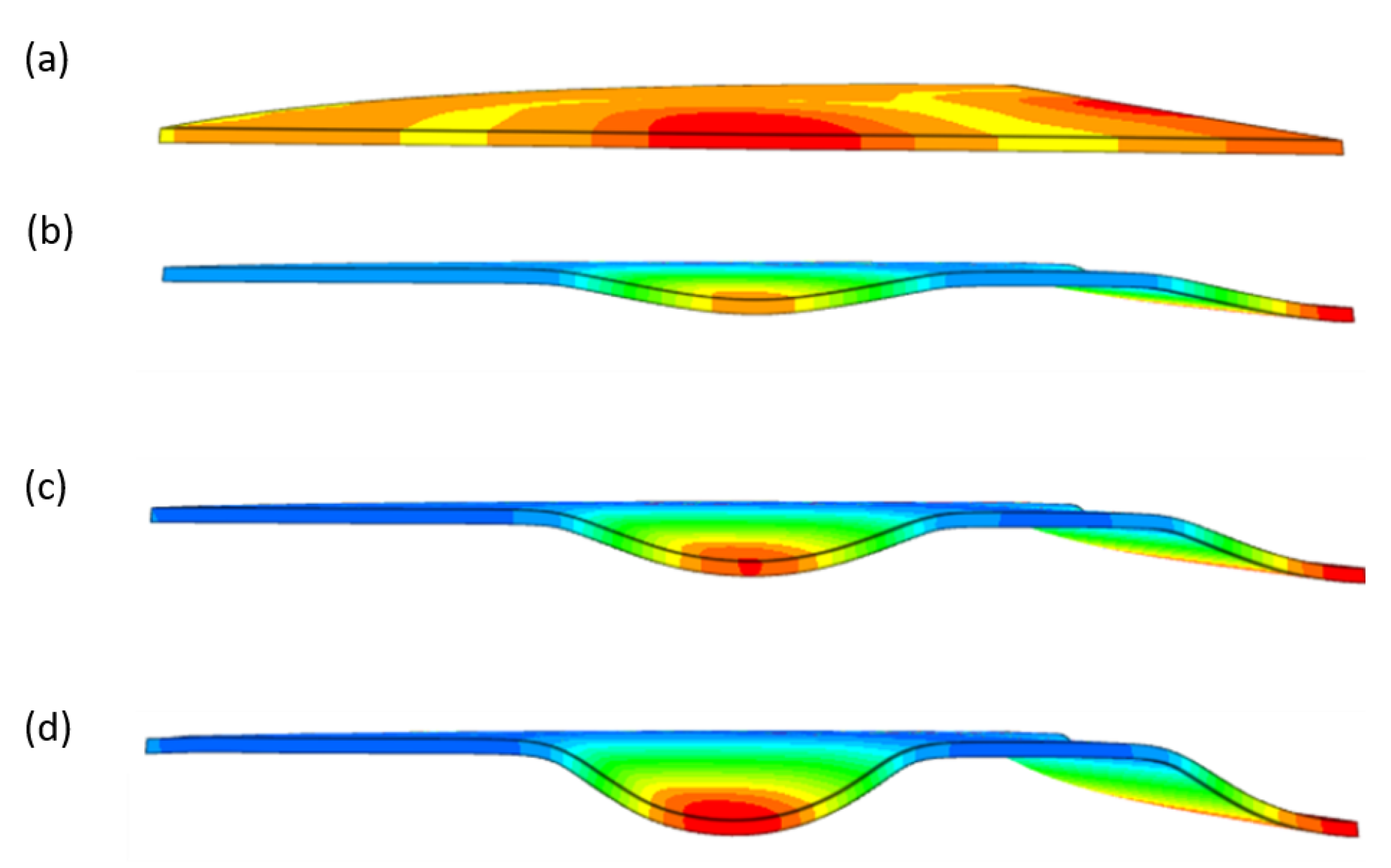
Figure 18.
Subsequent stages of forming the element for (a) 20%, (b) 40%, (c) 60% and (d) 90% of simulation time.
Figure 18.
Subsequent stages of forming the element for (a) 20%, (b) 40%, (c) 60% and (d) 90% of simulation time.
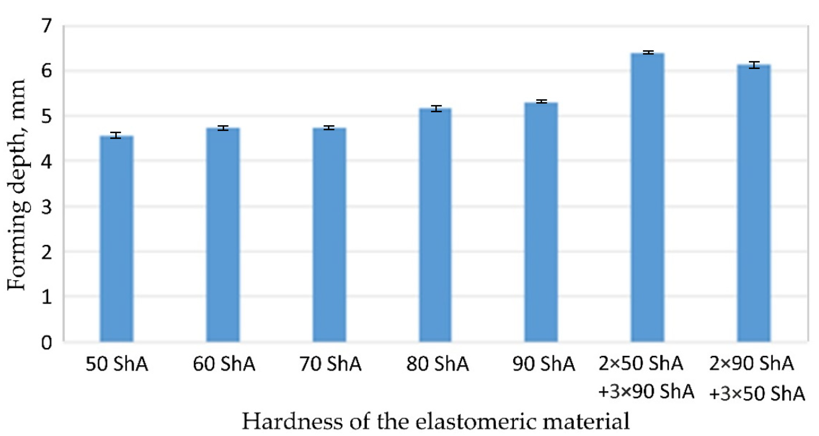
Figure 19.
The influence of the hardness of polyurethane inserts on forming depth.
Figure 19.
The influence of the hardness of polyurethane inserts on forming depth.
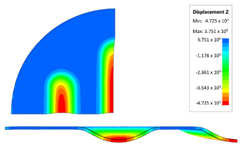
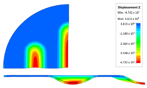
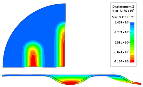
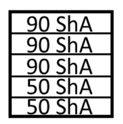
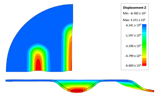
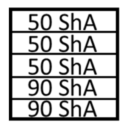
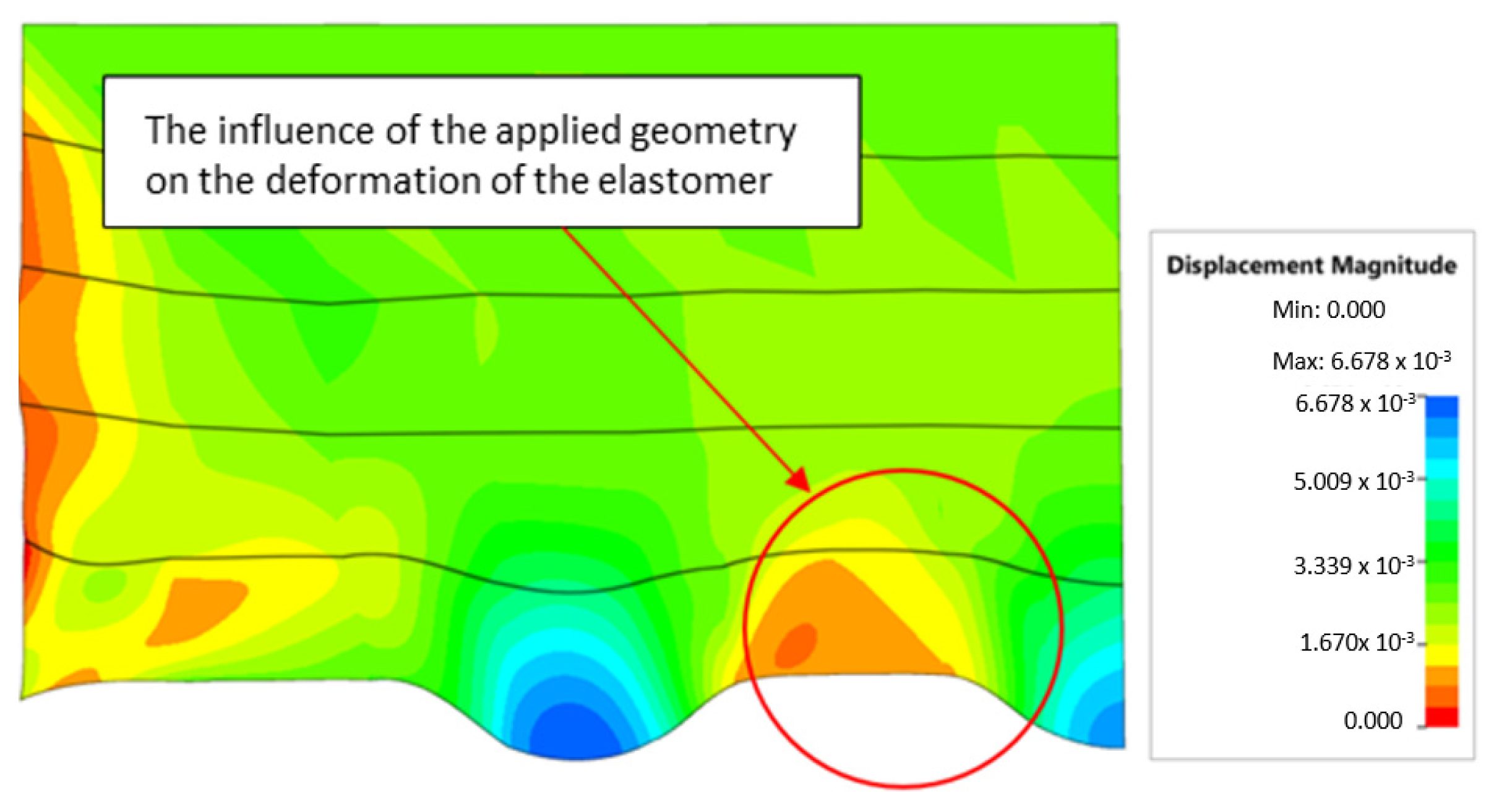
Figure 20.
The influence of die geometry on the deformation of the polyurethane punch consisting of five layers of different hardnesses 2 × 50 ShA + 3 × 90 ShA.
Figure 20.
The influence of die geometry on the deformation of the polyurethane punch consisting of five layers of different hardnesses 2 × 50 ShA + 3 × 90 ShA.
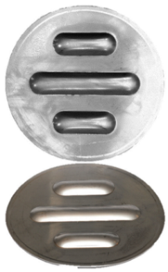
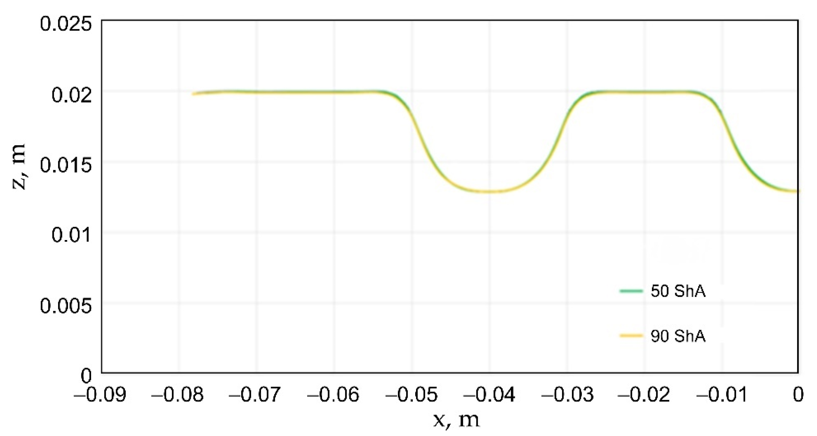
Figure 21.
Comparison of the geometry of drawpieces obtained using polyurethane inserts with a hardness of 50 ShA and 90 ShA using a forming force of 1000 kN.
Figure 21.
Comparison of the geometry of drawpieces obtained using polyurethane inserts with a hardness of 50 ShA and 90 ShA using a forming force of 1000 kN.
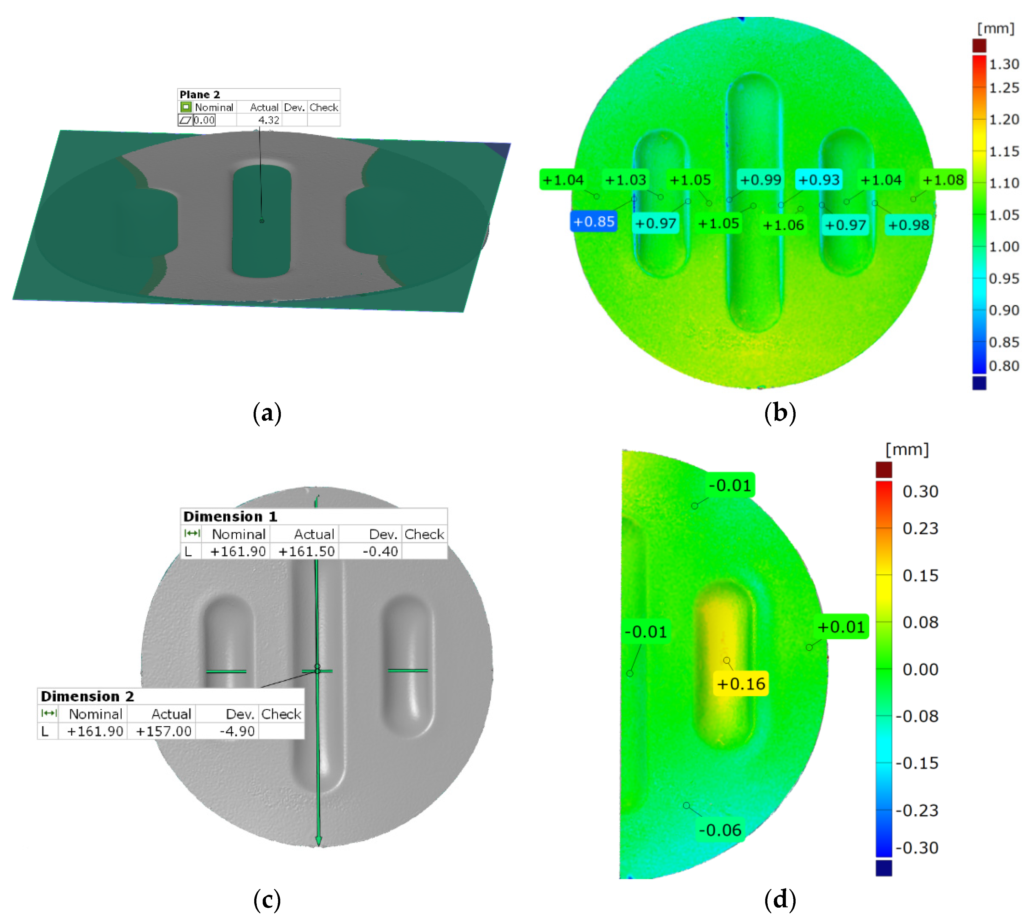
Figure 22.
Results of measuring the geometry of the drawpieces formed using five inserts with a hardness of 50 ShA: (a) surface flatness, (b) thickness, (c) changes in the diameter of the workpiece and (d) uniformity of forming.
Figure 22.
Results of measuring the geometry of the drawpieces formed using five inserts with a hardness of 50 ShA: (a) surface flatness, (b) thickness, (c) changes in the diameter of the workpiece and (d) uniformity of forming.
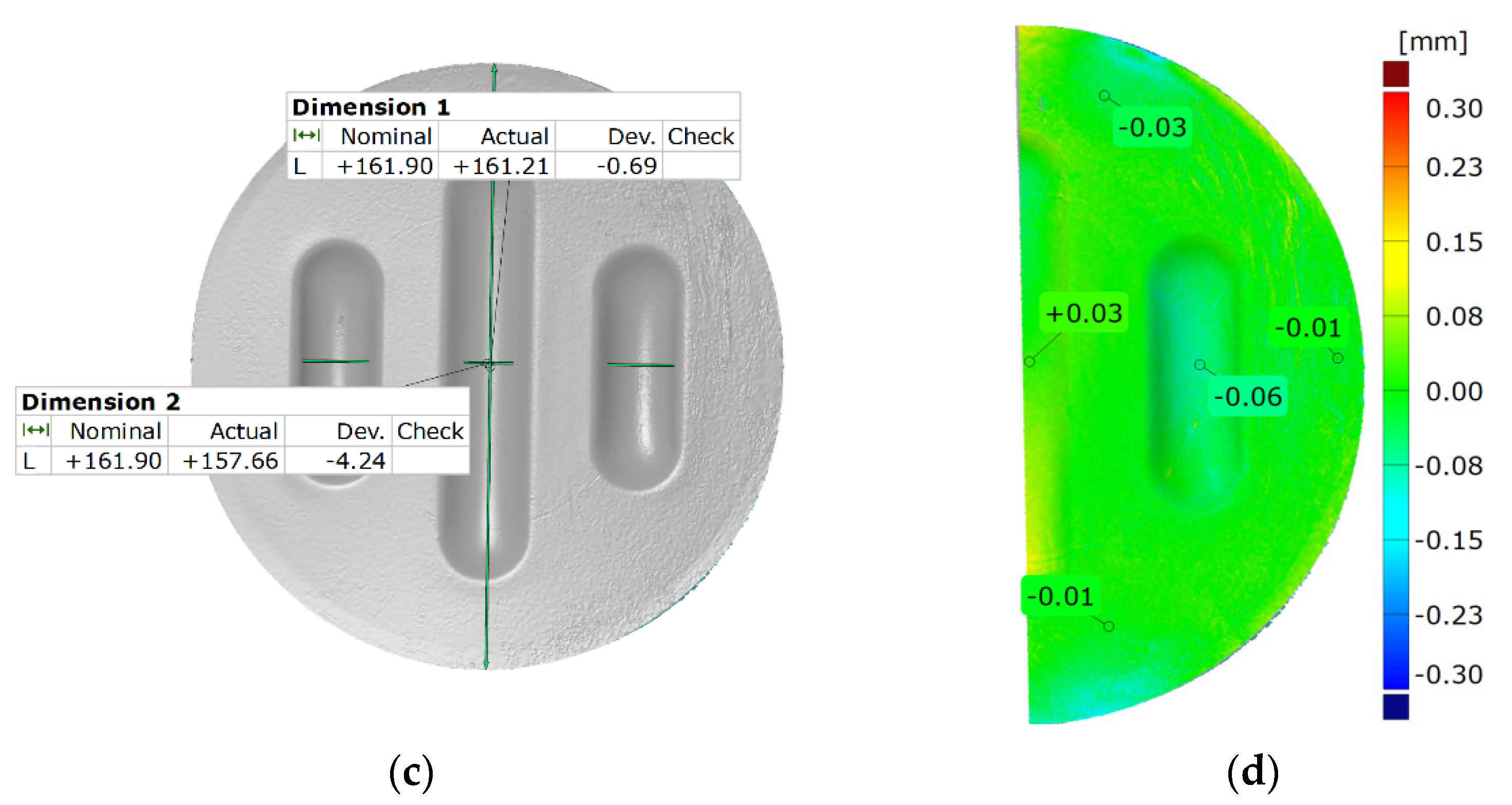
Figure 23.
Results of measuring the geometry of the drawpieces formed using two inserts with a hardness of 50 ShA and three inserts with a hardness of 90 ShA: (a) surface flatness, (b) thickness, (c) changes in the diameter of the workpiece and (d) uniformity of forming.
Figure 23.
Results of measuring the geometry of the drawpieces formed using two inserts with a hardness of 50 ShA and three inserts with a hardness of 90 ShA: (a) surface flatness, (b) thickness, (c) changes in the diameter of the workpiece and (d) uniformity of forming.
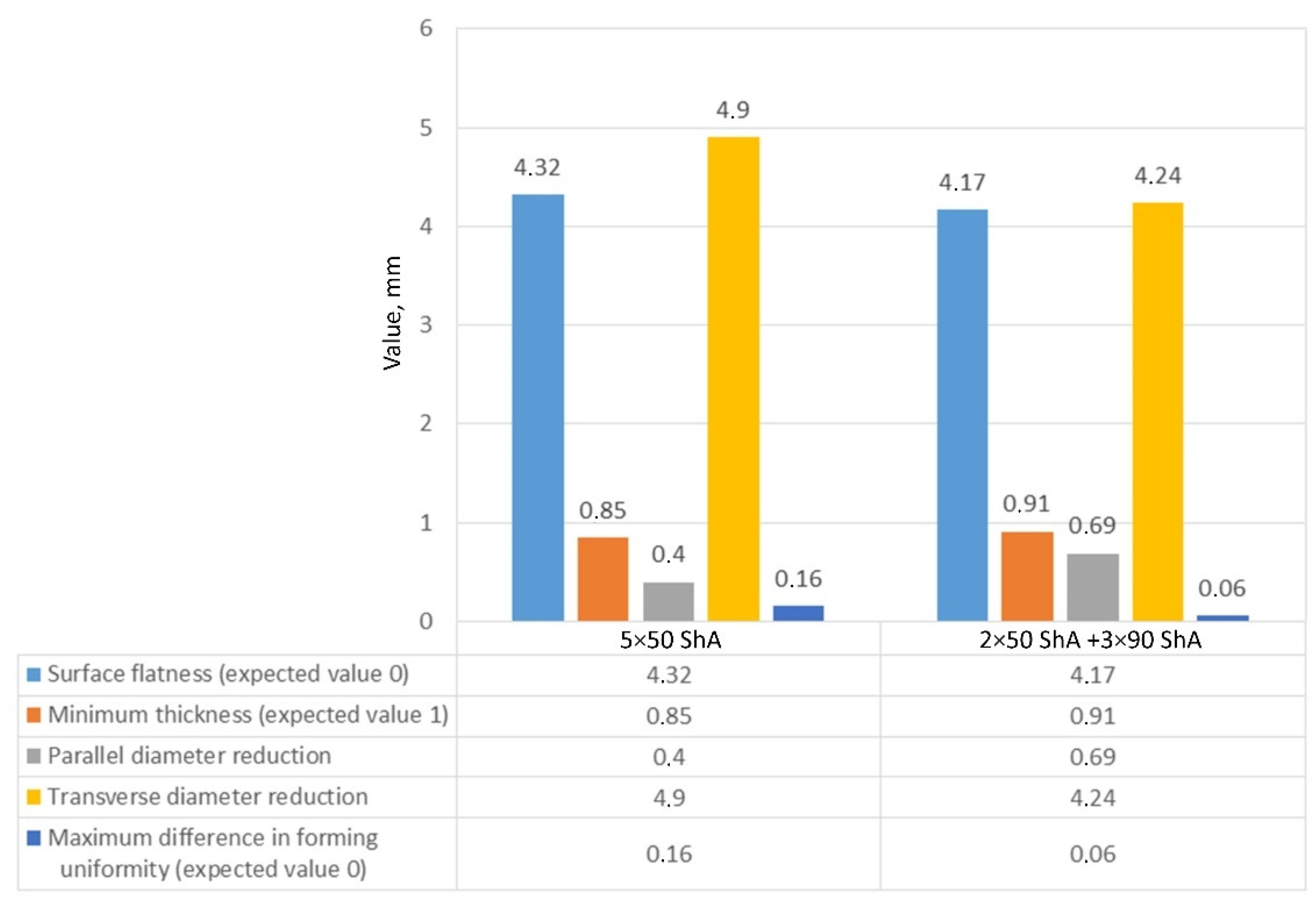
Figure 24.
Summary of measurement results of the geometry of drawpieces composed of Inconel 625 sheet metal.
Figure 24.
Summary of measurement results of the geometry of drawpieces composed of Inconel 625 sheet metal.
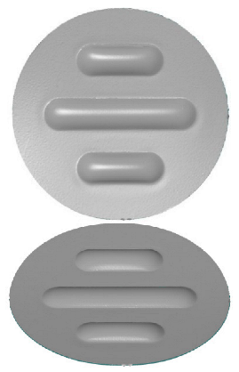
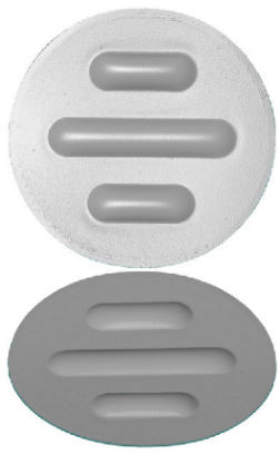
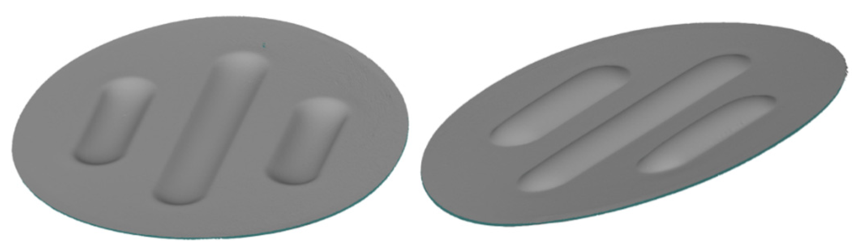
Figure 25.
Comparison of the drawpieces formed using two different configurations of polyurethane inserts: 5 × 50 ShA and 2 × 50 ShA + 3 × 90 ShA.
Figure 25.
Comparison of the drawpieces formed using two different configurations of polyurethane inserts: 5 × 50 ShA and 2 × 50 ShA + 3 × 90 ShA.
Table 1.
Surface roughness parameters of polyurethane inserts.
Table 1.
Surface roughness parameters of polyurethane inserts.
Average Value of the
Surface Roughness Parameter | Hardness of the Polyurethane Insert |
|---|
| 50 ShA | 60 ShA | 70 ShA | 80 ShA | 90 ShA |
|---|
| Ra, μm | 0.337 μm | 0.191 μm | 0.204 μm | 1.228 μm | 0.894 μm |
| Rz, μm | 2.536 μm | 1.244 μm | 1.517 μm | 7.918 μm | 5.493 μm |
Table 2.
Material coefficients for polyurethane samples with varying hardnesses.
Table 2.
Material coefficients for polyurethane samples with varying hardnesses.
| Hardness of Polyurethane Sample | Coefficient K, Pa | Coefficient C1, Pa | Coefficient C2, Pa |
|---|
| 50 ShA | 4.0 × 10⁹ | 0.3 × 10⁶ | 0.15 × 10⁹ |
| 60 ShA | 4.1 × 10⁹ | 0.59 × 10⁶ | 0.19 × 10⁶ |
| 70 ShA | 4.2 × 10⁹ | 0.6 × 10⁶ | 0.2 × 10⁶ |
| 80 ShA | 4.8 × 10⁹ | 1.6 × 10⁶ | 0.11 × 10⁶ |
| 90 ShA | 4.8 × 10⁹ | 2.1 × 10⁶ | 0.1 × 10⁶ |
Table 3.
Results of the basic mechanical parameters of Inconel 625 sheet.
Table 3.
Results of the basic mechanical parameters of Inconel 625 sheet.
| Sample Orientation | Ultimate Tensile Stress Rm, MPa | Yield Stress Rp0.2, MPa | Elongation A, % |
|---|
| 0° | 966.1 (±5) | 526.5 (±3) | 49.4 (±2) |
| 45° | 955.9 (±4) | 532.5 (±4) | 47.4 (±2.5) |
| 90° | 954.4 (±4) | 521.6 (±5) | 46.8 (±3) |
Table 4.
Anisotropy coefficients of Inconel 625 sheet.
Table 4.
Anisotropy coefficients of Inconel 625 sheet.
| Coefficient of Normal Anisotropy | Coefficient of Planar Anisotropy |
|---|
| 1.22 (±0.05) | −0.64 (±0.05) |
Table 5.
Results of the hardness measurements of polyurethane samples.
Table 5.
Results of the hardness measurements of polyurethane samples.
| Nominal Hardness, ShA | Number of Measurement | Measured Average Hardness, ShA |
|---|
| 1 | 2 | 3 | 4 | 5 |
|---|
| 50 | 50 | 50 | 51 | 51 | 52 | 50.7 |
| 60 | 62 | 61 | 62 | 62 | 64 | 61.8 |
| 70 | 64 | 66 | 63 | 63 | 66 | 65.3 |
| 80 | 78 | 79 | 78 | 80 | 81 | 79.3 |
| 90 | 89 | 89 | 88 | 90 | 90 | 89.3 |
Table 6.
Wear parameters and COF of polyurethane countersamples and Inconel 625 sample.
Table 6.
Wear parameters and COF of polyurethane countersamples and Inconel 625 sample.
| Parameter | Hardness of Polyurethane Countersample |
|---|
| 50 ShA | 60 ShA | 70 ShA | 80 ShA | 90 ShA |
|---|
| Weight loss of polyurethane countersample Δmcs, % | 0.4031 | 0.1448 | 0.1956 | 0.0116 | 0.0762 |
| Weight loss of Inconel 625 sample Δms, % | 0.1958 | −0.041 | 0.2483 | −0.063 | −0.0328 |
| Average COF | 0.465 | 0.526 | 0.622 | 0.545 | 0.263 |
Table 7.
Results of the maximum depth of emboss in the Inconel 625 alloy sheet for individual variants of the polyurethane inserts.
Table 8.
Summary of the results of forming drawpieces with a pressure of 1000 kN.


 ,
, 


