Article

Microstructure, Texture, and Mechanical Properties of Friction Stir Spot-Welded AA5052-H32: Influence of Tool Rotation Rate

by
Mohamed M. Z. Ahmed
1,*,
Mohamed M. El-Sayed Seleman
2,
Ibrahim Albaijan
1 and
Ali Abd El-Aty
1,3
1
Department of Mechanical Engineering, College of Engineering at Al Kharj, Prince Sattam Bin Abdulaziz University, Al Kharj 11942, Saudi Arabia
2
Department of Metallurgical and Materials Engineering, Faculty of Petroleum and Mining Engineering, Suez University, Suez 43512, Egypt
3
Mechanical Engineering Department, Faculty of Engineering-Helwan, Helwan University, Cairo 11795, Egypt
*
Author to whom correspondence should be addressed.
Materials 2023, 16(9), 3423; https://doi.org/10.3390/ma16093423
Submission received: 26 March 2023 / Revised: 15 April 2023 / Accepted: 24 April 2023 / Published: 27 April 2023

Abstract

:
Friction stir spot welding (FSSW) of similar AA5052-H32 joints has numerous benefits in shipbuilding, aerospace, and automotive structural applications. In addition, studying the role of tool rotation speed on the microstructure features, achieved textures, and joint performance of the friction stir spot-welded (FSSWed) joint still needs more systematic research. Different FSSWed AA5052-H32 lap joints of 4 mm thickness were produced at different heat inputs using three tool rotation speeds of 1500, 1000, and 500 rpm at a constant dwell time of 2 s. The applied thermal heat inputs for achieving the FSSW processes were calculated. The produced joints were characterized by their appearance, macrostructures, microstructures, and mechanical properties (hardness contour maps and maximum tensile–shear load) at room temperature. The grain structure and texture developed for all the FSSWed joints were deeply investigated using an advanced electron backscattering diffraction (EBSD) technique and compared with the base material (BM). The main results showed that the average hardness value of the stir zone (SZ) in the welded joints is higher than that in the AA5052-H32 BM for all applied rotation speeds, and it decreases as the rotation speed increases from 500 to 1000 rpm. This SZ enhancement in hardness compared to the BM cold-rolled grain structure is caused by the high grain refining due to the dynamic recrystallization associated with the FSSW. The average grain size values of the stir zones are 11, 9, and 4 µm for the FSSWed joints processed at 1500, 1000, and 500 rpm, respectively, while the BM average grain size is 40 µm. The simple shear texture with B/-B components mainly dominates the texture. Compared to the welded joints, the joint processed at 500 rpm and a 2 s duration time attains the highest tensile-shear load value of 4330 N. This value decreases with increasing rotation speed to reach 2569 N at a rotation speed of 1500. After tensile testing of the FSSWed joints, the fracture surface was also examined and discussed.

1. Introduction

Using lightweight materials in transportation industries has become a popular strategy for reducing power use and fuel consumption [1,2,3]. Aluminum-based materials can satisfy the requirements for developing lightweight vehicles since aluminum has lower specific gravity than steel, high corrosion resistance, a high strength-to-weight ratio, good weldability, impact resistance, and recycling potential. The Al-Mg series alloys (5XXX Al alloys) have drawn significant attention for automotive and marine structural applications [4,5,6]. One of the most important alloys in this group is AA5052 aluminum alloy. This alloy is widely utilized in the manufacture of automotive components, vessels, and ships, and it may be welded using different fusion welding methods, including metal inert gas (MIG) [7,8], tungsten inert gas (TIG) [9,10], and resistance spot welding (RSW) [11,12]. These conventional welding processes depend on phase regulator transistorized power sources, which consume a lot of energy and require extended cooling times. Furthermore, welding defects such as micro-voids, solidification cracking, and joint distortion cannot be prevented [13,14,15]. To overcome these fusion welding defects, friction-based, solid-state welding technologies such as friction stir welding (FSW) [16,17] and its derivative friction stir spot welding (FSSW) [18,19,20] can be utilized.
The FSSW process is a new development in FSW, which was suggested and applied by the Mazda motor corporation in 1993 [21]. FSSW is a solid-state joining technology that produces a spot weld by plunging the rotating tool into and out of the overlapping sheet materials at a single location. It has attracted the attention of many researchers due to its advantages, such as high joint efficiency, low joint distortion, low cost, ease of handling, and a clean working environment [22].
The FSSW procedure variables, including tool type and profile [23,24], rotation speed [25,26,27], plunge rate [28,29,30], and dwell time [31,32,33], govern the joint efficiency of friction stir spot welds. FSSW has been successfully utilized to weld various kinds of aluminum alloys, including AA7050 [34], AA6082-T6 [35], AA6061-T6 [36], AA6061-T4 [37], AA5182-O [38], AA5052-H112 [27], AA5052-H32 [30], AA3003-H12 [39], and AA2024-T3 [40]. The tool geometry results in the typical welded structure of the FSSW and determines the pattern of material flow during the stirring process. Furthermore, the tool geometry influences the hook dimensions and stir zone width [41,42,43,44]. During the welding process at a constant rotation speed, the heat generation, material plasticization around the pin, weld shape, and, consequently, the welded joint performance are governed by the dwell time and tool penetration [28,45]. When the dwell time is kept constant, the tool rotation speed is considered one of the crucial FSSW parameters [46,47].
The impact of tool rotation speed on the joint quality of the FSSW materials has been studied in some works [38,48,49,50]. These studies have found that rotation speed affects welding performance in various ways. Zhang et al. [30] analyzed tensile test results from FSSW AA5052-H112 lap joints and concluded that the joint performance decreases with increasing the rotation speed. Cao and Jahazi [51] concluded that the joint strength in the FSSW AZ31B-H24 magnesium alloy welds initially increases with increasing tool rotation speed but decreases with a further increase. Rojikin et al. [52] also reported a similar trend for the FSSW dissimilar AA5052-steel SS400 joints. Ahmed et al. [53] remarked a noticeable heat influence on the joint surface quality of the FSSW high-manganese TWIP steel (0.6 wt.% C, 22 wt.% Mn, 0.3 wt.% V) lap joints around the welded region that expanded into a sizable area with an increase in rotation speed.
Based on the above literature, the FSSW procedure was accomplished with severe plastic deformation, and the quality of the formed welds was considerably impacted by the quantity of heat input used. Furthermore, because FSSW is achieved in a shorter period of time than FSW, it promotes less heat-input energy. Thus, it is advised to use a high heat input to enhance the joint quality of friction stir welds. Moreover, aluminum alloys possess excellent thermal conductivity, and as a result, the high heat input may result in a coarse microstructure in the stir zone and then a reduced joint strength of the spot welds. Additionally, optimizing the tool rotation speed is a challenge to provide an optimum heat input and well-structured joints, especially at a short dwell time.
Thus, understanding the effect of tool rotation speed on microstructure features and its impact on the mechanical properties of AA5052-H32 FSSW joints still requires a thorough investigation, particularly for a wide range of tool rotation speeds and a short duration time. Consequently, the objectives of the current work are to study the applicability of utilizing FSSW to join AA5052-H32 alloy sheets in 4 mm similar lap joints at the short dwell time of 2 s and various tool rotation rates of 500, 1000, and 1500 rpm. In addition, this work aimed to evaluate the produced joint performance for the different introduced heat inputs by the analysis of the achieved microstructural features in terms of grain size, misorientation angles, and textures. To achieve these objectives, 2 mm thick AA 5052 H32 cold-rolled aluminum alloy strips were FSSWed at different rotation speeds (500, 1000, and 1500 rpm) while applying a constant dwell time of 2 s to produce 4 mm thick similar spot lap joints. The applied thermal heat inputs for achieving the FSSW joints were determined. The joint appearance was evaluated. Finally, the mechanical properties of the joined specimens in terms of hardness map and maximum load-carrying capacity were examined and interpreted in light of an extensive EBSD study on the microstructure features and the crystallographic texture.

2. Experiments and Procedures

2.1. Base Material

The starting materials utilized in the current study were AA5052-H32 alloy sheets with a thickness of 2 mm, a length of 1000 mm, and a width of 1000 mm. The sheets were produced by Misr Aluminum Company “Egyptalum”, Egypt. The chemical composition and mechanical properties of the AA 5052-H32 Al alloy base material (BM) are given in Table 1.

2.2. FSSW Experiments

The AA 5052-H32 FSSW joints were processed utilizing a full-automatic FSW/FSSW machine (EG-FSW-M1) [54]. For the FSSW experiments, the sheets of AA 5052-H32 Al alloy were cut into strips with dimensions of 100 × 30 × 2 mm (length × width × thickness). These 5052 Al strips were jointed at various tool rotation speeds of 500, 1000, and 1500 rpm and a 2 s holding time in similar lap joints with a 30 mm overlap area. Other FSSW process variables, including tilt angle, plunge depth, and plunge rate, were kept constant at 0°, 3.2 mm, and 0.1 mm/s, respectively. The tool used in this study was made of hot-worked steel (AISI H13) and designed to have a cylindrical pin and a flat shoulder. The tool dimensions in terms of shoulder diameter, pin length, and pin diameter were 20, 3, and 5 mm, respectively, as given in Figure 1. Based on the previous works [43,55], the tool material and design were chosen. Aydin et al. [55] compared the role of various pin shapes (cylindrical, cylindrical with grooves, triangular, conical, and hexagonal) on the joint strength and the welded zone area for the FSSW AA6082-T6 joints at different dwell times and reported that the welds achieved using the cylindrical pins produced a wider effective weld width with a higher joint strength compared to the other pin profiles. In addition, Hirasawa et al. [43] concluded that the temperature distribution is axisymmetric during the stirring process when applying the cylindrical pin.

2.3. Spot-Welded Joints Characterization

A macrostructure and microstructure examination and a hardness evaluation were performed on the cross-section of the FSSWed joints. SiC papers were used to grind all specimens to a 2400-grit level. This process was followed by polishing in the presence of distilled water (DW) using a polishing cloth and 0.05 µm alumina paste. Etching of the surface-polished specimens was achieved using Keller’s reagent (6 mL nitric acid (HNO3), 3 mL hydrofluoric (HF), and 95 mL DW). Microstructural investigations were accomplished using an Olympus optical microscope (model BX41M-LED, Olympus, Tokyo, Japan). Moreover, the FSSW joints and BM microstructures were deeply investigated using an electron back-scattered diffraction (EBSD) technique equipped with a Quanta FEG 250 SEM FEI Company, Hillsboro, OR, USA. For the EBSD examination, the BM and the welded specimens were mechanically polished, then electro-polished at a temperature of −15 °C and 14 V for 1 h. The electrolyte solution was 70 vol.% methanol (CH3OH) and 30 vol.% of HNO3. Post-processing of the EBSD data was carried out using OIM software version OIM7.3, and for the grain size calculation, any two points paired with misorientation exceeding 2 degrees were considered a boundary. To evaluate the hardness values of the BM and the different FSSW zones for the different welding conditions, hardness testing was performed on the cross-sections of the FSSW lap joints, and the results were used to plot hardness contour maps. Hardness was measured using a Vickers hardness testing machine (Type HWDV-75, TTS Unlimited, Osaka, Japan) at the testing conditions of 5 N load and 15 s holding time. The cross-sections of the FSSW AA 5052-H32 joint were divided into four lines to represent the two welded Al strips, as given in Figure 2. The spacing between each pair of indentations was adjusted to 0.75 mm.
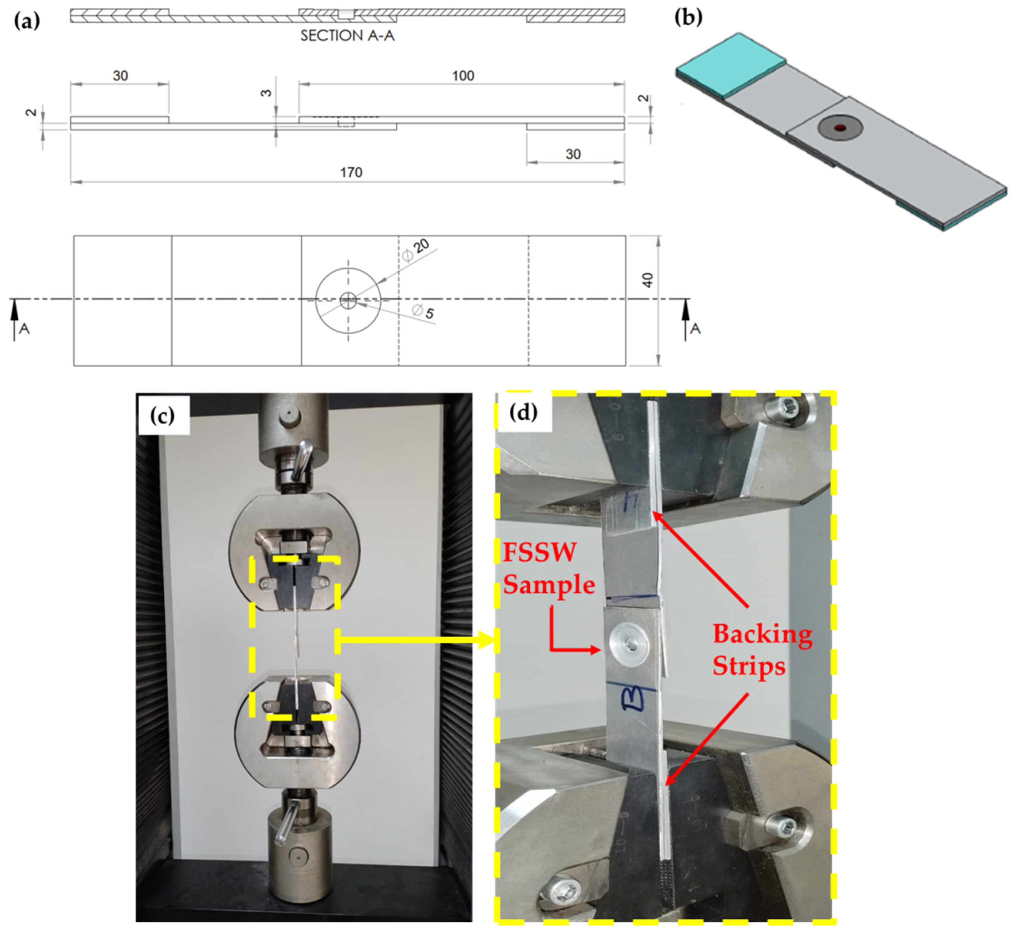
The tensile–shear tests were performed at room temperature using a universal tensile testing instrument (Model WDW-300D, Guangdong, China). For each tensile–shear test, at least three specimens were examined. All the tensile experiments were performed at 0.05 mm/sec crosshead speed. Figure 3 presents a drawing showing the tensile–shear test sample of the FSSWed AA5052 Al alloy joint. Two backing AA5052-H32 strips (30 mm length, 30 mm width, and 2 mm thickness) were used to ensure the applied axial load during tensile–shear testing. The fractured surfaces of the failed FSSWed joints were also examined using the SEM-Quanta FEG 250.

3. Results and Discussion

3.1. Joint Appearance

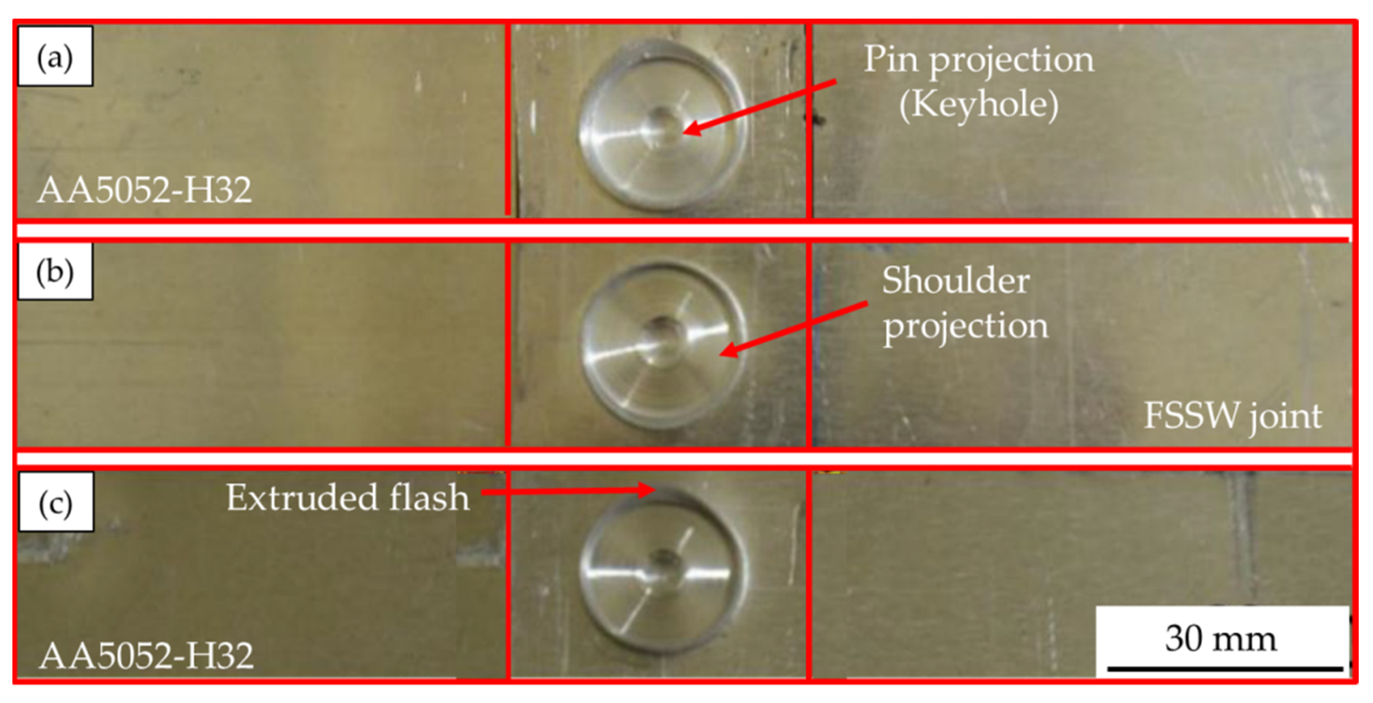
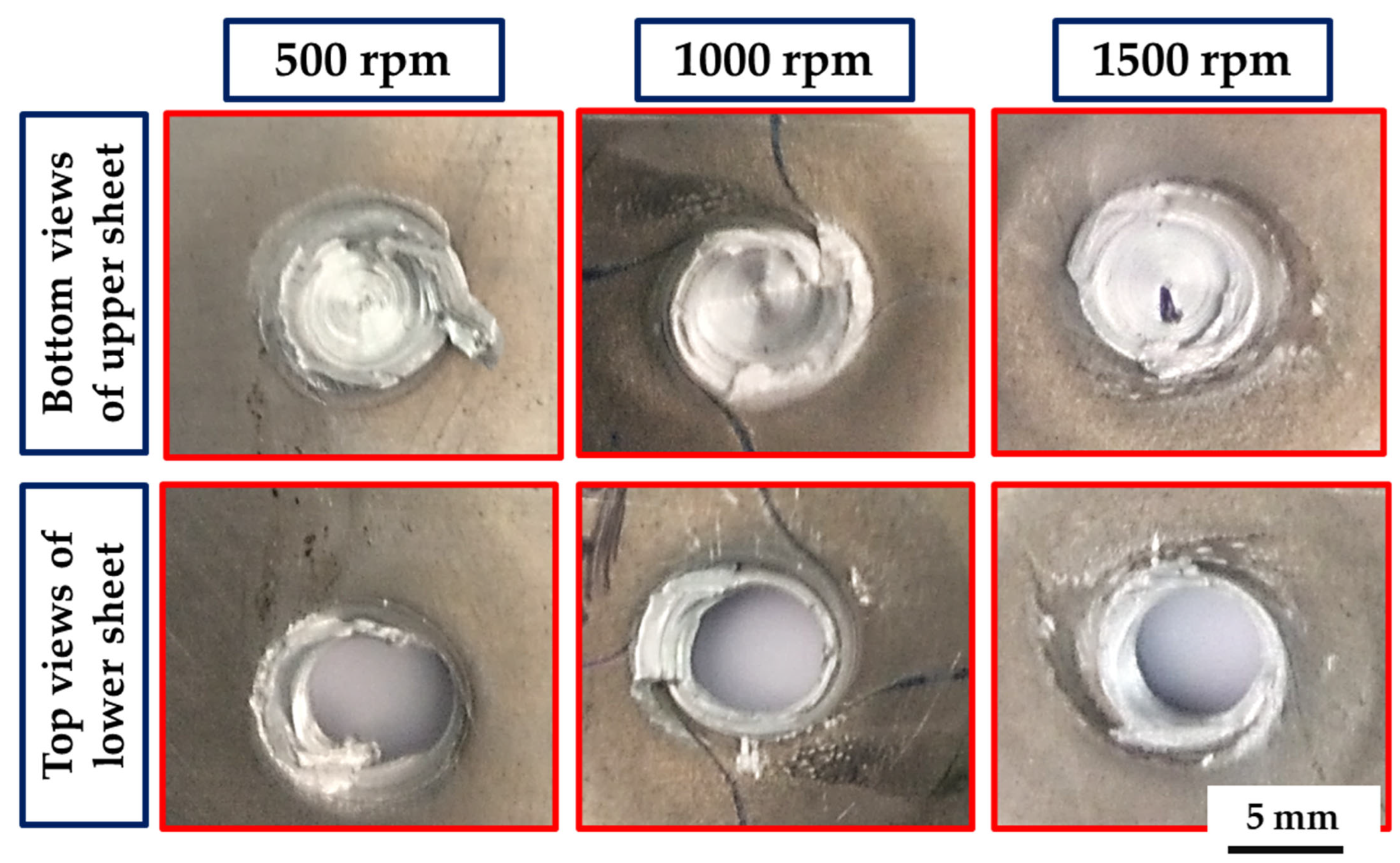
The top surfaces of the FSSW AA5052-H32 joints produced at a 2 s dwell time and rotation speeds of 500, 1000, and 1500 rpm are shown in Figure 4. It can be concluded that the chosen FSSW parameters are able to produce 4 mm thickness AA5052-H32 lap joints without any significant joint distortion. The formed keyhole and circular indentation of the shoulder projection, which serves as identifying characteristics of the FSSW joints, are detected for all the applied rotation speeds. During the FSSW process, the temperature rises as the rotational speed increases, which in turn lowers the viscosity of the material being stirred. This causes the shoulder projection depth to increase, the potential for a flash to form, and the thickness of the weld beneath the pin to decrease [56]. The depth of shoulder projection increases with the increase in the rotation speeds from 500 to 1500, as shown in Figure 4a–c, respectively.

3.2. Heat Input Energy and Cross-Section Macrographs of the Spot-Welded Joints

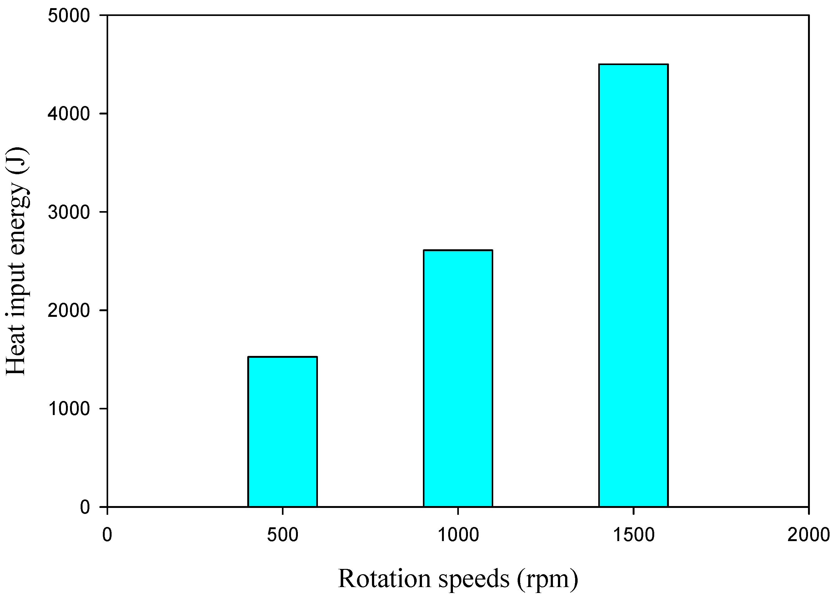
A previous work [57] indicated that FSSW variables and their influence on introduced heat input in SZ significantly affect the joint quality and material flow. The generated heat input is the sum of the frictional heat input developed at the tool shoulder contact area and pin surrounding area, and it is directly governed by a number of parameters, including the rotation speed, tool geometry, dwell time, plunge depth, and the interface friction coefficient between the tool and the stirring material [56]. The heat input energies for producing the AA5052-H32 welded joints at a 2s dwell time and various tool rotation speeds of 500, 1000, and 1500 rpm were calculated using the Equations mentioned in the previous work [57], and the obtained results are plotted in Figure 5. During the FSSW, it can be shown that raising the rotational speed from 500 to 1500 rpm increases the heat input created from 1525 to 4500 J, respectively [58].
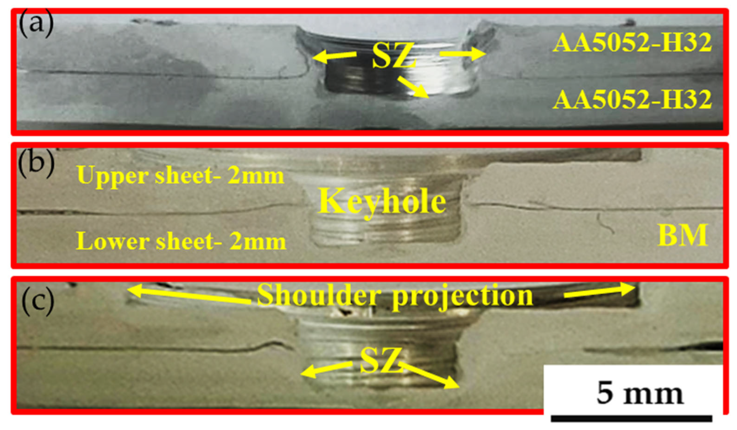
Figure 6 depicts the macrographs of the cross-sectional FSSWed AA5052-H32 specimens. It is noted that the suggested welding variables yield defect-free joints. In addition, at the chosen dwell time of 2 s, the SZ increases with the increase in rotation speed from 500 to 1000 rpm. At the applied rotation speeds of (a) 500, (b) 1000, and (c) 1500 rpm, the interface between the overlapped AA5052-H32 aluminum strips is spot welded as a result of severe plastic deformation and material movement around the rotating pin at a constant dwell time of 2 s, as shown in Figure 6. Furthermore, a small flash is noticed at a joint processed at the highest heat input (Figure 5) with a remarked increase in the shoulder projection depth (Figure 6c) [59]. The resulting FSSWed joints have a distinctive keyhole in the center of the spot weld, which expresses pin indentation when the welding process is completed. This keyhole accurately depicts the pin geometry and dimensions and a slight increase with the increase in rotation speed due to increasing the material softening around the rotating pin [38]. Previous research [19] has identified four different zones for the produced FSSWed joints: SZ, the thermomechanically affected zone (TMAZ), the heat-affected zone (HAZ), and base material (BM). These four regions are typical characteristics of the FSSW cross-sectional specimens.

3.3. Grain Structure

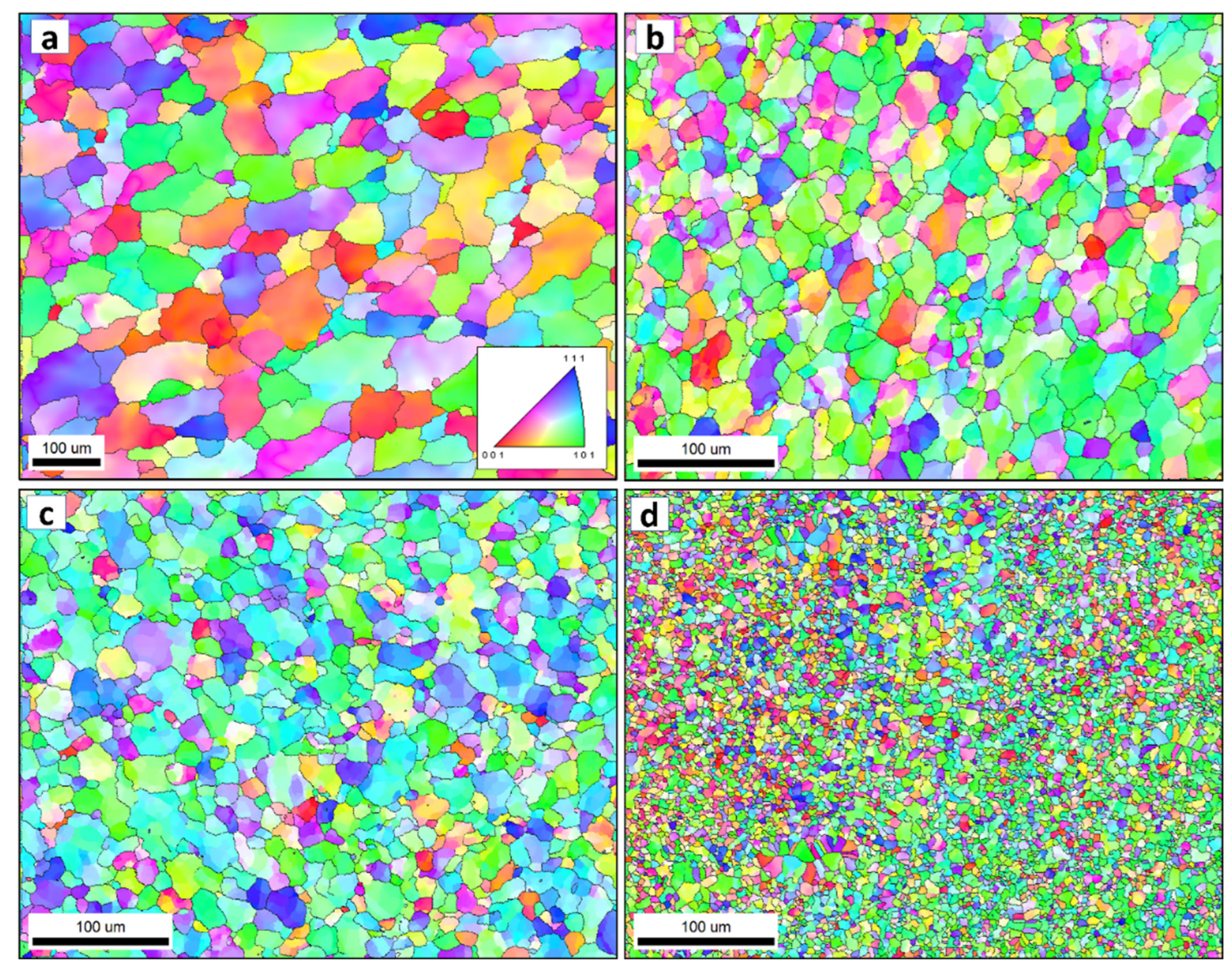
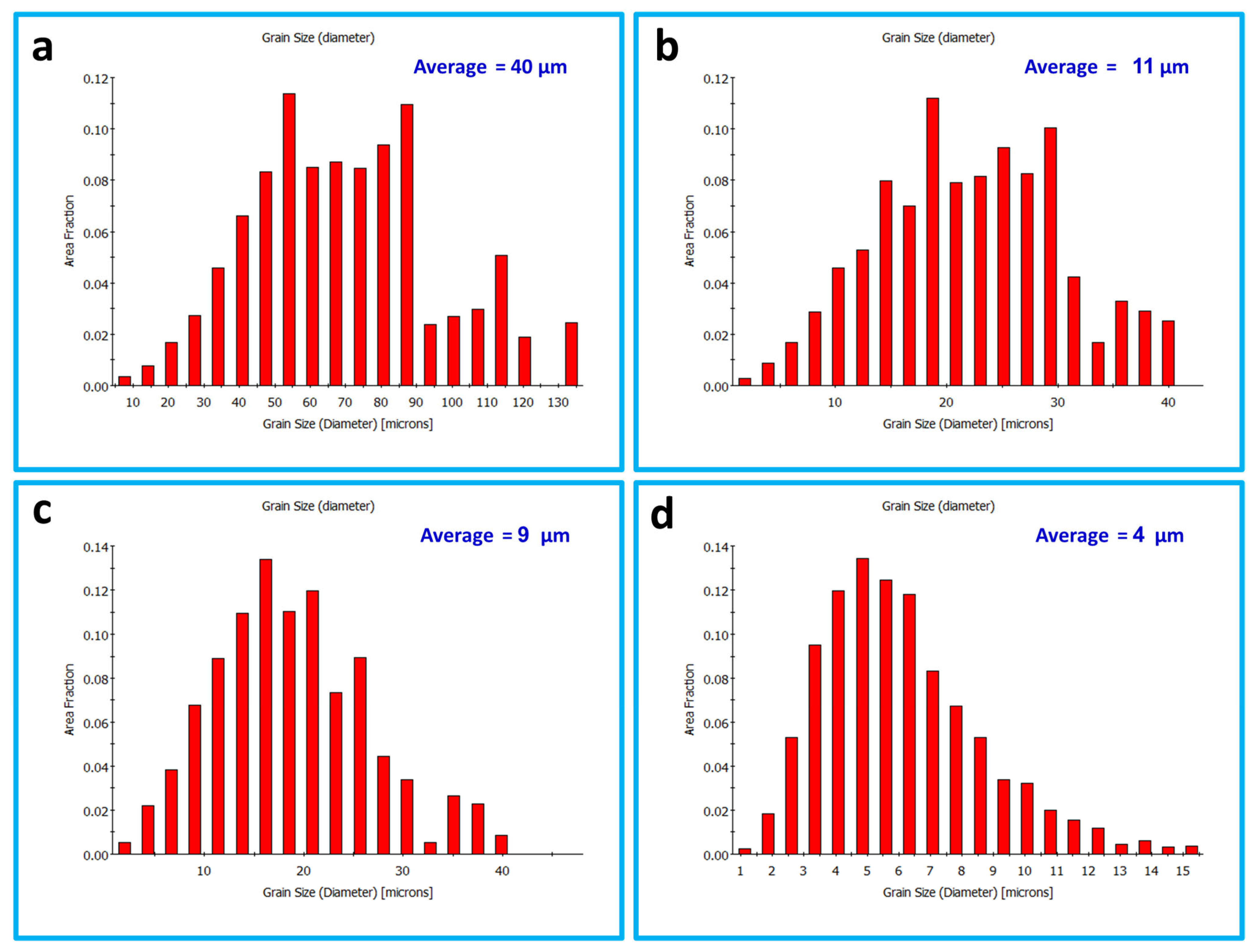
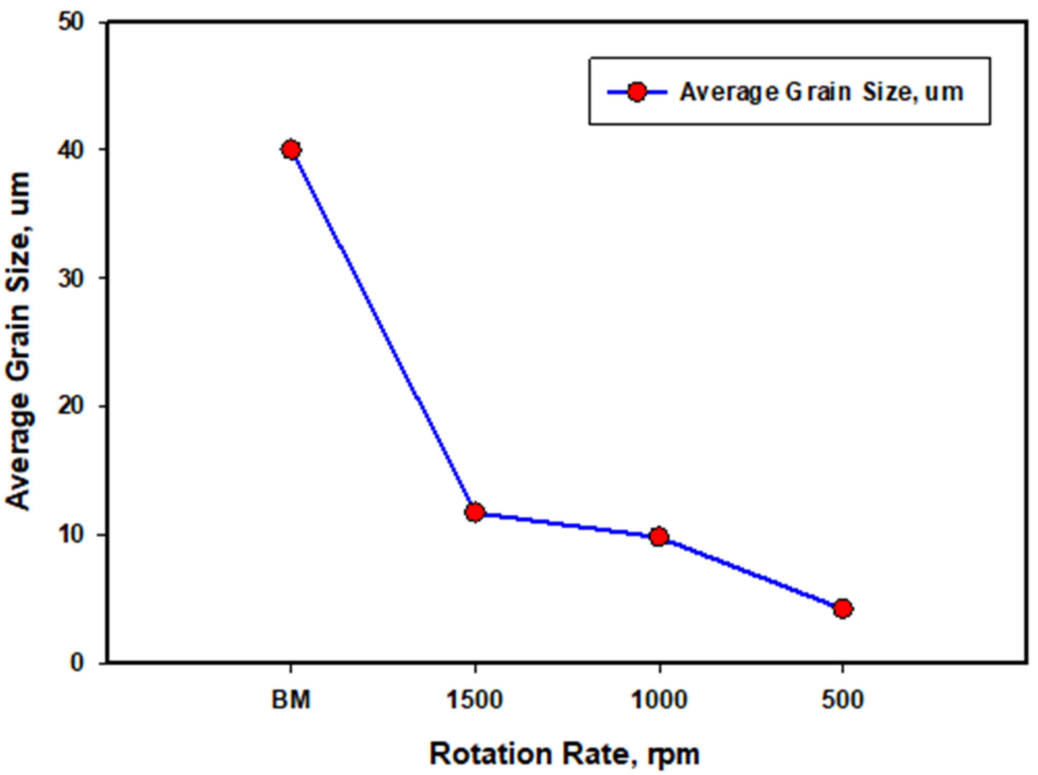
Figure 7 shows the inverse pole figure coloring (IPF) maps for the BM in (a) and the SZ of the FSSWed AA5052 at a constant dwell time of 2 s and different tool rotation rates of (b) 1500, (c) 1000 and (d) 500 rpm with the high angle boundaries greater than 15° of misorientation in superimposed black lines. The IPF map presented in Figure 7a for the BM indicates the coarse grain structure with mixed grain orientation. After FSSW, this coarse grain structure is dynamically recrystallized into an equiaxed grain structure with smaller grain sizes caused by the high strain and high temperature experienced due to the severe friction between the tool and the material. It can be observed that the microstructure becomes finer when reducing the tool rotation rate from 1500 rpm (Figure 7b) to 1000 rpm (Figure 7c) and further to 500 rpm (Figure 7d). In terms of orientation, the maps are dominated by the <101> green orientation. It should be mentioned here that these are the raw EBSD data without rotation. It is known that the deformation reference frame during FSW/FSSW is not fixed and moves in a radial path with the tool rotation, which requires rotation of the EBSD data to align the deformation reference frame with the shear reference frame [60]. Figure 8a–c shows the IFP maps after applying the required data rotation, mainly around the normal direction (ND). Now, it can be observed that the maps are dominated mainly by the <111> blue orientation, which implies the alignment of the <111> direction with the normal direction. The grain size distribution histograms for the BM and the FSSWed materials are presented in Figure 9. The BM grain size ranges from about 5 µm up to 130 µm with an average of about 40 µm. Significant grain size reduction can be noted after FSSW, where the grain size in the joint produced at 1500 rpm ranges from about 1 µm to 40 µm with an average of 11 µm that has been reduced to an average of 9 µm after decreasing the tool rotation to 1000 rpm. However, more notable grain size reduction can be noted after reducing the tool rotation to 500 rpm, where the grain size ranges from 1 µm to 15 µm with an average of about 4 µm. Figure 10 shows the average grain size against the tool rotation rate. This grain refinement caused by reducing the FSSW tool rotation rate is mainly due to the reduction in the heat generated during the process. It was found (Section 3.2) that the reduction in the FSSW tool rotation from 1500 rpm to 500 rpm reduced the heat input from 4500 to 1525 J. This reduction in the heat input allows the exposure of the weld zone to a lower thermal cycle profile during and after FSSW [61].
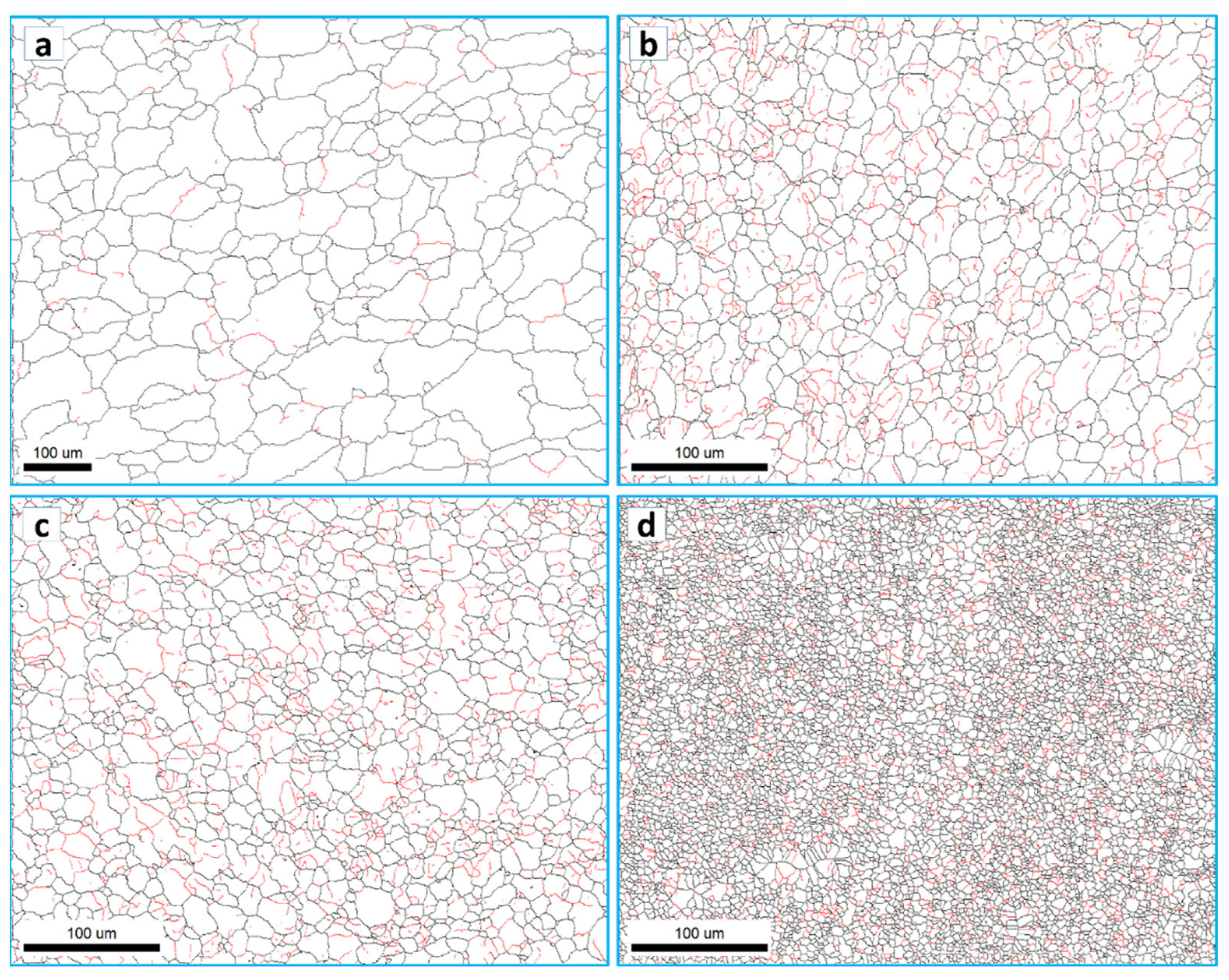
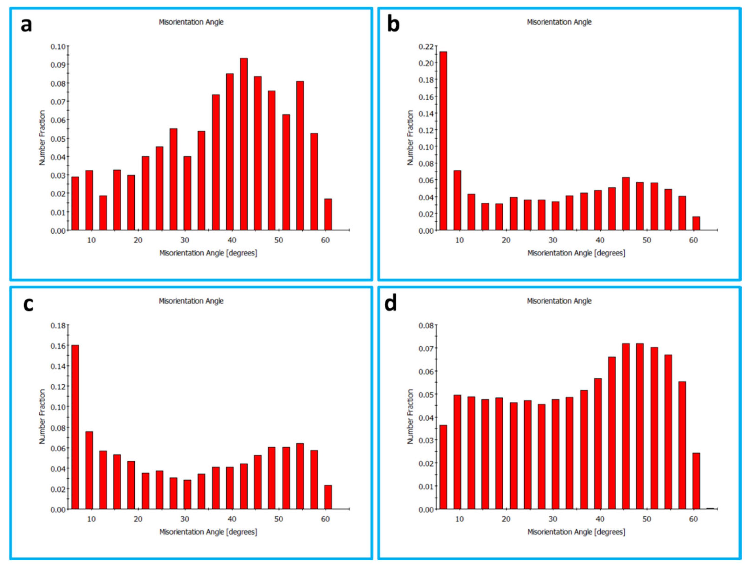
The grain boundary maps are presented in Figure 11 for the BM (a) and the FSSWed joints produced at different tool rotation speeds of 1500 (b), 1000 (c), and 500 (d) with the high-angle boundaries (HABs) >15° shown in black lines and 15° > low angle boundaries (LABs) > 5° shown in red lines. HABs mainly dominate the BM GB map with only a slight fraction of LABs, whereas the GB maps of the FSSWed material consist of HAB and a high fraction of LABs. This microstructural feature indicates that the severe plastic deformation at high temperatures is associated with continuous dynamic recrystallization, forming a new grain structure [62]. The cooling afterward preserves a high fraction of substructures. The misorientation angle histograms presented in Figure 12a–d compare the BM and FSSWed materials, which clearly show the dominance of the HABs in the BM and the high fraction LABs in the FSSWed material, especially in the histograms for the joints produced at 1500 and 1000 rpm. In contrast, the joint produced at 500 rpm dominates the HABs again due to the extremely fine grain structure formed.

3.4. Crystallographic Texture

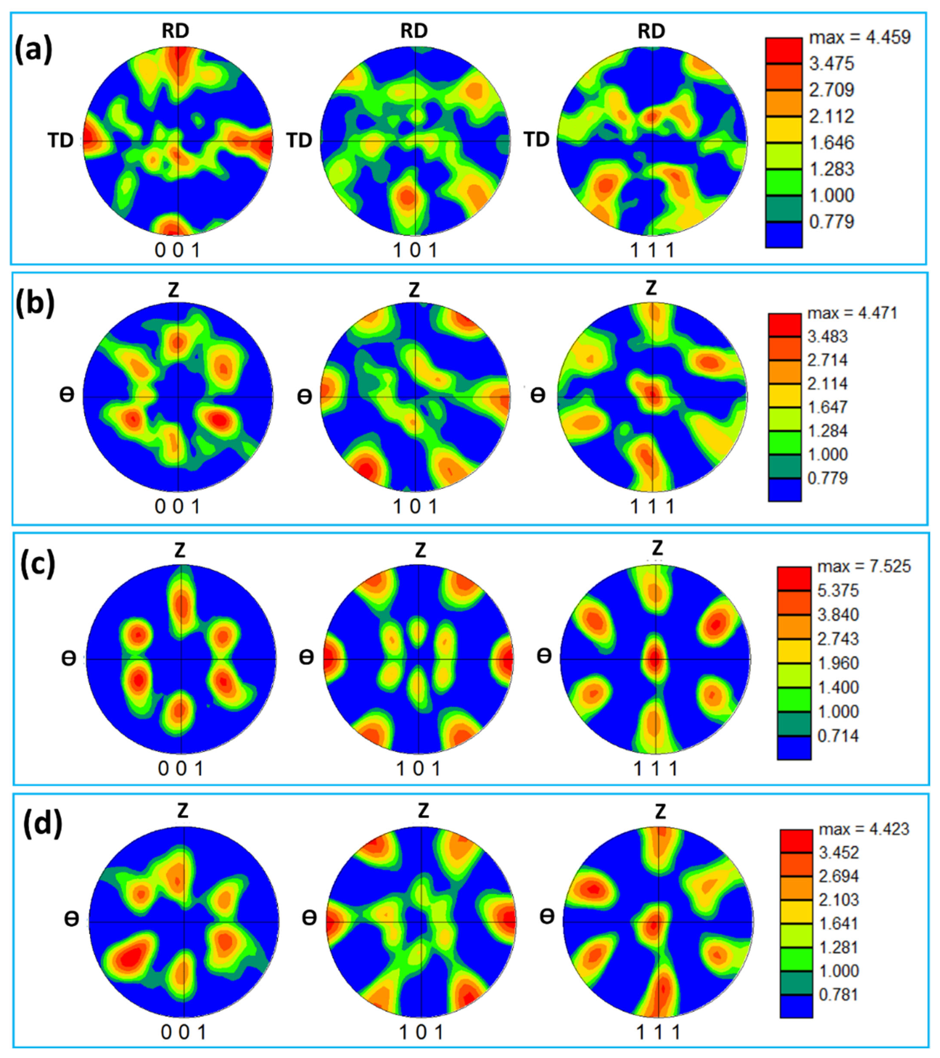
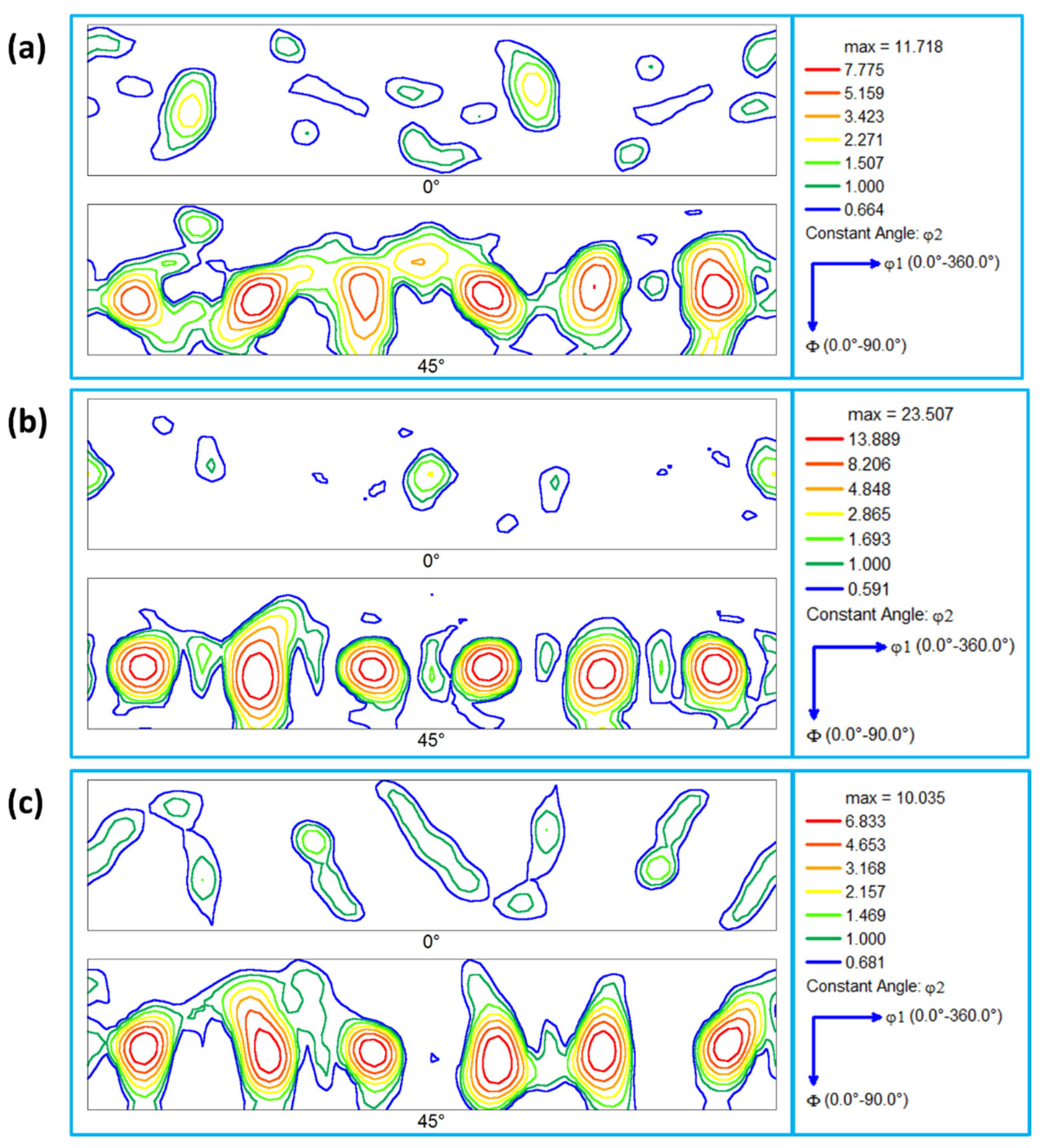
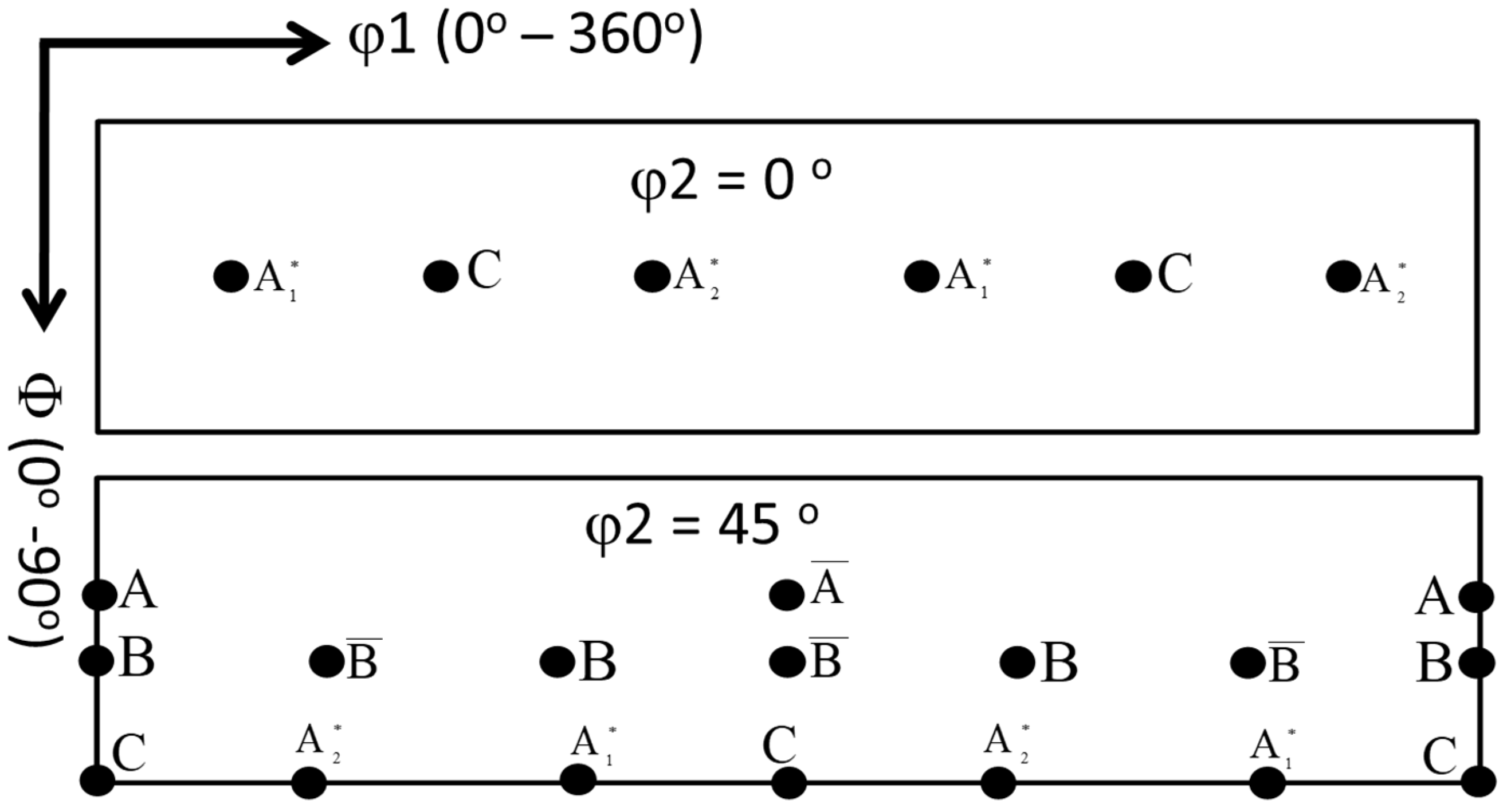
The deformation of aluminum during FSW/FSSW is mainly dominated by simple shear deformation that mainly results in a simple shear texture due to the alignment of the {111} slip plane with the shear plane and/or alignment of the <110> slip direction with the shear direction [63]. Table 1 shows the different types of texture fibers that can develop upon shear deformation depending on the extent of strain experienced. It can be observed that the rotated cube texture of the BM (Figure 13a) has completely changed after FSSW in the NG zone into the simple shear texture with the B/-B texture components existing at their ideal position in the pole figures, as shown in Figure 13b–d. It can be observed that the texture intensity for the joint produced at 1500 rpm (Figure 13b) is about 5 times random, that it increased to about 8 times random for the joint produced at 1000 rpm (Figure 13c), and that the texture intensity reduced again to about 4 times random for the joint produced at 500rpm. At the high rotation rate, the heat input is maximum and the temperature at the weld zone is expected to be high, which can accelerate the restoration mechanisms, mainly recovery, and recrystallization. It should be mentioned here that the obtained EBSD data was rotated to align the deformation reference frame (TD: transverse direction, WD: welding direction, and ND: normal direction) with the shear reference frame (θ, z, and r). The rotations are mainly about the ND and TD. The reason for these rotations has been reported by previous studies on the texture analysis of friction stir welded aluminum [60,64]. Fonda and Bingert [64] rotated the pole figures 7° about the WD, 7° about the TD, and 10° about the ND to align them with the ideal shear deformation reference frame. Ahmed et al. [60] reported a systematic rotation in the texture across the whole SZ in their investigation of texture across the SZ in friction stir welded AA6082 of 30 mm thickness. Thus, two rotations are required to analyze the texture components relative to the shear reference frame across the whole SZ: rotation about the ND to take into account the shear reference frame rotation about the ND and rotation about the TD to take into account the shear reference frame tilt due to the tapering of the probe [60]. In this work, the pole figures have been rotated about the ND and TD to obtain the texture components at their ideal positions. The orientation distribution function (ODF) was used to create sections at φ2 = 45° and φ2 = 0° for the FSSWed samples at different rotation rates of 1500 rpm (Figure 14a), 1000 rpm (Figure 14b), and 500 rpm (Figure 14c). From these ODF sections, the dominance of the B/-B texture components can be observed. In addition, the joint produced showed the highest texture intensity. However, the B/-B texture components are still slightly shifted about 22.5° from their ideal position when compared to the ideal texture components positions presented schematically in Figure 15 for ODF sections at φ2 = 45° and φ2 = 0°. Also, Table 2 gives the partial fibers and ideal components of simple shear texture in fcc metal.

3.5. Hardness Evaluation

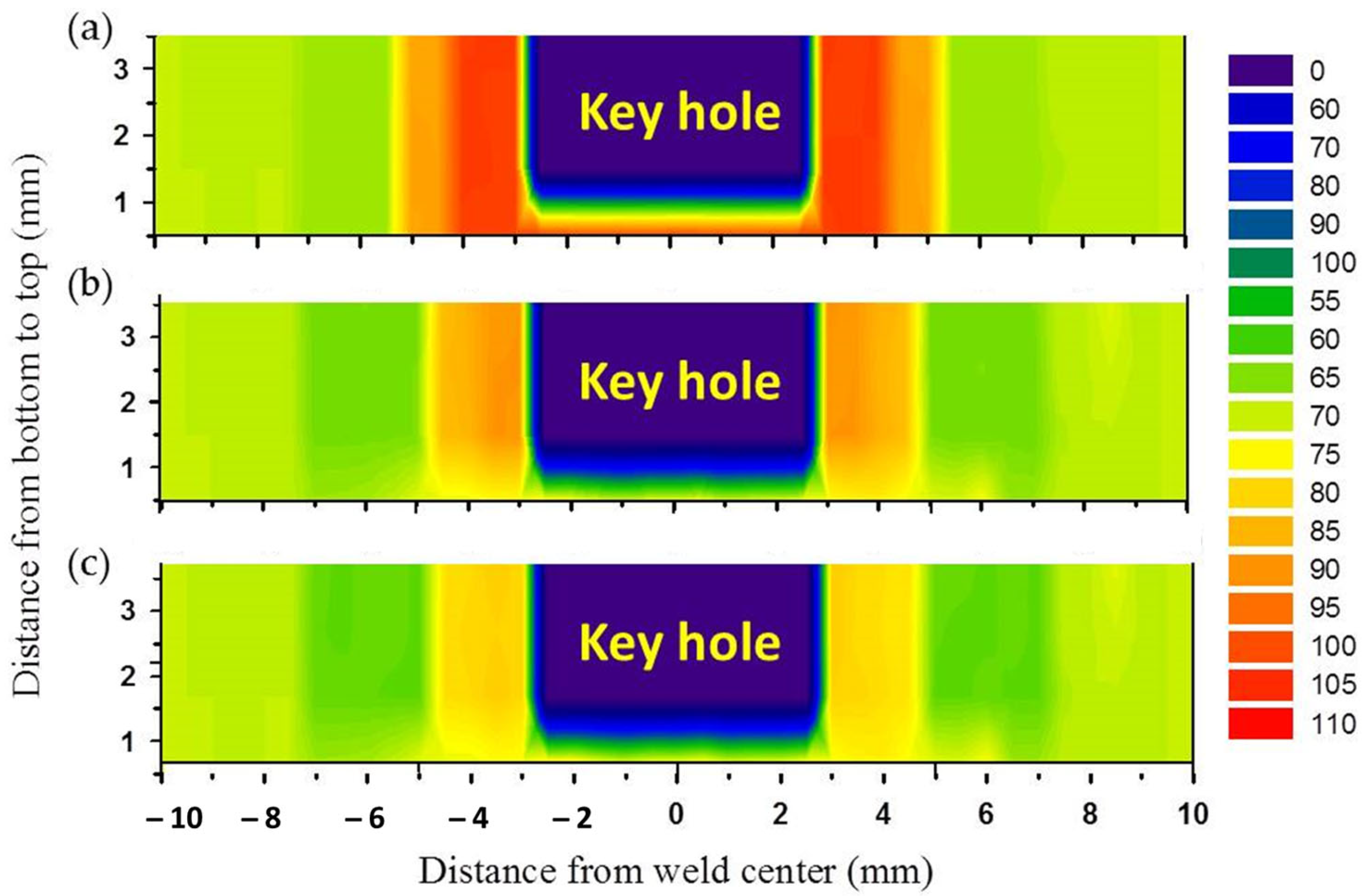
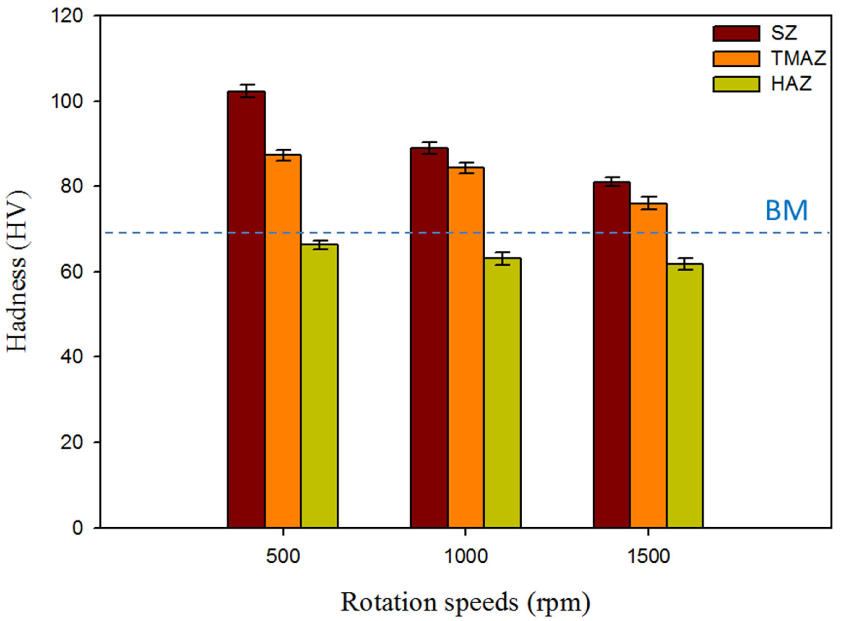
The hardness of the produced AA5052-H32 FSSW lap joints was evaluated using transverse cross-sections. The measurements were displayed on a contour map with different colors representing varying hardness levels. Figure 16 shows the hardness contour maps of the FSSWed specimens processed at a 2 s dwell time and various tool rotation speeds of 500, 1000, and 1500 rpm. The cylindrical pin achieved a symmetrical hardness distribution with regard to the center line of the FSSW keyhole for all the applied tool rotation speeds of 500, 1000, and 1500 rpm, as given in Figure 16a–c, respectively. Furthermore, the hardness values of the welded regions, SZ, and TMAZ in the AA5052-H32 FSSWed joints were significantly higher at all the used rotation speeds than the BM. However, depending on the thermal exposure cycle (total heat input), the hardness of the HAZ is somewhat less than that of the AA5052-H32 BM, as shown in Figure 16 and Figure 17. These results agree with those previously reported by other researchers [27,29]. Tiwan et al. [27] observed that the SZ in the FSSWed AA5052-H112 Al alloy joints had higher hardness than the TMAZ and HAZ. They attributed this improvement in hardness to the grain refining process owing to dynamic recrystallization. Dynamic recrystallization occurs when crystalline materials are plastically deformed at high temperatures [66]. Likewise, Kwon et al. [66] ascribed an enhanced hardness of the SZ in the FSSW A5052-O joints over its BM to grain refining. In the current work, the minimal hardness values found in the HAZ for all the AA5052-H32 FSSW joints can be related to the grain structure and strain hardening release. However, the increased hardness of the SZ was mostly due to the development of dynamically recrystallized equiaxed fine grains and the potential intermetallic fragmentation process that occurred during the stirring action [29]. As seen in Figure 17, the TMAZ has a lower hardness than the SZ but a higher hardness than the HAZ. It can be concluded that the high dislocation density generated by extreme plastic deformation during the welding process promotes the increased hardness of the TMAZ above the HAZ. At a constant dwell time of 2 s, the FSSW joints fabricated at 500 rpm show the highest average hardness values of 102.3 ± 3 in the SZ compared to the BM (69 ± 2) and the other joints produced at 1000 rpm (89.2 ± 2) and 1500 rpm (81.3 ± 2), as shown in Figure 17. This decrease in hardness in the SZ with increasing rotation speed is ascribed to the raised introduced heat input.

3.6. Tensile Test Results and Evaluation of Fracture Surfaces

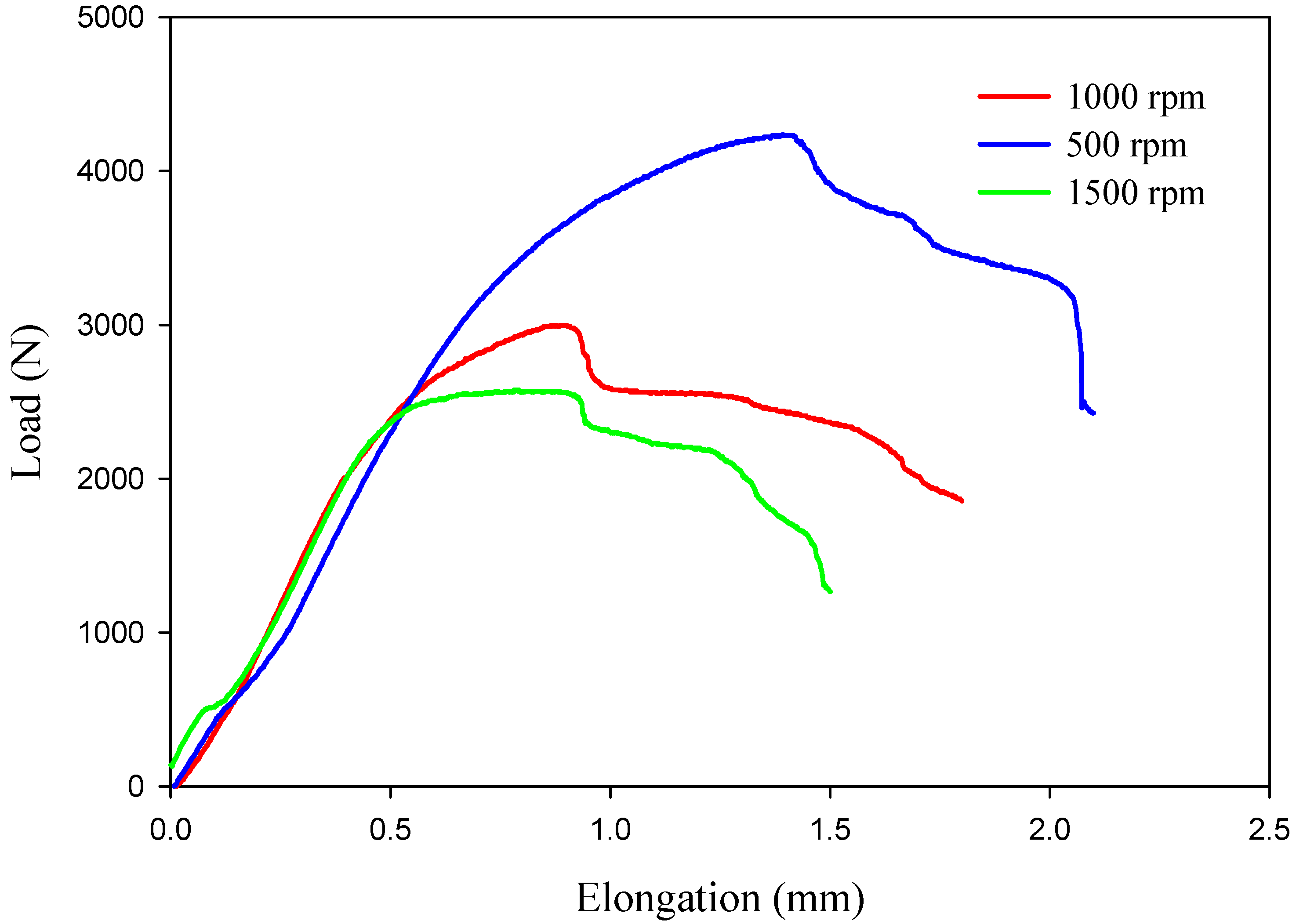
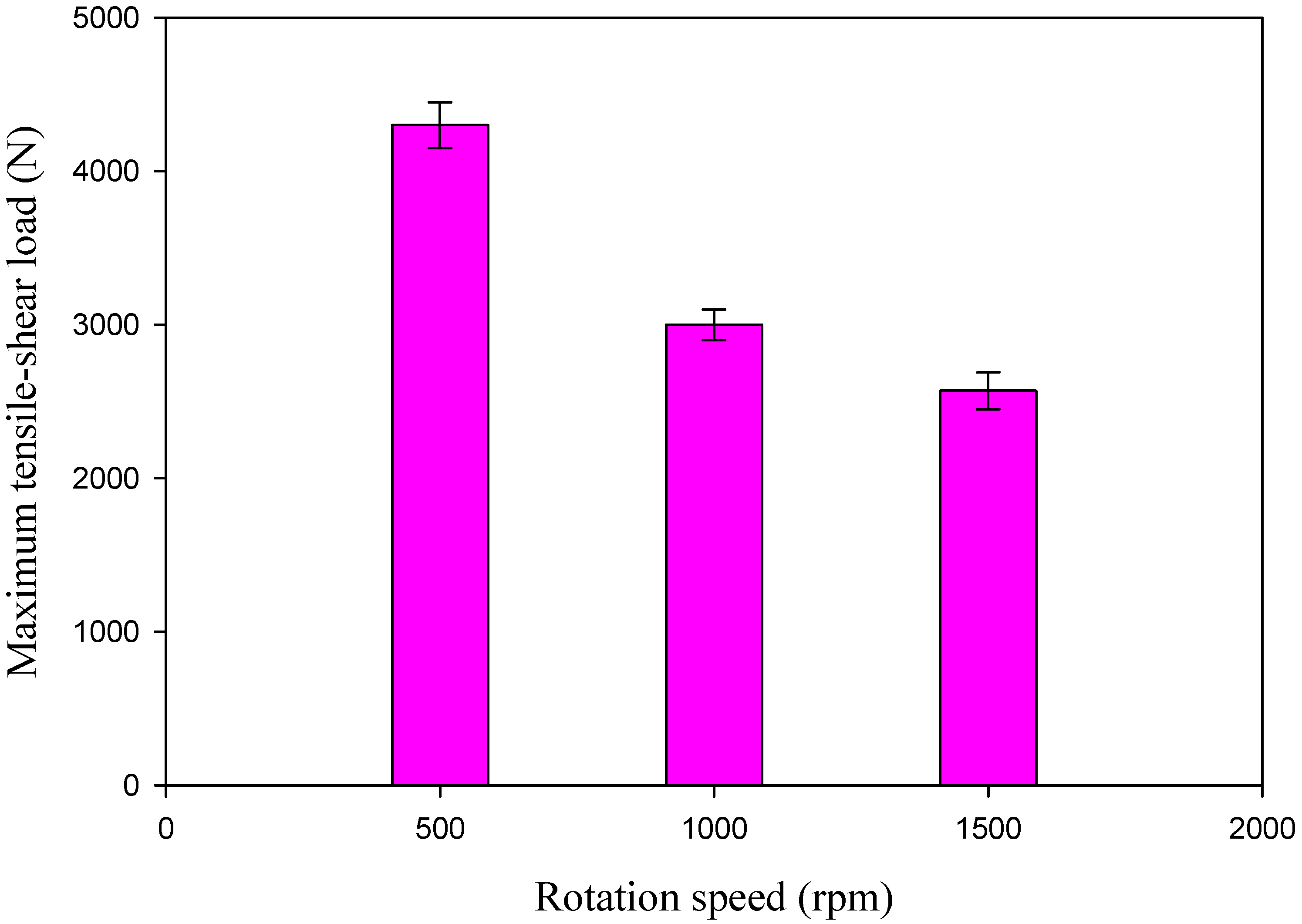
When designing new types of automobiles, aircraft, and ships, engineers must consider the efficiency of spot-welded connections. Thus, the FSSWed AA5052-H32 joints were subjected to a tensile shear test to determine the maximum load-carrying capacity of each joint and to optimize the processing parameters. It was found that the FSSW process parameters influence the maximum tensile shear value of the spot-welded connection [67,68]. Figure 18 shows load elongation curves for the tensile–shear test results of the spot-welded specimens manufactured at different rotation speeds of 500, 1000, and 1500 rpm and a 2 s dwell time. Figure 19 depicts the maximum value of the tensile–shear load of the AA50520-H32 FSSW specimens against the applied different rotation speeds. It can be noted that the FSSW processing parameters (2 s dwell time and 500 rpm) give the highest tensile–shear load of 4330 ± 120 N when compared to the tensile–shear loads of the processed joints at 1000 rpm (3000 ± 100 N) and 1500 rpm. (2569 ± 90 N), as shown in Figure 18 and Figure 19. This increase in performance in terms of the maximum load carrying capacity of the joint processed at 500 rpm may be attributed to the largest welded zone [35] and the highest hardness value of the SZ compared to the other joints. In addition, higher rotation speeds of 1000 and 1500 rpm (higher heat input energy) achieve sufficient mixing between the two welded aluminum strips, and the extra heat may cause softening in the welded area and increase the HAZ area, resulting in a lower joint strength than that processed at 500 rpm, as shown in Figure 10. Overall, it can be remarked that the tensile results confirmed the hardness results for all the produced joints.
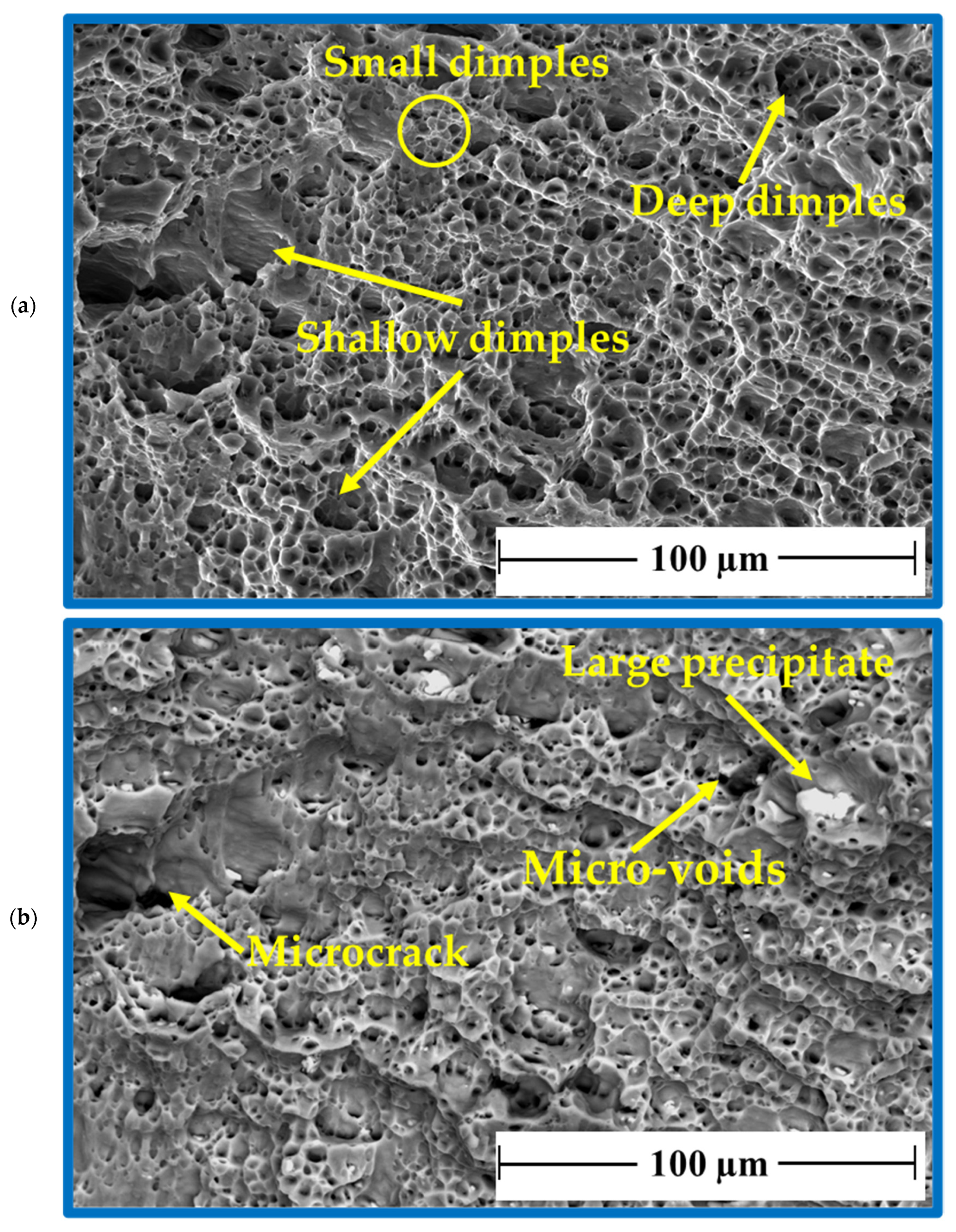
After tensile testing, the fracture surface of AA 5052-H32 BM was examined using two SEM detectors, i.e., the Everhart–Thornley Detector (ETD) and a low K-Volt High-Contract Detector (vCD), to study the fracture surface features, as shown in Figure 20a,b, respectively. There are two fracture modes: mainly ductile and partly brittle. The AA505-H32 aluminum alloy matrix showed a ductile fracture in different dimples with shapes and sizes (Figure 20a), whereas the brittle fracture mode was given by the large precipitates of Al3Fe and Mg2Si [69]. Furthermore, micro-cracks and micro-voids are also seen as a result of the precipitate’s pull-out mechanism from the fracture surface (Figure 20b).
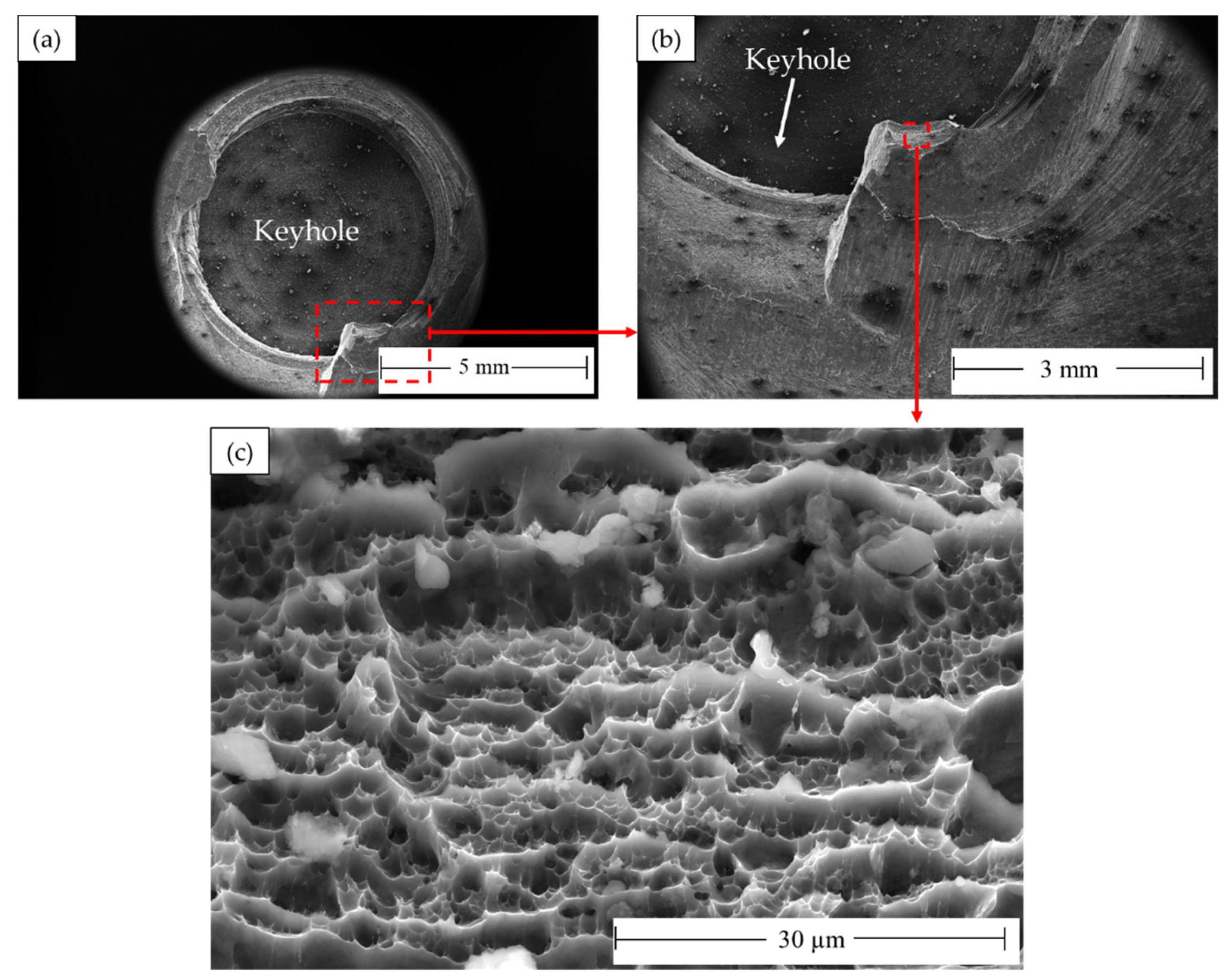
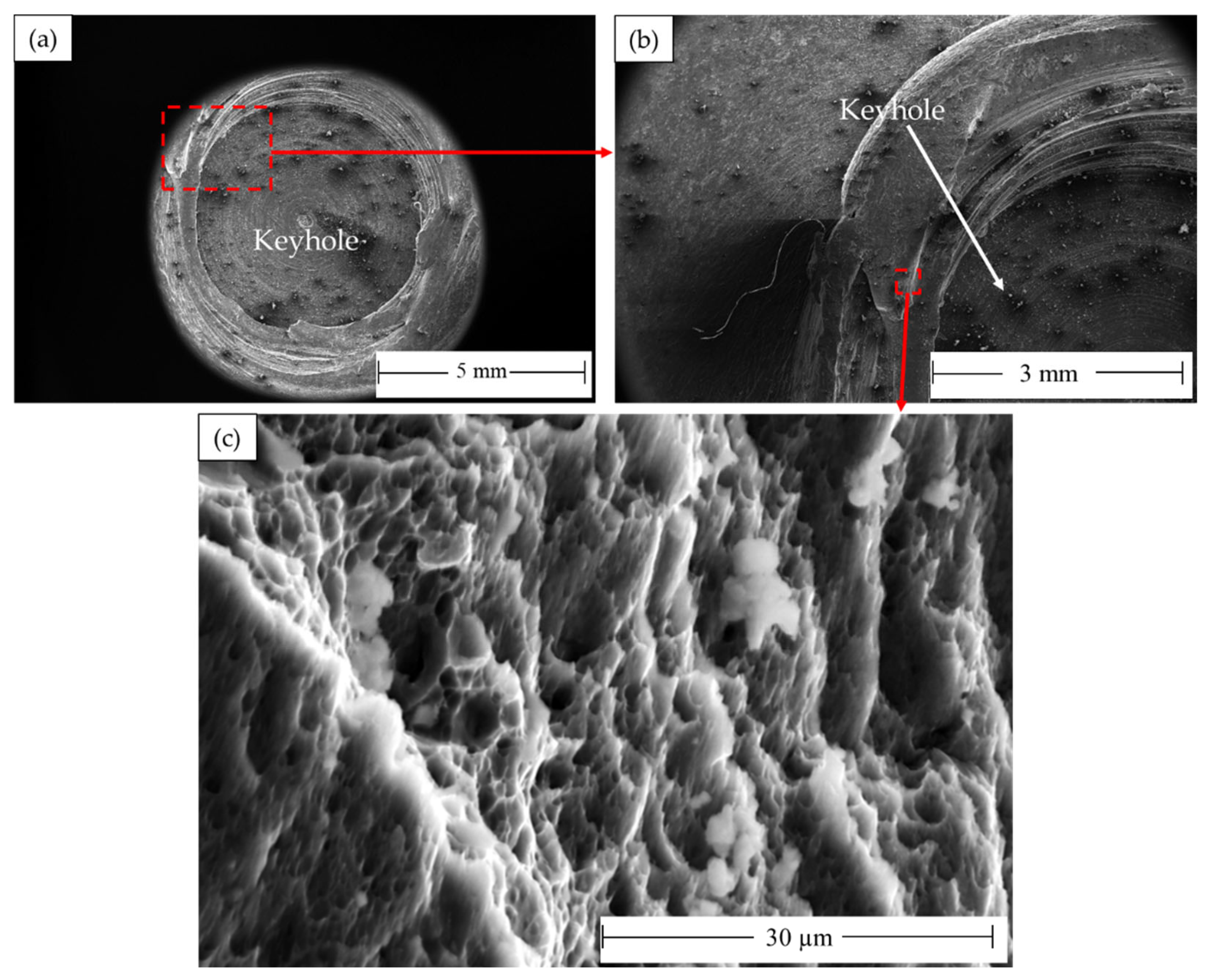
The processed AA 5052-H32 lap joints are detached during the tensile test. Figure 21 shows photo images of the failed joints after tensile testing. As can be observed, all the produced joints start to fracture at the edge of the SZ and develop along the depression in the upper joint strip. After the joint was separated into two parts, the upper sheet in the SZ was left in the lower sheet to form a button shape. Figure 22, Figure 23 and Figure 24 show fracture surface SEM images of the separated lower sheets after the tensile–shear test for the 5052-H32 FSSW specimens processed at different rotation speeds of 500 rpm (Figure 22a–c), 1000 rpm (Figure 23a–c), and 1500 rpm (Figure 24a–c) and a 2 s dwell time. The tensile–shear mechanism caused the failure in the three FSSW joints. Microcracks start at the partly bonded area at the tip of the hook and preferentially propagate horizontally at the weld joint interface during tensile–shear testing, shearing the SZ and leading to failure. Compared to the AA5052-H32 BM, the fracture surfaces on the three welds at the lower sheets show typical ductile characteristics in the form of small equiaxed dimples, indicating grain refinement due to dynamic recrystallization through the SZ during the welding process.

4. Conclusions

In this work, 2 mm thick AA5052-H32 strips were FSSWed at various tool rotation speeds of 1500, 1000, and 500 rpm while the dwell time was fixed at a constant value of 2 s. The macro- and microstructure features, crystallographic texture, and mechanical properties of produced welds were assessed, and the following conclusions were drawn:
  • In comparison to the AA5052-H32 BM, all the FSSWed AA5052-H32 lap joints showed an improvement in the hardness of the SZ and TMAZ. Moreover, the SZ displayed higher values of hardness than those observed for the TMAZ and HAZ. In addition, the hardness of the weld zone decreases with increasing rotation speed from 500 to 1000 rpm.
  • Compared to the AA5052-H32 BM grain size (40 µm), there was significant grain refining in the SZ of the produced FSSW joints. For the FSSWed joints processed at 1500, 1000, and 500 rpm, the grain size values in the stir zones were 11, 9, and 4 µm, respectively. The grain size decreased with decreasing heat input.
  • The texture is mainly dominated by B/-B simple shear texture components with little effect of the rotation rate either on the texture components or the intensity of the texture.
  • The spot-welded joint produced at 500 rpm and 2 s showed the highest SZ hardness of 102.3 ± 3 HV0.5 and tensile–shear load value of 4330 ± 30 N among the produced joints.
  • When compared to the AA5052-H32 BM, the fracture surfaces on the three welds at the lower sheets showed typical ductile characteristics in the form of small equiaxed dimples, indicating grain refinement due to dynamic recrystallization through the SZ during the FSSW process.
  • Finally, this work opens a fruitful field for researchers to work towards manufacturing spot welding joints at a low tool rotation speed equal to or less than 500 rpm and a short time of 2 s for different aluminum alloys, which represents a significant industrial goal to reduce energy use and production time.

Author Contributions

Conceptualization, M.M.Z.A. and M.M.E.-S.S.; methodology, M.M.Z.A., I.A., and M.M.E.-S.S.; software, I.A. and A.A.E.-A.; validation, M.M.Z.A., A.A.E.-A., and M.M.E.-S.S.; formal analysis, M.M.Z.A. and M.M.E.-S.S.; investigation, M.M.Z.A. and M.M.E.-S.S.; resources, I.A. and A.A.E.-A.; data curation, M.M.Z.A., I.A. and M.M.E.-S.S.; writing—original draft preparation, M.M.E.-S.S., A.A.E.-A. and M.M.Z.A.; writing—review and editing, M.M.Z.A., A.A.E.-A. and I.A.; visualization, A.A.E.-A. and I.A.; supervision, M.M.Z.A. and M.M.E.-S.S.; project administration, M.M.Z.A. and M.M.E.-S.S.; funding acquisition, M.M.Z.A., I.A., A.A.E.-A. and M.M.E.-S.S. All authors have read and agreed to the published version of the manuscript.

Funding

This study was funded by the Deputyship for Research & Innovation, Ministry of Education in Saudi Arabia under project number (IF2-PSAU-2022/01/20939).

Institutional Review Board Statement

Not applicable.

Informed Consent Statement

Not applicable.

Data Availability Statement

Data will be available upon request to the corresponding author.

Acknowledgments

The authors extend their appreciation to the Deputyship for Research & Innovation, Ministry of Education in Saudi Arabia for funding this research work through project number (IF2-PSAU-2022/01/20939).

Conflicts of Interest

The authors declare no conflict of interest.

References

  1. Benedyk, J.C. Aluminum Alloys for Lightweight Automotive Structures; Woodhead Publishing Limited: Soston, UK, 2010; ISBN 9781845694630. [Google Scholar]
  2. El-Sayed Seleman, M.M.; Ataya, S.; Ahmed, M.M.Z.; Hassan, A.M.M.; Latief, F.H.; Hajlaoui, K.; El-Nikhaily, A.E.; Habba, M.I.A. The Additive Manufacturing of Aluminum Matrix Nano Al2O3 Composites Produced via Friction Stir Deposition Using Different Initial Material Conditions. Materials 2022, 15, 2926. [Google Scholar] [CrossRef] [PubMed]
  3. Mohamed, A.M.A.; Hasan, H.; Seleman, M.M.E.-S.; Ahmed, E.; Saleh, S.M.; El-Maghraby, R.M. Performance of Sprayed PVDF-Al2O3 Composite Coating for Industrial and Civil Applications. Materials 2021, 14, 6358. [Google Scholar] [CrossRef] [PubMed]
  4. Yamada, H.; Kami, T.; Mori, R.; Kudo, T.; Okada, M. Strain Rate Dependence of Material Strength in Aa5xxx Series Aluminum Alloys and Evaluation of Their Constitutive Equation. Metals 2018, 8, 576. [Google Scholar] [CrossRef]
  5. Li, Y.; Li, L.; Nie, J.; Cao, Y.; Zhao, Y.; Zhub, Y. Microstructural Evolution and Mechanical Properties of a 5052 Al Alloy with Gradient Structures. J. Mater. Res. 2017, 32, 4443–4451. [Google Scholar] [CrossRef]
  6. Ozturk, F.; Toros, S.; Kilic, S. Evaluation of Tensile Properties of 5052 Type Aluminum-Magnesium Alloy at Warm Temperatures. Arch. Mater. Sci. Eng. 2008, 34, 95–98. [Google Scholar]
  7. Sen, R.; Choudhury, S.P.; Kumar, R.; Panda, A. A Comprehensive Review on the Feasibility Study of Metal Inert Gas Welding. Mater. Today Proc. 2018, 5, 17792–17801. [Google Scholar] [CrossRef]
  8. Ye, Z.; Huang, J.; Gao, W.; Zhang, Y.; Cheng, Z.; Chen, S.; Yang, J. Microstructure and Mechanical Properties of 5052 Aluminum Alloy/Mild Steel Butt Joint Achieved by MIG-TIG Double-Sided Arc Welding-Brazing. Mater. Des. 2017, 123, 69–79. [Google Scholar] [CrossRef]
  9. Shanavas, S.; Raja Dhas, J.E. Weldability of AA 5052 H32 Aluminium Alloy by TIG Welding and FSW—A Comparative Study. In Proceedings of the 1st International Conference on Recent Advances in Aerospace Engineering (ICRAAE-2017), Coimbatore, India, 3–4 March 2017; Volume 247. [Google Scholar] [CrossRef]
  10. Sarmast, A.; Serajzadeh, S. The Influence of Welding Polarity on Mechanical Properties, Microstructure and Residual Stresses of Gas Tungsten Arc Welded AA5052. Int. J. Adv. Manuf. Technol. 2019, 105, 3397–3409. [Google Scholar] [CrossRef]
  11. Sekhar, S.R.; Chittaranjandas, V.; Govardhan, D.; Karthikeyan, R. Effect of Tool Rotational Speed on Friction Stir Spot Welded AA5052-H38 Aluminum Alloy. Mater. Today Proc. 2018, 5, 5536–5543. [Google Scholar] [CrossRef]
  12. Luo, Z.; Ao, S.; Chao, Y.J.; Cui, X.; Li, Y.; Lin, Y. Application of Pre-Heating to Improve the Consistency and Quality in AA5052 Resistance Spot Welding. J. Mater. Eng. Perform. 2015, 24, 3881–3891. [Google Scholar] [CrossRef]
  13. Xiao, R.; Zhang, X. Problems and Issues in Laser Beam Welding of Aluminum-Lithium Alloys. J. Manuf. Process. 2014, 16, 166–175. [Google Scholar] [CrossRef]
  14. Doshi, S.J.; Gohil, A.V.; Mehta, N.; Vaghasiya, S. Challenges in Fusion Welding of Al Alloy for Body in White. Mater. Today Proc. 2018, 5, 6370–6375. [Google Scholar] [CrossRef]
  15. Mei, Y.; Liu, Y.; Liu, C.; Li, C.; Yu, L.; Guo, Q.; Li, H. Effect of Base Metal and Welding Speed on Fusion Zone Microstructure and HAZ Hot-Cracking of Electron-Beam Welded Inconel 718. Mater. Des. 2016, 89, 964–977. [Google Scholar] [CrossRef]
  16. Ahmed, M.M.Z.; El-Sayed Seleman, M.M.; Fydrych, D.; Çam, G. Friction Stir Welding of Aluminum in the Aerospace Industry: The Current Progress and State-of-the-Art Review. Materials 2023, 16, 2971. [Google Scholar] [CrossRef]
  17. Ahmed, M.M.Z.; El-Sayed Seleman, M.M.; Eid, R.G.; Zawrah, M.F. Production of AA1050/Silica Fume Com-posite by Bobbin Tool-Friction Stir Processing: Microstructure, Composition and Mechanical Properties. CIRP J. Manuf. Sci. Technol. 2022, 38, 801–812. [Google Scholar] [CrossRef]
  18. Ahmed, M.M.Z.; El-Sayed Seleman, M.M.; Ahmed, E.; Reyad, H.A.; Alsaleh, N.A.; Albaijan, I. A Novel Friction Stir Deposition Technique to Refill Keyhole of Friction Stir Spot Welded AA6082-T6 Dissimilar Joints of Different Sheet Thicknesses. Materials 2022, 15, 6799. [Google Scholar] [CrossRef]
  19. Çam, G.; Javaheri, V.; Heidarzadeh, A. Advances in FSW and FSSW of Dissimilar Al-Alloy Plates. J. Adhes Sci. Technol. 2023, 37, 162–194. [Google Scholar] [CrossRef]
  20. Bozkurt, Y.; Salman, S.; Çam, G. Effect of Welding Parameters on Lap Shear Tensile Properties of Dissimilar Friction Stir Spot Welded Aa 5754-H22/2024-T3 Joints. Sci. Technol. Weld. Join. 2013, 18, 337–345. [Google Scholar] [CrossRef]
  21. Venukumar, S.; Baby, B.; Muthukumaran, S.; Kailas, S.V. Microstructural and Mechanical Properties of Walking Friction Stir Spot Welded AA 6061-T6 Sheets. Procedia Mater. Sci. 2014, 6, 656–665. [Google Scholar] [CrossRef]
  22. Çam, G.; Ipekoğlu, G.; Tarık Serindağ, H. Effects of Use of Higher Strength Interlayer and External Cooling on Properties of Friction Stir Welded AA6061-T6 Joints. Sci. Technol. Weld. Join. 2014, 19, 715–720. [Google Scholar] [CrossRef]
  23. Freeney, T.A.; Sharma, S.R.; Mishra, R.S. Effect of Welding Parameters on Properties of 5052 Al Friction Stir Spot Welds. SAE Technol. Pap. 2006. [Google Scholar] [CrossRef]
  24. Tozaki, Y.; Uematsu, Y.; Tokaji, K. Effect of Tool Geometry on Microstructure and Static Strength in Friction Stir Spot Welded Aluminium Alloys. Int. J. Mach. Tools Manuf. 2007, 47, 2230–2236. [Google Scholar] [CrossRef]
  25. Arul, S.G.; Miller, S.F.; Kruger, G.H.; Pan, T.Y.; Mallick, P.K.; Shih, A.J. Experimental Study of Joint Performance in Spot Friction Welding of 6111-T4 Aluminium Alloy. Sci. Technol. Weld. Join. 2008, 13, 629–637. [Google Scholar] [CrossRef]
  26. Rana, P.K.; Narayanan, R.G.; Kailas, S.V. Effect of Rotational Speed on Friction Stir Spot Welding of AA5052-H32/HDPE/AA5052-H32 Sandwich Sheets. J. Mater. Process. Technol. 2018, 252, 511–523. [Google Scholar] [CrossRef]
  27. Tiwan; Ilman, M.N. Kusmono Microstructure and Mechanical Properties of Friction Stir Spot Welded AA5052-H112 Aluminum Alloy. Heliyon 2021, 7, e06009. [Google Scholar] [CrossRef] [PubMed]
  28. Merzoug, M.; Mazari, M.; Berrahal, L.; Imad, A. Parametric Studies of the Process of Friction Spot Stir Welding of Aluminium 6060-T5 Alloys. Mater. Des. 2010, 31, 3023–3028. [Google Scholar] [CrossRef]
  29. Rana, P.K.; Narayanan, R.G.; Kailas, S.V. Friction Stir Spot Welding of AA5052-H32/HDPE/AA5052-H32 Sandwich Sheets at Varying Plunge Speeds. Thin-Walled Struct. 2019, 138, 415–429. [Google Scholar] [CrossRef]
  30. Zhang, Z.; Yang, X.; Zhang, J.; Zhou, G.; Xu, X.; Zou, B. Effect of Welding Parameters on Microstructure and Mechanical Properties of Friction Stir Spot Welded 5052 Aluminum Alloy. Mater. Des. 2011, 32, 4461–4470. [Google Scholar] [CrossRef]
  31. Lathabai, S.; Painter, M.J.; Cantin, G.M.D.; Tyagi, V.K. Friction Spot Joining of an Extruded Al-Mg-Si Alloy. Scr. Mater. 2006, 55, 899–902. [Google Scholar] [CrossRef]
  32. Tran, V.X.; Pan, J.; Pan, T. Effects of Processing Time on Strengths and Failure Modes of Dissimilar Spot Friction Welds between Aluminum 5754-O and 7075-T6 Sheets. J. Mater. Process. Technol. 2009, 209, 3724–3739. [Google Scholar] [CrossRef]
  33. Mahmoud, T.S.; Khalifa, T.A. Microstructural and Mechanical Characteristics of Aluminum Alloy AA5754 Friction Stir Spot Welds. J. Mater. Eng. Perform. 2014, 23, 898–905. [Google Scholar] [CrossRef]
  34. D’Urso, G.; Giardini, C. Thermo-Mechanical Characterization of Friction Stir Spot Welded AA7050 Sheets by Means of Experimental and FEM Analyses. Materials 2016, 9, 689. [Google Scholar] [CrossRef] [PubMed]
  35. Ahmed, M.M.Z.; Seleman, M.M.E.S.; Ahmed, E.; Reyad, H.A.; Touileb, K.; Albaijan, I. Friction Stir Spot Welding of Different Thickness Sheets of Aluminum Alloy AA6082-T6. Materials 2022, 15, 2971. [Google Scholar] [CrossRef] [PubMed]
  36. Song, X.; Ke, L.; Xing, L.; Liu, F.; Huang, C. Effect of Plunge Speeds on Hook Geometries and Mechanical Properties in Friction Stir Spot Welding of A6061-T6 Sheets. Int. J. Adv. Manuf. Technol. 2014, 71, 2003–2010. [Google Scholar] [CrossRef]
  37. Shen, Z.; Yang, X.; Zhang, Z.; Cui, L.; Yin, Y. Mechanical Properties and Failure Mechanisms of Friction Stir Spot Welds of AA 6061-T4 Sheets. Mater. Des. 2013, 49, 181–191. [Google Scholar] [CrossRef]
  38. Bozzi, S.; Helbert-Etter, A.L.; Baudin, T.; Klosek, V.; Kerbiguet, J.G.; Criqui, B. Influence of FSSW Parameters on Fracture Mechanisms of 5182 Aluminium Welds. J. Mater. Process. Technol. 2010, 210, 1429–1435. [Google Scholar] [CrossRef]
  39. Tutar, M.; Aydin, H.; Yuce, C.; Yavuz, N.; Bayram, A. The Optimisation of Process Parameters for Friction Stir Spot-Welded AA3003-H12 Aluminium Alloy Using a Taguchi Orthogonal Array. Mater. Des. 2014, 63, 789–797. [Google Scholar] [CrossRef]
  40. Paidar, M.; Khodabandeh, A.; Najafi, H.; Rouh-aghdam, A.S. Effects of the Tool Rotational Speed and Shoulder Penetration Depth on Mechanical Properties and Failure Modes of Friction Stir Spot Welds of Aluminum 2024-T3 Sheets. J. Mech. Sci. Technol. 2014, 28, 4893–4898. [Google Scholar] [CrossRef]
  41. Zhou, L.; Zhang, R.X.; Li, G.H.; Zhou, W.L.; Huang, Y.X.; Song, X.G. Effect of Pin Profile on Microstructure and Mechanical Properties of Friction Stir Spot Welded Al-Cu Dissimilar Metals. J. Manuf. Process. 2018, 36, 1–9. [Google Scholar] [CrossRef]
  42. Lin, Y.C.; Chen, J.N. Influence of Process Parameters on Friction Stir Spot Welded Aluminum Joints by Various Threaded Tools. J. Mater. Process. Technol. 2015, 225, 347–356. [Google Scholar] [CrossRef]
  43. Hirasawa, S.; Badarinarayan, H.; Okamoto, K.; Tomimura, T.; Kawanami, T. Analysis of Effect of Tool Geometry on Plastic Flow during Friction Stir Spot Welding Using Particle Method. J. Mater. Process. Technol. 2010, 210, 1455–1463. [Google Scholar] [CrossRef]
  44. Badarinarayan, H.; Shi, Y.; Li, X.; Okamoto, K. Effect of Tool Geometry on Hook Formation and Static Strength of Friction Stir Spot Welded Aluminum 5754-O Sheets. Int. J. Mach. Tools Manuf. 2009, 49, 814–823. [Google Scholar] [CrossRef]
  45. Paidar, M.; Khodabandeh, A.; Sarab, M.L.; Taheri, M. Effect of Welding Parameters (Plunge Depths of Shoulder, Pin Geometry, and Tool Rotational Speed) on the Failure Mode and Stir Zone Characteristics of Friction Stir Spot Welded Aluminum 2024-T3 Sheets. J. Mech. Sci. Technol. 2015, 29, 4639–4644. [Google Scholar] [CrossRef]
  46. Cao, J.Y.; Wang, M.; Kong, L.; Guo, L.J. Hook Formation and Mechanical Properties of Friction Spot Welding in Alloy 6061-T6. J. Mater. Process. Technol. 2016, 230, 254–262. [Google Scholar] [CrossRef]
  47. Güler, H. The Mechanical Behavior of Friction-Stir Spot Welded Aluminum Alloys. Jom 2014, 66, 2156–2160. [Google Scholar] [CrossRef]
  48. Suryanarayanan, R.; Sridhar, V.G. Studies on the Influence of Process Parameters in Friction Stir Spot Welded Joints–A Review. Mater. Today Proc. 2020, 37, 2695–2702. [Google Scholar] [CrossRef]
  49. Pan, T.Y. Friction Stir Spot Welding (FSSW)–A Literature Review, SAE Technical Paper 2007-01-1702; SAE: Warrendale, PA, USA, 16 April 2007. [CrossRef]
  50. Fratini, L.; Barcellona, A.; Buffa, G.; Palmen, D. Friction Stir Spot Welding of AA6082-T6: Influence of the Most Relevant Process Parameters and Comparison with Classic Mechanical Fastening Techniques. Proc. Inst. Mech. Eng. B J. Eng. Manuf. 2007, 221, 1111–1118. [Google Scholar] [CrossRef]
  51. Cao, X.; Garnier, C.; Wanjara, P. Tensile Strength of Friction Stir Spot Welded Dissimilar AA5754-to-AZ31B Alloys. In Proceedings of the ASM Proceedings of the International Conference: Trends in Welding Research, Chicago, IL, USA, 4–8 June 2012; pp. 572–579. [Google Scholar]
  52. Rojikin, S.; Muhayat, N.; Triyono. Effect of Rotation Speed on Mechanical Properties and Microstructure of Friction Stir Spot Welding (FSSW) Al 5052–Steel SS400. In Proceedings of the 2nd Nommensen International Conference on Technology and Engineering, Medan, Indonesia, 19–20 July 2018; Volume 420. [Google Scholar] [CrossRef]
  53. Ahmed, M.M.Z.; Ahmed, E.; Hamada, A.S.; Khodir, S.A.; El-Sayed Seleman, M.M.; Wynne, B.P. Microstruc-ture and Mechanical Properties Evolution of Friction Stir Spot Welded High-Mn Twinning-Induced Plastici-ty Steel. Mater. Des. 2016, 91, 378–387. [Google Scholar] [CrossRef]
  54. Ahmed, M.M.Z.; Habba, M.I.A.; El-Sayed Seleman, M.M.; Hajlaoui, K.; Ataya, S.; Latief, F.H.; EL-Nikhaily, A.E. Bobbin Tool Friction Stir Welding of Aluminum Thick Lap Joints: Effect of Process Parameters on Temperature Distribution and Joints’ Properties. Materials 2021, 14, 4585. [Google Scholar] [CrossRef]
  55. Aydın, H.; Tunçel, O.; Tutar, M.; Bayram, A. Effect of Tool Pin Profile on the Hook Geometry and Mechanical Properties of a Friction Stir Spot Welded Aa6082-T6 Aluminum Alloy. Trans. Can. Soc. Mech. Eng. 2021, 45, 233–248. [Google Scholar] [CrossRef]
  56. Ataya, S.; Ahmed, M.M.Z.; El-Sayed Seleman, M.M.; Hajlaoui, K.; Latief, F.H.; Soliman, A.M.; Elshaghoul, Y.G.Y.; Habba, M.I.A. Effective Range of FSSW Parameters for High Load-Carrying Capacity of Dissimilar Steel A283M-C/Brass CuZn40 Joints. Materials 2022, 15, 1394. [Google Scholar] [CrossRef] [PubMed]
  57. Atak, A.; Şık, A.; Özdemir, V. Thermo-Mechanical Modeling of Friction Stir Spot Welding and Numerical Solution With The Finite Element Method. Int. J. Eng. Appl. Sci. 2018, 5, 70–75. [Google Scholar]
  58. Kumar, R.R.; Kumar, A.; Kumar, S. Effect on Tool Design and Heat Input of Some Welding Parameters in Friction Stir Welded Interstitial Free Steels. Int. J. Eng. Technol. Innov. 2018, 8, 64–75. [Google Scholar]
  59. Ahmed, M.M.Z.; Abdul-Maksoud, M.A.A.; El-Sayed Seleman, M.M.; Mohamed, A.M.A. Effect of Dwelling Time and Plunge Depth on the Joint Properties of the Dissimilar Friction Stir Spot Welded Aluminum and Steel. J. Eng. Res. 2021, 9, 11367. [Google Scholar] [CrossRef]
  60. Ahmed, M.M.Z.; Wynne, B.P.; Rainforth, W.M.; Threadgill, P.L. Quantifying Crystallographic Texture in the Probe-Dominated Region of Thick-Section Friction-Stir-Welded Aluminium. Scr. Mater. 2008, 59, 507–510. [Google Scholar] [CrossRef]
  61. Gera, D.; Fu, B.; Suhuddin, U.F.H.R.; Plaine, A.; Alcantara, N.; dos Santos, J.F.; Klusemann, B. Microstructure, Mechanical and Functional Properties of Refill Friction Stir Spot Welds on Multilayered Aluminum Foils for Battery Application. J. Mater. Res. Technol. 2021, 13, 2272–2286. [Google Scholar] [CrossRef]
  62. Ahmed, M.M.Z.; Essa, A.R.S.; Ataya, S.; El-Sayed Seleman, M.M.; El-Aty, A.A.; Alzahrani, B.; Touileb, K.; Bakkar, A.; Ponnore, J.J.; Mohamed, A.Y.A. Friction Stir Welding of AA5754-H24: Impact of Tool Pin Eccentricity and Welding Speed on Grain Structure, Crystallographic Texture, and Mechanical Properties. Materials 2023, 16, 2031. [Google Scholar] [CrossRef]
  63. Fonda, R.W.; Knipling, K.E. Texture Development in Friction Stir Welds. Sci. Technol. Weld. Join. 2011, 16, 288–294. [Google Scholar] [CrossRef]
  64. Fonda, R.W.; Bingert, J.F. Texture Variations in an Aluminum Friction Stir Weld. Scr. Mater. 2007, 57, 1052–1055. [Google Scholar] [CrossRef]
  65. Montheillet, F. Axial Stresses and Texture Development Al, Cu AND a-Fe. Acta Metall. 1984, 32, 2077–2089. [Google Scholar] [CrossRef]
  66. Kwon, Y.J.; Shim, S.B.; Park, D.H. Friction Stir Welding of 5052 Aluminum Alloy Plates. Trans. Nonferrous Met. Soc. China 2009, 19, s23–s27. [Google Scholar] [CrossRef]
  67. Xu, Z.; Li, Z.; Ji, S.; Zhang, L. Refill Friction Stir Spot Welding of 5083-O Aluminum Alloy. J. Mater. Sci. Technol. 2018, 34, 878–885. [Google Scholar] [CrossRef]
  68. Silva, B.H.; Zepon, G.; Bolfarini, C.; dos Santos, J.F. Refill Friction Stir Spot Welding of AA6082-T6 Alloy: Hook Defect Formation and Its Influence on the Mechanical Properties and Fracture Behavior. Mater. Sci. Eng. A 2020, 773, 138724. [Google Scholar] [CrossRef]
  69. Wang, B.; Chen, X.H.; Pan, F.S.; Mao, J.J.; Fang, Y. Effects of Cold Rolling and Heat Treatment on Microstructure and Mechanical Properties of AA 5052 Aluminum Alloy. Trans. Nonferrous Met. Soc. China 2015, 25, 2481–2489. [Google Scholar] [CrossRef]
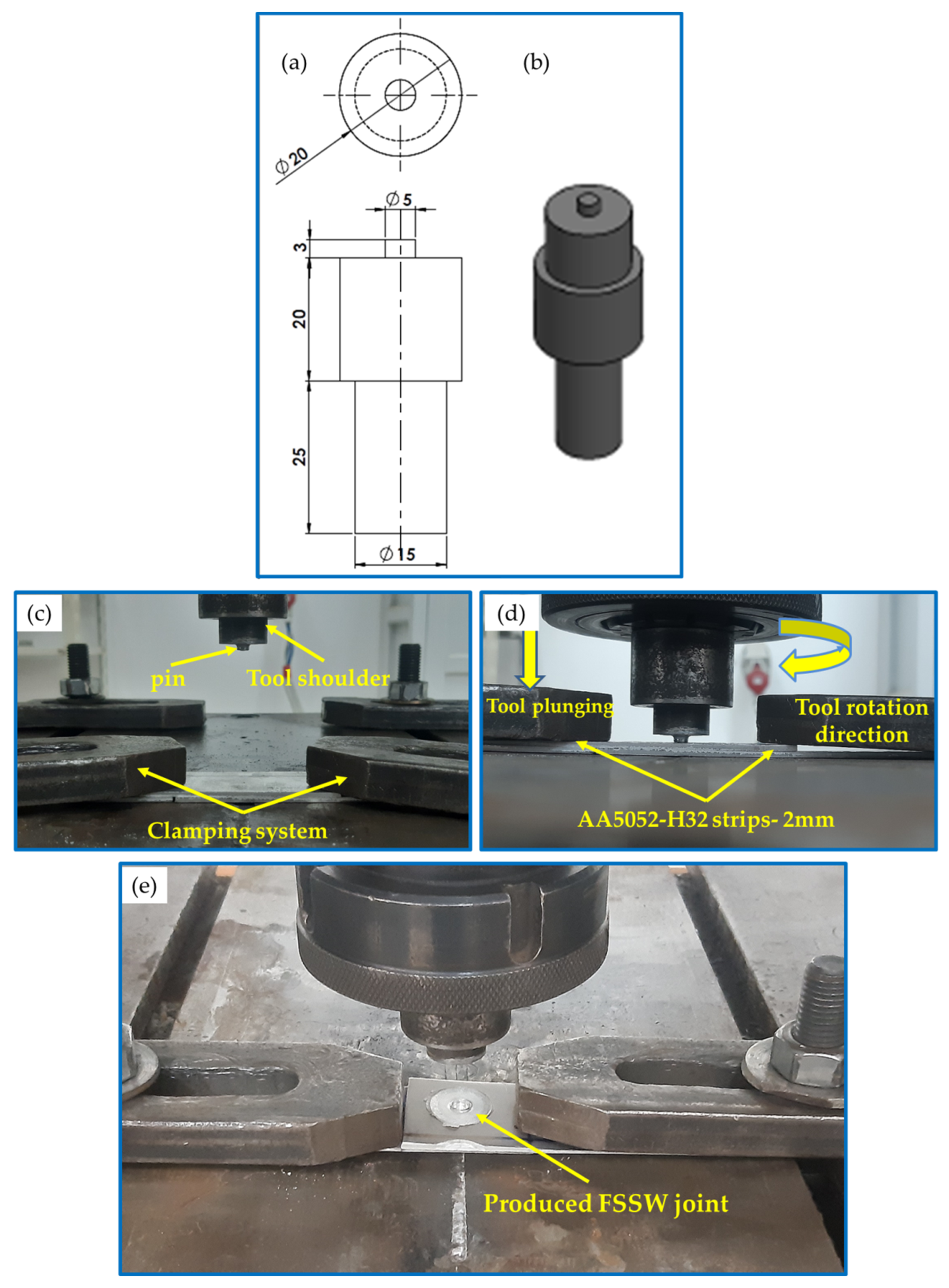
Figure 1. (a) Schematic drawing, (b) isometric image showing the FSSW tool (all dimensions are in mm), and (ce) FSSW stages.
Materials 16 03423 g001
Figure 2. Schematic showing the target zones for hardness measurements during the hardness test performed on the FSSW AA5052 lap joints.
Materials 16 03423 g002
Figure 3. (a) Drawing and isometric showing the tensile–shear test specimen (b). Photographic image of the joint specimen during the tensile-shear test, and (c) High magnification of (d).
Materials 16 03423 g003
Figure 4. The top appearance of the AA5052-H32 FSSW joints produced at a 2 s dwell time and different rotation speeds of (a) 500, (b) 1000, and (c) 1500 rpm.
Materials 16 03423 g004
Figure 5. The heat input energy versus rotation speed to produce the AA5052-H32 FSSW joints at a 2 s dwell time.
Materials 16 03423 g005
Figure 6. Typical macrographs showing the FSSW joint cross-sections processed at different rotation speeds of (a) 500, (b) 1000, and (c) 1500 rpm and a constant dwell time of 2 s.
Materials 16 03423 g006
Figure 7. The IPF maps for the BM in (a) and the SZ of the FSSWed AA5052-H32 at a constant dwell time of 2 s and different tool rotation speeds of (b) 1500, (c) 1000 and (d) 500 rpm with the high angle grain boundaries greater than 15o of misorientation superimposed in black lines.
Materials 16 03423 g007
Figure 8. IPF maps after rotation to align the shear reference frame with the FSSW reference frame for the data presented in Figure 7 for different tool rotation speeds of (a) (1500 rpm), (b) (1000 rpm), and (c) (500 rpm).
Materials 16 03423 g008
Figure 9. Grain size distributions obtained from the EBSD data presented in Figure 7 for the BM in (a) and the SZ of the FSSWed AA5052-H32 produced at a constant dwell time of 2 s and different tool rotation speeds of (b) 1500, (c) 1000, and (d) 500 rpm.
Materials 16 03423 g009
Figure 10. Average grain size variation in the BM to the different rotation speeds FSSWed joints.
Materials 16 03423 g010
Figure 11. Grain boundary maps with HABs > 15° in black lines and low-angle boundaries 5° < LABs < 15° in red lines for the BM in (a) and the SZ in the FSSWed AA5052-H32 at a constant dwell time of 2 s and different tool rotation speeds of (b) 1500, (c) 1000, and (d) 500 rpm.
Materials 16 03423 g011
Figure 12. Misorientation angle distributions obtained from the EBSD data presented in Figure 7 for the BM in (a) and the SZ in the FSSWed AA5052-H32 at a constant dwell time of 2 s and different tool rotation speeds of (b) 1500, (c) 1000, and (d) 500 rpm.
Materials 16 03423 g012
Figure 13. The 001, 101, and 111 pole figures calculated using the EBSD data presented in Figure 7 for the BM in (a) and the SZ in FSSWedAA5052-H32 at a constant dwell time of 2 s and different tool rotation speeds of (b) 1500, (c) 1000, and (d) 500 rpm.
Materials 16 03423 g013
Figure 14. Orientation distribution function (ODF) sections at φ2 = 45° and φ2 = 0° calculated using the EBSD data presented in Figure 7 for the BM in (a) and the SZ in the FSWed AA5052-H32 at a constant dwell time of 2s and different tool rotation rates of (a) 1500, (b) 1000, and (c) 500 rpm.
Materials 16 03423 g014
Figure 15. Schematic showing the ODF sections at φ2 = 45° and φ2 = 0° with the simple shear ideal texture components presented at their ideal positions.
Materials 16 03423 g015
Figure 16. Hardness contour maps for the AA5052-H32 FSSWed specimens processed at rotation speeds of (a) 500, (b) 1000, and (c) 1500 rpm and a constant dwell time of 2 s.
Materials 16 03423 g016
Figure 17. Average hardness values in the welded zones (SZ, TMAZ, and HAZ) as a function of the applied various rotational speeds and a constant dwell time of 2 s.
Materials 16 03423 g017
Figure 18. Tensile–shear curves in terms of load against the elongation of the AA5052-H32 welds produced at different rotation speeds (500–1500) and a 2 s dwell time.
Materials 16 03423 g018
Figure 19. Maximum tensile–shear load of the AA5052-H32 FSSW joints versus the tool rotation speed.
Materials 16 03423 g019
Figure 20. Fracture surface SEM images showing the AA5052-H32 BM (a) ETD and (b) VCD.
Materials 16 03423 g020
Figure 21. Photographs showing the fracture location of the AA5052-H32 FSSWed joints after tensile–shear testing.
Materials 16 03423 g021
Figure 22. Fracture surface SEM images showing (a) the top view of the separated lower AA5052-H32 sheet FSSWed at 2 s and 500 rpm after failing during the tensile test and (b,c) different magnifications.
Materials 16 03423 g022
Figure 23. Fracture surface SEM images showing (a) the top view of the separated lower AA5052-H32 sheet FSSWed at 2 s and 1000 rpm after failing during the tensile test and (b,c) different magnifications.
Materials 16 03423 g023
Figure 24. Fracture surface SEM images showing (a) the top view of the separated lower AA5052-H32 sheet FSSWed at 2 s and 1500 rpm after failing during the tensile test and (b,c) different magnifications.
Materials 16 03423 g024
Table 1. The chemical composition the AA5052-H32 Al alloy.
ElementsZnFeTiSiMgCrMnCuVAl
(in wt. %)0.2000.2580.0180.1272.4900.1950.0900.0010.001Bal.
Table 2. Partial fibers and ideal components of simple shear texture in face-centered cubic (FCC) metals [63,65].
A/B FiberShear PlaneShear DirectionEuler Angles (°)
(hkl)<uvw>φ1Φφ2
A 1 * 11 1 ¯ 2 1 ¯ 1 35.26/215.26450/90
125.269045
A 2 * 11 1 ¯ 112 144.74450/90
54.74/234.749045
A ¯ 11 1 ¯ 1 1 ¯ 0 035.2645
A ¯ 11 1 ¯ 101 18035.2645
B{112} 1 1 ¯ 0 0/120/24054.7445
B ¯ 1 ¯ 1 ¯ 2 ¯ 1 1 ¯ 0 60/18054.7445
C{001} 1 1 ¯ 0 90/270450/90
0/1809045
Disclaimer/Publisher’s Note: The statements, opinions and data contained in all publications are solely those of the individual author(s) and contributor(s) and not of MDPI and/or the editor(s). MDPI and/or the editor(s) disclaim responsibility for any injury to people or property resulting from any ideas, methods, instructions or products referred to in the content.