
Illumination of Interior Spaces through Structures Made of Unified Slabs of High-Performance Light-Transmitting Concrete with Embedded Optical Fibers


Abstract
1. Introduction
2. Theory and Definition
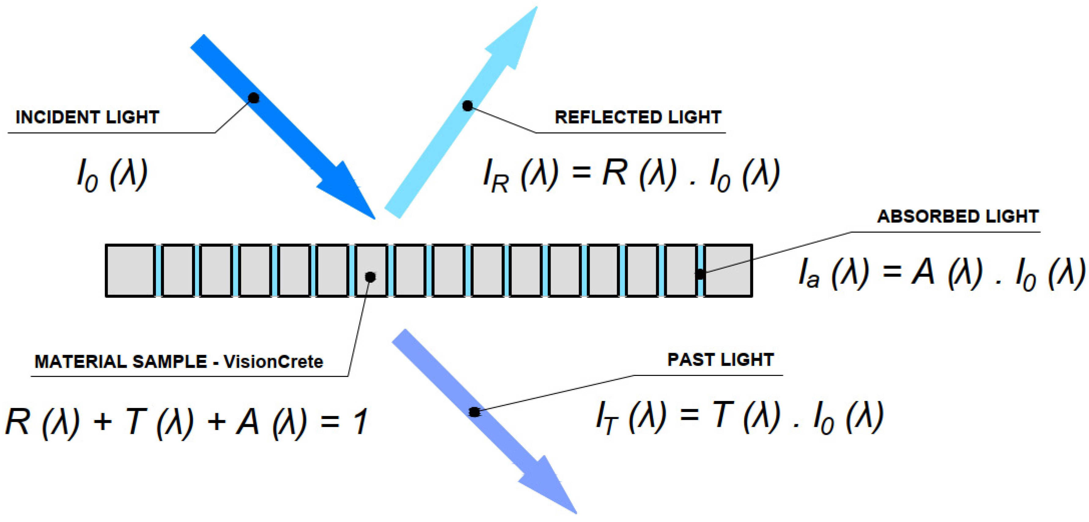
2.1. Theory of Light-Transmitting Concrete
2.2. Physical Definition of Solar Radiation
3. Materials and Sample Production
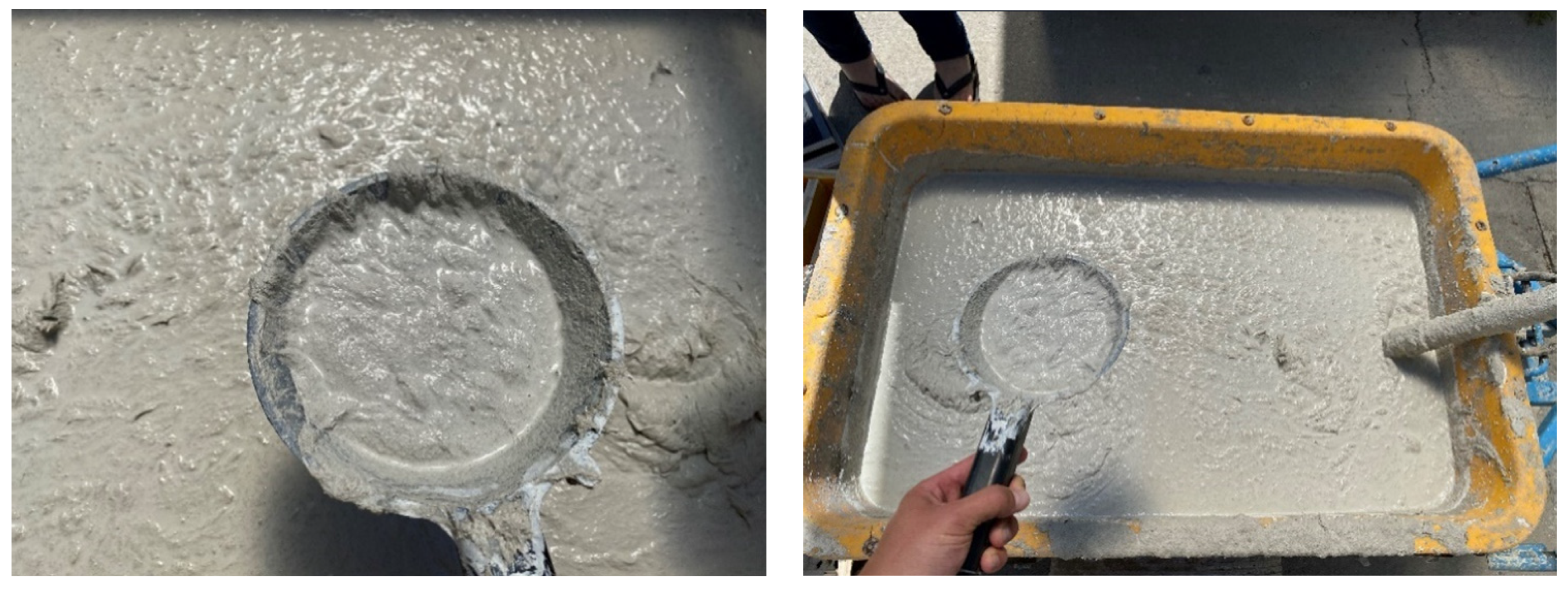
3.1. Concrete Mixture
3.2. Glass Fiber Reinforcement
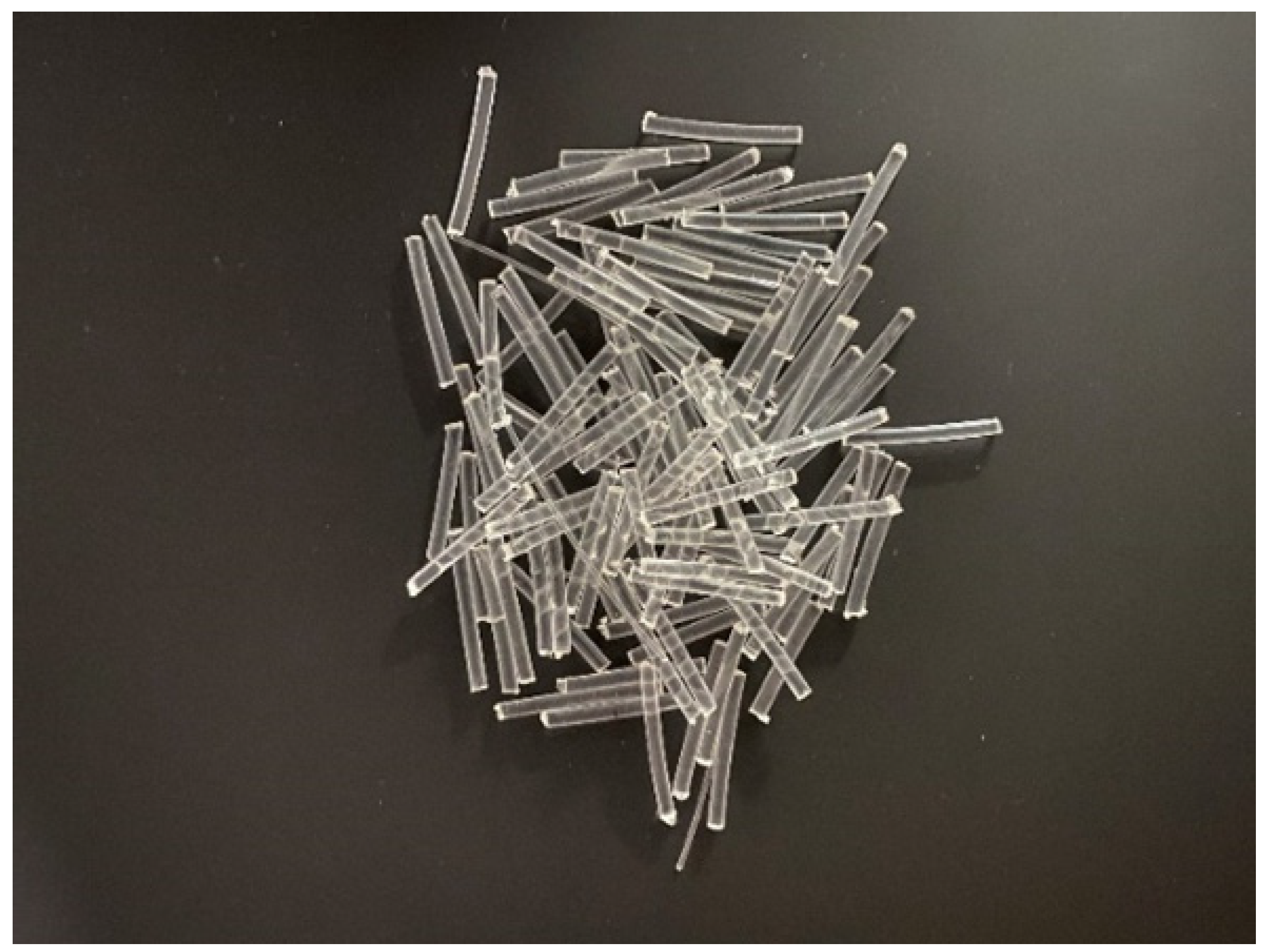
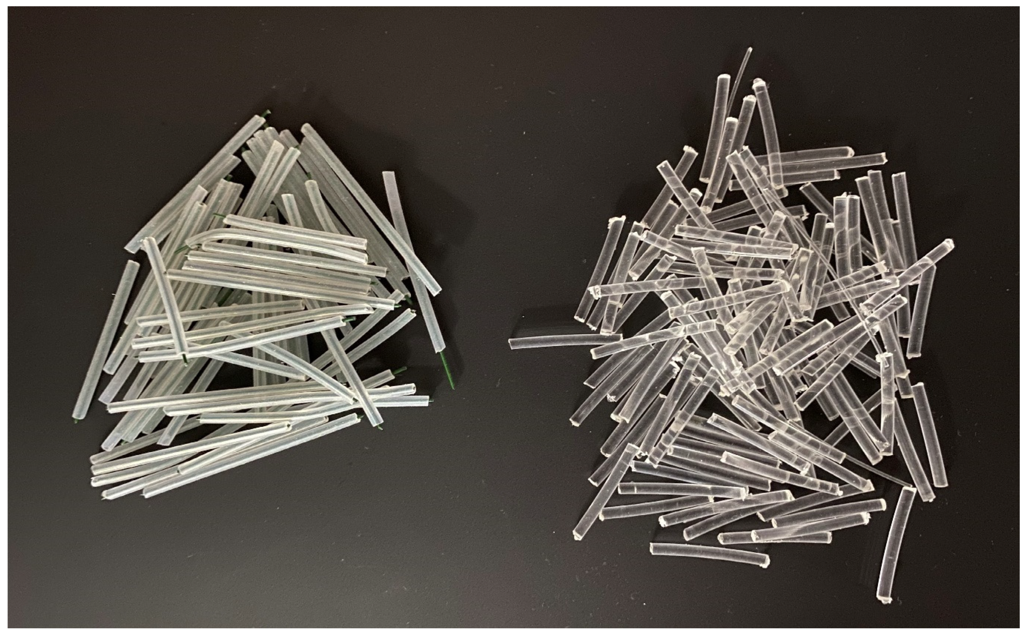
3.3. Optical Fiber Light Transmission

| POF—Multimode—Technical Parameters (Plastic Optical Fibers) | |
|---|---|
| Material: | Optical Loss (dB/km) |
| PMMA—polymethylmethacrylate | 200 |
| The greatest angle of incidence (°) | External refractive index: |
| 75 | n1 = 1.402 (glass n = 1.5–1.9) |
| Operating temperature (°C) | Refractive index of the core layer: |
| −10 + 70 | n2 = 1.516 |
| Range of wavelengths: | Minimum bending radius: |
| 380–780 | 8 × D |


- (1)
- Multimode—Step-index fiber;
- (2)
- Multimode—Graded-index fiber;
- (3)
- Monomode—Single-mode fiber.

3.4. Design of the Samples
3.5. Samples Specification
- (1)
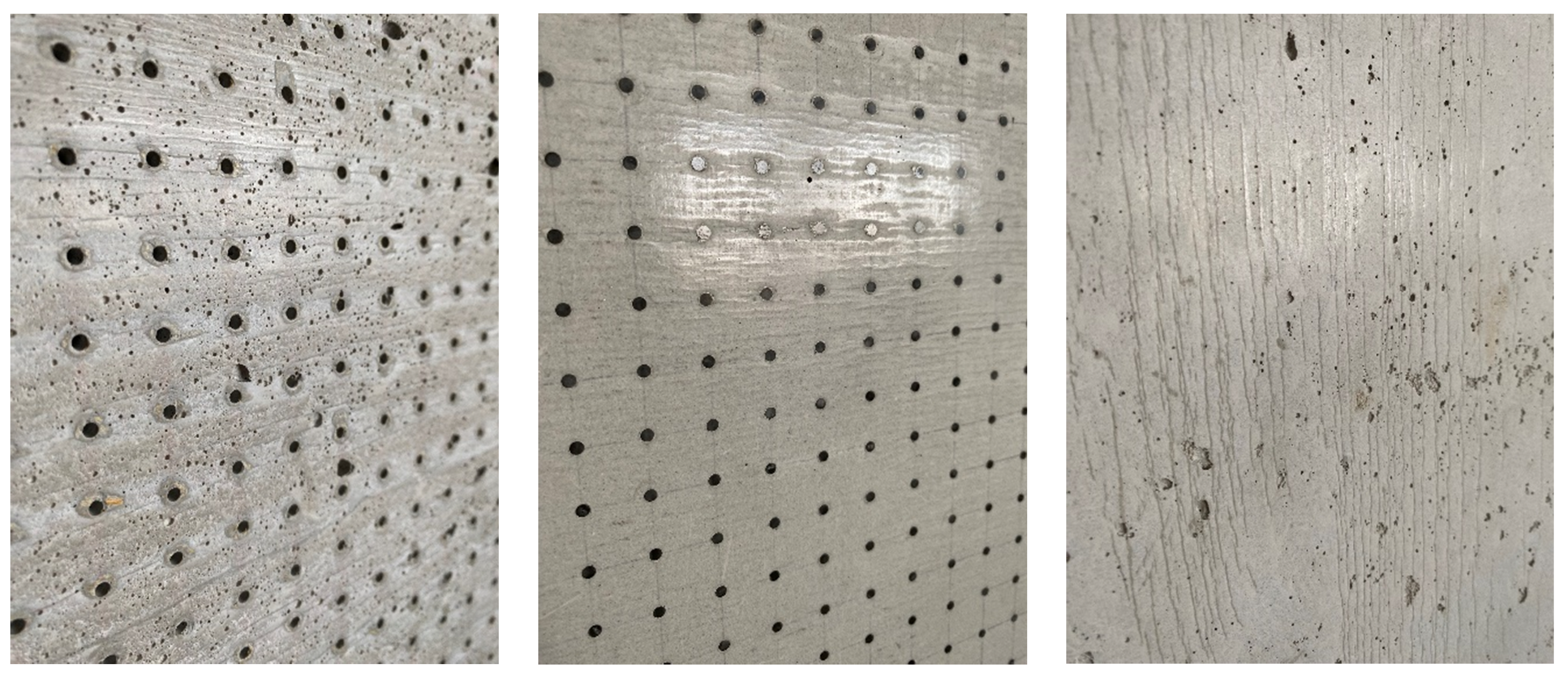
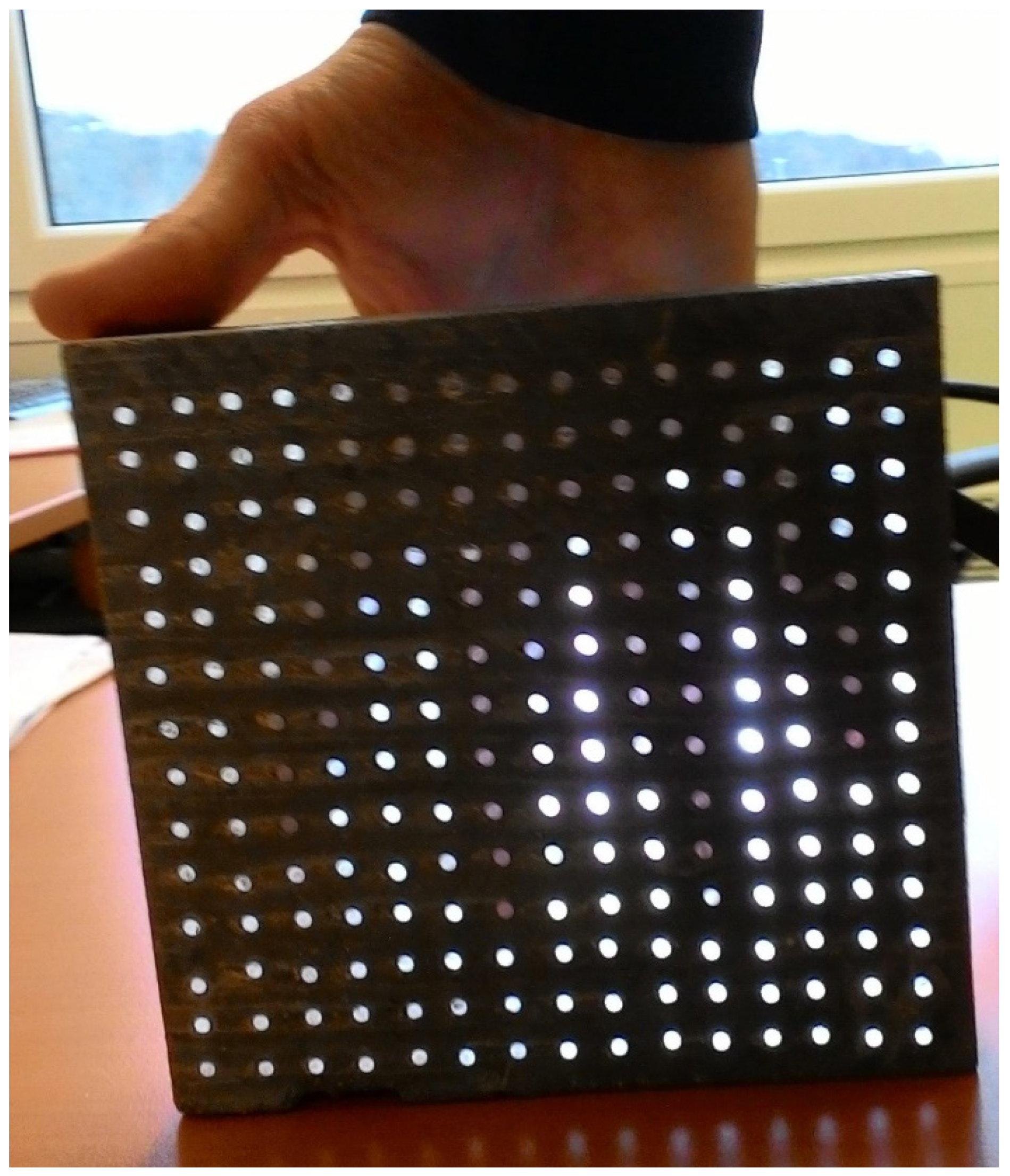
- Concrete slab with optical fibers of thickness 3 mm and Anti-Crak HP (62.4) glass fibers, dimensions of 250 × 250 × 20 mm, POF placed perpendicular to the exact grid at a distance of 15 × 15 mm, as shown in the Figure 10.
- (2)
- Concrete slab with optical fibers of thickness 3 mm and Anti-Crak HP (62.4) glass fibers, dimensions of 250 × 250 × 30 mm, POF placed perpendicular to the exact grid at a distance of 15 × 15 mm, as shown in the Figure 10.
- (1)
- Concrete slab with air holes of thickness 3 mm and Anti-Crak HP (62.4) glass fibers, dimensions of 250 × 250 × 20 mm, air holes placed perpendicular to the exact grid at a distance of 15 × 15 mm, as shown in Figure 11.
- (2)
- Concrete slab with air holes of thickness 3 mm and Anti-Crak HP (62.4) glass fibers, dimensions of 250 × 250 × 30 mm, air holes placed perpendicular to the exact grid at a distance of 15 × 15 mm, as shown in the Figure 11.
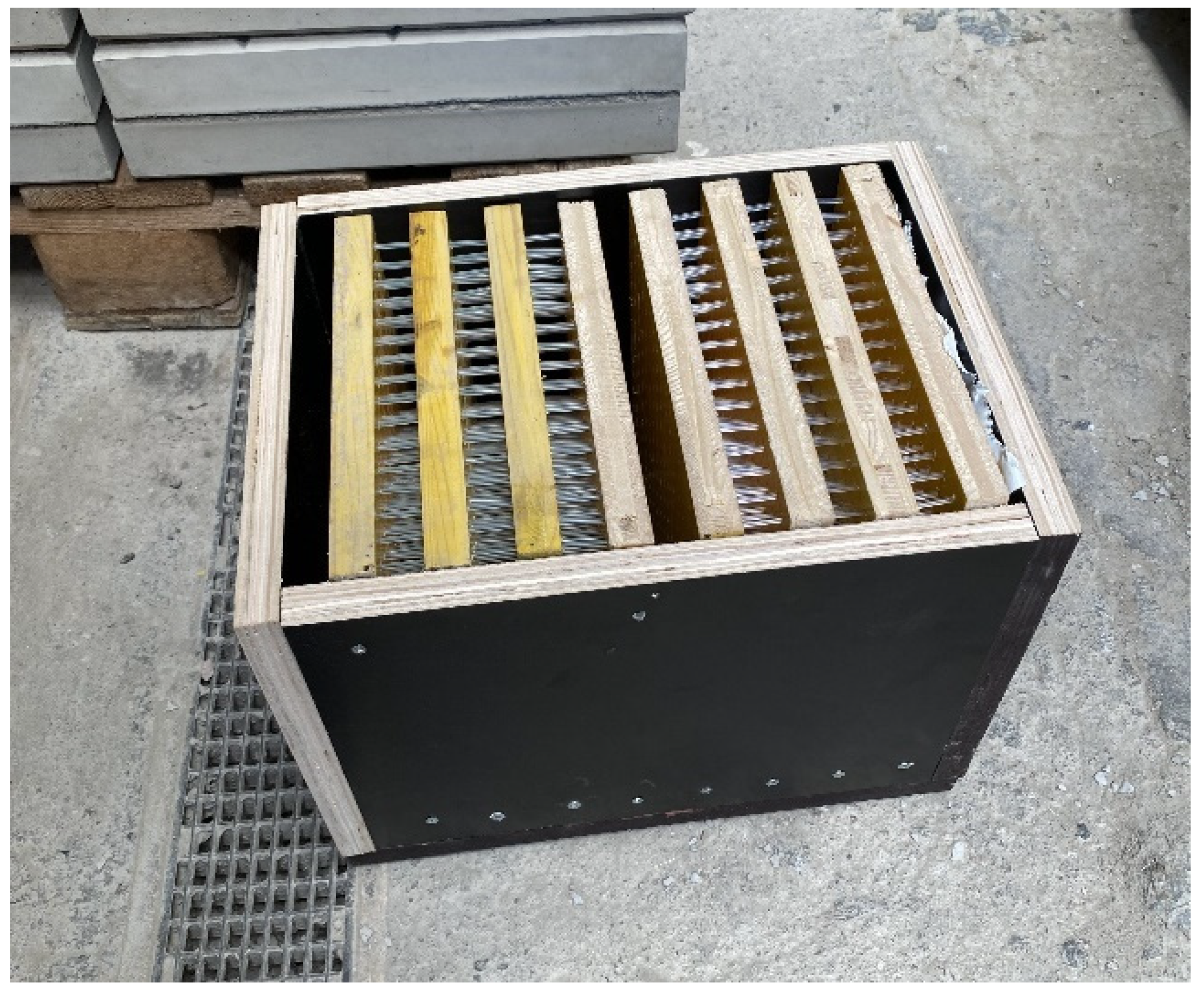
3.6. Production of Samples
4. Methods and Experimental Results
4.1. Experimental Part 1—Properties and Transmission
4.1.1. Daylight Assessment
4.1.2. Daylight Factor Assessment
4.1.3. Quantitative and Qualitative Level of Daylight
4.1.4. Light Reflection Factor Assessment
4.1.5. Measurement of the Light Transmission Factor
4.1.6. Measuring Devices and Aids
- measuring angle 1/3°;
- viewing angle 9°;
- range 0.001 cd·m2 to 299.99 cd·m2;
- focusing distance from 1014 mm to infinity;
- relative spectral response of 8% of the CIE spectral luminous efficiency V (λ).
- accuracy ±2% ±1 digital displayed value;
- equipped with a cosine deviation filter;
- range from 0.001 lx to 299.9 lx;
- relative spectral response of 6% of the CIE spectral luminous efficiency.
4.1.7. Daylight Transmission Test of a Simulated Horizontal Structure Made of Light-Transmitting Concrete on a Down-Scaled Model of the Room
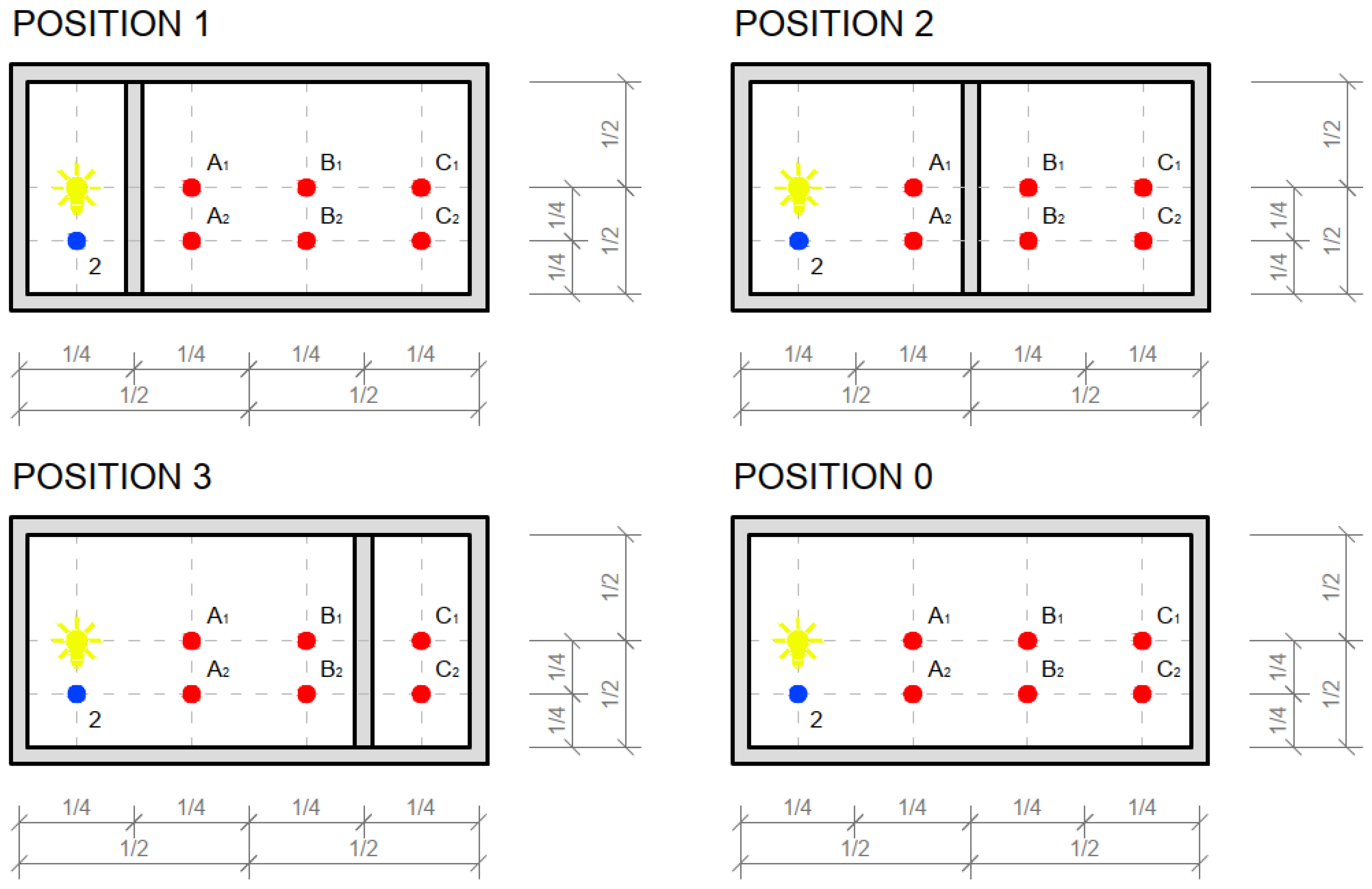
4.1.8. Measurement of Light Transmission from an Artificial Light Source through a Simulated Vertical Structure from Light-Transmitting Concrete between Two Rooms in the Down-Scaled Model
4.2. Experimental Part 2—Strength Characteristics
4.2.1. Characteristics of the Strength of Translucent Concrete Slabs
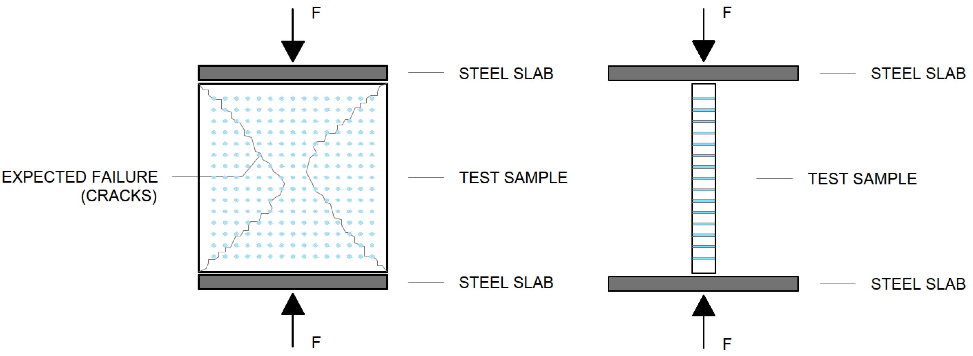
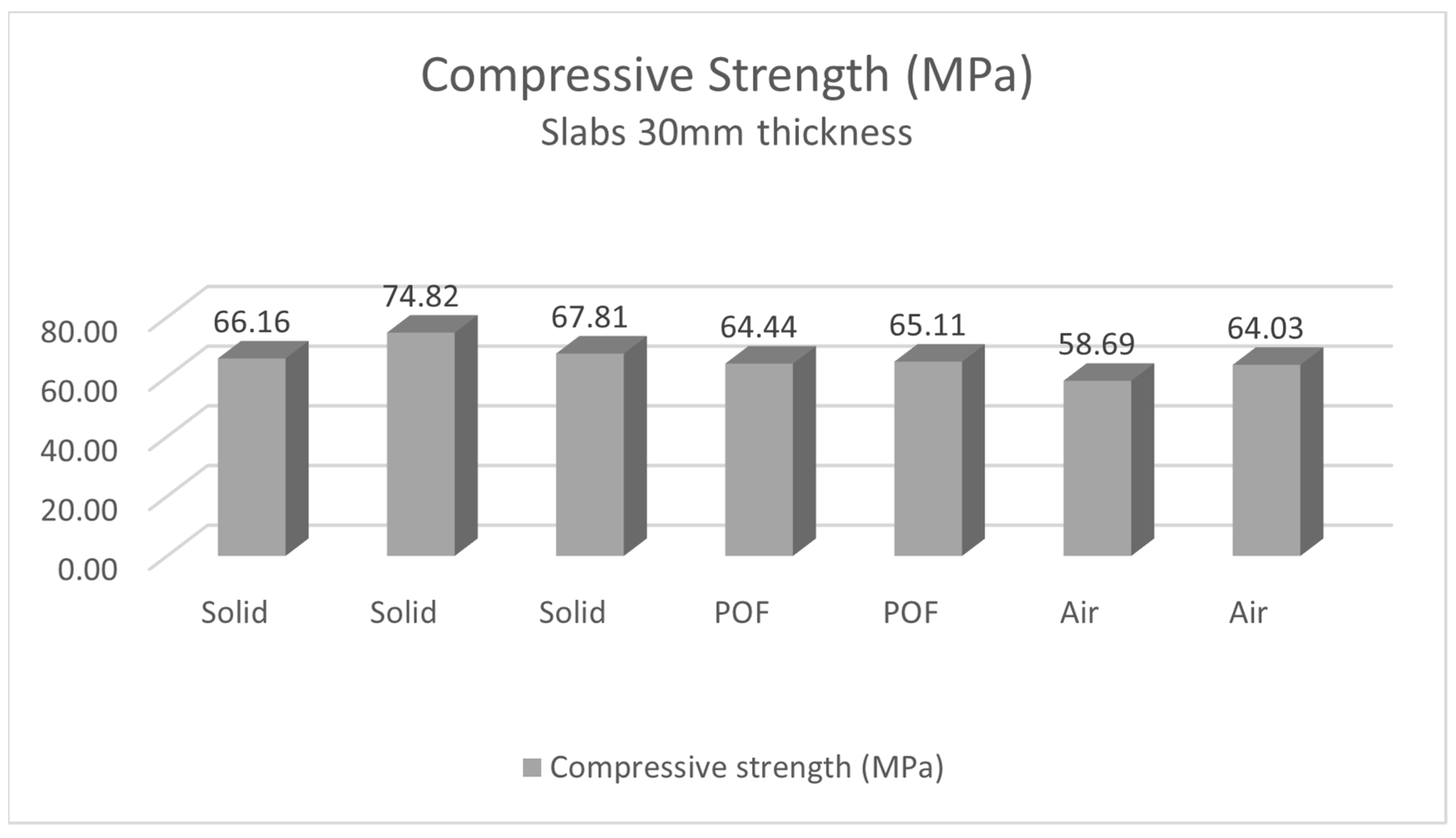
4.2.2. Measurement of Compressive Strength of Light Transmitting Concrete Slabs
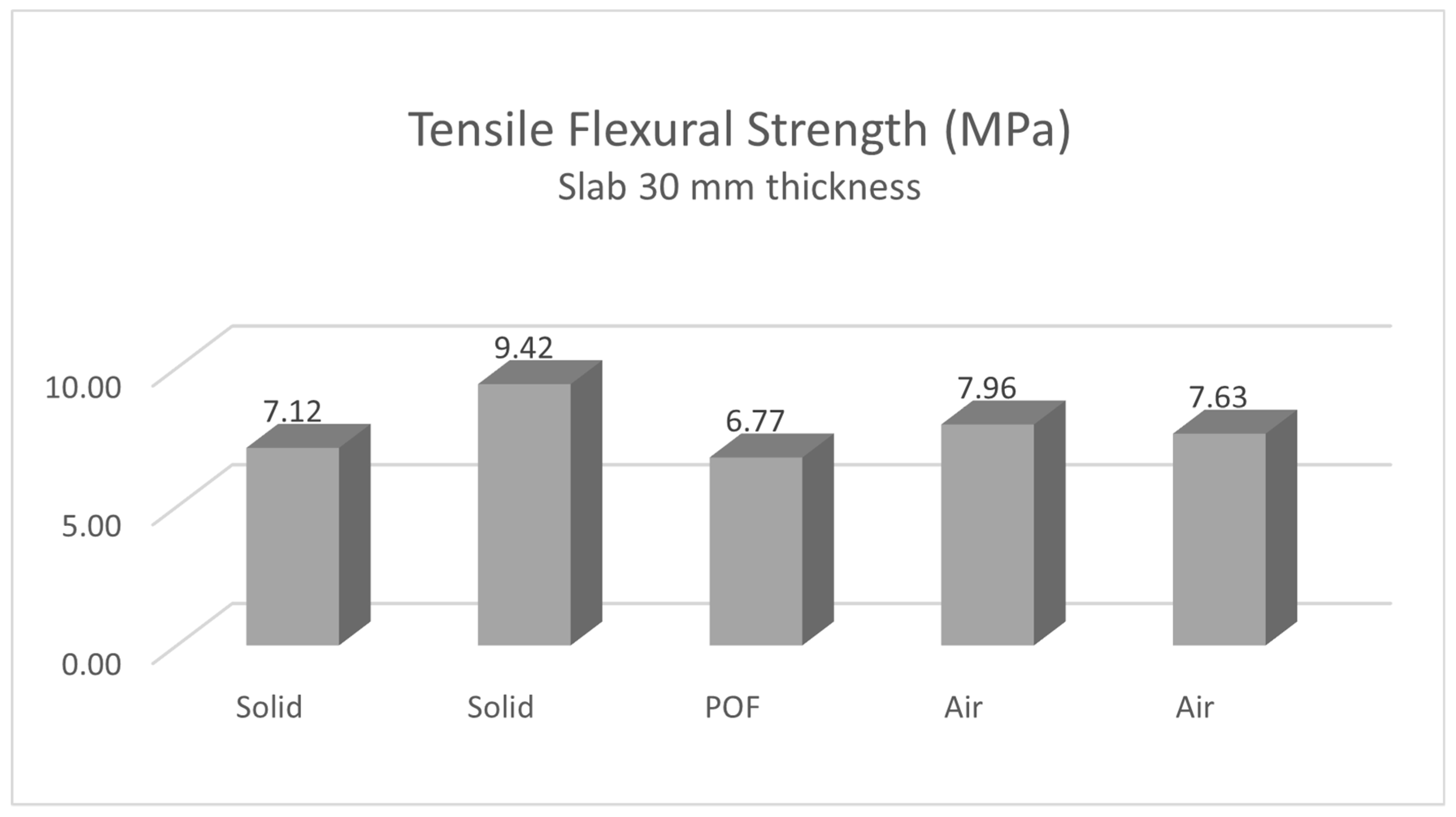
4.2.3. Measurement of Tensile Flexural Strength of Light Transmitting Concrete Slabs
5. Conclusions and Discussion
Author Contributions
Funding
Institutional Review Board Statement
Informed Consent Statement
Data Availability Statement
Acknowledgments
Conflicts of Interest
References
- Paul, S.; Dutta, A. Translucent Concrete. Int. J. Sci. Res. Publ. 2013, 10, 110. Available online: https://www.ijsrp.org/research-paper-1013.php?rp=P221895 (accessed on 13 March 2023).
- Valambhiya, H.B.; Tuvar, T.J.; Rayjada, P.V. History and case study on light transmitting concrete. J. Emerg. Technol. Innov. Res. 2017, 4, 1. Available online: https://www.jetir.org/papers/JETIR1701004.pdf (accessed on 13 March 2023).
- Litracon Bft. Hungary. 2004. Available online: http://www.litracon.hu/ (accessed on 13 March 2023).
- Lucem GmbH, Germany. 2007. Available online: https://www.lucem.de/ (accessed on 13 March 2023).
- Luccon Lichtbeton GmbH (A Brand of Lucem GmbH), Austria. 2006. Available online: https://www.luccon.com/ (accessed on 13 March 2023).
- Graveli s.r.o., LiCrete, Czech Republic. 2012. Available online: https://www.gravelli.com/en/our-concrete/ (accessed on 13 March 2023).
- Edris, W.F.; Odah, E.; Abu-Qasmieh, I.; Hendy, A. Mechanical Properties of Translucent Concrete Using Plexiglass Bars and Fiberglass. Civ. Eng. Arch. 2021, 9, 293–300. [Google Scholar] [CrossRef]
- Suchorab, Z.; Franus, M.; Barnat-Hunek, D. Properties of Fibrous Concrete Made with Plastic Optical Fibers from E-Waste. Materials 2020, 13, 2414. [Google Scholar] [CrossRef]
- Nam, H.P.; Hai, N.M.; Van Huong, N.; Quang, P.D.; Tuan, N.D.; Hai, D.V.; Binh, N.T.; Vy, T.Q. Experimental study on 80 MPa grade light transmitting concrete with high content of optical fibers and eco-friendly raw materials. Case Stud. Constr. Mater. 2023, 18, e01810. [Google Scholar] [CrossRef]
- Sangeetha, S.P.; Subathra, P.; Divahar, R.; Raj, P.S.A. Strength and light transmitting characteristics of translucent concrete using plastic optic fibers. J. Build. Pathol. Rehabil. 2022, 7, 57. [Google Scholar] [CrossRef]
- Lian, F.; Yin, Z. Mechanical, light transmittance properties and simulation study of sustainable translucent lightweight aggregate concrete. Mater. Res. Express 2022, 9, 25507. [Google Scholar] [CrossRef]
- Huang, B.; Mosalam, K.M.; Chiew, S.P. Anidolic Daylight Concentrator of Structural Translucent Concrete Envelope. Berkeley Education Alliance for Research in Singapore. 2013. Available online: https://sinberbest.berkeley.edu/sites/default/files/Anilodic+Daylight+Concentrator+of+Structural+Translucent+Concrete+Envelope_+Baofeng+Huang.pdf (accessed on 13 March 2023).
- Henriques, T.D.S.; Molin, D.C.D.; Masuero, Â.B. Optical fibers in cementitious composites (LTCM): Analysis and discussion of their influence when randomly arranged. Constr. Build. Mater. 2020, 244, 118406. [Google Scholar] [CrossRef]
- Sawant, A.B.; Jugdar, R.V.; Sawant, S.G. Light Transmitting Concrete by Using Optical Fiber. Int. J. Inventive Eng. Sci. 2014, 3, 23–28. Available online: https://www.ijies.org/wp-content/uploads/papers/v3i1/A0558123114.pdf (accessed on 13 March 2023).
- Gawatre, D.W.; Giri, S.D.; Bande, B.B. Transparent concrete as an eco-friendly material for building. Int. J. Eng. Sci. Invent. 2016, 5, 55–62. Available online: https://www.ijesi.org/papers/Vol(5)3/Version-2/I050302055062.pdf (accessed on 13 March 2023).
- Navabi, D.; Javidruzi, M.; Hafezi, M.R.; Mosavi, A. The high-performance light transmitting concrete and experimental analysis of using polymethylmethacrylate optical fibers in it. J. Build. Eng. 2020, 38, 102076. [Google Scholar] [CrossRef]
- Li, Y.; Li, J.; Wan, Y.; Xu, Z. Experimental study of light transmitting cement-based material (LTCM). Constr. Build. Mater. 2015, 96, 319–325. [Google Scholar] [CrossRef]
- Dvořáček, P. New Possibilities in Building Industry and Architecture. Beton 2005, 5, 38–41. [Google Scholar]
- Altlomate, A.; Alatshan, F.; Mashiri, F.; Jadan, M. Experimental study of light-transmitting concrete. Int. J. Sustain. Build. Technol. Urban Dev. 2016, 7, 133–139. [Google Scholar] [CrossRef]
- Li, Y.; Zhang, J.; Cao, Y.; Hu, Q.; Guo, X. Design and evaluation of light-transmitting concrete (LTC) using waste tempered glass: A novel concrete for future photovoltaic road. Constr. Build. Mater. 2021, 280, 122551. [Google Scholar] [CrossRef]
- Zielińska, M.; Ciesielski, A. Analysis of Transparent Concrete as an Innovative Material Used in Civil Engineering. IOP Conf. Series Mater. Sci. Eng. 2017, 245, 22071. [Google Scholar] [CrossRef]
- Kim, B. Light Transmitting Lightweight Concrete with Transparent Plastic Bar. Open Civ. Eng. J. 2017, 11, 615–626. [Google Scholar] [CrossRef]
- Henriques, T.D.S.; Molin, D.C.D.; Masuero, B. Study of the influence of sorted polymeric optical fibers (POFs) in samples of a light-transmitting cement-based material (LTCM). Constr. Build. Mater. 2018, 161, 305–315. [Google Scholar] [CrossRef]
- Tuaum, A.; Shitote, S.; Oyawa, W.; Biedebrhan, M. Structural Performance of Translucent Concrete Façade Panels. Adv. Civ. Eng. 2019, 2019, 4604132. [Google Scholar] [CrossRef]
- Italcementi, S.P.A. I.light, Italy. 1864. Available online: https://www.italcementi.it/it/ilight (accessed on 13 March 2023).
- Mainini, A.G.; Poli, T.; Zinzi, M.; Cangiano, S. Spectral Light Transmission Measure and Radiance Model Validation of an innovative Transparent Concrete Panel for Façades. Energy Procedia 2012, 30, 1184–1194. [Google Scholar] [CrossRef]
- Juan, S.; Zhi, Z. Preparation and Study of Resin Translucent Concrete Products. Adv. Civ. Eng. 2019, 2019, 8196967. [Google Scholar] [CrossRef]
- Wikipedia—The Free Encyclopedia 2001, Air Mass. Available online: https://en.wikipedia.org/wiki/Air_mass_(solar_energy) (accessed on 13 March 2023).
- Ahuja, A.; Mosalam, K.M.; Zohdi, T.I. Computational Modeling of Translucent Concrete Panels. J. Arch. Eng. 2015, 21, B4014008. [Google Scholar] [CrossRef]
- Li, Y.; Xu, Z.Y.; Gu, Z.W.; Bao, Z.Z. Research on the Light Transmitting Cement Mortar. Adv. Mater. Res. 2012, 450–451, 397–401. Available online: https://citeseerx.ist.psu.edu/document?repid=rep1&type=pdf&doi=f8e23e3abd0b2f93967470a6fd98f8c462aab425 (accessed on 13 March 2023). [CrossRef]
- Chiew, S.M.; Ibrahim, I.S.; Ariffin, M.A.M.; Lee, H.-S.; Singh, J.K. Development and properties of light-transmitting concrete (LTC)—A review. J. Clean. Prod. 2020, 284, 124780. [Google Scholar] [CrossRef]
- Shenoy, A.; Nayak, G.; Tantri, A.; Shetty, K.K. Thermal transmission characteristics of plastic optical fibre embedded light transmitting concrete. Mater. Today Proc. 2022, 65, 1759–1773. [Google Scholar] [CrossRef]
- Ahuja, A.; Mosalam, K.M. Evaluating energy consumption saving from translucent concrete building envelope. Energy Build. 2017, 153, 448–460. [Google Scholar] [CrossRef]
- Su, X.; Zhang, L.; Liu, Z.; Luo, Y.; Lian, J.; Liang, P. Daylighting performance simulation and analysis of translucent concrete building envelopes. Renew. Energy 2020, 154, 754–766. [Google Scholar] [CrossRef]
- Su, X.; Zhang, L.; Luo, Y.; Liu, Z. An energy analysis of translucent concrete embedded with inclined optical fibers. Energy Build. 2022, 273, 112409. [Google Scholar] [CrossRef]
- Huang, B.; Wang, Y.; Lu, W.; Cheng, M. Fabrication and energy efficiency of translucent concrete panel for building envelope. Energy 2022, 248, 123635. [Google Scholar] [CrossRef]
- Sasidharan, J.; Naga Sai Teja, A.; Sakthivel, K.; Manickavel, D.; Mohan, S.K. Translucent Concrete. Int. J. Eng. Res. Technol. 2017, 6, 782–786. Available online: https://www.ijert.org/research/translucent-concrete-IJERTV6IS040596.pdf (accessed on 13 March 2023). [CrossRef]
- Mahto, S.; Kujure, J. Light Weight Translucent Concrete. Int. J. Adv. Mech. Civ. Eng. 2017, 3, 112–115. Available online: https://www.iraj.in/journal/journal_file/journal_pdf/13-373-1503725247112-115.pdf (accessed on 13 March 2023).
- Arias-Erazo, J.; Villaquirán-Caicedo, M.A.; Goyes, C.E. Ecological light transmiting concrete made from glass waste and acrylic sheets. Constr. Build. Mater. 2021, 304, 124644. [Google Scholar] [CrossRef]
- Pagliolico, S.L.; Verso, V.R.L.; Torta, A.; Giraud, M.; Canonico, F.; Ligi, L. A Preliminary Study on Light Transmittance Properties of Translucent Concrete Panels with Coarse Waste Glass Inclusions. Energy Procedia 2015, 78, 1811–1816. [Google Scholar] [CrossRef]
- Hu, H.; Zha, X.; Li, Z.; Lv, R. Preparation and performance study of solar pavement panel based on transparent Resin-Concrete. Sustain. Energy Technol. Assess. 2022, 52, 102169. [Google Scholar] [CrossRef]
- Sklocement Beneš s.r.o., Czech Republic. 1991. Available online: https://www.sklocement.cz/sklenena-vlakna-cem-fil/anti-crak-hp/ (accessed on 13 March 2023).
- Spiesz, P.; Rouvas, S.; Brouwers, H. Utilization of waste glass in translucent and photocatalytic concrete. Constr. Build. Mater. 2016, 128, 436–448. [Google Scholar] [CrossRef]
- Wikipedia—The Free Encyclopedia 2001, Optical Fiber. Available online: https://en.wikipedia.org/wiki/Optical_fiber (accessed on 13 March 2023).
- Jiao, P.; Huang, Y.; Fu, Y.; Wang, Y.; Wang, J.; Du, Y.; Zhang, J.; Jia, J. Design of optical fiber path for tapered optical fiber array and improvement of light transmission uniformity. Opt. Fiber Technol. 2022, 74, 103149. [Google Scholar] [CrossRef]
- Abdulmajeed, N.S.; Said, S.H. Compressive characteristics of resin translucent cement mortar (RTCM) used in the external walls to rationalize the energy spent inside the building. Case Stud. Constr. Mater. 2022, 17, e01687. [Google Scholar] [CrossRef]
- Li, Y.; Li, J.; Guo, H. Preparation and study of light transmitting properties of sulfoaluminate cement-based materials. Mater. Des. 2015, 83, 185–192. [Google Scholar] [CrossRef]
- Ayesta, I.; Azkune, M.; Illarramendi, M.A.; Arrospide, E.; Zubia, J.; Durana, G. Fabrication and characterization of active polymer optical fibers with a ring-doped structure. Opt. Fiber Technol. 2023, 75, 103209. [Google Scholar] [CrossRef]
- Subathra, P.; Sangeetha, S. Study on pellucid concrete incorporating optical fibers–A review. Mater. Today Proc. 2021, 45, 6682–6686. [Google Scholar] [CrossRef]
- Luhar, I.; Luhar, S.; Savva, P.; Theodosiou, A.; Petrou, M.F.; Nicolaides, D. Light Transmitting Concrete: A Review. Buildings 2021, 11, 480. [Google Scholar] [CrossRef]
- Kashiyani, B.K.; Raina, V.; Pitroda, J.; Shah, B.K. A study of Transparent Concrete: A Novel Architectural Material to Explore Construction Sector. Int. J. Eng. Innov. Technol. 2013, 8, 83–87. Available online: https://www.ijeit.com/vol%202/Issue%208/IJEIT1412201302_18.pdf (accessed on 13 March 2023).
- Shiningfiber Company, Shenzhen, China. Available online: https://shiningfiber.com/types-of-optical-fiber/ (accessed on 13 March 2023).
- Weisová, T. Analýza Denního Osvětlení v Učebnách Základních Škol. Diploma Thesis, Czech Technical University, Prague, Czech Republic, 2018. Available online: https://dspace.cvut.cz/bitstream/handle/10467/78057/F1-DP-2018-Weisova-Tereza-DP_Weisova_2018.pdf?sequence=-1&isAllowed=y (accessed on 13 March 2023).
- Vychytil, J.; Kaňka, J. Stavební Světelná Technika: Přednášky; Czech Technical University: Prague, Czech Republic, 2016; ISBN 978-80-01-06060-5. [Google Scholar]
- SN 730580-2; Denní Osvětlení Budov: Část 2: Denní Osvětlení Obytných Budov. Úřad pro Techniku Normalizaci, Metrologii a státní Zkušebnictví (UNMZ): Prague, Czech Republic, 2007.
- SN 730580-1; Denní Osvětlení Budov: Část 1: Základní Požadavky. Úřad pro Techniku Normalizaci Metrologii a státní Zkušebnictví (UNMZ): Prague, Czech Republic, 2007.
- SN 730580-1; ZMĚNA Z1: Denní Osvětlení Budov: Část 1: Základní Požadavky. Úřad pro Techniku Normalizaci Metrologii a státní Zkušebnictví (UNMZ): Prague, Czech Republic, 2011.
- SN 730580-1; ZMĚNA Z2: Denní Osvětlení Budov: Část 1: Základní Požadavky. Úřad pro Techniku Normalizaci Metrologii a státní Zkušebnictví (UNMZ): Prague, Czech Republic, 2017.
- Chiew, S.M.; Ibrahim, I.S.; Sarbini, N.N.; Ariffin, M.A.M.; Lee, H.S.; Singh, J.K. Development of light-transmitting concrete—A review. Mater. Today Proc. 2020, 39, 1046–1050. [Google Scholar] [CrossRef]
- Su, X.; Zhang, L.; Liu, Z.; Luo, Y.; Liang, P.; Lian, J. An optical and thermal analysis of translucent concrete considering its dynamic transmittance. J. Clean. Prod. 2022, 364, 132588. [Google Scholar] [CrossRef]
- Chiew, S.M.; Ibrahim, I.S.; Ariffin, M.A.M.; Lee, H.-S.; Singh, J.K. Evaluation of light transmittance performance of light-transmitting concrete with optical fibre. Constr. Build. Mater. 2022, 351, 128949. [Google Scholar] [CrossRef]
- SN 360011-1; Měření Osvětlení Prostorů—Část 1: Základní Ustanovení. Úřad pro Techniku Normalizaci, Metrologii a státní Zkušebnictví (UNMZ): Prague, Czech Republic, 2014.
- Palanisamy, C.; Krishnaswami, N.; Velusamy, S.K.; Krishnamurthy, H.; Velmurugan, H.K.; Udhayakumar, H. Transparent concrete by using optical fibre. Mater. Today Proc. 2022, 65, 1774–1778. [Google Scholar] [CrossRef]
- Raut, Z.P.; Dhanke, S.S.; Lanjewar, V.R.; Mahadule, A.; Kolte, M. Light Transfer through Concrete by using Optical Fiber. Int. J. Innov. Res. Technol. 2020, 7, 305–309. Available online: https://ijirt.org/master/publishedpaper/IJIRT150070_PAPER.pdf (accessed on 13 March 2023).
- SN EN 12390-3; Zkoušení Ztvrdlého Betonu: Část 3: Pevnost v Tlaku Zkušebních Těles. Úřad pro Techniku Normalizaci Metrologii a statni Zkušebnictví (UNMZ): Prague, Czech Republic, 2009.
- SN EN 12390-5; Zkoušení Ztvrdlého Betonu: Část 5: Stanovení Pevnosti v Tahu Ohybem Zkušebních Těles. Úřad pro Techniku Normalizaci, Metrologii a státní Zkušebnictví (UNMZ): Prague, Czech Republic, 2009.
- Said, S.H. State-of-the-art developments in light transmitting concrete. Mater. Today Proc. 2020, 33, 1967–1973. [Google Scholar] [CrossRef]
- Tahwia, A.M.; Abdel-Raheem, A.; Abdel-Aziz, N.; Amin, M. Light transmittance performance of sustainable translucent self-compacting concrete. J. Build. Eng. 2021, 38, 102178. [Google Scholar] [CrossRef]
- Tahwia, A.M.; Abdelaziz, N.; Samy, M.; Amin, M. Mechanical and light transmittance properties of high-performance translucent concrete. Case Stud. Constr. Mater. 2022, 17, e01260. [Google Scholar] [CrossRef]


| Components of the HPC Mixture | |
|---|---|
| Components | Approximate Density (kg/m³) |
| Aggregate 0–4 mm | 947 |
| White Portland Cement I 52.5 R | 628 |
| Bright microsilica | 123 |
| Superplasticizer | 30 |
| Glass fibers—Anticrack HP 12 | 20 |
| Water | 227 |
| TOTAL | 1975 |
| Anti-Crak® HP (62.4) Technical Parameters (Glass Fibers) | ||||
|---|---|---|---|---|
| Fiber Length (mm) | Filament Diameter (µm) | Tex | Lubricant Content (%) ISO 1887: 1980 | Humidity (%) ISO 3344: 1977 |
| 6 | 14 | 45 | 0.08 | 0.3 max |
| 12 | 14 | 45 | 0.08 | 0.3 max |
|
| |||
|
| |||
|
| |||
| ||||
| ||||
| Light Transmission Factor τs,nor (-): | ||
|---|---|---|
| Values of the Light Transmission Factor when Measured against a Sunny Facade | ||
| Slab 250 × 250 mm, with Optical Fibers d = 3 mm, thickness 20 mm | ||
| Ls (cd/m2) | Lo (cd/m2) | τs,nor (-) |
| 158.1 | 4733 | 0.033 |
| 181.7 | 1779 | 0.102 |
| 220.5 | 1398 | 0.158 |
| Values of the light transmission factor when measured against a non-sunlit facade | ||
| Slab 250 × 250 mm, with optical fibers d = 3 mm, thickness 20 mm | ||
| Ls (cd/m2) | Lo (cd/m2) | τs,nor (-) |
| 151.7 | 1166 | 0.130 |
| 387.5 | 1117 | 0.347 |
| 307.0 | 1075 | 0.286 |
| Values of the light transmission factor when measured against a white wall in the room | ||
| Slab 250 × 250 mm, with optical fibers d = 3 mm, thickness 20 mm | ||
| Ls (cd/m2) | Lo (cd/m2) | τs,nor (-) |
| 36.18 | 170.7 | 0.212 |
| 37.94 | 170.8 | 0.222 |
| 39.18 | 171.8 | 0.228 |
| Distribution of the Sky Brightness | ||||
|---|---|---|---|---|
| Zenith: | 12,990 | cd/m2 | 1874 | cd/m2 |
| Horizon: | 3703 | cd/m2 | 1180 | cd/m2 |
| 3892 | cd/m2 | 998 | cd/m2 | |
| 3357 | cd/m2 | 1587 | cd/m2 | |
| 3592 | cd/m2 | 1624 | cd/m2 | |
| Illumination E (lx) and Daylight Factor D (%): | |||
|---|---|---|---|
| Slab 250 × 250 mm, with optical fibers d = 3 mm, thickness 20 mm | |||
| Bod | E (lx) | Eh (lx) | D (%) |
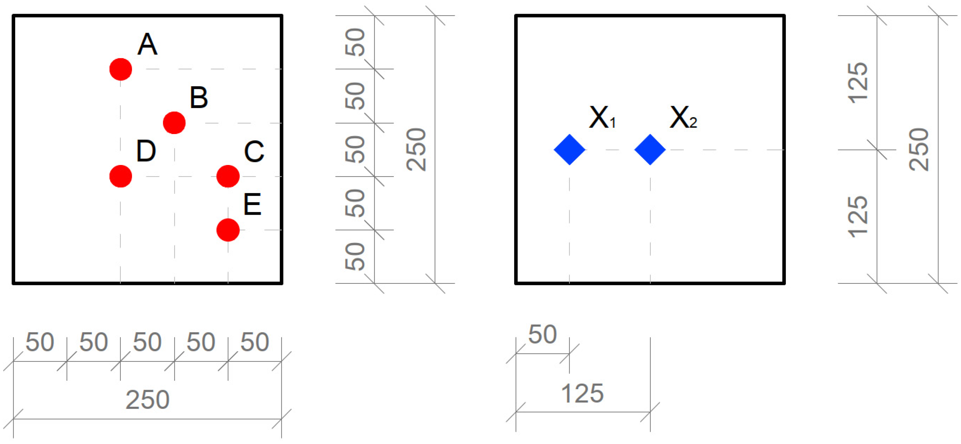
| A | 18.30 | 5250 | 0.348 |
| B | 23.70 | 4860 | 0.488 |
| C | 22.00 | 5180 | 0.425 |
| D | 23.90 | 5190 | 0.460 |
| E | 21.60 | 5940 | 0.363 |
| X1 | 10.70 | 4800 | 0.223 |
| X2 | 15.10 | 4800 | 0.314 |
| Slab 250 × 250 mm, with air holes d = 3 mm, thickness 20 mm | |||
| Bod | E (lx) | Eh (lx) | D (%) |
| A | 1.80 | 5760 | 0.031 |
| B | 2.49 | 5500 | 0.045 |
| C | 2.40 | 5910 | 0.041 |
| D | 2.18 | 4920 | 0.044 |
| E | 3.78 | 5835 | 0.065 |
| X1 | 0.90 | 4600 | 0.020 |
| X2 | 1.14 | 4780 | 0.024 |
| Slab 250 × 250 mm, with optical fibers d = 3 mm, thickness 30 mm | |||
| Bod | E (lx) | Eh (lx) | D (%) |
| A | 18.70 | 4900 | 0.382 |
| B | 23.10 | 5250 | 0.440 |
| C | 23.10 | 5680 | 0.406 |
| D | 20.60 | 4760 | 0.432 |
| E | 22.20 | 5260 | 0.421 |
| X1 | 14.00 | 4640 | 0.301 |
| X2 | 16.00 | 4760 | 0.336 |
| Slab 250 × 250 mm, with air holes d = 3mm, thickness 30 mm | |||
| Bod | E (lx) | Eh (lx) | D (%) |
| A | 1.30 | 4880 | 0.027 |
| B | 1.14 | 5225 | 0.022 |
| C | 0.82 | 5710 | 0.014 |
| D | 0.96 | 4490 | 0.021 |
| E | 0.78 | 5110 | 0.015 |
| X1 | 0.54 | 4720 | 0.011 |
| X2 | 0.50 | 4740 | 0.011 |
| Solid slab 250 × 250 mm, thickness 20 mm and 30 mm | |||
| Bod | E (lx) | Eh (lx) | D (%) |
| A | 0.00 | 4790 | 0.000 |
| B | 0.00 | 5180 | 0.000 |
| C | 0.00 | 5670 | 0.000 |
| D | 0.00 | 4390 | 0.000 |
| E | 0.00 | 5080 | 0.000 |
| X1 | 0.00 | 4670 | 0.000 |
| X2 | 0.00 | 4690 | 0.000 |
| Reflection Factor ρ (-): | ||
|---|---|---|
| Slab 250 × 250 mm, with optical fibers d = 3 mm, thickness 20 mm | ||
| E (lx) | L (cd/m2) | ρ (-) |
| 5010 | 730.6 | 0.458 |
| 5080 | 652.9 | 0.404 |
| 4960 | 767.0 | 0.486 |
| 4980 | 761.5 | 0.480 |
| Slab 250 × 250 mm, with optical fibers d = 3 mm, thickness 30 mm | ||
| E (lx) | L (cd/m2) | ρ (-) |
| 4910 | 754.6 | 0.483 |
| 4930 | 786.6 | 0.501 |
| 4770 | 750.9 | 0.495 |
| 4690 | 740.7 | 0.496 |
| Solid smooth slab 250 × 250 mm, thickness 20 mm | ||
| E (lx) | L (cd/m2) | ρ (-) |
| 4540 | 804.0 | 0.556 |
| 4450 | 793.6 | 0.560 |
| 4450 | 771.9 | 0.545 |
| 4400 | 691.7 | 0.494 |
| Solid smooth slab 250 × 250 mm, thickness 30 mm | ||
| E (lx) | L (cd/m2) | ρ (-) |
| 4070 | 480.4 | 0.371 |
| 4030 | 478.9 | 0.373 |
| 3990 | 510.3 | 0.402 |
| 3920 | 467.0 | 0.374 |
| Solid rude slab 250 × 250 mm, thickness 30 mm | ||
| E (lx) | L (cd/m2) | ρ (-) |
| 4410 | 792.1 | 0.564 |
| 4150 | 687.6 | 0.521 |
| 4110 | 782.0 | 0.598 |
| 4100 | 778.7 | 0.597 |
| Illumination E (lx): | |||
|---|---|---|---|
| Slab 250 × 250 mm, with optical fibers d = 3 mm, thickness 20 mm | |||
| Point | Position 1 | Position 2 | Position 3 |
| E (lx) | E (lx) | E (lx) | |
| A1 | 5.40 | x | x |
| A2 | 3.29 | x | x |
| B1 | 4.28 | 2.23 | x |
| B2 | 3.77 | 1.49 | x |
| C1 | 1.60 | 1.83 | 1.06 |
| C2 | 1.72 | 1.19 | 0.72 |
| Slab 250 × 250 mm, with air holes d = 3 mm, thickness 20 mm | |||
| Point | Position 1 | Position 2 | Position 3 |
| E (lx) | E (lx) | E (lx) | |
| A1 | 0.05 | x | x |
| A2 | 0.02 | x | x |
| B1 | 0.06 | 0.05 | x |
| B2 | 0.04 | 0.03 | x |
| C1 | 0.06 | 0.04 | 0.04 |
| C2 | 0.05 | 0.04 | 0.04 |
| Slab 250 × 250 mm, with optical fibers d = 3 mm, thickness 30 mm | |||
| Point | Position 1 | Position 2 | Position 3 |
| E (lx) | E (lx) | E (lx) | |
| A1 | 5.17 | x | x |
| A2 | 3.37 | x | x |
| B1 | 5.56 | 2.10 | x |
| B2 | 4.18 | 2.07 | x |
| C1 | 2.11 | 1.85 | 1.26 |
| C2 | 2.38 | 1.66 | 1.05 |
| Slab 250 × 250 mm, with air holes d = 3 mm, thickness 30 mm | |||
| Point | Position 1 | Position 2 | Position 3 |
| E (lx) | E (lx) | E (lx) | |
| A1 | 0.02 | x | x |
| A2 | 0.00 | x | x |
| B1 | 0.01 | 0.02 | x |
| B2 | 0.00 | 0.00 | x |
| C1 | 0.01 | 0.02 | 0.02 |
| C2 | 0.00 | 0.01 | 0.02 |
| Illumination E (lx): | |||
|---|---|---|---|
| Empty test model/sample 500 × 250 × 250 mm | Empty test model/sample 250 × 250 × 250 mm | ||
| Point | E (lx) | Point | E (lx) |
| A1 | 402.00 | A1 | 442.00 |
| A2 | 338.00 | A2 | 368.00 |
| B1 | 109.10 | B1 | x |
| B2 | 101.90 | B2 | x |
| C1 | 48.70 | C1 | x |
| C2 | 45.80 | C2 | x |
| 1 | position of light source | 1 | position of light source |
| 2 | 698.00 | 2 | 730.00 |
| Empty test model/sample 375 × 250 × 250 mm | Empty test model/sample 125 × 250 × 250 mm | ||
| Point | E (lx) | Point | E (lx) |
| A1 | 394.00 | A1 | x |
| A2 | 342.00 | A2 | x |
| B1 | 107.10 | B1 | x |
| B2 | 103.30 | B2 | x |
| C1 | X | C1 | x |
| C2 | X | C2 | x |
| 1 | position of light source | 1 | position of light source |
| 2 | 711.00 | 2 | 762.00 |
| Reflection Factor ρ (-): | |||||
|---|---|---|---|---|---|
| Slab 250 × 250 mm, with optical fibers d = 3mm, thickness 20 mm | Slab 250 × 250 mm, with optical fibers d = 3 mm, thickness 30 mm | ||||
| E (lx) | L (cd/m2) | ρ | E (lx) | L (cd/m2) | ρ |
| 369 | 71.20 | 0.606 | 551 | 85.26 | 0.486 |
| 377 | 73.59 | 0.613 | 547 | 88.46 | 0.508 |
| 471 | 77.42 | 0.516 | 542 | 90.65 | 0.525 |
| 527 | 76.66 | 0.457 | 535 | 88.03 | 0.517 |
| 525 | 74.30 | 0.445 | 564 | 87.17 | 0.486 |
| 533 | 74.40 | 0.439 | 565 | 88.35 | 0.491 |
| Solid smooth slab 250 × 250 mm, thickness 20 mm | Solid smooth slab 250 × 250 mm, thickness 30 mm | ||||
| E (lx) | L (cd/m2) | ρ (-) | E (lx) | L (cd/m2) | ρ (-) |
| 454 | 90.90 | 0.629 | 444 | 43.79 | 0.310 |
| 477 | 83.09 | 0.547 | 406 | 52.13 | 0.403 |
| 450 | 88.38 | 0.617 | 425 | 58.32 | 0.431 |
| 456 | 79.39 | 0.547 | 418 | 56.45 | 0.424 |
| Solid rude slab 250 × 250 mm, thickness 30 mm | Black smooth slab 250 × 250 mm, thickness 30 mm | ||||
| E (lx) | L (cd/m2) | ρ (-) | E (lx) | L (cd/m2) | ρ (-) |
| 440 | 86.69 | 0.619 | 473 | 1.74 | 0.012 |
| 472 | 89.44 | 0.595 | 479 | 1.89 | 0.012 |
| 457 | 99.69 | 0.685 | 429 | 1.35 | 0.010 |
| 452 | 92.43 | 0.642 | 435 | 1.43 | 0.010 |
| Slabs 20 mm | Type of Slab | Length (mm) | Width (mm) | Thickness (mm) | Weight (kg) | Area (m2) | Load (kN) | Compressive Strength (MPa) |
|---|---|---|---|---|---|---|---|---|
| A | Solid | 250 | 252 | 24.12 | 2.85 | 0.06 | 423.70 | 67.25 |
| B | Solid | 249 | 250 | 21.97 | 2.72 | 0.06 | 389.60 | 62.59 |
| C | Solid | 250 | 248 | 22.00 | 2.74 | 0.06 | 354.80 | 57.23 |
| D | POF | 254 | 250 | 19.30 | 2.29 | 0.06 | 319.30 | 50.28 |
| E | POF | 252 | 250 | 20.70 | 2.45 | 0.06 | 356.40 | 56.57 |
| F | Air | 249 | 250 | 20.62 | 2.51 | 0.06 | 342.80 | 55.07 |
| G | Air | 251 | 251 | 21.09 | 2.53 | 0.06 | 321.70 | 51.06 |
| Slabs 30 mm | Type of Slab | Length (mm) | Width (mm) | Thickness (mm) | Weight (kg) | Area (m2) | Load (kN) | Compressive Strength (MPa) |
|---|---|---|---|---|---|---|---|---|
| 1 | Solid | 251 | 252 | 28.90 | 3.49 | 0.06 | 418.50 | 66.16 |
| 2 | Solid | 251 | 251 | 36.35 | 4.13 | 0.06 | 471.40 | 74.82 |
| 3 | Solid | 252 | 249 | 33.80 | 4.09 | 0.06 | 425.50 | 67.81 |
| 4 | POF | 250 | 253 | 29.79 | 3.67 | 0.06 | 407.60 | 64.44 |
| 5 | POF | 250 | 253 | 29.51 | 3.69 | 0.06 | 411.80 | 65.11 |
| 6 | Air | 250 | 253 | 29.95 | 3.69 | 0.06 | 371.20 | 58.69 |
| 7 | Air | 250 | 252 | 29.71 | 3.65 | 0.06 | 403.40 | 64.03 |
| Slabs 20 mm | Type of Slab | Length (mm) | Width (mm) | Thickness (mm) | Weight (kg) | Area (m2) | Load (kN) | Tensile Flexural Strength (MPa) |
|---|---|---|---|---|---|---|---|---|
| 16 | POF | 252 | 121 | 20.38 | 1.20 | 0.03 | 1467.30 | 8.76 |
| 17 | Solid | 252 | 124 | 23.41 | 1.47 | 0.03 | 362.20 | 1.60 |
| 18 | Solid | 250 | 125 | 21.90 | 1.36 | 0.03 | 1865.03 | 9.33 |
| 19 | Solid | 257 | 123 | 21.86 | 1.32 | 0.03 | 1780.27 | 9.09 |
| 20 | Air | 250 | 125 | 21.43 | 1.27 | 0.03 | 1558.75 | 8.15 |
| 21 | Air | 251 | 122 | 20.73 | 1.21 | 0.03 | 1442.51 | 8.25 |
| 22 | Air | 251 | 124 | 20.93 | 1.24 | 0.03 | 1393.22 | 7.69 |
| 23 | Air | 250 | 124 | 20.97 | 1.26 | 0.03 | 1494.15 | 8.22 |
| Slabs 30 mm | Type of Slab | Length (mm) | Width (mm) | Thickness (mm) | Weight (kg) | Area (m2) | Load (kN) | Tensile Flexural Strength (MPa) |
|---|---|---|---|---|---|---|---|---|
| 11 | Solid | 250 | 122 | 31.89 | 2.10 | 0.03 | 2944.63 | 7.12 |
| 12 | Solid | 249 | 126 | 26.81 | 1.71 | 0.03 | 2842.74 | 9.42 |
| 13 | POF | 251 | 126 | 30.72 | 1.89 | 0.03 | 2685.12 | 6.77 |
| 14 | Air | 251 | 125 | 28.97 | 1.81 | 0.03 | 2784.94 | 7.96 |
| 15 | Air | 251 | 122 | 30.34 | 1.79 | 0.03 | 2856.64 | 7.63 |
Disclaimer/Publisher’s Note: The statements, opinions and data contained in all publications are solely those of the individual author(s) and contributor(s) and not of MDPI and/or the editor(s). MDPI and/or the editor(s) disclaim responsibility for any injury to people or property resulting from any ideas, methods, instructions or products referred to in the content. |
© 2023 by the authors. Licensee MDPI, Basel, Switzerland. This article is an open access article distributed under the terms and conditions of the Creative Commons Attribution (CC BY) license (https://creativecommons.org/licenses/by/4.0/).
Share and Cite
Štochl, N.; Vychytil, J.; Hájek, P. Illumination of Interior Spaces through Structures Made of Unified Slabs of High-Performance Light-Transmitting Concrete with Embedded Optical Fibers. Materials 2023, 16, 3142. https://doi.org/10.3390/ma16083142
Štochl N, Vychytil J, Hájek P. Illumination of Interior Spaces through Structures Made of Unified Slabs of High-Performance Light-Transmitting Concrete with Embedded Optical Fibers. Materials. 2023; 16(8):3142. https://doi.org/10.3390/ma16083142
Chicago/Turabian StyleŠtochl, Nikola, Jaroslav Vychytil, and Petr Hájek. 2023. "Illumination of Interior Spaces through Structures Made of Unified Slabs of High-Performance Light-Transmitting Concrete with Embedded Optical Fibers" Materials 16, no. 8: 3142. https://doi.org/10.3390/ma16083142
APA StyleŠtochl, N., Vychytil, J., & Hájek, P. (2023). Illumination of Interior Spaces through Structures Made of Unified Slabs of High-Performance Light-Transmitting Concrete with Embedded Optical Fibers. Materials, 16(8), 3142. https://doi.org/10.3390/ma16083142